

Page 1
MOUNTING INSTRUCTION
ZIP Economizer™ Energy Module
71524-00001_B
Installation
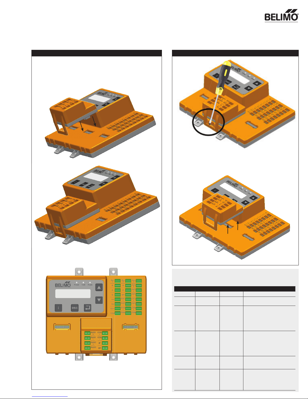
Each ZIP Economizer module is designed with a unique form fi t which allows it
to fi t only in one location on the ECON-ZIP-BASE.
Insert the ECON-ZIP-EM module in the center designated slot of the ZIP
Economizer base unit. Illustration located below for location.
Removal of ECON-ZIP-EM
Insert a fl at head screw driver into the latch of the module. Apply light
pressure on the latch away from the base unit. Lift up to remove.
Press fi rmly to lock the module in place – you will hear a snap.
02/13 - Subject to change. © Belimo Aircontrols (US A), Inc.
ECON-ZIP-EM
Technical Data
Type Name Description Electrical Specifi cation
Input CO2 +/-
Output IF
Output EF
Input AUX1 ±
Input AUX2 ±
CO2 sensor
input
Indoor fan
low speed
enable
Exhaust fan
enable
Auxiliary input
Purge contact
input
Auxiliary input
Remote
Potentiometer
Input
0-10 VDC
Sensor auto-detection
100'000 cycles @ inrush current
of 3A, normal current 1.5A
Impedance for Auto detection
@24 V:
<600 Ω @ 60Hz
<800 Ω @ 50Hz
100'000 cycles @ inrush current
of 3A, normal current 1.5A
Impedance for Auto detection
@ 24 V:
<600 Ω @ 60Hz
<800 Ω @ 50Hz
On/Off, 24 VAC, 50/60 Hz
Current load min. 10mA
2-10 VDC
1
Page 2
MOUNTING INSTRUCTION
ZIP Economizer™ Energy Module
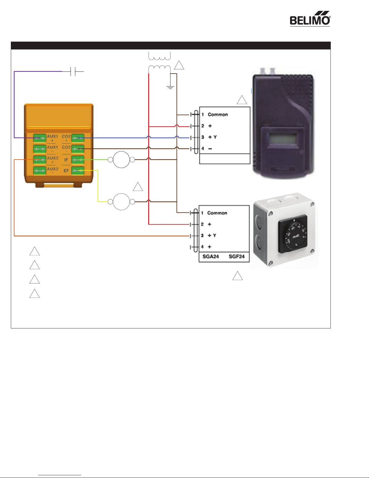
Wiring Diagrams
1
Purge Contact
Thermostat
24Vac
2
24Vac
Power
0-10Vdc
Signal
EFCLSF
Indoor Fan Low
Speed Relay /
VFD Enable
2
ECON-ZIP-EM
EFC
Power Exhaust
Fan Relay
1 Power Source should be same as ECON-ZIP-BASE
Not Supplied by Belimo
2
Sold Separately by Belimo
3
If the RTU has a 2 speed fan (IF wired), then W1 on
4
the ECON-ZIP-BASE needs to be wired as well, since
the fan shall not run in part load when heating.
CO2 Sensor
24Vac
Power
2-10Vdc
Signal
CO2 Sensor
Remote Potentiometer
3
2
02/13 - Subject to change. © Belimo Aircontrols (US A), Inc.
 Loading...