

Belimo B2100VB-024, B6400VB-350, B6600VB-507, B2150VB-055, B2200VB-077 Technical Documentation Manual
...Page 1

V BALL CONTROL VALVES
High Performance for
Aggressive Applications
• High performance ANSI Class 150
and 300 carbon steel bodies ideal for
aggressive applications.
• Fluid temperature up to 380°F is
ideal for chilled, hot water or steam service.
• Fitted with rotary actuators for easy fi eld
assembly and installation.
Victor A. Coppola, Vice President,
Product Management & Marketing
Page 2
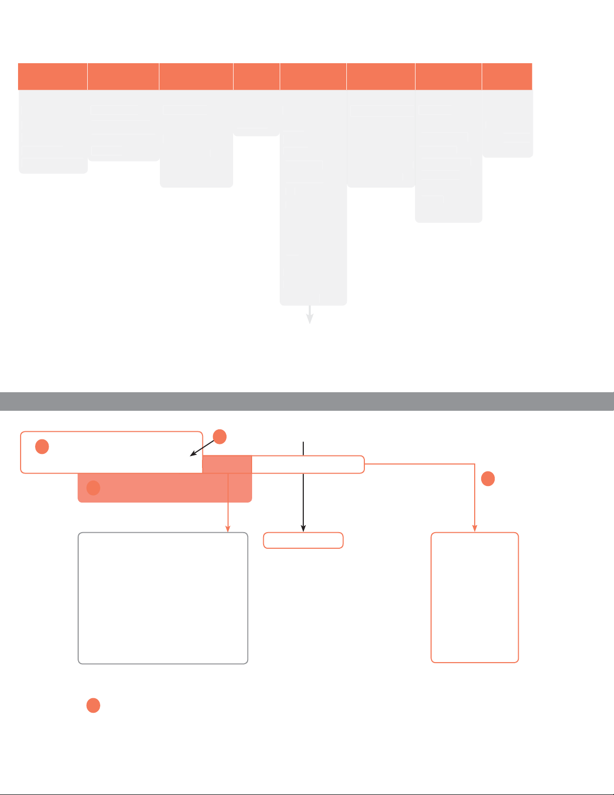
V Ball Val
ve Nomenclatur
e
.
S
.
S
1
n
O
g
gging?
g:
:
2
01
e
s
n
s
s
s
X
Create custo
T
g
e
X
C
T
e
O
n
d
S
s
n
d
n
d
e
)
e
”
)
l
ll
Typ
A
AFB, AFX
e
y
C
C
C
C
C
l
Technology
y
h
B2 100 VB -024 +AMX 24 -MFT-X1
Valv
B2 = 2-way
(1” to 2”)
B6 = 2-way
Valve Siz
12-50 = 1” to 2
80-150 = 3” to 6”
(Flanged
Flanged (3” to 6”
Ordering Example
ndustrial
Construction/
Materia
VB = Chrome
plated stainless
steel V ba
Cv
4 - 507
Actuator
Power Suppl
e
on-Spring
eturn
MB, AMX
MB, GMX
Y
Y…P
pring Return
FB, NFX
FX
lectronic
ail-Saf
KB, GKX
X” models are customizable.
4 = 24 VAC/D
20 = 120 VA
30 = 230 VA
P = 24-240 VA
r 24-125 VD
Contro
-3-X1 = On/Off,
loating Point
-MFT-X1 =
ulti-Function
-MFT95-1X =
-135
-S = Built-in
Auxiliar
witc
Choose the valve actuator combination
1
pecify preference or confi guration
2
Non-Spring Models
N
= Normally Ope
NC = Normally Close
pring Return Model
NO/FO = Normally Open/Fail Ope
NO/FC = Normally Open/Fail Close
NC/FO = Normally Closed/Fail Ope
NC/FC = Normally Closed/Fail Close
efers to valve ports A to AB.
Complete Ordering Example
5
Confi guratio
rogrammin
For MFT orders only - select programming cod
3
NO B2100VB-024+AMX24-MFT-X1 Tagging (if needed)
et-Up
P-10001 (A01)
P-100xx (Axx) Control voltage application
P-200xx (Wxx) Pulse width modulatio
application
P-300xx (Fxx) Floating Point application
P-400xx (Jxx) On/Off application
-XXXXX
confi
-XXXXX
confi guration in the fi eld
with MFT-actuator PC-Tool softwar
B2100VB-024+AMX24-MFT-X
: +N
: +A01
m MF
uration cod
reate custom MF
4
oes order
require
ta
Taggin
Valves may be tagged per
customer specifi cation.
($10.00 per tag)
xample
AHU-1
FCU-
art number for tagging:
1-001
Page 3
3
j
g
(
)
.
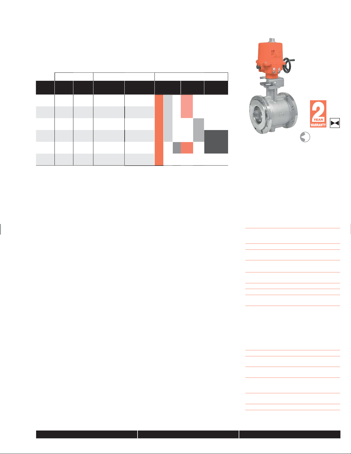
Control Valve Product Range
V
n
oduc
es
y
V
s
,
s
V
(60% gl
m
ge
”
)
)
s
®
n
®
g
S
.
)
)
i
i
e
p
e
V
V
e
52100VB-0
½
40
50
e
c
Ball Valve Product Range
alve Nominal Siz
C
Inches
v
DN
[mm]
2-way NPT
24 1 2
55 1
77 2
2150VB-055
2200VB-077
207
350 4 100
7
NOTE: Industrial ball valves have serviceable components. Proper maintenance of these parts will ensure a longer
n-service life for the valves. The seats of these valves will require replacement at an interval consistent with number
of full cycles the valve has be operated, or as fi eld condition dictates.
, Inc
USA
e. © Belimo Aircontrols
ect to chan
Tech.Doc - 04/17 - Sub
1
Type
24
2-way
Flanged
VB-207
6400VB-350
6600VB-507
Non-Spring
Return
AM Series
SY Series
uitable Actuators
Spring
Return
NF Series
AF
EF
GM
Electronic
Fail-Safe
GK Series
Equal Percentag
Characteristi
Mode of Operatio
The control valve is operated by an electronic actuator
that responds to a standard voltage for on/off control,
a modulating VDC/4…20 mA, or 3-point control
stem. The actuator will then move the ball of the
valve to the position dictated by the control signal thus
changing the fl ow.
r
t Featur
Equal percentage of fl ow
300:1 rangeabilit
ANSI Leakage Class I
Actuator Specifi cation
ontrol type on/off, fl oating point
modulating, 2-10 VDC
multi-function technology (MFT)
anual override all model
Electrical connection 3 ft. [1 m] cable with
½” conduit fi tting, terminal block
alve Specifi cations
ervice chilled or hot water,
Flow characteristic equal percenta
izes 1”, 1½”, 2”, 3”, 4”, 6
End fi tting SAE NPT female (1” to 2”
ANSI fl anged (3” to 6”
aterials
Body carbon steel
Characterizing ball hardened chrome plated
Stem stainless steel
Seats Tefl on
O-rings ALFAS
Stem packing spring loaded Tefl o
Bushings
edia temp. range 380°F max
ody pressure rating NPT ANSI 300 (1” to 2”
Flanged ANSI 150 (3” to 6”
aximum steam 100 ps
aximum water 100 ps
lose-off pressur
Water 150 psi
Steam 200
aximum inlet pressur
Steam 200 psi
Leakage ANSI Class I
ycol), stea
tainless steel
V-rin
tanyl PA46
si
800-543-9038 USA 866-805-7089 CANADA 203-791-8396 LATIN AMERICA
Page 4

4
Set-Up
V Ball Valves
.
.
T
s
1
,
T
.
v
.
†
†
.
(
)
.
SET-UP - Specify Upon Ordering
2-WAY VALVE
AMB24-3-X1, GMB24-3-X1,
SY..
AMX24-MFT-X1, GMX24-MFT-X1,
SY...MF
Stays in Last Position
NON-SPRING RETURN
AFB24-X1, AFBUP-X1,
NFB24-X
NFX24-MFT-X1, AFX24-MFT-X1
EFX24-MF
Note Fail Position
SPRING RETURN
Power to pin 2 will drive valve CW.
Power to pin 3 will drive valve CCW.
The above will fuction when the
directional switch is in the ”1” position
to reverse, select the ”0” position
NC: Normally closed A to AB, valve
will open as voltage increases
NO/FO: Normally open A to AB, valve
will drive closed.
Spring Action: Actuator will fail open A
to AB upon power loss.
NC/FO: Normally closed A to AB,
valve will open as voltage increases.
Actuator switch on CW.
Spring Action: Will fail open upon
power loss
Power to pin 4 will drive valve
W. Power to pin 3 will drive valve
W. The above will fuction when
the directional switch is in the ”Y2”
osition to reverse, select the ”Y1”
osition.
: Normally open A to AB, valve will
lose as voltage increase
C/FC: Normally closed A to AB, valve
will drive open.
Spring Action: Actuator will fail closed
A to AB upon power loss.
C/FC: Normally closed A to AB,
alve will open as voltage increases.
Actuator switch on CW.
Spring Action: Will fail closed upon
power loss
KX24-MFT-X1
ELECTRONIC FAIL-SAFE
† The GK series Electronic Fail-Safe actuator will drive to a predetermined postion using the FO/FC dial on the actuator upon loss of power
NC: Normally closed A to AB, will
open as voltage increases when
directional switch is in the ”Y2”
osition.
: Normally open A to AB, will close
as voltage increases when directional
witch is in the ”Y1” position.
, Inc
USA
Tech.Doc - 04/17 - Subject to change. © Belimo Aircontrols
800-543-9038 USA 866-805-7089 CANADA 203-791-8396 LATIN AMERICA / CARIBBEAN
Page 5
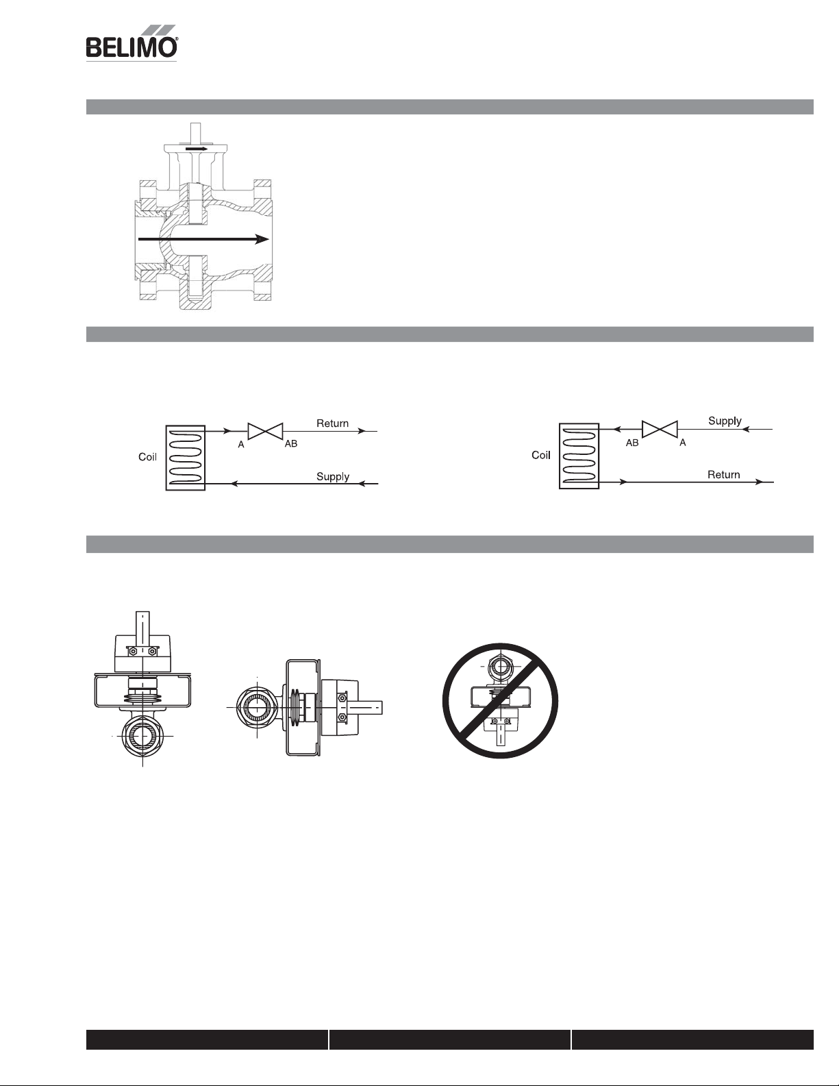
FLOW PATTERN
y
m
m
V Ball Valves
S
©
(
S
)
.
AAB
PIPING DIAGRAMS
General Information / Typical Installation
Water Application
2-way Valve Piping Diagra
team Application
2-way Valve Piping Diagra
PIPING/MOUNTING ORIENTATION
Assembly can be mounted horizontally or vertically for water applications. For steam applications the valve can be mounted vertically but if mounted horizontall
the valve must be 90° off center of the pipe. Do not install with actuator below pipe.
, Inc
A
U
Belimo Aircontrols
ubject to change.
Tech.Doc - 04/17 -
800-543-9038 USA 866-805-7089 CANADA 203-791-8396 LATIN AMERICA / CARIBBEAN
Page 6
f
s
.
o
.
o
a
.
a
v
c
t
.
f
.
.
v
.
g
.
S.
.
.
Th
l.
Mounting and Installation Instructions
Valves
(
)
.
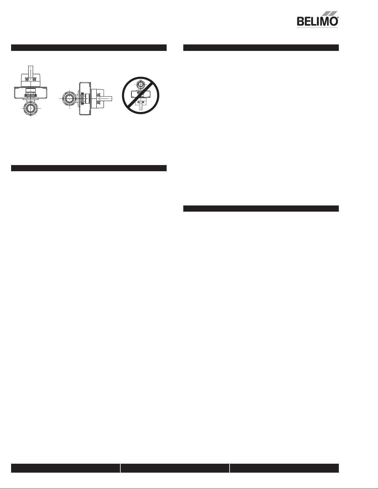
Mounting
e valves can be mounted in any position, except stem below horizonta
The fl ange allows the actuator to be either parallel or perpendicular to the pipe; there
are four orientations possible
If fi eld installing a spring return actuator, disconnect power and allow actuator to spring
closed. Flip actuator over if necessary to achieve proper rotation direction. DO NOT
USE THE REVERSING SWITCH TO DO THI
Two-way Valves Mounting
For NORMALLY CLOSED operation:
The ball of the valve must be rotated so that the ball is CLOSED to fl ow. The actuator
should be mounted with the clamp fully rotated CW (R). Spring return actuators will
show the CW (R) symbol near the clamp and position indicator. Depressing the gear
release to move the clamp rotates non-spring return actuators
For NORMALLY OPEN operation:
The ball of the valve must be rotated so that the ball is OPEN to fl ow. The actuator should
be mounted with the clamp fully rotated CCW (L). Spring return actuators will show the
W (L) symbol near the clamp and position indicator. Depressing the gear release to
move the clamp rotates non-spring return actuators. There are marks on the top of the
valve stem, which indicate the port directions
Installation
1.
nspect shipping package, valve, linkage, and actuator for physical damage. I
hipping damage has occurred notify appropriate carrier. Do not install
2.
nstall valve with the proper ports as inlets and outlets. Check that inlet and outlet
f 2-way valves are correct. Flow direction arrows must be correct.
.
low out all piping and thoroughly clean before valve installation
4.
lean male pipe threads with wire brush and rag. If threads have been damaged
r exposed to weather, running a tap or die over the threads may straighten them.
lean pipes, threads, and valve threads before installation; check for any foreign
aterial that can become lodged in trim components. Strainers should be cleaned
fter initial startup
.
ipe sealing compound should be applied sparingly after cleaning and may not be
pplied to the two lead threads of a screwed pipe, which are innermost inside the
alve. Sealing compound is to be placed on male threads only. The purpose is to
ubricate the pipes when tightening.
.Valve must be installed with the stem towards the vertical, not below horizontal.
7.Start the connection by turning the valve or pipe by hand as far as possible. Be
ertain the threads mate by the “feel” of the connection.
8.
se wrenches to tighten the valve to the pipe. Do not over tighten or strip the
hreads. Two wrenches are necessary to avoid damaging the valve.
. Two-way valve Normally Open or Closed confi gurations must be verifi ed by
xamining both the mechanical drawings and the valve and actuator.
Warning!
• Valve should not be used for combustible gas applications. Gas leaks and explosions
may result. Do not install in systems, which exceed the ratings of the valve
Avoid installations where valve may be exposed to excessive moisture, corrosive
umes, vibration, high ambient temperatures, elements, or high traffi c areas with
potential for mechanical damage
Valve assembly location must be within ambient ratings of actuator. If temperature is
elow -22°F a heater is required.
• The valve assembly will require heat shielding, thermal isolation, or cooling if
combined effect of medium and ambient temperatures – conduction, convection, and
adiation – is above 122°F for prolonged time periods at the actuator.
• Following standard procedure, a strainer should be installed before the coil and valve
or in another appropriate place in the system.
Visual access must be provided. Assembly must be accessible for routine schedule
service. Contractor should provide unions for removal from line and isolation valves
Avoid excessive stresses. Mechanical support must be provided where reducers have
been used and the piping system may have less structural integrity than full pipe sizes.
• Suffi cient upstream and downstream piping runs must be provided to ensure proper
alve capacity and fl ow response. Five diameters in each direction are recommended
• Life span of valve stems and O-rings is dependent on maintaining non-damagin
conditions. Poor water treatment or fi ltration, corrosion, scale, other particulate can
esult in damage to trim components. A water treatment specialist should be consulted.
ormal thread engagement between male pipe thread and valve body should be
observed. Pipe run that is in too far will damage the valve.
, Inc
USA
800-543-9038 USA 866-805-7089 CANADA 203-791-8396 LATIN AMERICA / CARIBBEAN
Tech.Doc - 04/17 - Subject to change. © Belimo Aircontrols
Page 7

Piping Reduction Chart
Valves
T
4
0
6
1
3
”
T
055
0.446.3
43.9
”
T
7
0
1
5
2
3
07
d
7
2
9
0
d
0
3
0
3
2
3
d
507
0491.5475.5
(
)
.
VALVE
SIZE
1” 24 2-Way NP
1½
2
” 2
4” 35
”
C
v
77 2-Way NP
TYPE MODEL #
2-Way NP
2-Way Flange
2-Way Flange
2-Way Flange
2100VB-02
2150VB2200VB-07
VB-02
6400VB-35
VB-
1”
Fp Cv
24.
1¼”
Fp Cv
22.
1½”
Fp Cv2”Fp Cv
21.
-
- -
--
.
19.
77.
LINE SIZE
2½”
Fp Cv3”Fp Cv4”Fp Cv5”Fp Cv6”Fp Cv8”Fp Cv
74.
70.
7.0191.3177.
--
- -
66.
50.0333.
13.
.
90.
7.
10”
Fp Cv
, Inc
USA
Tech.Doc - 04/17 - Subject to change. © Belimo Aircontrols
800-543-9038 USA 866-805-7089 CANADA 203-791-8396 LATIN AMERICA / CARIBBEAN
Page 8

f
/
.
)
.
C
1
C
s
Vol
or
F
KGM
AM
M
4
O
.
g
s
:
.
.
ips
s
.
Wiring Instructions
Valves
(
)
.
GENERAL WIRING INSTRUCTIONS
WARNING The wiring technician must be trained and experienced with
electronic circuits. Disconnect power supply before attempting any wiring
connections or changes. Make all connections in accordance with wiring
diagrams and follow all applicable local and national codes. Provide
disconnect and overload protection as required. Use copper, twisted pair
conductors only. If using electrical conduit, the attachment to the actuator
must be made with fl exible conduit.
Always read the controller manu
efore making any connections. Follow all instructions in this literature. If you
have any questions, contact the controller manufacturer and
Trans forme r(s
Typically actuators require a 24 VAC Class 2 transformer and draws a maximum of 10
VA per actuator. The actuator enclosure cannot be opened in the fi eld; there are no
parts or components to be replaced or repaired
– EMC directive: 89 /336/EE
– Software Class A: Mode of operation Type
– Low voltage directive: 73/23/ EE
Typical Transformer Sizing
Actuator Serie
A
G
N
acturer’s installation literature carefully
or Belimo
tage
24
ax. VA Per Actuat
CAUTION It is good practice to power electronic or digital controllers from a
separate power transformer. The power supply design in our actuators and
other end devices use half wave rectifi cation. Some controllers use full wave
rectifi cation. When these two different types of power supplies are connected
to the same power transformer and the DC commons are connected together, a
short circuit is created across one of the diodes in the full wave power supply,
damaging the controller. Only use a single power transformer to power the
controller and actuator if you know the controller power supply uses half wave
rectifi cation.
ultiple Actuators, One Transformer
Multiple actuators may be powered from one transformer provided the following rules
are followed:
1. The T
2. Polarity on the secondary transformer is strictly followed. This means that all
Multiple actuators positioned by the same control signal may be powered from
multiple transformers provided the following rules are followed
Wire Type and Wire Installation T
For most installations, 18 or 16 Ga. cable works well with Belimo actuators. Use
code-approved wire nuts, terminal strips or solderless connectors where wires
are joined. It is good practice to run control wires unspliced from the actuator to
the controller. If splices are unavoidable, make sure the splice can be reached for
TAL current draw of the actuators (VA rating) is less than or equal to the
rating of the transformer
No. 1 wires from all actuators are connected to the common le
transformer and all No. 2 wires from all actuators are connected to the hotleg.
Mixing wire No. 1 & 2 on one leg of the transformer will result in erratic operation
or failure of the actuator and /or controls.
ultiple Actuators, Multiple Transformer
. Transformers are properly sized
. All No. 1 wires from all actuators are tied together and tied to the negative leg of
the control signal. See wiring diagram
ossible maintenance. Tape and/or wire-tie the splice to reduce the possibility of the
plice being inadvertently pulled apart
on the
, Inc
USA
Tech.Doc - 04/17 - Subject to change. © Belimo Aircontrols
8
800-543-9038 USA 866-805-7089 CANADA 203-791-8396 LATIN AMERICA / CARIBBEAN
Page 9
S
©
(
S
)
.
g
n
.
.
.
.
4
s
s
”
s
.
.
.
.
2
2
i
g
4
g
Installation Recommendations
Valves
* Beli
.
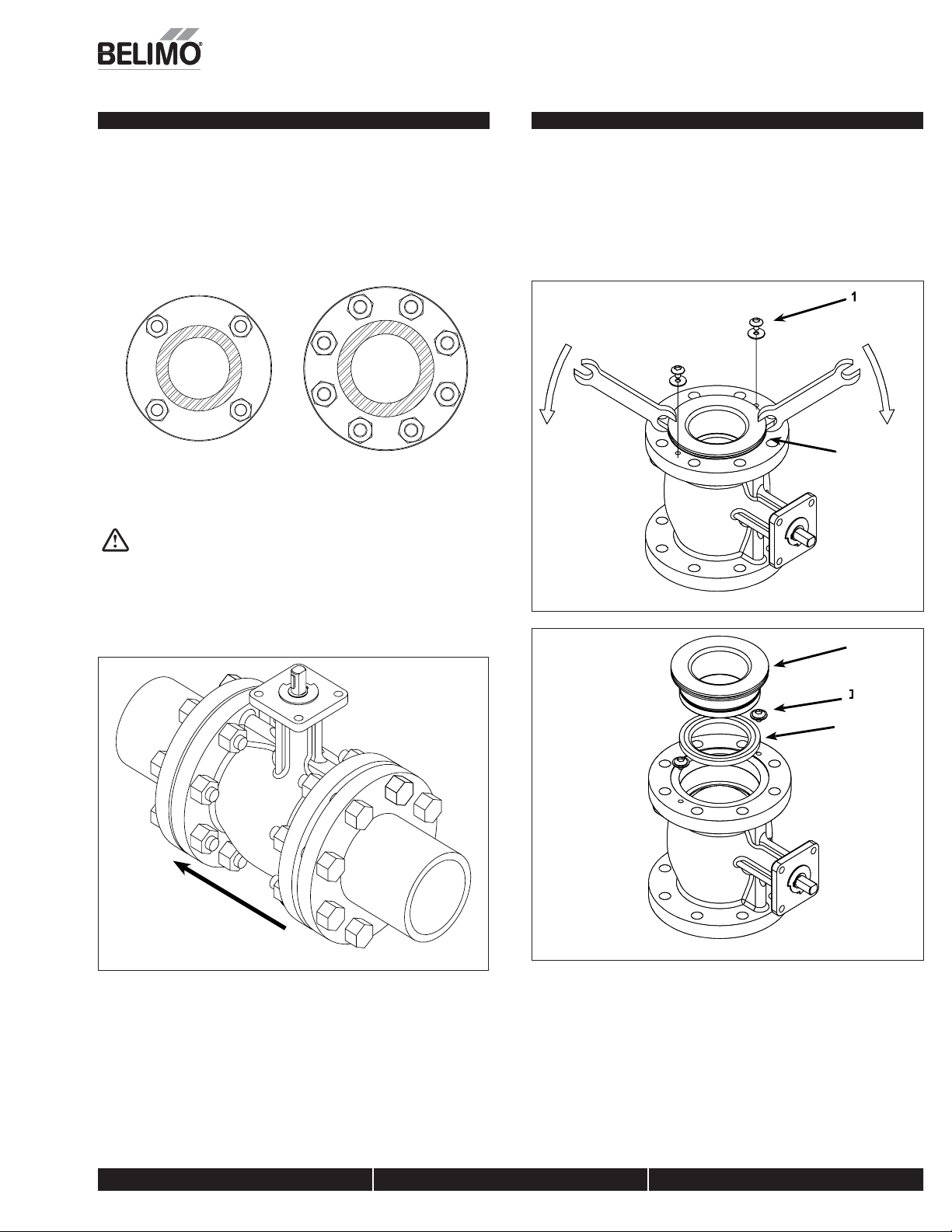
Valve Installation Procedure
3”, 4” & 6” Valves - Flan
1. Valve must be in the closed position for installation
2. Figure 1 illustrates a fl anged valve installation
. Use hex bolts & nuts to secure valve to fl ange.
4. Ensure proper gaskets are used between the valve fl ange and pipe fl ange
.Tighten bolts & nuts in alternating opposite sides until completely tightened.
Please see torque requirements below. Torque wrench is required
1
ed Installatio
3
1
8
5
3
4
3” Bolt T
Sequence
ghtenin
2
7
” & 6” Bolt Tightenin
Sequence
2
ARNING: Exceeding the Maximum Torque Can Damage the Valve and
oid the Warranty!
3” ANSI 150 Flange - 65 ft/lbs
” ANSI 150 Flange - 70 ft/lb
6” ANSI 150 Flange - 100 ft/lb
Seat Replacement Procedure*
, 4” & 6” Valve
3
1. Remove valve from pipe
2. Remove 2 cap retaining washers (1).
. Using 2 wrenches or fl at-head screwdrivers, pr y cap assembly
4. Rotate valve to fully open position
.
sing hands, pull seat
6. Replace seat and reverse procedure to reassemble.
. Reinstall valve per installation instructions
3) out of the valve
2) out of valve.
4
6
igure 2
, Inc
A
U
Belimo Aircontrols
ubject to change.
Figure 1
Tech.Doc - 04/17 -
igure 3
mo does not sell seat replacement kits
800-543-9038 USA 866-805-7089 CANADA 203-791-8396 LATIN AMERICA / CARIBBEAN
9
Page 10
0
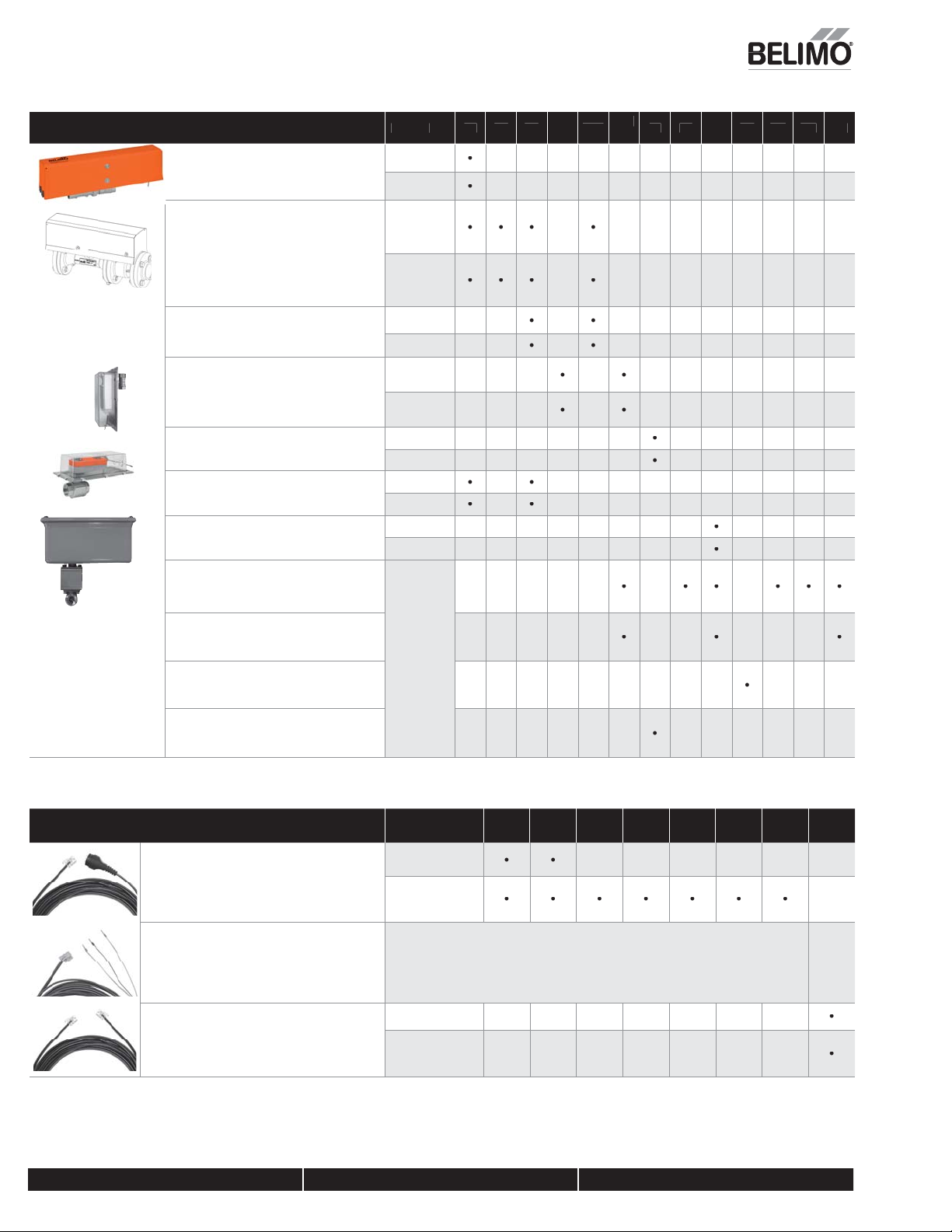
Valve Accessories
F
)
s
V
F
-
)
)
s
V
0
)
s
V
0
)
s
V
*
s
VCCVZS-CC
*
s
VCCV
*
s
VCCVZS-S
0
s
s
0
2
3
Weather Shields
V
S
A
N
/
t
s
s
/
t
s
t
es
s
(
)
.
ZS-EPIV-EV-20-N
For valve sizes ½” [DN15] to ¾” [DN20] (cover
only
ALVE
nergy Valve
ePI
R
K/
KR
F/
M
ZS-EPIV-EV-50-SCN
For valve sizes 1” [DN25] to 2” [DN50] on non
fail-safe actuator series (cover only
For valve sizes ½” [DN15] to 2” [DN50] on
electronic fail-safe actuator series (cover only
ZS-EPIV-EV-8
For ANSI 125, valve sizes 2½” [DN65] and 3”
[DN80] (cover only
ZS-EPIV-EV-15
For ANSI 125, valve sizes 4” [DN100], 5”
[DN125], and 6” [DN150] (cover only
ZS-CCV-90
it for LF actuator serie
V-100
it for LR/AR actuator serie
ZS-CCV-110
it for AFR actuator serie
PBV-1
For NM, AM,GM, NF, AF, and GK
actuator serie
ZS-SPBV-2
For dual mounted GM, AF, and GK actuator series
ZS-BVVS-000
For LM actuator series on VS/VSS models
ZS-BVVS-000
For LF actuator series on VS/VSS models
Energy Valve
ePI
Energy Valve
ePI
Energy Valve
ePI
PICC
PICC
PICC
all Valve
, Inc
USA
ZTH REPLACEMENT CABLES VALVES AM GM AR GR DR GK DK SY
ZK1-GE
able for use with ZTH US to connect to new
eneration non-spring return actuator via diagnostic
programming socke
ZK2-GEN
able for use with ZTH US to connect to new
eneration non-spring return actuator via diagnostic
programming socke
ZK6-GEN
able for use with ZTH US to connect to SY actuator
via RJII por
all Valve
utterfl y Valve
Available for all MFT Actuator
ll Valv
utterfl y Valve
800-543-9038 USA 866-805-7089 CANADA 203-791-8396 LATIN AMERICA / CARIBBEAN
1
Tech.Doc - 04/17 - Subject to change. © Belimo Aircontrols
Page 11
Valve Accessories
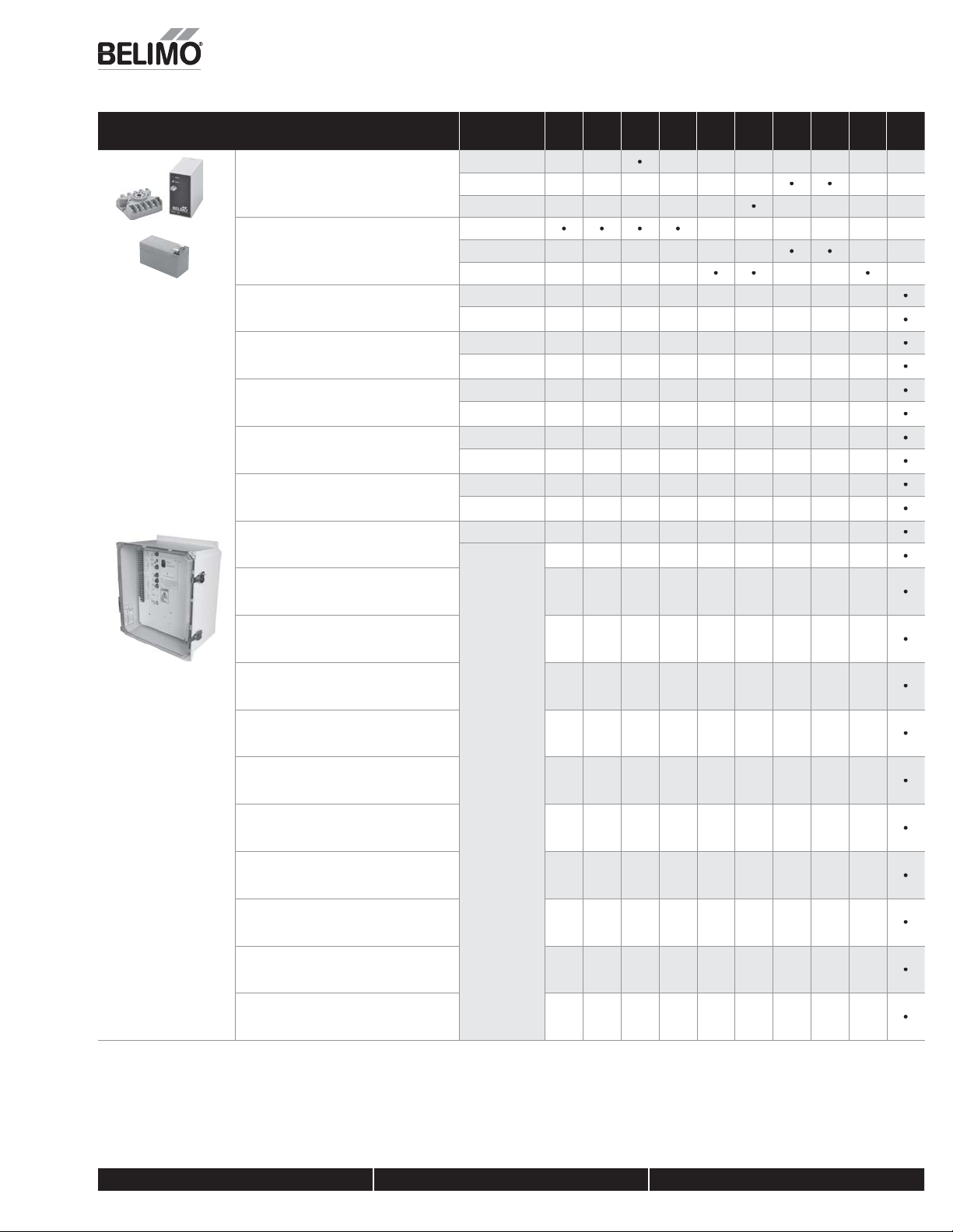
BATTERY BACKUP VALVES
S
e
s
s
s
)
s
s
s
*
s
s
s
*
s
s
s
*
s
s
s
*
s
s
s
*
s
es
s
*
s
s
s
*
s
*
s
*
s
*
s
*
s
*
s
*
s
*
s
*
s
*
s
(
)
.
all Valve
NSV24 U
Battery backup modul
NSV-BAT
2VDC 1.2 AH battery
2 required
EXT-NSV-B01-120
Battery backup system for SY1 - SY3 120 VAC,
n/off actuator
EXT-NSV-B02-120
Battery backup system for SY1 - SY3 120 VAC,
MFT actuator
EXT-NSV-B11-24
Battery backup system for SY1
24 VAC, on/off actuator
EXT-NSV-B12-24
Battery backup system for SY1
24 VAC, MFT actuator
EXT-NSV-B21-230
Battery backup system for SY1 - SY3 230 VAC,
n/off actuator
EXT-NSV-B22-230
Battery backup system for SY1 - SY3 230 VAC,
MFT actuator
EXT-NSV-B03-120
Battery backup system for SY4 - SY6 120 VAC,
n/off actuator
EXT-NSV-B04-120
Battery backup system for SY4 - SY6 120 VAC,
MFT actuator
EXT-NSV-B05-120
Battery backup system for SY7 - SY12 120 VAC,
, Inc
USA
Tech.Doc - 04/17 - Subject to change. © Belimo Aircontrols
n/off actuator
EXT-NSV-B06-120
Battery backup system for SY7 - SY12 120 VAC,
actuator
EXT-NSV-B13-24
Battery backup system for SY2 - SY5 24 VAC,
n/off actuator
EXT-NSV-B14-24
Battery backup system for SY2 - SY5 24 VAC,
MFT actuator
EXT-NSV-B23-230
Battery backup system for SY4 - SY6 230 VAC,
n/off actuator
EXT-NSV-B24-230
Battery backup system for SY4 - SY6 230 VAC,
MFT actuator
EXT-NSV-B25-230
Battery backup system for SY7 - SY12 230 VAC,
n/off actuator
EXT-NSV-B26-230
Battery backup system for SY7 - SY12 230 VAC,
MFT actuator
Globe Valve
utterfl y Valve
all Valve
Globe Valve
utterfl y Valve
all Valve
utterfl y Valve
all Valve
utterfl y Valve
all Valve
utterfl y Valve
all Valve
utterfl y Valve
ll Valv
utterfl y Valve
all Valve
utterfl y Valve
LM/LRNM/
NR
• •
AM GM AR
•
GR/
EV RV PR SY
DR
•
•
800-543-9038 USA 866-805-7089 CANADA 203-791-8396 LATIN AMERICA / CARIBBEAN
11
Page 12
2
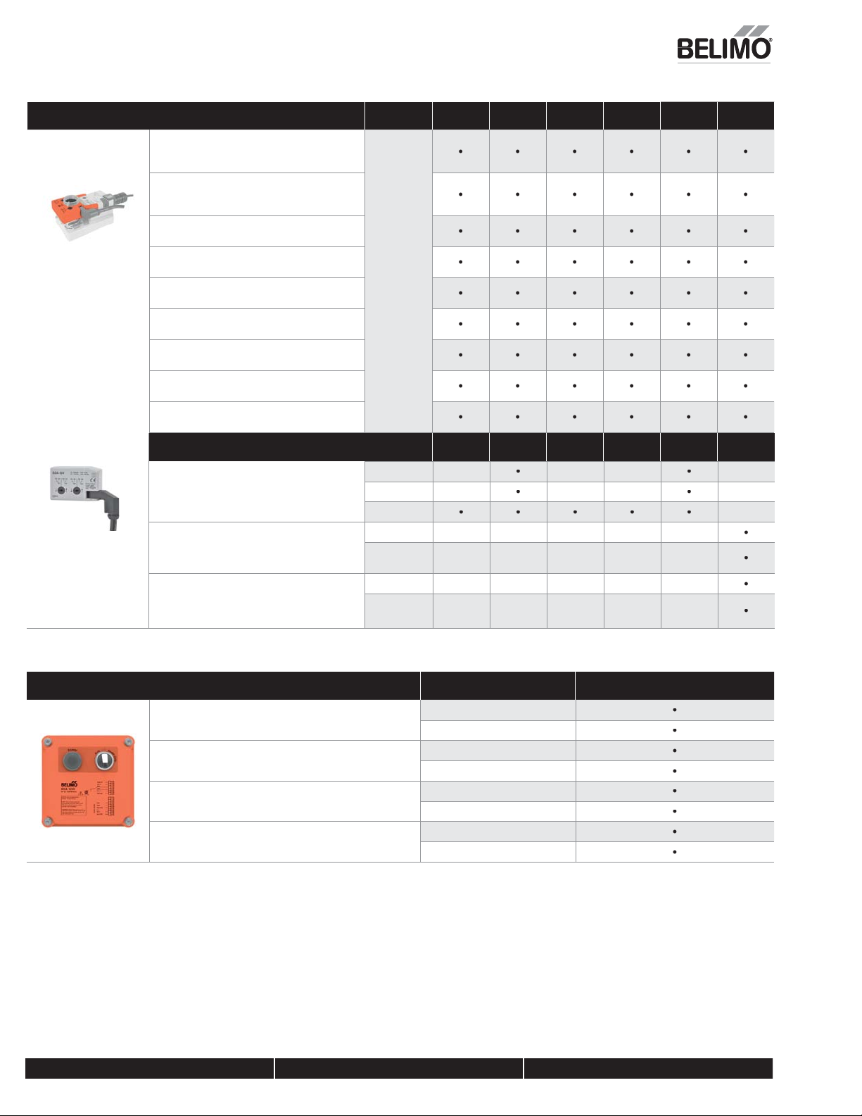
AUXILIARY SWITCHES & POTENTIOMETERS VALVES LR/LM NR/NM AR/AM GR/GM AK GK/GKR
A
C
A
A
s
A
C
GR
GR
00
GR
GR
2800
R
10000
V
s.
s
PIV
s
ly
s
Valves
y
s
V
s
V
n
s
s
T
g
s
s
V
n
s
s
T
g
s
s
Valve Accessories
(
)
.
1
Auxiliary switch 1x SPDT, 3A
0.5A inductive) @ 250 VA
2
Auxiliary switch 2x SPDT, 3A
(0.5A inductive) @ 250 VA
P140A
Feedback potentiometer 140
P500A
eedback potentiometer 5
P500A
Feedback potentiometer 500
P1000A GR
Feedback potentiometer 1000
P2800A
eedback potentiometer
P5000A GR
Feedback potentiometer 5000
P10000A G
eedback potentiometer
vailable for
ll Valve
LVK/SVK
2A-G
Auxiliary switch 2x SPDT, 3A
0.5A inductive) @ 250 VAC for LV, SV, EV, and AVK
ries actuator
Y-1000-FB01
Feedback potentiometer 1000, 2 position, factory
nstalled option on
Y-1000-FB02
Feedback potentiometer 1000, modulating
(models Syx…-P, -SR or MFT), factory installed
ption onl
VALVES LV/SV EV RV
Energy Valve
e
Globe Valve
all Valve
utterfl y
all Valve
utterfl y
alve
ELECTRIC DISCONNECT VALVES SY
HOA-120
Local electric disconnect for SY2-SY12 110/230V - 2 positio
HOA-120VMF
Local electric disconnect for SY2-SY12 110/230V - modulatin
HOA-24
Local electric disconnect for SY2-SY12 24V - 2 positio
HOA-24VMF
Local electric disconnect for SY2-SY12 24V - modulatin
all Valve
utterfl y Valve
all Valve
utterfl y Valve
all Valve
utterfl y Valve
all Valve
utterfl y Valve
AVK SY
, Inc
USA
800-543-9038 USA 866-805-7089 CANADA 203-791-8396 LATIN AMERICA / CARIBBEAN
1
Tech.Doc - 04/17 - Subject to change. © Belimo Aircontrols
Page 13
3
PROGRAMMING TOOLS
p
A
a
y
y
w
l
s
S
a
a
s
s
T
T
s
)
Val
S
©
(
S
)
.
COVERS
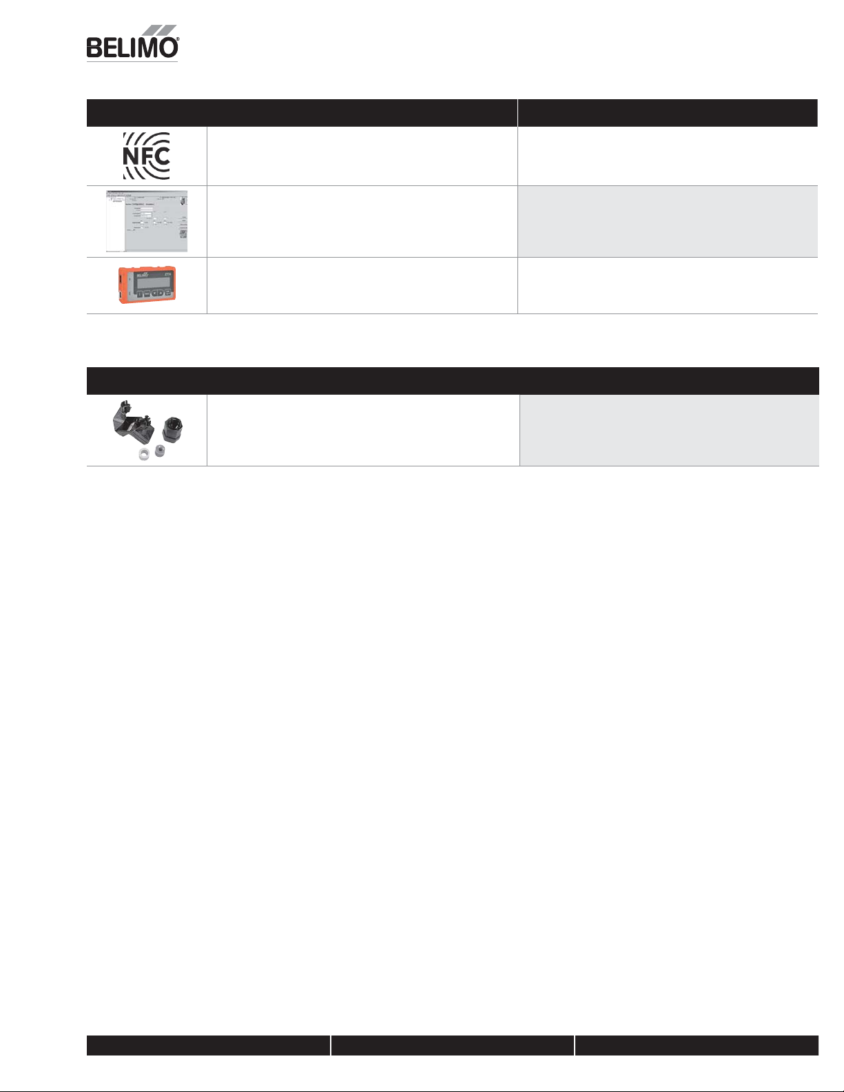
ear Field Communication (NFC) Ap
llows fast programming, commissioning, and troubleshooting even when the
ctuator is not powered. Available through Google Pla
FT-P
elimo MFT confi guration software (V3.X), includes PC-Tool software
interface cables [ZTH US] not included).
Physical copy of software. Free download also available at
ww.belimo.us/americas/mft.htm
ZTH U
andheld interface module that
llows fi eld programming. Includes ZK1-GEN, ZK2-GEN,
nd ZK6-GEN cable
ve Accessories
here Available on NFC Labeled Actuators Onl
Available for all MFT Actuator
Available for all MFT Actuator
ZS-
erminal cover for NEMA 2, -T models
, Inc
A
U
Belimo Aircontrols
ubject to change.
Available for all -T Model Actuator
except TR
Tech.Doc - 04/17 -
800-543-9038 USA 866-805-7089 CANADA 203-791-8396 LATIN AMERICA / CARIBBEAN
1
 Loading...