

Page 1

Globe valve actuator with emergency
!
control function for 2-way and 3-way
globe valves
• Actuating force 2000 N
• Nominal voltage AC 230 V
• Control 3-point
• Nominal stroke 32 mm
• Design life SuperCaps: 15 years
Technical data
Electrical data Nominal voltage AC 230 V
Functional data
Safety
Weight
Terms
Technical data sheet AVK230A-3
Nominal voltage frequency 50/60 Hz
Nominal voltage range AC 85...265 V
Power consumption in operation 3.5 W
Power consumption in rest position 1.5 W
Power consumption for wire sizing 6.5 VA
Connection supply / control Cable 1 m, 4 x 0.75 mm²
Parallel operation Yes (note the performance data)
Actuating force motor 2000 N
Setting emergency setting position (POP) Actuator spindle retracted / extended,
adjustable (POP rotary button)
Manual override with push-button
Nominal stroke 32 mm
Actuating time motor 150 s / 32 mm
Actuating time emergency control
function
Sound power level motor 60 dB(A)
Sound power level emergency control
position
Position indication Mechanically, 5...32 mm stroke
Protection class IEC/EN II reinforced insulation
Protection class UL UL Class 2 Supply
Degree of protection IEC/EN IP54
Degree of protection NEMA/UL NEMA 2, UL Enclosure Type 2
EMC CE according to 2014/30/EU
Low voltage directive CE according to 2014/35/EU
Certification IEC/EN IEC/EN 60730-1 and IEC/EN 60730-2-14
Certification UL cULus according to UL 60730-1A, UL 60730-2-
Mode of operation Type 1.AA
Rated impulse voltage supply / control 4 kV
Control pollution degree 3
Ambient temperature 0...50°C
Non-operating temperature -40...80°C
Ambient humidity 95% r.h., non-condensing
Maintenance Maintenance-free
Weight 4.4 kg
Abbreviations POP = Power off position / emergency setting
35 s / 32 mm
60 dB(A)
14 and CAN/CSA E60730-1:02
position
CPO = Controlled power off / controlled
emergency control function
PF = Power fail delay time / bridging time
Safety notes
• This device has been designed for use in stationary heating, ventilation and air
conditioning systems and must not be used outside the specified field of application,
especially in aircraft or in any other airborne means of transport.
www.belimo.eu
AVK230A-3 • en-gb • 2017-03-09 • subject to changes
1
Page 2
20
25
30
]
AVK230A-3
Safety notes
Product features
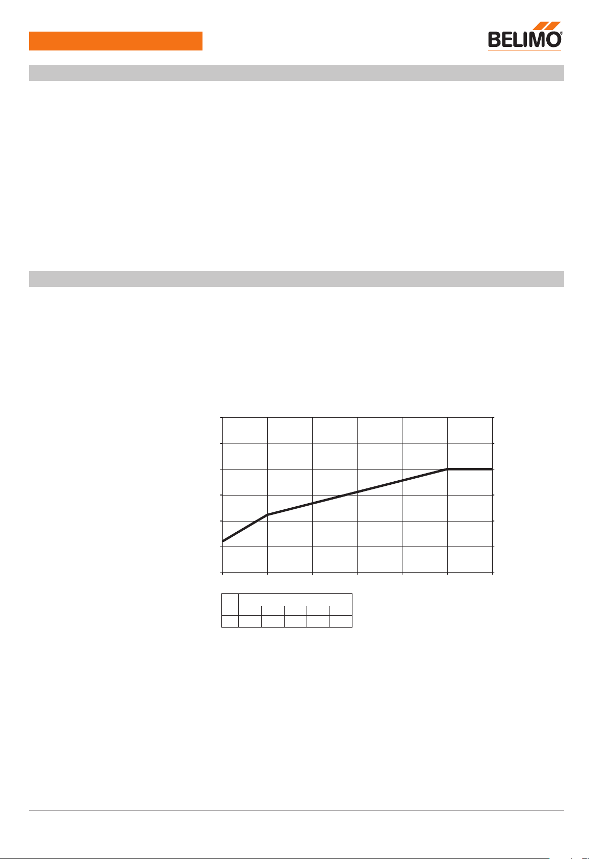
Pre-charging time (start up)
Mode of operation
SuperCap globe valve actuator, 3-point, AC 230 V, 2000 N
• Outdoor application: only possible in case that no (sea)water, snow, ice, insolation
or aggressive gases interfere directly with the actuator and that is ensured that the
ambient conditions remain at any time within the thresholds according to the data
sheet.
• Only authorised specialists may carry out installation. All applicable legal or
institutional installation regulations must be complied during installation.
• The switch for changing the direction of motion and so the closing point may be
adjusted only by authorised specialists. The direction of motion is critical, particularly
in connection with frost protection circuits.
• The device may only be opened at the manufacturer’s site. It does not contain any
parts that can be replaced or repaired by the user.
• Cables must not be removed from the device.
• The device contains electrical and electronic components and must not be disposed
of as household refuse. All locally valid regulations and requirements must be
observed.
The actuator moves the valve to the desired operating position at the same time as
the integrated capacitors are loaded. Interrupting the supply voltage causes the valve
to be moved to the selected emergency setting position (POP) by means of stored
electrical energy.
The capacitor actuators require a pre-charging time. This time is used for charging the
capacitors up to a usable voltage level. This ensures that, in the event of an electricity
interruption, the actuator can move at any time from its current position into the preset
emergency setting position (POP). The duration of the pre-charging time depends
mainly on how long the power was interrupted.
Typical pre-charging time
30
[s] [s
25
[d] = Electricity interruption in days
[s] = Pre-charging time in seconds
Delivery condition (capacitors)
Simple direct mounting
Manual override
High functional reliability
20
15
10
5
0
0
246810 12
[d]
15
10
5
0
[d]
0 127≥10
[s]
6911 16 20
The actuator is completely discharged after delivery from the factory, which is why the
actuator requires approximately 20 s pre-charging time before initial commissioning in
order to bring the capacitors up to the required voltage level.
Simple direct mounting on the globe valve by means of form-fit hollow clamping jaws.
The actuator can be rotated by 360° on the valve neck.
Manual control with push-button possible - temporary. The gear is disengaged and the
actuator decoupled for as long as the button is pressed.
The stroke can be adjusted by using a hexagon socket screw key (5 mm), which
is inserted into the top of the actuator. The stroke spindle extends when the key is
rotated clockwise.
The actuator is overload protected, requires no limit switches and automatically stops
when the end stop is reached.
2
AVK230A-3 • en-gb • 2017-03-09 • subject to changes
www.belimo.eu
Page 3
AVK230A-3
Product features
Combination valve/actuator
Position indication
Home position
Direction of stroke switch
Emergency setting position (POP)
Accessories
Electrical accessories
rotary knob
SuperCap globe valve actuator, 3-point, AC 230 V, 2000 N
Refer to the valve documentation for suitable valves, their permitted medium
temperatures and closing pressures.
The stroke is indicated mechanically on the bracket with tabs. The stroke range
adjusts itself automatically during operation.
Factory setting: Actuator spindle is retracted.
When valve-actuator combinations are shipped, the direction of motion is set in
accordance with the closing point of the valve.
When actuated, the direction of stroke switch changes the running direction in normal
operation. The direction of stroke switch has no influence on the emergency setting
position (POP) which has been set.
The rotary knob «Emergency setting position» can be used to adjust the desired
emergency setting position (POP). The POP range allways refers to the maximum
height of stroke of the actuator.
In the event of an electricity interruption, the actuator will move into the selected
emergency setting position (POP), taking into account the bridging time (PF) of 2 s
which was set ex-works.
Description Type
Auxiliary switch, 2 x SPDT, add-on, grey S2A-H
Electrical installation
!
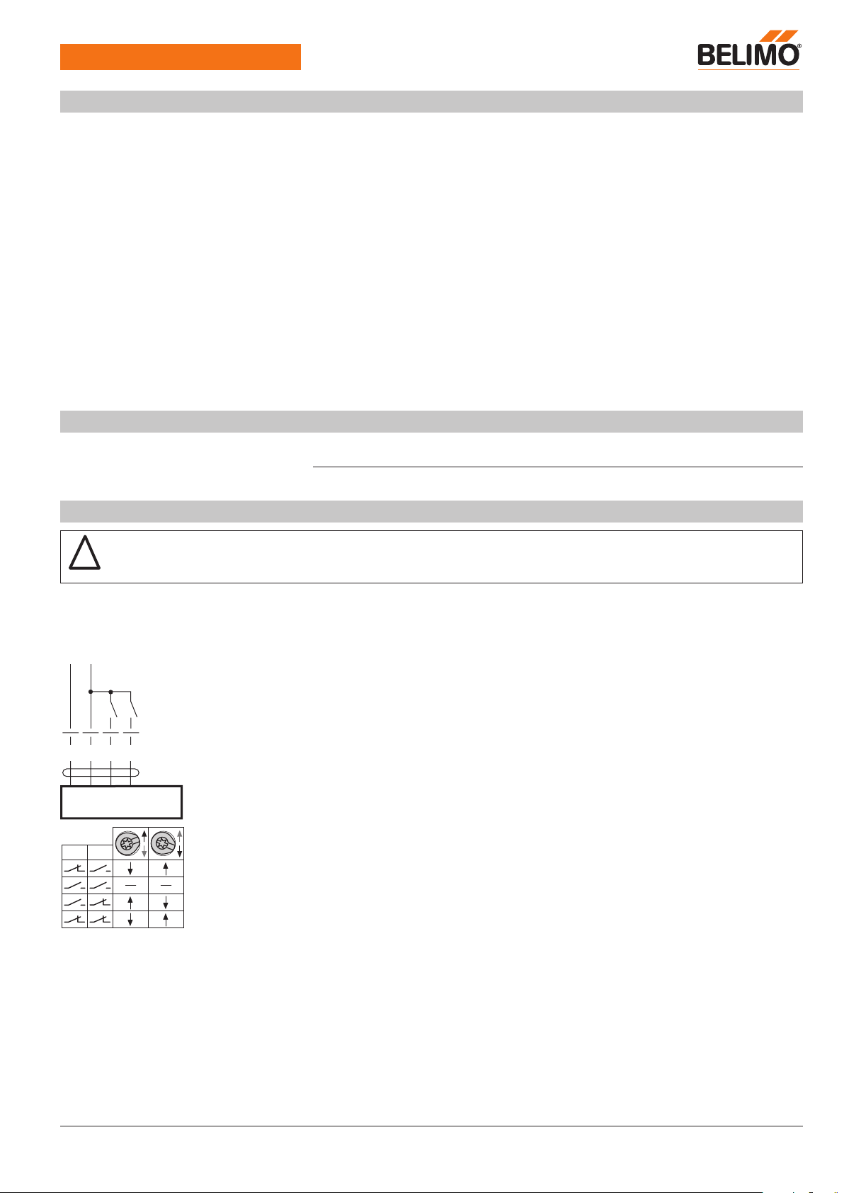
Wiring diagrams
AC 230 V, 3-point
NL
b
a
1 32 4
b
a
Notes • Caution: Power supply voltage!
• Parallel connection of other actuators possible. Observe the performance data.
• Direction of stroke switch factory setting: Actuator spindle retracted.
Cable colours:
1 = black
2 = red
3 = white
4 = white
www.belimo.eu
AVK230A-3 • en-gb • 2017-03-09 • subject to changes
3
Page 4
AVK230A-3
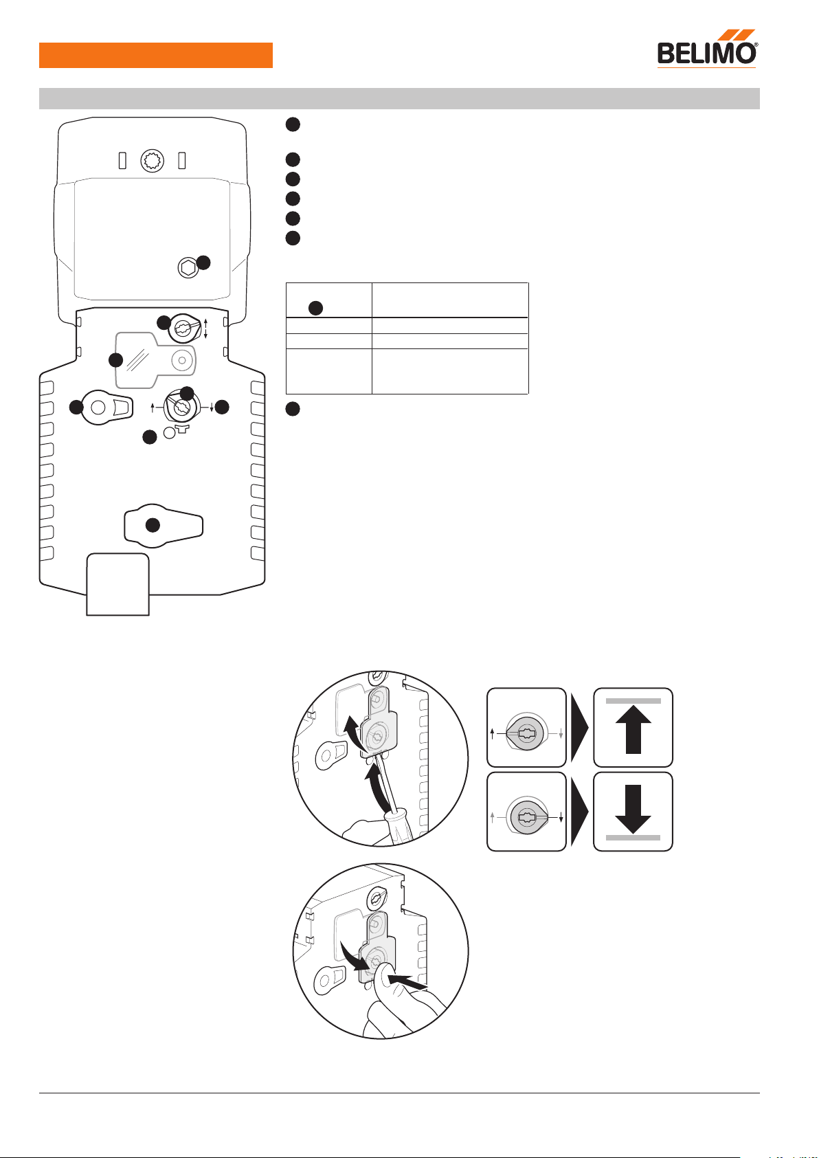
Operating controls and indicators
10
SuperCap globe valve actuator, 3-point, AC 230 V, 2000 N
1
Direction of stroke switch
Switch over: Direction of stroke changes
2
Cover, POP button
3
POP button
4
Scale for manual adjustment
6
(No function)
7
Gear disengagement button
Press button:
Release button:
Gear disengaged, motor stops, manual operation possible
Gear engaged, standard mode
LED display
8
green
1
On Operation OK
Meaning / function
Flashing POP function active
2
Off – Not in operation
– Pre-charging time SuperCap
POP
3
7
4
10
Manual override
Clockwise:
8
Status
6
Counterclockwise:
– Fault SuperCap
Actuator spindle extends
Actuator spindle retracts
Setting emergency setting position (POP)
4
AVK230A-3 • en-gb • 2017-03-09 • subject to changes
www.belimo.eu
Page 5
AVK230A-3
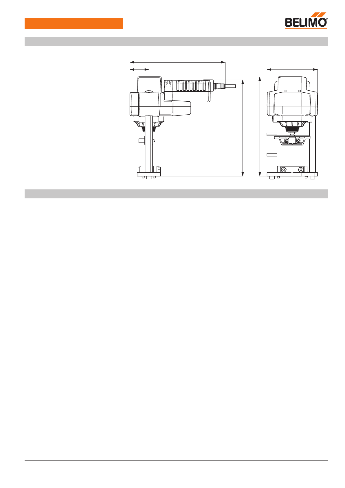
Dimensions [mm]
SuperCap globe valve actuator, 3-point, AC 230 V, 2000 N
Dimensional drawings
262
276
264
14053
Further documentation
• Overview Valve-actuator combinations
• Data sheets for globe valves
• Installation instructions for actuators and/or globe valves
• Notes for project planning 2-way and 3-way globe valves
• General notes for project planning
www.belimo.eu
AVK230A-3 • en-gb • 2017-03-09 • subject to changes
5
 Loading...