

Page 1
71074-00004
Technical Data AFRB24-SR, AFRB24-SR-S,
AFRX24-SR, AFRX24-SR-S
Power supply 24 VAC ±20%, 50/60 Hz
Power consumption running
Transformer sizing 8.5 VA (class 2 power source)
Electrical connection
AFRB... 3 ft, 18 GA appliance cable, 1/2" conduit
AFRX...
Overload protection electronic throughout 0 to 90° rotation
Operating range Y 2 to 10 VDC, 4 to 20mA
Input impedance 100 kΩ for 2 to 10 VDC (0.1 mA)
Feedback output U 2 to 10 VDC (max. 0.5 mA)
Direction of rotation spring reversible with CW/CCW mounting
Mechanical angle of rotation 90° (adjustable with mechanical end stop, 35° to
Running time
Position indication visual indicator, 0° to 90°
Manual override 5 mm hex crank (³⁄₁₆" Allen), supplied
Humidity max. 95% RH non-condensing
Ambient temperature -22°F to 122°F [-30°C to 50°C]
Storage temperature -40°F to 176°F [-40°C to 80°C]
Housing Nema 2, IP54, Enclosure Type2
Housing material zinc coated metal and plastic casing
Agency listings
Noise level ≤40dB(A) motor @ 90 seconds
Quality standard ISO 9001
† Rated Impulse Voltage 800V, Type of action 1.AA (1.AA.B for -S version), Control Pollution Degree 3.
AFRB24-SR-S, AFRX24-SR-S
Auxiliary switches 2 x SPDT 3A (0.5A) @ 250 VAC, UL approved
† cULus acc. to UL60730-1A/-2-14, CAN/CSA
24 VDC +20% / -10%
5.5 W
holding
3 W
connector
-S models: two 3 ft, 18 gauge appliance cables
with 1/2” conduit connectors
3 ft [1m], 10 ft [3m] or 16 ft [5m] 18 GA
appliance or plenum cables, with or without 1/2”
conduit connector
-S models: Two 3 ft [1m], 10 ft [3m] or
16 ft [5m] appliance cables, with or without 1/2"
conduit connectors
500 Ω for 4 to 20 mA
motor reversible with built-in switch
90°)
spring
< 20 seconds @ -4°F to 122°F [-20°C to 50°C];
< 60 seconds @ -22°F [-30°C]
motor
90 seconds
(0° is full spring return position)
E60730-1:02, CE acc. to 2004/108/EC &
2006/95/EC
≤62dB(A) spring return
one set at +10°, one adjustable 10° to 90°
AFRB24-SR, AFRB24-SR-S, AFRX24-SR, AFRX24-SR-S
Proportional, Spring Return, 24 V, for 2 to 10 VDC or 4 to 20 mA Control Signal
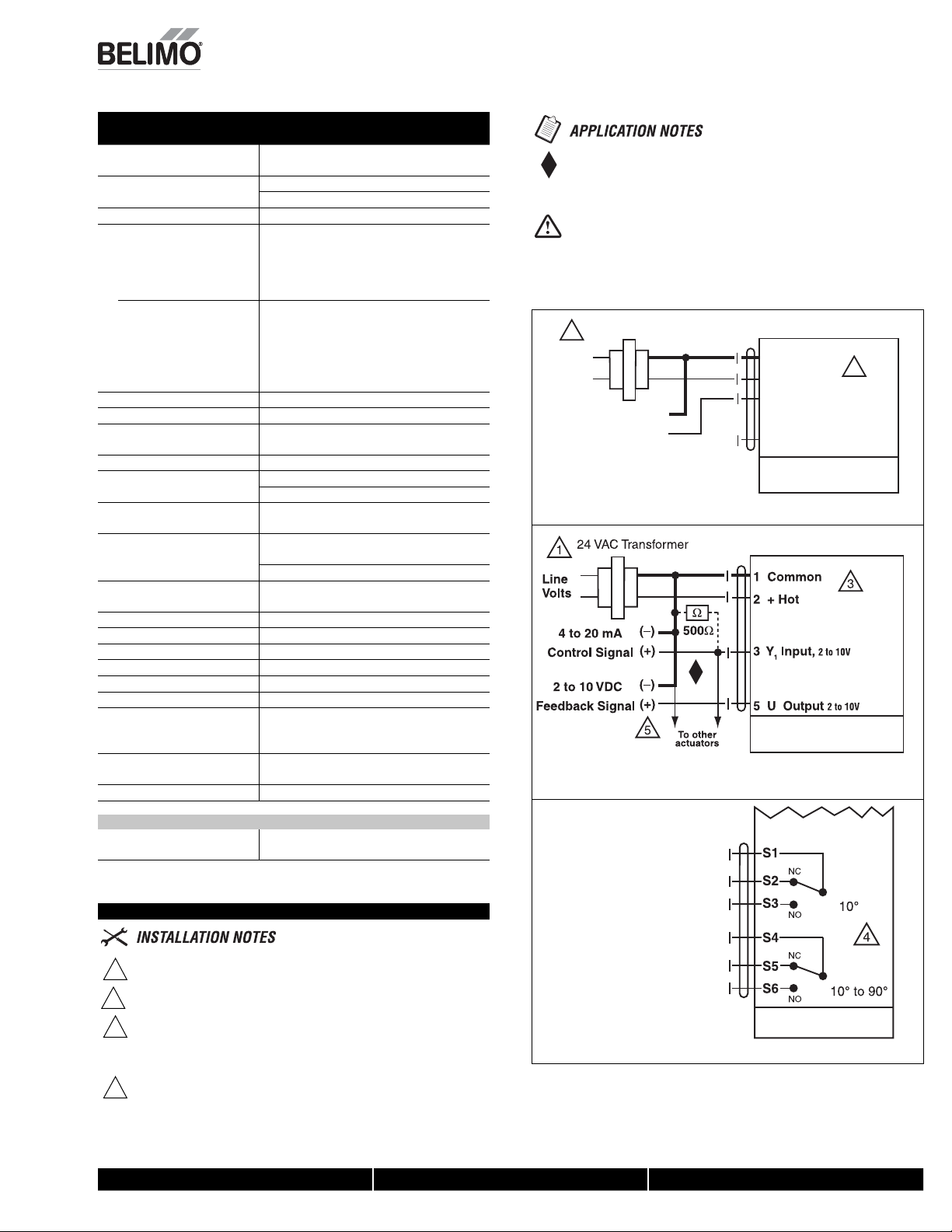
The ZG-R01 500 Ω resistor converts the 4 to 20 mA control signal to
2 to 10 VDC.
WARNING Live Electrical Components!
During installation, testing, servicing and troubleshooting of this product, it may be
necessary to work with live electrical components. Have a qualifi ed licensed electrician or other
individual who has been properly trained in handling live electrical components perform these
tasks. Failure to follow all electrical safety precautions when exposed to live electrical components could result in death or serious injury.
24 VAC Transformer
1
Line
Volts
Control Signal
2 to 10 VDC
(–)
(+)
2 to 10 VDC control of AFRB24-SR and AFRX24-SR
4 to 20 mA control of AFRB24-SR and AFRX24-SR with
2 to 10 VDC feedback output
1 Common
2 + Hot
3 Y1 Input,
5 U Output 2 to 10V
AFRB24-SR, AFRB24-SR-S
AFRX24-SR, AFRX24-SR-S
AFRB24-SR, AFRB24-SR-S
AFRX24-SR, AFRX24-SR-S
3
2 to 10V
W068_AFRB(X)24-SR
W069_AFRB(X)24-SR
Wiring Diagrams
08/10 - Subject to change. © Belimo Aircontrols (USA), Inc.
Provide overload protection and disconnect as required.
1
Actuator may also be powered by 24 VDC.
3
For end position indication, interlock control, fan startup, etc., AFRB24-SR-S
4
and AFRX24-SR-S incorporates two built-in auxiliary switches: 2 x SPDT,
3A (0.5A) @250 VAC, UL Approved, one switch is fi xed at +10°, one is
adjustable 10° to 90°.
Only connect common to neg. (–) leg of control circuits
5
800-543-9038 USA 866-805-7089 CANADA 203-791-8396 LATIN AMERICA
W064_AFRB(X)24_SR_-S
AFRB24-SR-S
AFRX24-SR-S
Auxiliary switches for AFRB24-SR-S, AFRX24-SR-S
1
Page 2
AFRB24-SR, AFRB24-SR-S, AFRX24-SR, AFRX24-SR-S
.9
.8
.7
.9
.8
.7
Y= 0Y= 0
.2
.4
.6
.8
.9
.8
.7
.6
.5
.4
.3
.2
Proportional, Spring Return, 24 V, for 2 to 10 VDC to 4 to 20 mA Control Signal
'$
1
4
3
'0
1
4
3
2
A-AB= 0%
B-AB=100%
AB
A
33 ... 100%
2
A-AB=100%
B
B-AB= 0%
FO FC
AB
B
A
08/10 - Subject to change. © Belimo Aircontrols (USA), Inc.
2
800-543-9038 USA 866-805-7089 CANADA 203-791-8396 LATIN AMERICA
 Loading...