


FJH-2

1
Preface
Thank you for choosing 2KW air parking heater.
This instruction book describes the structures, working
principles, installation and operation of the air-heating parking
heater. For correct use of the heater, please read this instruction
book carefully before installation and use. The instruction book
shall be saved in a convenient place for later reference.
Attention:
● This instruction book is subject to revision without notice,
but the instruction book is in conformity to the purchased
product.
● Our effort is to explain all questions the users may have
through this instruction book. If you have any doubts or find
anything incorrect in this instruction book, please contact
our company directly.
● At first unpacking, please check the heater and its
accessories against the packing list. Please contact the dealer
immediately if any problem is found.
● If any trouble arises during application, please contact the
Department of Marketing of our company or other customer
service stations authorized by this company. We shall do our
best to provide service to you.

2
CONTENTS
1 Introduction „„„„„„„„„„„„„„„„„„3
2 Main Technical Specifications „„„„„„„„„„„3
3 Structures and Working Principles „„„„„„„„„4
4 Installation „„„„„„„„„„„„„„„„„„9
5 Methods of Operation „„„„„„„„„„„„„„20
6 Treatment of Usual Troubles „„„„„„„„„„„28
7 Precautions „„„„„„„„„„„„„„„„„„29
Note:
Comply with the operational manual for installation and
use to ensure that the heaters can work for a long time.
Version No.:20121204
3
1 Introduction
The main equipment of Model
FJH-2/ □ air parking heater
(hereinafter referred to as the heater)
is a small fuel furnace controlled by a
single-chip micro- processor. Its
furnace body (the heat exchanger) is
located in the hood-shape case, which
serves as independent air passage.
Cold air is sucked into the air passage
by the heat supplying fan and blown
out when it becomes hot, so as to
form another heating system that is
independent to the original heating
system of the vehicles. In such a way,
heat can be supplied by the heater to driver’s cab and passengers’
compartment no matter the engine is working or not working. The
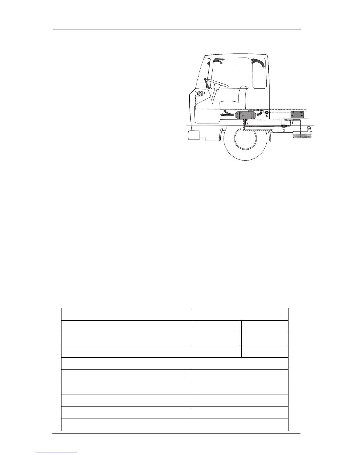
schematic diagram is shown in Fig. 1.
The heater is fully automatically controlled. It features in compact
structure, easy installation, energy-saving, environmental protection, safety
and reliability, easy maintenance, etc.
2 Main Technical Specifications
Please refer to Table 1 for main technical specifications.
Table 1
Heat Power (W)
2000
Fuel
Gasoline
Diesel
Rated Voltage
12V/24V
12V/24V
Fuel Consumption
0.14~0.27
0.12~0.24
Rated Power Consumption (W)
14~29
Working (Environment) Temperature
-40℃~+20℃
Weight of Main Heater (kg)
2.6
Dimensions (mm)
323×120×1 21
Mobile phone control(Optional)
No limitation
Remote control(Optional)
Without obstacles≤800m
Fig. 1
1-Control switch 2- Heater
3- Fuel pump 4- Reducing T 5- Fuse box
4
3 Structures and Working Principles
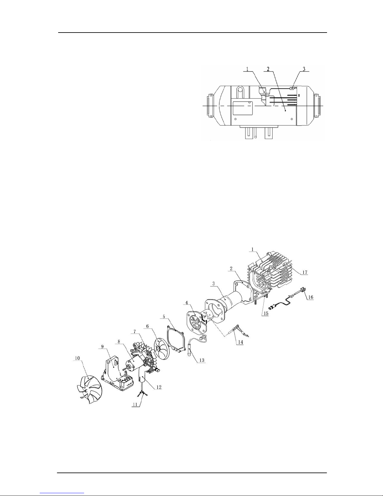
The structures of the main heater are shown in Fig. 2
3.1 Heater
Fig.3 is the diagram for structure
of the heater.
Heat exchanger 1 is the combustion
furnace body, made of die-casting
aluminum, with radiating fins around
and at the rear end. Combustion pipe 3 is
installed in the inner cavity. The front of
the combustion pipe insert the
combustor 4, Fuel comes to the
combustor core through the fuel pipe 13
and is ignited by the glow plug 14 after atomization. The flame enters the gap
between the inner walls of the furnace body through the rear-end guide pipe of
the combustion pipe,The exhaust is discharged through exhaust pipe vent 15.
The fresh air for supporting combustion of the furnace comes from the
supporting air inlet port 12 and is sent to the combustion pipe by the
combustion supporting air blades 6 of the fan motor.
Fig. 3
1- Heat exchanger 2-Gasket 3- Combustion pipe 4-Combustor 5- Gasket
6- Combustion supporting fan blades 7-Bracket for fan motor 8- Fan motor
9-Controller 10- Blade wheel of heating fan 11-Fuel pump leading wire
12- Insulating mat 13- Fuel pipe 14-Glow plug 15- Exhaust pipe vent
16- Overheat sensor 17-Insulating mat
Fig. 2
1-Heater; 2-Hood-shape case;
3-Insulating mat
5
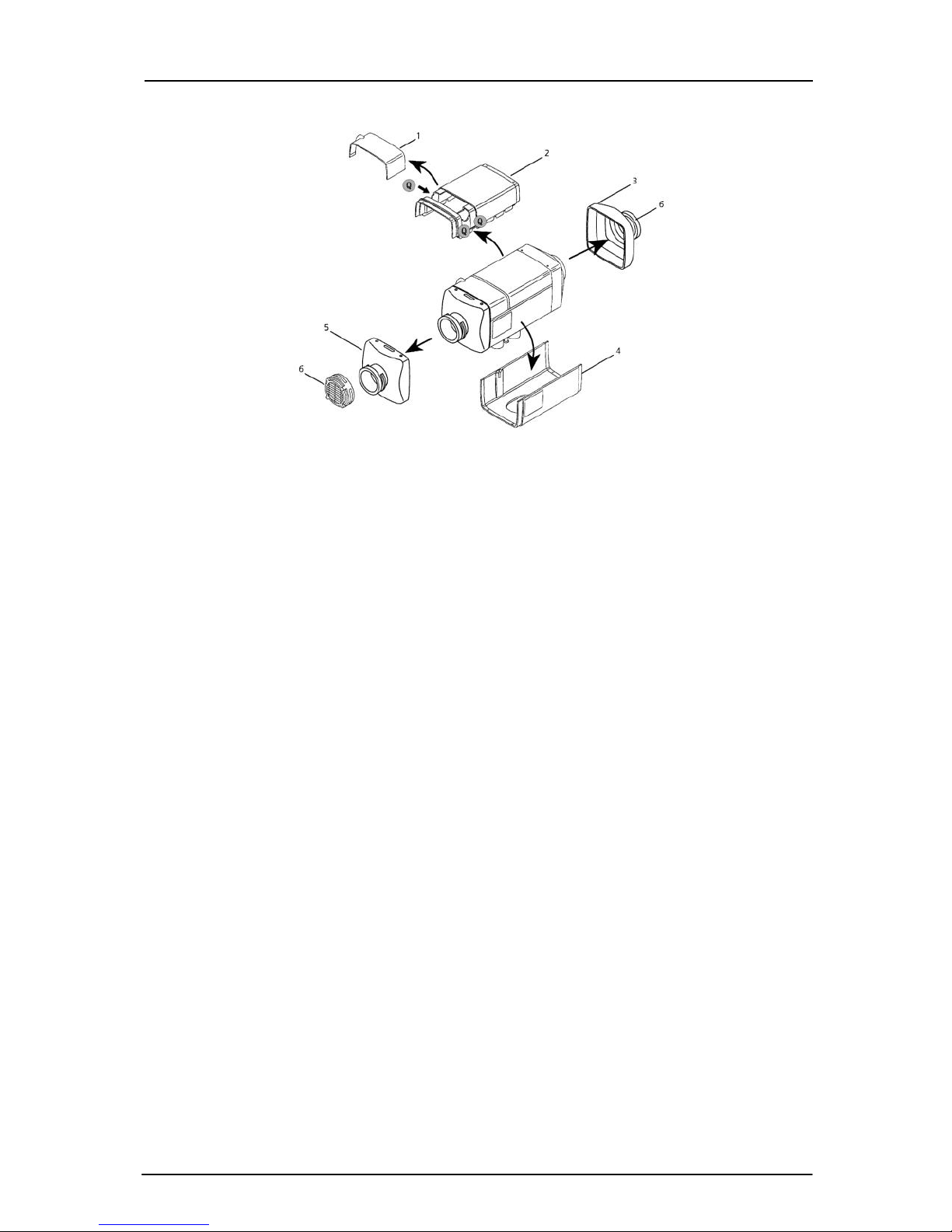
3.2 Hood-Shape Case
Fig. 4
1-Junction box cover 2-Top hood-shape cover 3-Hot air outlet;
4-Bottom hood-shape cover 5-Air inlet of heater 6-Air inlet/exhaust hood
The structure of the hood-shape case is shown in Fig. 4. It consists of
the top cover 2 (The junction box cover 1 can be fixed on its window),
bottom cover 4, air inlet hood 6, air inlet of heater 5 and hot air outlet 3.
They form an air heating passage. Blade wheel of heating fan (Fig.3-10) on
the fan motor (the same fan for supporting combustion) sucks in cold air
from the air inlet. The air is heated by the heat exchanger and sent out from
the hot air outlet.
3.3 Controller
The controller (Fig. 3-9) is at the front of the heaer and the back of the
blade wheel of heating fan.This controller main including collect the
circuit and exam the temperature circuit of the signal of a single-chip
microprocessor、drive circuit、frequency、rotational speed、voltage.Have
the function of heating process automation 、 system surveillance
automation、breakdown handling automation.
3.3.1 Control of Working Procedures
Adjustment and control on operational status are performed during the
whole working cycle (start-operation-stop) of heater in terms of the rotation
speed of fan motor, the frequencies of fuel pump, on-off of glow plug, to
given time sequence and in consideration of the preset value and measured
value of the temperature of the temperature control point, rotation speed of
fan motor feedback signal、frequency of fuel pump, surface temperature
of the heat exchanger and other random parameters.

6
3.3.2 Locking Due to Troubles
When the heater can not be ignited normally, or can not sustain normal
combustion after ignition, or broken circuit or short-circuit occurs to the
glow plug, fan motor, fuel pump, or various sensors and components, or in
case of overheating of heat exchanger, five times of termination of
combustion, twice of unsuccessful ignition or abnormal power voltage, the
heater will turn off and enter into locked status for protection.
3.3.3 Display of Troubles
For convenience of maintenance and repair, troubles of the heater can
be displayed by the indicators (green LED) of the control switch.
In trouble status, indicator flashes at different frequencies. During the
period between two fast flashes, there will be a few times of 1.3Hz slow flashes.
The times of slow flashes represent the types of troubles, as shown in Table 2.
Table 2
Times of flashes
of LED
Cause of trouble
1
Failure of second start
2
Termination of the third time of combustion
3
Power voltage out of specified range
4
The temperature of the glow plug goes up slowly
6
Broken circuit or short-circuit of temperature sensor
7
Broken circuit or short-circuit of fuel pump
8
Broken circuit, short-circuit, or rotation clogging of fan motor
9
Broken circuit or short-circuit of glow plug
10
Overheated
11
Broken circuit or short-circuit of overheating sensor
12
Broken circuit or short-circuit of control switch
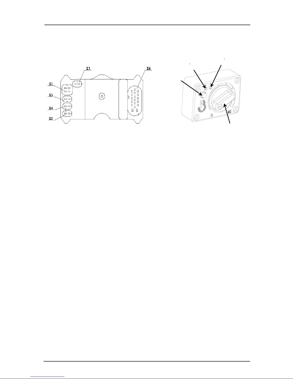
3.3.4 Circuit Interfaces
The following circuit interfaces can be found on the controller case:
socket X1 for fan motor, socket X2 for glow plug, socket X3 for
overheating sensor, socket X4 for the leads to fuel pump and socket X7 for
the main wire bundle. Please refer to Fig. 5 for their locations.
The connection parts are designed with such structures that wrong
connection is made impossible.
3.4 Sensors and Safety Protection
3.4.1 Overheating Sensor
The overheating sensor(Fig.3-16) is installed on the back outer wall of
7
the heat exchanger. If the temperature here becomes higher than 182℃, the
fuel pump circuit will be cut off by the controller and supply of fuel is
stopped and then the heater is turned off for purpose of overheating
protection.
Fig. 5 Fig. 6
1-Control Knob 2-Mode-transformation button
3-Mode indicating light 4-Working indicating light
3.4.2 Temperature Sensor
The temperature sensor is installed on the air inlet of heater,it measures
the air temperature at the air inlet.
The working status and output power of the combustion furnace is
regulated by the controller based on the measured temperature.
3.5 Control Switches
The control switch is shown in Fig. 6. Its control knob is used for the
following operations: turning on or off of the heater and eliminating locking of
the heater due to trouble interrupt and converting from constant temperature
working mode to constant power working mode through the mode conversion
button.
Constant temperature mode: when the indicating light turns red. Use
the control knob to set the control temperature of the heated area(adjustable
continuously from 5℃to 35℃).
Constant power mode:When the indicating light turns green,then use
the control knob adjust the power.( adjustable continuously between 1KW
and 2KW).
Constant lighting of the indicator (green) on the control switch
indicates normal operation of the heater. Flashing of the indicator indicates
trouble status of the heater (see Section 3.3.3 for details).
3.6 Power Supply
The power supply to the heater is a common power source for the engine
of the vehicle, but with an independent safety device. When the power
2
1
8
voltage is lower than the specified lower limit for 18 seconds continuously or
higher than the specified higher limit for 5 seconds continuously, trouble
display will occur to the heater and the heater will be turned off automatically
with trouble display.
3.7 Fuel Supply
The fuel for the heater can be from the fuel tank or from another
independent fuel tank. A special-purpose fuel pump is used for transmission
of fuel and regulation of supply quantity of fuel.
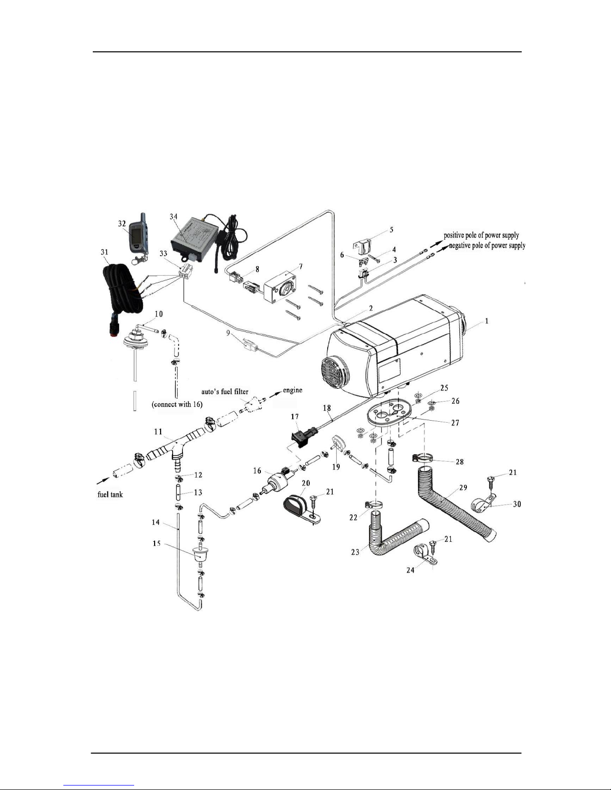
Fig. 7
1-Heater 2-Main wire bundle 3-Fuse holder 4-Self tapping screw 5-Fuse box cover 6-Fuse
7-Control switch 8-Connector X9 for control switch 9-Trouble diagnosis connector 10-Fuel suction
pipe 11-Reducing T 12-Fuel pipe clamp 13-Fuel pip joint 14-Fuel pipe 15-Fuel filter 16-Fuel
pump 17-Fuel pump connector 18-Fuel pump leading wire 19-Damper 20-Fuel pump clamp
21-Self drilling tapping screw 22-Air inlet pipe clamp 23-Air inlet pipe 24-Air inlet pipe fixing clamp
25-Nut M6 26-Washer 27-Gasket 28-Exhuat pipe clamp 29-Exhaust pipe 30-Exhaust pipe fixing
clamp 31-Manual button 32-Remote controller 33-Plug of remote control receiver or GSM receiver
34-Remote control receiver or GSM receiver

9
4 Installation
Only special-purpose parts can be used for installation of the heater.
Fig. 7 is the diagram for installation. The positions and ways of fixing of
various parts may vary from one automobile model to another, but the
general principles must be followed in conformity with the requirements of
this chapter. Otherwise the heater may not work normally or safety
problems may occur.
4.1 Requirements for Installation and Places of Application of the Heater
4.1.1 It is not allowed to use the heater in locations with inflammable or
explosive substances such as flammable gas or flammable dust.
4.1.2 It is not allowed to use the heater in closed space (such as garage or
maintenance workshop without air ventilation) to avoid danger of poisoning
due to exhaust from burning.
Attention: Under either of the above circumstances, it is not allowed to use
the heater even at the timer stand-by state or wireless remote control state.
4.1.3 It is not allowed to install and use the heater in bedrooms.
4.1.4 If the heater is installed in special-purpose vehicles (such as vehicles for
dangerous goods), special rules must be followed in installing the heater.
4.1.5 Never place fuel tank, compression tank, fire extinguisher, clothes,
paper, etc. near the heater or opposite to the hot air vent.
4.2 Installation of the Main Heater
4.2.1The main heater can be installed inside the vehicle or outside the
vehicle. But when it is installed outside the vehicle a shield which can be
prevent the damage(splash of stones)of external force(supplied by
retailers).The heater can’t be soaked in the water or in the rain for a long
time(heater should be shut off).The heater should be operated after it is
completely dried if the heater is corroded by rain and water.
4.2.2 For convenience of heating air flow and installation, maintenance of the
main heater, enough space must be provided for installation. Please refer to
the scope of double dot line for the space for installation, as shown in Fig. 8.
10
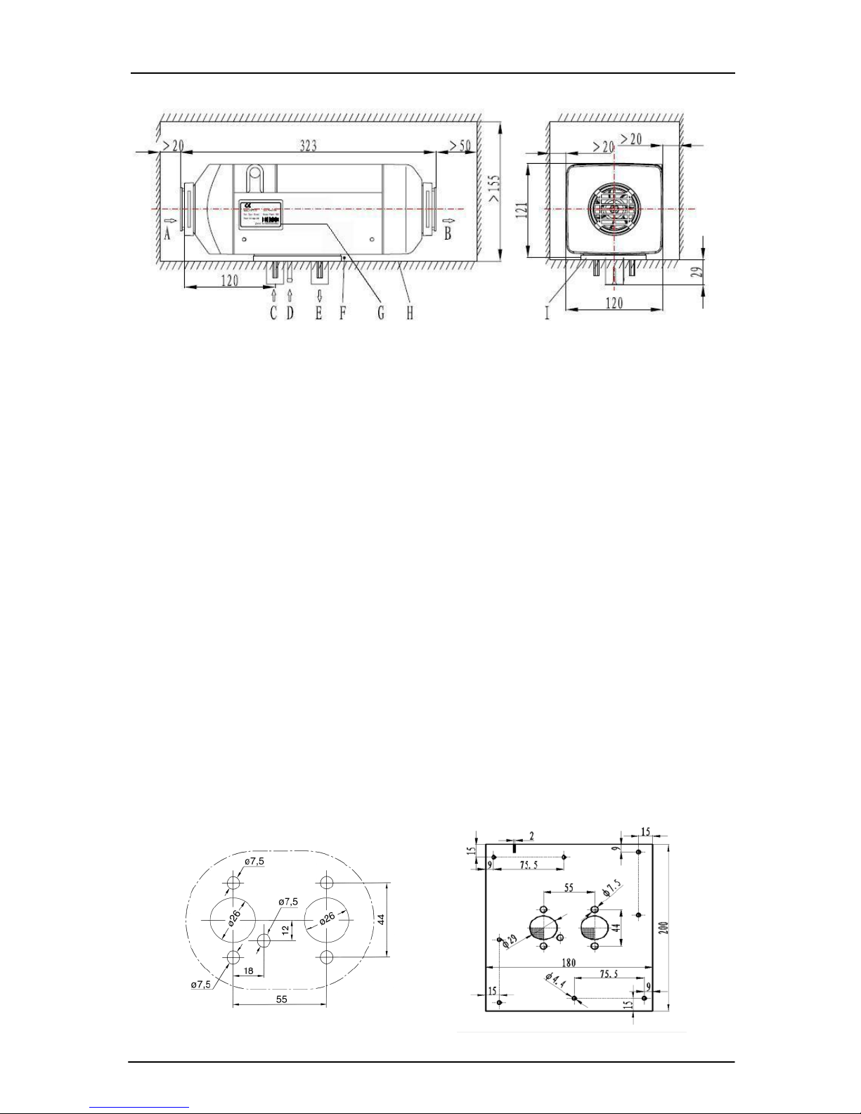
Fig. 8
A-Inlet of heating air B-Outlet of heated air C-Inlet of combustion air
D- Fuel inlet E-Exhaust outlet F- Non-interference area
G-Information label H-Installation surface I-Gasket
Please make sure that there is not any foreign matter in the gap
between the bottom surface of the main heater and the installation surface
of the vehicle (Fig. 8-F).
4.2.3 Good sealing is necessary between the main heater and the installation
surface on the vehicle. A special gasket (as shown in Fig. 8) supplied by the
manufacturer must inserted in between during installation. The installation
surface must be even enough. Its parts at the installation bases of the main
heater shall have unevenness of less than 1mm. After drilling installation
holes, evenness must be improved according to this requirement. At
installation, please rotate the four M6 nuts, provided by the manufacturer,
tight. The torque for tightening shall be 6Nm+1Nm.
Please refer to Fig. 9 for positions of installation holes.
4.2.4If the sickness of the installation panel<1.5mm a mounting plate may
need(Fig.10).
Fig.9
Fig.10
 Loading...