

Page 1

User Manual
Installation
Open Dual-Band Industrial Access-Point / Client / Access-
Bridge
OpenBAT-Family: BAT-F
Installation BAT-F
Release 17 12/2019
Technical support
https://hirschmann-support.belden.com
Page 2

The naming of copyrighted trademarks in this manual, even when not specially indicated, should
not be taken to mean that these names may be considered as free in the sense of the trademark
and tradename protection law and hence that they may be freely used by anyone.
© 2019 Hirschmann Automation and Control GmbH
Manuals and software are protected by copyright. All rights reserved. The copying, reproduction,
translation, conversion into any electronic medium or machine scannable form is not permitted,
either in whole or in part. An exception is the preparation of a backup copy of the software for
your own use.
The performance features described here are binding only if they have been expressly agreed
when the contract was made. This document was produced by Hirschmann Automation and
Control GmbH according to the best of the company's knowledge. Hirschmann reserves the right
to change the contents of this document without prior notice. Hirschmann can give no guarantee
in respect of the correctness or accuracy of the information in this document.
Hirschmann can accept no responsibility for damages, resulting from the use of the network
components or the associated operating software. In addition, we refer to the conditions of use
specified in the license contract.
You can get the latest version of this manual on the Internet at the Hirschmann product site
(www.hirschmann.com).
Hirschmann Automation and Control GmbH
Stuttgarter Str. 45-51
72654 Neckartenzlingen
Germany
04.12.2019
Installation BAT-F
Release 17 12/2019
Page 3

Contents
Safety instructions 6
About this manual 23
Key 24
1 Description 25
1.1 General description 25
1.2 Device name and product code 26
1.3 Device view 30
1.4 Power supply 32
1.4.1 Supply voltage with the characteristic value C
(24 V DC ... 48 V DC) 32
1.4.2 Supply voltage with the characteristic value K
(60 V DC ... 250 V DC / 110 V AC ... 230 V AC,
50 Hz ... 60 Hz) 32
1.4.3 Supply voltage with the characteristic value P (Power
supply only through PoE) 32
1.4.4 Supply voltage with the characteristic value W
(24 V DC) 33
1.5 Ethernet ports 33
1.5.1 Gigabit combo port 33
1.5.2 10/100/1000 Mbit/s twisted-pair connection (optional) 34
1.5.3 Pin assignments 34
1.6 Connections for antennas 36
1.7 Display elements 36
1.7.1 Meaning of the LEDs 36
1.7.2 Device state 37
1.7.3 Port status 37
1.8 Management interfaces 38
1.8.1 V.24 interface (external management) 38
1.8.2 USB interface 40
1.9 Signal contact 40
1.10 Reset button 41
Installation BAT-F
Release 17 12/2019
3
Page 4

2 Installation 42
2.1 Checking the package contents 42
2.2 Installing and grounding the device 42
2.2.1 Installing the device onto or on a flat surface 42
2.2.2 Installing the device on a pole 43
2.2.3 Grounding the device 43
2.3 Installing an SFP transceiver (optional) 44
2.4 Installing the antennas 44
2.5 Connecting the power supply and the signal contact lines 45
2.5.1 Supply voltage with the characteristic value C
(24 V DC ... 48 V DC) 46
2.5.2 Supply voltage with the characteristic value K
(60 V DC ... 250 V DC / 110 V AC ... 230 V AC,
50 Hz ... 60 Hz) 46
2.5.3 Supply voltage with the characteristic value W
(24 V DC) 47
2.5.4 Signal contact 48
2.6 Operating the device 48
2.6.1 Connecting the power supply through a 7/8"
connector 49
2.6.2 Connecting the power supply through PoE 49
2.7 Connecting data cables 49
2.7.1 Gigabit combo port 49
2.7.2 10/100/1000 Mbit/s twisted-pair connection (optional) 50
3 Making basic settings 51
4 First login (Password change) 52
5 Obtain compliance for operation in the European
Union 53
6 Configuring the transmit power 56
7 Maintenance and service 58
8Disassembly 59
8.1 Removing the device 59
Installation BAT-F
4
Release 17 12/2019
Page 5

8.2 Removing an SFP transceiver (optional) 59
9 Technical data 60
9.1 General technical data 60
9.2 Dimension drawings 62
9.3 Radio technology 65
9.4 Roaming 65
9.5 Receiving sensitivity, transmit power, and data rate of the
WLAN module version EWLAN1 (Approvals 2, characteristic
value M or 9) 66
9.5.1 IEEE 802.11b 66
9.5.2 IEEE 802.11g 66
9.5.3 IEEE 802.11a 66
9.5.4 IEEE 802.11n 67
9.6 Receiving sensitivity, transmit power, and data rate of the
WLAN module version EWLAN2 for high-gain antennas
(Approvals 2, characteristic value H) 69
9.6.1 IEEE 802.11b 69
9.6.2 IEEE 802.11g 69
9.6.3 IEEE 802.11a 69
9.6.4 IEEE 802.11n 70
9.7 EMC and immunity 72
9.8 Network range 73
9.9 Power consumption/power output 74
10 Scope of delivery, order numbers and
accessories 75
11 Underlying technical standards 78
A Further support 80
Installation BAT-F
Release 17 12/2019
5
Page 6

Safety instructions
WARNING
UNCONTROLLED MACHINE ACTIONS
To avoid uncontrolled machine actions caused by data loss, configure all
the data transmission devices individually.
Before you start any machine which is controlled via data transmission, be
sure to complete the configuration of all data transmission devices.
Failure to follow this instruction can result in death, serious injury, or
equipment damage.
General safety instructions
You operate this device with electricity. Improper usage of the device
entails the risk of physical injury or significant property damage. The
proper and safe operation of this device depends on proper handling
during transportation, proper storage and installation, and careful
operation and maintenance procedures.
Before connecting any cable, read this document, and the safety
instructions and warnings.
Operate the device with undamaged components exclusively.
The device is free of any service components. In case of a damaged
or malfunctioning device, turn off the supply voltage and return the
device to Hirschmann for inspection.
Internal fuses are triggered only in the case of a detected error in the
device. In case of damage or malfunction of the device, turn off the
supply voltage and return the device to the plant for inspection.
Certified usage
Use the product only for the application cases described in the
Hirschmann product information, including this manual.
Operate the product only according to the technical specifications.
See “Technical data” on page 60.
Connect to the product only components suitable for the requirements
of the specific application case.
Installation site requirements
Restricted access location:
The location is outside the operator access area.
The location is accessible to the service personnel even when the
device is switched on.
Installation BAT-F
6
Release 17 12/2019
Page 7

Indoor operator access area:
The location is accessible without tools.
The person responsible for the area has provided access for the
operator intentionally.
The operator knows of the access possibilities, regardless of whether
they need a tool.
If all the following requirements are fulfilled, you have the option of
installing the device in the indoor operator access area.
You supply 24 V DC to 48 V DC SELV voltage to the device.
You install the device inside a building.
The surrounding air temperature is 140 °F (60 °C).
Applies exclusively for Finland, Norway, and Sweden:
You supply Power over Ethernet (PoE) to the device, with the PoE
data cable laid inside a building exclusively.
In any case, install this device in a switch cabinet or in an operating
site with restricted access, to which maintenance staff have exclusive
access if 1 of the following requirements is fulfilled:
You supply 60 V DC to 250 V DC or 110 V AC to 230 V AC to the
device.
You install the device outside a building.
The surrounding air temperature is > 140 °F (60 °C).
Applies exclusively for Finland, Norway, and Sweden:
You supply Power over Ethernet (PoE) to the device, with the PoE
data cable laid outside a building or between buildings.
Applies to device variants featuring supply voltage with characteristic
value K: (60 V DC ... 250 V DC / 110 V AC ... 230 V AC, 50 Hz ...
60 Hz):
See “Device name and product code” on page 26.
Install this device solely in a switch cabinet or in an operating site with
restricted access, to which maintenance staff have exclusive access.
Device casing
Only technicians authorized by the manufacturer are permitted to open
the casing.
Install the device in the vertical position, with the antenna connections
pointing upwards.
At ambient air temperatures > 140 °F (+60 °C):
The surfaces of the device housing may become hot. Avoid touching
the device while it is operating.
Qualification requirements for personnel
Only allow qualified personnel to work on the device.
Installation BAT-F
Release 17 12/2019
7
Page 8

Qualified personnel have the following characteristics:
Qualified personnel are properly trained. Training as well as practical
knowledge and experience make up their qualifications. This is the
prerequisite for grounding and labeling circuits, devices, and systems
in accordance with current standards in safety technology.
Qualified personnel are aware of the dangers that exist in their work.
Qualified personnel are familiar with appropriate measures against
these hazards in order to reduce the risk for themselves and others.
Qualified personnel receive training on a regular basis.
National and international safety regulations
Verify that the electrical installation meets local or nationally applicable
safety regulations.
When installing antennas, observe the regulations of the country in
which you are operating the WLAN device with regard to the general
operating permission and the maximum emission levels.
Install and operate this equipment with a minimum distance of
19.7 inches (50 cm) between the antenna and your body.
Grounding the device
Grounding the device is by means of a separate ground connection on the
device.
Ground the device before connecting any other cables.
Disconnect the grounding only after disconnecting all other cables.
The overall shield of a connected shielded twisted pair cable is connected
to the ground connection on the metal housing as a conductor.
Lightning protection
Refer to the information in the “WLAN Outdoor Guide” on “Lightning
and overvoltage protection”.
The manual is available for download on the Internet: https://
www.doc.hirschmann.com
Install over voltage protector devices on every outdoor Ethernet cable.
Protect antennas installed outside with lightning protection devices (for
example lightning conductors).
Take lightning protection measures which mitigate the effects of
lightning strikes.
The installation of the device occurs in accordance with valid
standards (such as VDE 0185 and IEC 62305), and in accordance
with the lightning protection procedures recognized and proven for the
application and the environment.
Installation BAT-F
8
Release 17 12/2019
Page 9

Requirements for connecting electrical wires
Before connecting the electrical wires, always verify that the
requirements listed are complied with.
The following requirements apply without restrictions:
The electrical wires are voltage-free.
The cables used are permitted for the temperature range of the application case.
Relevant for North America:
The power supply cables are suitable for ambient air temperatures of at least 167 °F
(75 °C). The power supply cable wires are made of copper.
Table 1: Requirements for connecting electrical wires
Requirements for connecting the supply voltage
The following requirements apply without restrictions:
All variants All of the following requirements are complied with:
The supply voltage corresponds to the voltage specified on the type
plate of the device.
The power supply conforms to overvoltage category I or II.
The power supply has an easily accessible disconnecting device (for
example a switch or a plug). This disconnecting device is clearly
identified. So in the case of an emergency, it is clear which
disconnecting device belongs to which power supply cable.
The cross-section of the ground conductor is the same size as or
bigger than the cross-section of the power supply cables.
Table 2: Requirements for connecting the supply voltage
Installation BAT-F
Release 17 12/2019
9
Page 10

The following requirements apply without restrictions:
Only for device
variants featuring
supply voltage with
characteristic
value C (24 V DC ...
48 V DC) or W
(24 V DC):
Only for device
variants featuring
supply voltage with
characteristic
value K (60 V DC ...
250 V DC /
110 V AC ...
230 V AC, 50 Hz ...
60 Hz):
The wire diameter of the power supply cable is at least 1 mm² (North
America: AWG16) on the supply voltage input.
The following requirements are alternatively complied with:
Alternative 1 The power supply complies with the requirements
for a limited power source (LPS) as per EN 60950-1.
Alternative 2 Relevant for North America:
The power supply complies with the requirements
according to NEC Class 2.
Alternative 3 All of the following requirements are complied with:
The power supply complies with the
requirements for a safety extra-low voltage
(SELV) as per IEC/EN 60950-1.
A fuse suitable for DC voltage is located in the
plus conductor of the power supply.
The minus conductor is on ground potential.
Otherwise, a fuse is also located in the minus
conductor.
Regarding the properties of this fuse:
See “General technical data” on page 60.
All of the following requirements are complied with:
Supply with DC voltage:
A fuse suitable for DC voltage is located in the plus conductor of the
power supply.
The minus conductor is on ground potential. Otherwise, a fuse is also
located in the minus conductor.
Regarding the properties of this fuse:
See “General technical data” on page 60.
The wire diameter of the power supply cable is at least 1 mm² (North
America: AWG16) on the supply voltage input.
Supply with AC voltage:
A fuse is located in the outer conductor of the power supply.
The neutral conductor is on ground potential at both voltage inputs.
Otherwise, a fuse is also located in the neutral conductor.
Regarding the properties of this fuse:
See “General technical data” on page 60.
The wire diameter of the power supply cable is at least 0.75 mm²
(North America: AWG18) on the supply voltage input.
Table 2: Requirements for connecting the supply voltage
10
Installation BAT-F
Release 17 12/2019
Page 11

ATEX directive 2014/34/EU – specific regulations for safe
operation
In Ex zone 2, only devices with a corresponding label may be operated.
When operating the BAT-F types with characteristic value G for
Approvals 1 (ATEX zone 2), the following applies:
Never use the supply voltage with characteristic value K (60 V DC ...
250 V DC / 110 V AC ... 230 V AC, 50 Hz ... 60 Hz) in Ex zone 2.
II 3 G Ex nA IIC T4 Gc DEKRA 13ATEX0153 X
40 °F ... +158 °F (40 °C ... +70 °C) for temperature range
characteristic value T and E
+32 °F ... +140 °F (0 °C ... +60 °C) for temperature range
characteristic value S
Temperature code T4 Ambient temperature 40 °F ... +158 °F (40 °C ... +70 °C ;
temperature range with characteristic value T and E)
Ambient temperature +32 °F ... +140 °F (0 °C ... +60 °C;
temperature range with characteristic value S)
List of standards EN 60079-0:2012 + A11
EN 60079-15:2010
DO NOT OPEN THE DEVICE WHEN IT IS ELECTRICALLY CHARGED.
THE USB CONNECTOR MUST NOT BE USED WHEN THE DEVICE IS
OPERATED IN EXPLOSIVE HAZARDOUS LOCATIONS.
Special conditions for safe use
For supply voltage with characteristic value C (24 V DC ... 48 V DC)
and W (24 V DC):
Provisions shall be made to prevent the rated voltage from being
exceeded by transient disturbances of more than 119 V.
When the temperature under rated conditions exceeds 158 °F (70 °C)
at the cable or conduit entry point, or 176 °F (80 °C) at the branching
point of the conductors, take care that the temperature specification of
the selected cable is in compliance with the actual measured
temperature values.
Install the modules in a suitable enclosure in accordance with
EN 60079-15 providing a degree of protection of at least IP54
according to EN 60529, taking into account the environmental
conditions under which the equipment will be used.
Relevant for use in explosion hazard areas (Hazardous
Locations, Class I, Division 2):
In Ex zone 2, only the devices with a corresponding label may be
operated in explosion hazard areas Class I, Division 2.
Installation BAT-F
Release 17 12/2019
11
Page 12

When operating the BAT-F types in explosion hazard areas Class I,
Division 2, the following applies:
Class I, Div. 2 Goups A, B, C and D
Temperature code T4 Ambient: 40 °F ... +158 °F (40 °C ... +70 °C; for
characteristic value T and E for temperature range)
Ambient: +32 °F ... +140 °F (0 °C ... +60 °C; for characteristic
value S for temperature range)
List of standards FM3600,
FM3611
DO NOT OPEN THE DEVICE WHEN IT IS ELECTRICALLY CHARGED.
Use this device only with the impact protection.
WARNING
EXPLOSION HAZARD
Do not disconnect or open equipment unless power has been switched off
or the area is known to be non-hazardous.
Failure to follow this instruction can result in death, serious injury, or
equipment damage.
AVERTISSEMENT
RISQUE D'EXPLOSION
Ne pas debrancher ou ouvrir tant que le circuit est sous tension, a moins
qu'il ne s'agisse d'un emplacement non dangereux.
Le non-respect de ces instructions peut entraîner des blessures
graves, voire mortelles ainsi que des dégâts matériels.
12
Installation BAT-F
Release 17 12/2019
Page 13

CONTROL DRAWING for BAT-F devices according to
Class 1, Division 2 Hazardous Locations or according to the
European Directive 2014/34/EU
Rev.: 0 Document No.: 000183360DNR
Ordinary Location,
Non-Hazardous Area,
Non-Explosive Atmosphere
Zone 2
Explosive Atmosphere
Class 1, Division 2
Groups A, B, C, D
Hazardous Location
or
Relay contacts. Equipment with
non-incendive field wiring parameters.
Polarity is not relevant.
THE RELAY TERMINALS ARE
DEPENDENT UPON THE FOLLOWING
ENTITY PARAMETERS:
V
max
or l
max
or I
i
C
i
L
i
30 V 90 mA 2 nF 1 μH
Supply voltage with characteristic value W:
16.8 V DC – 32 V DC;
Ambient Temperature rating:
Ta: 0 °C to +60 °C for temperature range with
characteristic value “S”
Temperature Code: T4
i
U
Supply voltage with characteristic value C:
18 V DC – 60 V DC;
Supply voltage with characteristic value K:
88 V AC – 265 V AC or
48 V DC – 320 V DC
Ta: −40 °C to +70 °C for temperature range
with characteristic value “T” or “E”
(The characteristic value is part of the
type designation on the device.)
Relais
P2
P1
The earth conductor must be at least the
same wire size (mm
2
oder AWG) as the
supply conductors.
BAT-F WLAN-AccessPoint/-Client
page 1 of 2
Installation BAT-F
Release 17 12/2019
13
Page 14

Rev.: 0
page 2 of 2
For Use in Hazardous Locations Class I, Division 2 Groups A, B, C, D:
Only allowed for BAT-F model No’s. which are individually labelled
“FOR USE IN HAZARDOUS LOCATIONS”
Non-incendive field wiring circuits must be wired in accordance with the
National Electrical Code (NEC), NFPA 70 , article 501.
WARNING – EXPLOSION HAZARD – SUBSTITUTION OF ANY
COMPONENTS MAY IMPAIR SUITABILITY FOR HAZARDOUS
LOCATIONS OR EXPLOSIVE ATMOSPHERES.
WARNING – EXPLOSION HAZARD – DO NOT DISCONNECT
EQUIPMENT UNLESS POWER HAS BEEN SWITCHED OFF
OR THE AREA IS KNOWN TO BE NON-HAZARDOUS.
Notes:
The non-incendive field wiring circuit concept allows interconnection of
non-incendive field wiring apparatus and associated nonincendive field wiring
apparatus using any of the wiring methods permitted for unclassified locations
when certain parametric conditions are met.
Capacity: C
a
or C0 ≥ Ci + C
Cable
;
Inductivity: L
a
or L0 ≥ Li + L
Cable
CONTROL DRAWING for BAT-F devices according to
Class 1, Division 2 Hazardous Locations or according to the
European Directive 2014/34/EU
Document No.: 000183360DNR
E
m
a
r
k
i
n
g
T
h
e
l
a
b
e
l
e
d
d
e
v
i
c
e
s
c
o
m
p
l
y
w
it
14
Installation BAT-F
Release 17 12/2019
Page 15

h the regulations contained in the following European directive(s):
Regulation No. 10 of the Economic Commission for Europe of the United
Nations (UN/ECE): Devices with an approval are labeled with the
E type approval mark.
The optical transceivers M-SFP-SX/LC-EEC and M-SFP-LX/LC-EEC can
be used (relevant for devices with approval characteristic value M).
Devices featuring supply voltage with characteristic value C are not
specified for operation during the motor start phase.
CE marking
The labeled devices comply with the regulations contained in the following
European directive(s):
2011/65/EU and 2015/863/EU (RoHS)
Directive of the European Parliament and of the Council on the restriction
of the use of certain hazardous substances in electrical and electronic
equipment.
2014/53/EU (RED)
Directive of the European Parliament and of the council on the
harmonization of the laws of the Member States relating to the making
available on the market of radio equipment.
This product may be operated in all EU (European Union)
countries under the condition that it has been configured correctly.
In accordance with the above-named EU directive(s), the EU conformity
declaration will be available to the relevant authorities at the following
address:
Hirschmann Automation and Control GmbH
Stuttgarter Str. 45-51
72654 Neckartenzlingen
Germany
The product can be used in residential areas (residential, commercial and
light-industrial environments) and in industrial areas.
Installation BAT-F
Release 17 12/2019
15
Page 16

AT
BE
BG
CH
CY
CZ
DE
DK
EE
EL
ES
FI
FR
HR
HU
IE
IT
LI
LT
LU
LV
MT
NL
NO
PL
PT
RO
RS
SE
SI
SK
TR
UK
Notes for countries with the following country codes:
The RED compliance requires compliant operation of the device in the
5 GHz band channels. Compliant operation of the device is achieved
by an unchangeable determination of the country setting. To obtain
RED compliance, perform the work steps described in chapter “Obtain
compliance for operation in the European Union” on page 53.
Applies to the operation of devices in the 5.6 to 5.65 GHz band:
Install an antenna with an antenna gain of at least 3 dBi.
Applies to the operation of devices with antennas having a gain of
more than 8 dBi:
At temperatures lower than 13 °F (25 °C) a power reduction of 4 dB
using a software setting has to be applied. This reduction applies in
addition to the antenna gain setting.
Applies to the operation of antennas having a gain of more than
18 dBi:
For the operation of 5 GHz indoor channels (channels 36 to 64) a
power reduction of 4 dB using a software setting has to be applied.
This reduction applies in addition to the antenna gain setting.
Applies to the operation of the BAT-ANT-N-14G-IP23 antenna:
In addition to the antenna cable supplied, the use of the BAT-CLB-2 N
m-f antenna is required.
See “Accessories” on page 76.
16
Installation BAT-F
Release 17 12/2019
Page 17

Notes for Germany (DE), Ireland (IE), and the United Kingdom (UK):
DE
IE
UK
Operation in the 5.8 GHz band at a radiated power (EIRP) >25 mW is
subject to meeting the following conditions:
Germany (DE)
Frequency range: 5725 MHz to 5875 MHz
Condition: The usage of this band is restricted to commercial public
telecommunication services. Registration at the Federal Network
Agency is required.
Name and website of the competent authority:
Bundesnetzagentur
www.bundesnetzagentur.de
Ireland (IE)
Frequency range: 5725 MHz to 5875 MHz
Condition: Registration of operational base stations
Name and website of the competent authority:
Commission for Communications Regulation
www.comreg.ie
United Kingdom (UK):
Frequency range: 5725 MHz to 5850 MHz
Condition: Light-licensing regime
Name and website of the competent authority:
Ofcom
www.ofcom.org.uk
LED or laser components
LED or LASER components according to IEC 60825-1 (2014):
CLASS 1 LASER PRODUCT
CLASS 1 LED PRODUCT
Installation BAT-F
Release 17 12/2019
17
Page 18

FCC note
Supplier's Declaration of Conformity
47 CFR § 2.1077 Compliance Information
BAT-F
U.S. Contact Information
Belden – St. Louis
1 N. Brentwood Blvd. 15th Floor
St. Louis, Missouri 63105, United States
Phone: 314.854.8000
This device complies with part 15 of the FCC rules.
Operation is subject to the following two conditions:
This device may not cause harmful interference, and
This device must accept any interference received, including
interference that may cause undesired operation.
This equipment has been tested and found to comply with the limits for a
Class B digital device, pursuant to part 15 of the FCC Rules. These limits
are designed to provide reasonable protection against harmful
interference in a residential installation. This equipment generates, uses
and can radiate radio frequency energy and, if not installed and used in
accordance with the instructions, may cause harmful interference to radio
communications. However, there is no guarantee that interference will not
occur in a particular installation. If this equipment does cause harmful
interference to radio or television reception, which can be determined by
turning the equipment off and on, the user is encouraged to try to correct
the interference by one or more of the following measures:
Reposition the receiver antenna or change the angle of the receiver
antenna.
Increase the separation between the device and the receiver.
Connect the device to a different outlet on a different power supply
cable from that to which the receiver is connected.
Consult a specialist retailer or an electronic systems engineer for help.
Changes or modifications not expressly approved by the holder of the
certificate could void the user’s authority to operate this equipment.
EWLAN1 Module
Note for the use in the USA and in Canada
The following section applies to BAT-F variants with the characteristic
value US (USA/Canada) for country approvals which are labeled as
follows:
Contains Transmitter Module
Installation BAT-F
18
Release 17 12/2019
Page 19

FCC ID: U99EWLAN1
IC: 4019A-EWLAN1
This equipment complies with FCC and IC RSS-102 radiation exposure
limits set forth for an uncontrolled environment. Install and operate this
equipment with a minimum distance of 19.7 in (50 cm) (related to a 9 dBi
antenna) between the radiation source and your body.
The antenna used for this transmitter must not be co-located with any
other transmitters within a host device, except in accordance with FCC
multi-transmitter product procedures.
This transmitter is restricted to indoor use only within the
5.15 to 5.25 GHz band to reduce potential for harmful interference to cochannel mobile satellite systems.
The power of the device was reduced by 6 dB on channel 149
(5745 MHz) for all modulations to be compliant to the band edge limits.
This Class B digital apparatus complies with Canadian ICES-003.
Cet appareil numérique de la classe B est conforme à la norme NMB-003
du Canada.
To reduce potential radio interference to other users, the antenna type
and its gain should be so chosen that the equivalent isotropically radiated
power (EIRP) is not more than that permitted for successful
communication.
This device has been designed to operate with the antennas listed below
in point-to-multipoint systems, and having a maximum gain of 9 dBi:
Antenna(s) for operation with this
device:
BAT-ANT-RSMA-2AGN-R
BAT-ANT-N-3AGN-IP67 Yes Yes Yes
BAT-ANT-N-MiMoDB-5N-IP65 Yes Yes Yes
BAT-ANT-N-MiMo5-9N-IP65 No Yes Yes
BAT-ANT-N-8G-DS-IP65 Yes No No
a. Note: When using 3 antennas type BAT-ANT-RSMA-2AGN-R, you must align each antenna
in another spatial direction (x-y-z) so that one antenna is arranged vertically to the device
and the other two antennas are arranged at right angles to each other.
a
Permitted band of operation
2.4 GHz band 5.15 GHz ...
5.25 GHz band
Yes Yes Yes
5.725 GHz ...
5.825 GHz band
The FCC approval is valid only in conjunction with the listed antennas. If
other antennas are used, the approval expires. The responsibility lies with
the operator of the system. The required antenna impedance is 50 .
EWLAN2 Module
Installation BAT-F
Release 17 12/2019
19
Page 20

Note for the use in the USA and in Canada
The following section applies to BAT-F variants with the characteristic
value US (USA/Canada) for country approvals which are labeled as
follows:
Contains Transmitter Module
FCC ID: U99EWLAN2
IC: 4019A-EWLAN2
This equipment complies with FCC and IC RSS-102 radiation exposure
limits set forth for an uncontrolled environment. This equipment should be
installed and operated with minimum distance of 19.7 in (50 cm) (related
to a 18 dBi antenna) between the radiation source and your body.
The antenna used for this transmitter must not be co-located with any
other transmitters within a host device, except in accordance with FCC
multi-transmitter product procedures.
This transmitter is restricted to indoor use only within the
5.15 to 5.25 GHz band to reduce potential for harmful interference to cochannel mobile satellite systems.
This Class B digital apparatus complies with Canadian ICES-003.
Cet appareil numérique de la classe B est conforme à la norme NMB-003
du Canada.
To reduce potential radio interference to other users, the antenna type
and its gain should be so chosen that the equivalent isotropically radiated
power (EIRP) is not more than that permitted for successful
communication.
This device has been designed to operate with the antennas listed below
having a maximum gain of 18 dBi:
Antenna(s) for operation with this
device:
BAT-ANT-RSMA-2AGN-R
BAT-ANT-N-3AGN-IP67 Yes Yes Yes
BAT-ANT-N-MiMoDB-5N-IP65 Yes Yes Yes
BAT-ANT-N-MiMo5-9N-IP65 No Yes Yes
BAT-ANT-N-8G-DS-IP65 Yes No No
BAT-ANT-N-MiMo-18N-IP65
a
b
Permitted band of operation
2.4 GHz band 5.15 GHz ...
5.25 GHz band
Yes Yes Yes
No No Yes
5.725 GHz ...
5.825 GHz band
a. Note: When using 3 antennas type BAT-ANT-RSMA-2AGN-R, you must align each antenna
in another spatial direction (x-y-z) so that one antenna is arranged vertically to the device
and the other two antennas are arranged at right angles to each other.
b. Note: Connect the BAT-ANT-N-MiMo-18N-IP65 to the WLAN module as follows:
Connect the antenna port "Ver" with the WLAN-antenna-port 1.
Connect the antenna port "+45 °" with the WLAN antenna port 2.
Connect the antenna port "-45 °" with the WLAN antenna port 3.
Connect the BAT-ANT-N-MiMo-18N-IP65 antenna in this way exclusively.
Differing connection configurations are illegal.
Installation BAT-F
20
Release 17 12/2019
Page 21

„5GHz band: この製品は屋内においてのみ使用可能です“
OMAN - TRA
R/4116/17
D100428
The FCC approval is valid only in conjunction with the listed antennas. If
other antennas are used, the approval expires. The responsibility lies with
the operator of the system. The required antenna impedance is 50 .
Note for the use in the Japan
This note applies to BAT-F variants with the characteristic
value JP (Japan) for country approvals that are labeled as follows:
"Contains MIC ID: 204-310014"
Devices with the characteristic value JP for country approvals are suitable
for usage with the following antennas:
Antennas for operation with this device: Permissible frequency bands
2.4 GHz band 5 GHz band
BAT-ANT-N-3AGN-IP67 Yes Yes
BAT-ANT-RSMA-2AGN-R Yes Yes
BAT-ANT-6ABG-IP65 Yes Yes
BAT-ANT-N-MiMoDB-5N-IP65 Yes Yes
BAT-ANT-N-8G-DS-IP65 Yes No
BAT-ANT-N-9A-DS-IP65 No Yes
BAT-ANT-N-6G-IP65 Yes No
BAT-ANT-N-5A-IP65 No Yes
BAT-ANT-N-MiMo-9N-IP65 No Yes
The use of antennas missing in this list is prohibited. The 5 GHz band is
restricted to indoor usage.
Note for the use in Oman
This note applies to BAT-F variants with the characteristic
value OM (Oman) for country approvals:
This telecommunication equipment complies with the technical
requirements of the Telecommunications Regulatory Authority (TRA) and
is labeled as follows:
Installation BAT-F
Release 17 12/2019
21
Page 22

Recycling note
After usage, this device must be disposed of properly as electronic waste,
in accordance with the current disposal regulations of your county, state,
and country.
22
Installation BAT-F
Release 17 12/2019
Page 23

About this manual
The “Installation” user manual contains a device description, safety
instructions, a description of the display, and the other information that you
need to install the device.
Documentation mentioned in the “User Manual Installation” that is not
supplied with your device as a printout can be found as PDF files for
downloading on the Internet at: https://www.doc.hirschmann.com
Installation BAT-F
Release 17 12/2019
23
Page 24

Key
The symbols used in this manual have the following meanings:
Listing
Work step
Subheading
24
Installation BAT-F
Release 17 12/2019
Page 25

1 Description
1.1 General description
The devices allow you to set up WLANs (Wireless Local Area Networks) in a
local network. In contrast to a conventional network connection through
copper cables and fiber optic cables, some of the communication is
performed by means of a radio link.
The devices allow you to install a new LAN or expand an existing LAN.
Thanks to their high level of flexibility, the OpenBAT device is suitable for a
wide range of applications. Anywhere that high bandwidths, stable operation
and network security is required, WLAN with these devices provides the ideal
solution.
The devices are dual-band industrial high-performance wireless LAN access
points or clients complying with IEEE 802.11a/b/g/h/n. They provide a high
radio output with a bandwidth of up to 450 Mbit/s. The devices support MIMO
(Multiple Input Multiple Output) and Multipath. The bandwidth is increased by
using the multipath transmission by means of reflections. Each WLAN
module has 3 antennas for sending and receiving, to ensure stable network
coverage with few shadow areas.
You can choose from between a wide range of variants. You have the option
to set up your device individually based on different criteria:
Access point or client
Number of WLAN modules
Number of ports
Supply voltage range
Configuration (with or without equipment package)
Software options
Temperature range
Approvals
The device is designed for the special requirements of industrial automation.
The device meets the relevant industry standards, provides very high
operational reliability, even under extreme conditions, and also long-term
reliability and flexibility.
The device works without a fan.
The device complies with the degrees of protection IP65/67.
Installation BAT-F
Release 17 12/2019
25
Page 26

The following installation options are available:
Mounting on a flat surface
Mounting on a pole
You have the option of choosing various media to connect to the end devices
and other network components:
Twisted pair cable
Multimode F/O
Singlemode F/O
There are convenient options for managing the device. Manage your devices
via:
Web browser
SSH
Telnet
HiDiscovery (software for putting the device into operation)
Management software (for example Industrial HiVision, LANconfig/
LANmonitor)
The Network Management Software Industrial HiVision provides you with
options for smooth configuration and monitoring. You find further
information on the Internet at the Hirschmann product pages:
http://www.hirschmann.com/en/QR/INET-Industrial-HiVision
V.24 interface (locally on the device)
The device provides you with a large range of functions, which the manuals
for the operating software inform you about. You can download these
manuals as PDF files from the Internet on the Hirschmann product pages
(http://www.doc.hirschmann.com).
The Hirschmann network components help you ensure continuous
communication across all levels of the company.
1.2 Device name and product code
The device name corresponds to the product code. The product code is
made up of characteristics with defined positions. The characteristic values
stand for specific product properties.
You have numerous options of combining the device characteristics. You can
determine the possible combinations using the configurator which is
available in the Belden Online Catalog https://catalog.belden.com on the web
page of the device.
26
Installation BAT-F
Release 17 12/2019
Page 27

Item Characteristic Characteri
stic value
1 ... 5 Devices of the OpenBAT
family
6 ... 7 Country approvals
Example:
Singapore
8 Slot 1 W WLAN module
9 Slot 2 W WLAN module
10 Slot 3 9 Not assembled
11 Access point or client A Access Point
12 Supply voltage 1 C Power supply solely through a 7/8"
13 Supply voltage 2 C Power supply solely through a 7/8"
BAT-F IP65/67 housing
XX
Example:
SG
9 Not assembled
C Client
K Power supply solely through a 7/8"
P Power supply solely through PoE
W Power supply through a 7/8" connector
K Power supply solely through a 7/8"
W Power supply through a 7/8" connector
9 Not present
Description
You can determine the current country
approvals using the configurator (https://
catalog.belden.com)
connector
Rated voltage range DC:
24 V DC ... 48 V DC
connector
Rated voltage range DC:
60 V DC ... 250 V DC
Rated voltage range AC:
110 V AC ... 230 V AC, 50 Hz ... 60 Hz
Rated voltage DC:
24 V DC
connector
Rated voltage range DC:
24 V DC ... 48 V DC
connector
Rated voltage range DC:
60 V DC ... 250 V DC
Rated voltage range AC:
110 V AC ... 230 V AC, 50 Hz ... 60 Hz
Rated voltage DC:
24 V DC
Table 3: Device name and product code
Installation BAT-F
Release 17 12/2019
27
Page 28

Item Characteristic Characteri
Description
stic value
14 Approvals 1 F Class I, Division 2 Groups A, B, C, D
Hazardous Locations
G ATEX Zone 2
I Substation applications (EN 61850)
K Rail applications (EN 50155)
M Motor vehicles applications (E type-
approval mark, ECE No. 10)
9 No additional approvals
15 Approvals 2 H WLAN module version for high-gain
antennas
M Motor vehicles applications (E type-
approval mark, ECE No. 10)
9 No additional approvals
16 Mounting A Indoor operator access area
B Indoor service access area
a
b
17 ... 18 Ethernet port 1 O5 Combo port – you can use these ports for
alternative purposes:
alternatively, depending on device
variant
Supply voltage with characteristic
value C (24 V DC ... 48 V DC)
and K (60 V DC ... 250 V DC /
110 V AC ... 230 V AC, 50 Hz ...
60 Hz):
8-pin, “X”-coded M12 socket for
10/100/1000 Mbit/s twisted pair
connections
Supply voltage with characteristic
value P (Power supply only
through PoE) and W (24 V DC):
8-pin, “X”-coded M12 socket for
10/100/1000 Mbit/s PoE PD
connections
SFP slot for 1000 Mbit/s F/O
connections
Design: IP67-V1 connector according
to IEC 61076-3-106, variant 1
19 ... 20 Ethernet port 2 T6 8-pin, “X”-coded M12 socket for 10/100/
1000 Mbit/s twisted pair connections
99 Not present
21 Temperature range E Extended with Conformal Coating
-40 °F ... +158 °F (-40 °C ... +70 °C)
K Extended with Conformal Coating and
approvals 1, characteristic value K,
railway applications:
-40 °F ... +131 °F (-40 °C ... +55 °C)
S Standard
+32 °F ... +140 °F (0 °C ... +60 °C)
T Extended
-40 °F ... +158 °F (-40 °C ... +70 °C)
Table 3: Device name and product code
28
Installation BAT-F
Release 17 12/2019
Page 29

Item Characteristic Characteri
stic value
22 Software option 1 A VPN-5
BVPN-50
C VPN-100
9 Not present
23 Software option 2 9 Not present
24 Software option 3 A AutoWDS
DPublic Spot
PPRP
9 Not present
25 Configuration Z Equipment package
9 Hirschmann standard
26 Device model H Hirschmann standard
Description
Table 3: Device name and product code
a. Location for which one of the following conditions apply when one operates it correctly:
- The area is accessible without tools.
- The person responsible for the area has provided access for the operator intentionally.
- The operator knows of the access possibilities, regardless of whether they need a tool.
b. Location outside the operator area to which the service personnel has access, even when
the device is switched on.
Installation BAT-F
Release 17 12/2019
29
Page 30

1.3 Device view
12
3
12 11 10 9 8 7 6 5 4b 4a 4
Front view (using the example BAT-FEUWW9ACK99DO5T1SA99)
1 alternatively, depending on
device variant
2 alternatively, depending on
device variant
3 LED display elements
For device variants with 2 WLAN modules:
3 × N socket for WLAN module 1
For device variants with 1 WLAN module:
Not present
For device variants with 2 WLAN modules:
3 × N socket for WLAN module 2
For device variants with 1 WLAN module:
3 × N socket for WLAN module 1
30
Installation BAT-F
Release 17 12/2019
Page 31

4 Ethernet port 1
Combo port – you can use these ports for alternative purposes:
4a SFP slot for 1000 Mbit/s F/O connections
Design: IP67-V1 connector according to IEC 61076-3-106, variant 1
4b alternatively, depending on
device variant
5 Optional:
Ethernet port 2
6 8-pin, “A”-coded M12 socket for V.24 interface
7 5-pin, “A”-coded M12 socket for USB interface
8 alternatively, depending on
device variant
9 Only for device variants featuring supply voltage with characteristic value C (24 V DC ...
48 V DC), K (60 V DC ... 250 V DC / 110 V AC ... 230 V AC, 50 Hz ... 60 Hz) or W
(24 V DC):
4-pin, “A”-coded M12 plug for signal contact
10 Supply voltage connection 1
alternatively, depending on
device variant
11 Supply voltage connection 2
alternatively, depending on
device variant
12 Connection for protective grounding
Supply voltage with characteristic value C (24 V DC ...
48 V DC) and K (60 V DC ... 250 V DC / 110 V AC ...
230 V AC, 50 Hz ... 60 Hz):
8-pin, “X”-coded M12 socket for 10/100/1000 Mbit/s
twisted pair connections
Supply voltage with characteristic value P (Power
supply only through PoE) and W (24 V DC):
8-pin, “X”-coded M12 socket for 10/100/1000 Mbit/s
PoE PD connections
8-pin, “X”-coded M12 socket for 10/100/1000 Mbit/s
twisted pair connections
Approvals 1 with characteristic value F and G:
The reset button below a screwable IP67 pressure
compensating cap
Approvals 1 with characteristic value I, K, M and 9:
Reset button behind a screwable IP65/67 protection
cap
Supply voltage with characteristic value C (24 V DC ...
48 V DC)
4-pin, 7/8" connector
Supply voltage with characteristic value K (60 V DC ...
250 V DC / 110 V AC ... 230 V AC, 50 Hz ... 60 Hz)
3-pin, 7/8" connector
Supply voltage with characteristic value P (Power
supply only through PoE):
Not present
Supply voltage with characteristic value W (24 V DC):
4-pin, 7/8" connector
Installation BAT-F
Release 17 12/2019
31
Page 32

1.4 Power supply
Only for device variants featuring supply voltage with characteristic value C
(24 V DC ... 48 V DC), K (60 V DC ... 250 V DC / 110 V AC ... 230 V AC,
50 Hz ... 60 Hz) or W (24 V DC):
For redundant and failure-resistant power supply, you have the option of
connecting multiple voltage sources in any combination at the same time.
The device selects the used voltage source automatically.
Switching to a redundant voltage source possibly occurs with a short delay.
If the active power source is lost and another power source takes over the
power supply to the device, the device reboots if necessary to activate the
redundant power supply.
1.4.1 Supply voltage with the characteristic value C (24 V DC ... 48 V DC)
A 4-pin 7/8" plug is available for the power supply to the device.
Further information:
“Supply voltage with the characteristic value C (24 V DC ... 48 V DC)” on
page 46
1.4.2 Supply voltage with the characteristic value K (60 V DC ... 250 V DC / 110 V AC ... 230 V AC, 50 Hz ... 60 Hz)
A 3-pin 7/8" plug is available for the power supply to the device.
Further information:
“Supply voltage with the characteristic value K (60 V DC ... 250 V DC /
110 V AC ... 230 V AC, 50 Hz ... 60 Hz)” on page 46
1.4.3 Supply voltage with the characteristic value P (Power supply only through PoE)
Note: With supply voltage with the characteristic value P (Power supply only
through PoE), the signal contact is omitted.
Your device is a PD (powered device). PSE (power sourcing equipment)
connected via a twisted pair cable on the PoE PD port serves as the PoE
power supply voltage. The PoE power supply means that no separate power
supply is required for your device.
Further information:
“10/100/1000 Mbit/s PoE PD port” on page 49
32
Installation BAT-F
Release 17 12/2019
Page 33

1.4.4 Supply voltage with the characteristic value W (24 V DC)
You have the following options to supply your device with voltage:
Power supply through a 7/8" connector
A 4-pin 7/8" plug is available for the power supply to the device.
Further information:
“Supply voltage with the characteristic value K (60 V DC ... 250 V DC /
110 V AC ... 230 V AC, 50 Hz ... 60 Hz)” on page 32
Power supply through PoE
Your device is a PD (powered device). PSE (power sourcing equipment)
connected via a twisted pair cable on the PoE PD port serves as the PoE
power supply voltage. The PoE power supply means that no separate
power supply is required for your device.
Further information:
“10/100/1000 Mbit/s PoE PD port” on page 33
1.5 Ethernet ports
You can connect end devices and other segments to the device ports using
twisted pair cables or optical fibers (F/O).
You find information on pin assignments for making patch cables here:
“Pin assignments” on page 34
1.5.1 Gigabit combo port
You have the option of alternatively connecting a twisted pair cable via a
RJ45 socket or an optical fiber via a SFP transceiver to a combo port.
Only plug a connector or SFP transceiver that you want to use for the data
transmission into the socket of the combo port.
10/100/1000 Mbit/s PoE PD port
Only device variants featuring supply voltage with characteristic value P
(Power supply only through PoE) or W (24 V DC) have this port.
The 10/100/1000 Mbit/s PoE PD port offers you the ability to connect
network components according to the IEEE 802.3 10BASE-T/100BASETX/1000BASE-T and IEEE 802.3af/at standard.
This port supports:
Autocrossing
Autonegotiation
Autopolarity
10 Mbit/s half-duplex mode, 10 Mbit/s full duplex mode
Installation BAT-F
Release 17 12/2019
33
Page 34

100 Mbit/s half-duplex mode, 100 Mbit/s full duplex mode
1
23
4
1000 Mbit/s full duplex
The socket housing is electrically connected with the device housing.
10/100/1000 Mbit/s twisted pair port
Only device variants featuring supply voltage with characteristic value C
(24 V DC ... 48 V DC) or K (60 V DC ... 250 V DC / 110 V AC ...
230 V AC, 50 Hz ... 60 Hz) have this port.
The 10/100/1000 Mbit/s twisted pair port allows you to connect network
components according to the IEEE 802.3 10BASE-T/100BASE-TX/
1000BASE-T standard.
This port supports:
Autocrossing
Autonegotiation
Autopolarity
10 Mbit/s half-duplex mode, 10 Mbit/s full duplex mode
100 Mbit/s half-duplex mode, 100 Mbit/s full duplex mode
1000 Mbit/s full duplex
The socket housing is electrically connected with the device housing.
1000 Mbit/s F/O port
This port is designed as an IP67-V1 connector according to IEC 61076-3106, variant 1.
The 1000 Mbit/s F/O port offers you the ability to connect network
components according to the IEEE 802.3 1000BASE-SX/1000BASE-LX
standard.
This port supports:
Full duplex mode
1.5.2 10/100/1000 Mbit/s twisted-pair connection (optional)
See the properties of this port “10/100/1000 Mbit/s twisted pair port” on
page 34.
1.5.3 Pin assignments
M12 4-pin (“D”-coded) Pin Data PoE
1 TX+ Positive V
2 RX+ Negative V
3TX Positive V
4RX Negative V
PSE
PSE
PSE
PSE
34
Installation BAT-F
Release 17 12/2019
Page 35

M12 8-pin (“X”-coded) Pin 10/100 Mbit/s 1000 Mbit/s PoE
18
7
2
1 RX+ BI_DB+ Negative V
2RX BI_DB Negative V
3 TX+ BI_DA+ Positive V
36
45
4TX BI_DA Positive V
5— BI_DC+ —
6— BI_DC —
7— BI_DD —
8— BI_DD+ —
PSE
PSE
PSE
PSE
Installation BAT-F
Release 17 12/2019
35
Page 36

1.6 Connections for antennas
P1
WLAN2P2
WLAN1 ETH1
ETH2
The devices have 3 N sockets on each WLAN module.
The "Antenna Guide" document provides an overview of the antennas that
can be used as well as the suitable antenna accessories.
The manual is available for download on the Internet: https://
www.doc.hirschmann.com
1.7 Display elements
After the supply voltage is set up, the Software starts and initializes the
device. Afterwards, the device performs a self-test. During this process,
various LEDs light up.
These actions take less than 1 minute.
LED display elements for device status and port status
LED display elements
for device status:
LED display elements
for port status:
P1 Supply voltage connection 1
P2 Supply voltage connection 2
WLAN1 WLAN module 1
WLAN2 For device variants with 2 WLAN modules:
WLAN module 2
Note: For device variants with 1 WLAN module, this LED is
unlabeled and solely lights up after the configuration is
reset (hard reset).
ETH1 Ethernet port 1
ETH2 Optional:
Ethernet port 2
Note: For device variants without this port, this LED is
unlabeled.
1.7.1 Meaning of the LEDs
The following terms describe the behavior of the LEDs:
Regular flashing: the LED switches on and off at regular intervals in the
specified sequence (e.g. red/off).
Brief flashing: the LED lights up very briefly, then remains inactive for a
much longer time (about 10 × as long).
36
Installation BAT-F
Release 17 12/2019
Page 37

Inverse flashing: the LED remains inactive for a very short time (about
10 × as long), then lights up for a much longer time (about 10 × as long).
Flickering: the LED switches on and off at irregular intervals.
Running light: coordinated glowing of several LEDs which gives the
optical impression that a light source is moving from left to right and back.
1.7.2 Device state
These LEDs provide information about conditions which affect the operation
of the whole device.
P1, P2 (green/red LED) Meaning
off Connection is voltage-free.
green glowing Voltage present, device is operational.
red/green flashing (slowly) Charge lock active.
red/green flashing (quickly) Unprotected configuration as no password or the default
password is set.
red/off flashing (quickly) Hardware error detected.
red/green Running light of P1
and P2
green Running light of P1
and P2
A BAT controller WLC with an incompatible protocol is
connected.
Device is searching for a BAT controller WLC.
b
a
a
b
a. If both connections are voltage-free, the power supply is possibly running via an active
Ethernet connection at the PoE port. The port status LEDs directly on the port show you
whether an Ethernet connection is active.
b. Which LED displays the corresponding response depends on the configuration of the power
supply connections. P2 always performs signaling if a voltage is solely present on the
connection for supply voltage 2. In all other cases, signaling is performed by P1.
WLAN 1, WLAN 2
(green/red LEDs)
off all No WLAN network defined or WLAN module
green glowing Access Point,
green flashing
inversely
green flashing Access Point,
green flashing Client, P2P Signal strength: The faster the LED blinks, the
red flashing all Hardware error detected in the WLAN module.
WLAN mode Meaning
deactivated. WLAN module does not send any
beacons.
At least one WLAN network defined and WLAN
P2P
Access Point,
P2P
P2P
module activated. WLAN module sends beacons.
Number of flashes = Number of connected WLAN
stations and P2P radio lines, then there is a break.
DFS scanning or another scan procedure.
better the signal and thus the connection quality.
1.7.3 Port status
These LEDs provide port-related information.
ETH1, ETH2 (green/yellow LED) Meaning
off No network device connected
Installation BAT-F
Release 17 12/2019
37
Page 38

ETH1, ETH2 (green/yellow LED) Meaning
green glowing Ethernet connection active
yellow flickering Data traffic
1.8 Management interfaces
1.8.1 V.24 interface (external management)
This interface is designed as an 8-pin, “A”-coded M12 plug.
The V.24 user interface is serial and allows you to connect the following
devices directly:
External management station (VT100 terminal or PC with appropriate
terminal emulation). With this management station, the Command Line
Interface (CLI) is available to you. Furthermore, the system monitor is
available to you at the system start.
You will find more information here:
– table 5 on page 39
BAT-F device. Connecting the BAT-F device allows you to automate the
configuration of a point-to-point WLAN line by connecting two devices
directly via the serial interface.
You will find more information here:
– User Manual Configuration Guide
The manual is available for download on the Internet: https://
www.doc.hirschmann.com
– table 6 on page 39
VT100 terminal settings
Speed 115200 bit/s
Data 8 bit
Stopbit 1 bit
Handshake Hardware
Parity none
The socket housing is electrically connected to the device casing. The V.24
interface is electrically insulated from the supply voltage.
Only use a shielded cable.
Installation BAT-F
38
Release 17 12/2019
Page 39

Pins of the M12 socket
1
2
3
4
5
6
7
8
5
4
3
2
1
6
7
8
1
8
5
8
2
3
4
7
6
1
5
on the device
1
8
7
6
5
Table 4: Pin assignment of the V.24 interface, 8-pin, “A”-coded M12 socket
2
3
4
Pin Function Description of functions
1 GND Ground
2 DTR Data terminal ready
3 TxD Transmit data
4 RxD Receive data
5 DCD Data carrier detect
6 DSR Dataset ready
7 RTS Request to send
8 CTS Clear to send
Pins of the M12 socket on
the device
1
8
7
6
5
Table 5: Pin assignment for the connection with a cable:
2
3
4
8-pin, „A“-coded M12 plug to DB9 connector
Pin assignment for the connection
with a cable
Pins of the DB9 plug on
the external device
You can order a terminal cable M12, 8-pin, to DB9 as an accessory.
See “Accessories” on page 76.
Pins of the M12 socket on
the device
Pin assignment for the connection
with a cable
Pins of the M12 socket on
the device
1
8
7
6
5
Table 6: Pin assignment for the connection with a cable:
Installation BAT-F
Release 17 12/2019
2
3
4
8-pin, “A”-coded M12 plug to 8-pin, “A”-coded M12 plug (point-to-point
WLAN line)
1
2
3
4
5
6
7
8
1
2
3
4
5
6
7
8
39
Page 40

Note: With the point-to-point WLAN line, the following pins are short-circuited
at both ends:
2 (DTR) + 6 (DSR)
7 (RTS) + 8 (DSR)
1.8.2 USB interface
This interface offers you the ability to connect the storage medium
AutoConfiguration Adapter ACA21-M12 (EEC) / ACA22-M12 (EEC). This
storage medium is used for saving/loading the configuration and diagnostic
functions, and for loading the software.
This interface is a 5-pin, “A”-coded M12 socket with shielding.
Note: The AutoConfiguration adapter ACA11-M12 available for certain
Hirschmann devices is incompatible with BAT-F devices.
Pin Function
1U
2 N.C. Not used
3 D- Data 4 GND Ground (0 V)
5 D+ Data +
in
5 V
Table 7: Pin assignment of the USB interface, 5-pin, “A”-coded M12 socket
1.9 Signal contact
Only device variants featuring supply voltage with characteristic value C
(24 V DC ... 48 V DC), K (60 V DC ... 250 V DC / 110 V AC ... 230 V AC,
50 Hz ... 60 Hz) or W (24 V DC) have a signal contact.
You have the option of setting the signal contact manually using the device
management.
Further information:
“Signal contact” on page 48
40
Installation BAT-F
Release 17 12/2019
Page 41

1.10 Reset button
The device has a reset button.
Note: The reset button is located behind a screwable IP65/67 pressureequalization element (Approvals 1 with characteristic value F and G), or a
IP65/67 protection cap (Approvals 1 with characteristic value I, K, M and 9).
The tightening torque is 4.42 lb-in to 8.85 lb-in (0.5 Nm to 1.0 Nm).
You will find more information in the “User Manual Configuration Guide”, in
the chapter “Using the Boot Configurations”.
The manual is available for download on the Internet: https://
www.doc.hirschmann.com
Installation BAT-F
Release 17 12/2019
41
Page 42

2 Installation
The devices have been developed for practical application in a harsh
industrial environment.
On delivery, the device is ready for operation.
To protect the exposed uninstalled contacts of the components from dirt,
connect the individual system components in a dry and clean working area.
The device fulfills the protection class IP65/67 under the following conditions,
exclusively:
All the connectors and cables connected also fulfill protection class IP65/
67.
The protection screws seal all unused connections and ports. The
protection screws also fulfill the protection class IP65/67.
If your device is equipped with an impact protection, proceed as follows when
mounting the components:
Remove the impact protection.
Mount the components.
Mount the impact protection.
Perform the following steps to install the device:
Checking the package contents
Installing and grounding the device
Installing an SFP transceiver (optional)
Installing the antennas
Connecting the power supply and the signal contact lines
Operating the device
Connecting data cables
2.1 Checking the package contents
Check whether the package includes all items named in the section
“Scope of delivery” on page 75.
Check the individual parts for transport damage.
2.2 Installing and grounding the device
2.2.1 Installing the device onto or on a flat surface
You have the option of attaching the device with suitable hardware to a
vertical flat surface.
Installation BAT-F
42
Release 17 12/2019
Page 43

Requirements for the fastening components:
The diameter of the mounting hardware is maximum 0.20 in (5 mm).
The head diameter is maximum 0.47 in (12 mm).
The diameter of a flat washer used is maximum 0.48 in (12 mm).
Prepare the assembly at the installation site.
See “Dimension drawings” on page 62.
Install the device with suitable fastening components.
Seal all unused connections and ports with protection screws.
See “Accessories” on page 76.
2.2.2 Installing the device on a pole
You have the option of installing the device on a pole, pipe, strut, or on a
similarly stable construction using a pole mounting set.
The pole mounting set you obtain as an accessory.
See “Accessories” on page 76.
The clamping diameter of the mast clamp is maximum 2.56 in (65 mm).
Tightening straps, available from a specialist dealer, enable you to clamp
a larger mast diameter.
maximum width of the tightening strap: 0.63 in (16 mm)
maximum thickness of the tightening strap: 0.05 in (1.3 mm)
2.2.3 Grounding the device
The device is grounded via the separate ground screw.
Terminate the ground conductor between the fastening plates.
Make sure the fastening plates cover the stripped part of the ground
conductor completely.
Tightening the ground screw.
Installation BAT-F
Release 17 12/2019
43
Page 44
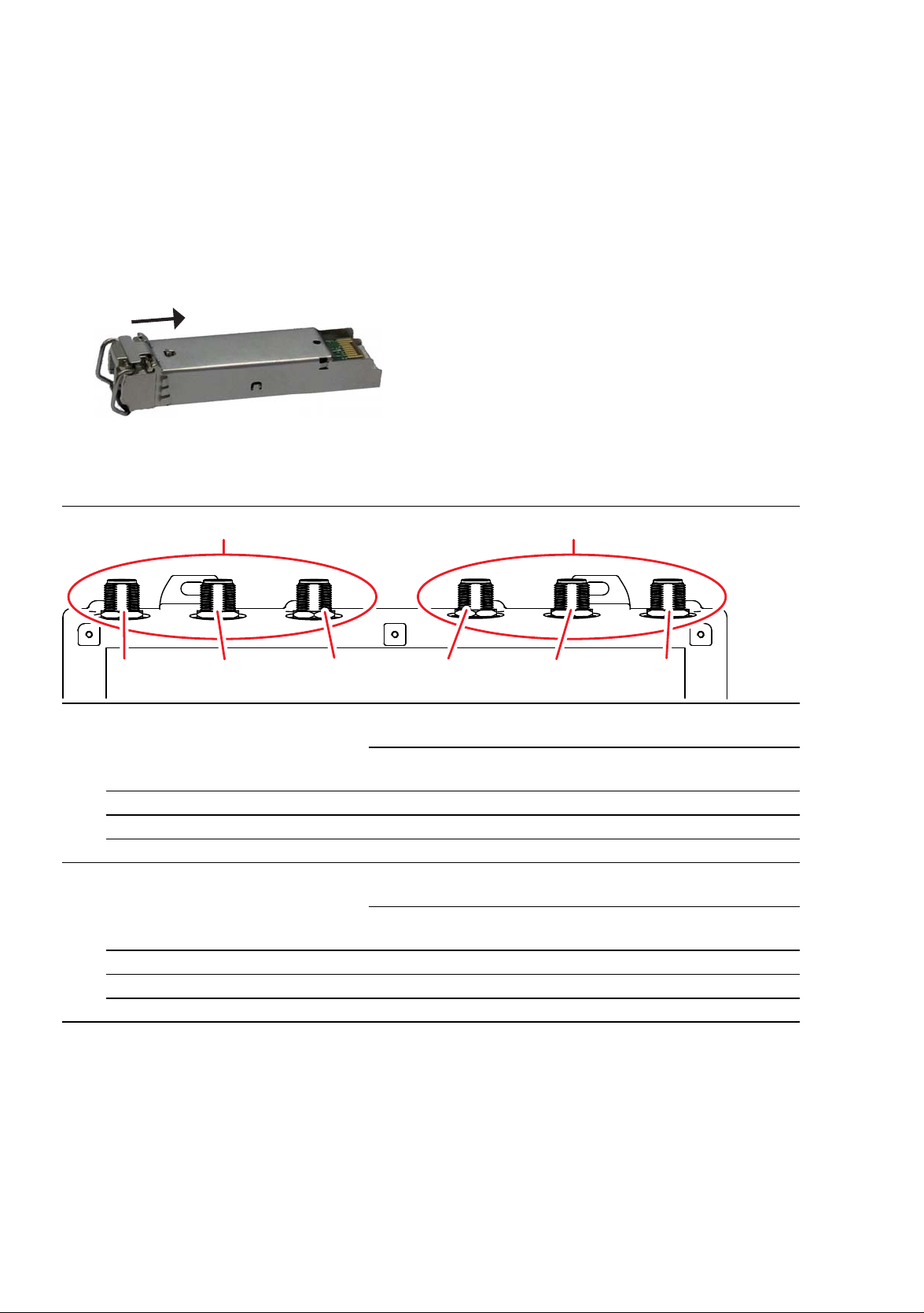
2.3 Installing an SFP transceiver (optional)
1
1b 1c 2a 2b 2c
1a
2
Use only Hirschmann SFP transceivers which are suitable for usage with the
device.
See “Accessories” on page 76.
The SFP mounting tool available as an accessory makes it easier for you to
insert the SFP transceivers.
See “Removing an SFP transceiver (optional)” on page 59.
Remove the protection cap from the SFP transceiver.
Push the SFP transceiver with the lock closed into the slot.
2.4 Installing the antennas
1 alternatively, depending on
device variant
1a Antenna connection 1
1b Antenna connection 2
1c Antenna connection 3
2 alternatively, depending on
device variant
2a Antenna connection 1
2b Antenna connection 2
2c Antenna connection 3
For device variants with 2 WLAN modules:
3 × N socket for WLAN module 1
For device variants with 1 WLAN module:
Not present
For device variants with 2 WLAN modules:
3 × N socket for WLAN module 2
For device variants with 1 WLAN module:
3 × N socket for WLAN module 1
Table 8: Antenna connections
If you connect to 2 BAT-F devices antennas to 2 WLAN modules, ensure that
there is a distance of at least 2 m between the BAT-F devices.
44
Installation BAT-F
Release 17 12/2019
Page 45

If you would like to connect several antennas to a WLAN module, align the
antennas so that the points of the antennas point away form each other in a
star shape.
Install at least one antenna on the WLAN module that you would like to
use.
Insert the terminating resistors available as accessories into the sockets
not being used in order to avoid radio signals from one WLAN module
being received by the other WLAN module.
Relevant for use of BAT-ANT-N-MiMo-18N-IP65 with FCC and approval 2,
characteristic value H. The devices are labeled as follows:
“FCC ID: U99EWLAN2 and IC: 4019A-EWLAN2”
Connect the BAT-ANT-N-MiMo-18N-IP65 to the WLAN module as follows:
Connect the antenna port "Ver" with the WLAN antenna port 1.
Connect the antenna port "+45 °" with the WLAN antenna port 2.
Connect the antenna port "-45 °" with the WLAN antenna port 3.
Connect the BAT-ANT-N-MiMo-18N-IP65 in this way exclusively.
2.5 Connecting the power supply and the signal contact lines
WARNING
ELECTRIC SHOCK
Before connecting the electrical wires, always verify that the requirements
listed are complied with.
See “Requirements for connecting electrical wires” on page 9.
See “Requirements for connecting the supply voltage” on page 9.
Failure to follow this instruction can result in death, serious injury, or
equipment damage.
The supply voltage is electrically isolated from the casing.
You have the option of supplying the supply voltage redundantly, without
load distribution.
Installation BAT-F
Release 17 12/2019
45
Page 46

2.5.1 Supply voltage with the characteristic value C (24 V DC ... 48 V DC)
Perform the following steps for the supply voltage to be connected, or for
device variants with 2 supply voltage connections of this type, for every
supply voltage to be connected.
Type and specification of the supply
voltage
Rated voltage range DC:
24 V DC ... 48 V DC
Voltage range DC incl. maximum
tolerances:
18 V DC ... 60 V DC
Pin assignment on the device
P- Minus terminal of the supply
P+ P-
voltage
N.C. —
N.C. —
N.C.
N.C.
P+ Plus terminal of the supply
voltage
Table 9: Supply voltage with characteristic value C (24 V DC ... 48 V DC): type
and specification of the supply voltage, pin assignment on the device
For every supply voltage to be connected, perform the following steps:
Connect the wires for the supply voltage according to the pin assignment
with a suitable socket.
2.5.2 Supply voltage with the characteristic value K (60 V DC ... 250 V DC / 110 V AC ... 230 V AC, 50 Hz ... 60 Hz)
WARNING
ELECTRIC SHOCK
Install this device only in a switch cabinet or in an operating site with
restricted access, to which maintenance staff have exclusive access.
Failure to follow this instruction can result in death, serious injury, or
equipment damage.
46
Installation BAT-F
Release 17 12/2019
Page 47

Type of the
NL
PE
N.C.
P+P-
N.C.
voltages that
can be
connected
DC voltage Rated voltage range DC:
AC voltage Rated voltage range AC:
Specification of the supply
voltage
60 V DC ... 250 V DC
Voltage range DC incl.
maximum tolerances:
48 V DC ... 320 V DC
110 V AC ... 230 V AC,
50 Hz ... 60 Hz
Voltage range AC incl.
maximum tolerances:
88 V AC ... 265 V AC,
47 Hz ... 63 Hz
Pin assignment on the device
PE Protective conductor
P+ Plus terminal of the
supply voltage
P-P+
P- Minus terminal of the
PE
PE Protective conductor
L Outer conductor
N Neutral conductor
supply voltage
Table 10: Supply voltage with characteristic value K (60 V DC ... 250 V DC /
110 V AC ... 230 V AC, 50 Hz ... 60 Hz): type and specification of the
supply voltage, pin assignment on the device
Connect the wires for the supply voltage and the protective grounding
according to the pin assignment with a suitable socket.
2.5.3 Supply voltage with the characteristic value W (24 V DC)
Type and specification of the
supply voltage
Rated voltage DC:
24 V DC
Voltage range DC incl. maximum
tolerances:
16.8 V DC ... 32 V DC
Table 11: Supply voltage with characteristic value W (24 V DC): type and
specification of the supply voltage, pin assignment on the device
Pin assignment on the device
P- Minus terminal of the supply
voltage
N.C. —
N.C. —
P+ Plus terminal of the supply
voltage
For every supply voltage to be connected, perform the following steps:
Connect the wires for the supply voltage according to the pin assignment
with a suitable socket.
Installation BAT-F
Release 17 12/2019
47
Page 48

2.5.4 Signal contact
1
23
4
Pin Function
1 Signal contact 2
2 Signal contact 2
3 Signal contact 1
4 Signal contact 1
Table 12: Pin assignment of the signal contact, 4-pin, “A”-coded M12 plug
Only device variants featuring supply voltage with characteristic value C
(24 V DC ... 48 V DC), K (60 V DC ... 250 V DC / 110 V AC ... 230 V AC,
50 Hz ... 60 Hz) or W (24 V DC) have a signal contact.
For the signal contacts to be connected, make sure that the following
requirements are met:
The electrical wires are voltage-free.
The connected voltage is limited by a current limitation device or a fuse.
Observe the electrical threshold values for the signal contact.
See “General technical data” on page 60.
Connect the signal contact lines according to the pin assignment with a
suitable socket.
Plug the socket into the M12 plug on the device.
The tightening torque of the locking screw is 5.3 lb-in (0.6 Nm).
2.6 Operating the device
WARNING
ELECTRIC SHOCK
Before connecting the electrical wires, always verify that the requirements
listed are complied with.
See “Requirements for connecting electrical wires” on page 9.
See “Requirements for connecting the supply voltage” on page 9.
Failure to follow this instruction can result in death, serious injury, or
equipment damage.
By connecting the supply voltage via a 7/8" plug or a twisted pair cable
(Power over Ethernet), you start the operation of the device.
48
Installation BAT-F
Release 17 12/2019
Page 49

2.6.1 Connecting the power supply through a 7/8" connector
You find the prescribed tightening torque of the locking screw in General
technical data section on page 60.
Plug the socket into the 7/8" connector on the device.
Enable the supply voltage.
2.6.2 Connecting the power supply through PoE
NOTICE
MATERIAL DAMAGE
In a PoE installation, use only devices that comply with the IEEE 802.3af/at
standard.
Failure to follow this instruction can lead to equipment damage.
Only for device variants featuring supply voltage with the characteristic
value P (Power supply only through PoE) or W (24 V DC):
By connecting the supply voltage via PoE, you start the operation of the
device.
2.7 Connecting data cables
2.7.1 Gigabit combo port
10/100/1000 Mbit/s PoE PD port
Further information:
“10/100/1000 Mbit/s PoE PD port” on page 33
Connect the data cables according to your requirements.
The tightening torque of the locking screw is 5.3 lb-in (0.6 Nm).
1000 Mbit/s F/O port
Further information:
“1000 Mbit/s F/O port” on page 34
Make sure that you connect LH ports exclusively with LH ports, SX ports
exclusively with SX ports, and LX ports exclusively with LX ports.
Connect the data cables according to your requirements.
Installation BAT-F
Release 17 12/2019
49
Page 50

2.7.2 10/100/1000 Mbit/s twisted-pair connection (optional)
Further information:
“10/100/1000 Mbit/s twisted-pair connection (optional)” on page 34
Connect the data cables according to your requirements.
The tightening torque of the locking screw is 5.3 lb-in (0.6 Nm).
50
Installation BAT-F
Release 17 12/2019
Page 51

3 Making basic settings
The IP parameters must be entered when the device is installed for the first
time. The device provides the following options for configuring IP addresses:
Input via the V.24 interface
Entry via the HiDiscovery protocol in the applications HiDiscovery or
Industrial HiVision
Configuration via BOOTP
Configuration via DHCP (Option 82)
AutoConfiguration Adapter
You will find more information in the “User Manual Configuration Guide”.
The manual is available for download on the Internet: https://
www.doc.hirschmann.com
Installation BAT-F
Release 17 12/2019
51
Page 52

4 First login (Password change)
Applies to devices with the following software release and later:
HiLCOS 10.12-RU2
To help prevent undesired access to the device, it is imperative that you
change the default password during initial setup.
Perform the following steps:
Open the Graphical User Interface, the Command Line Interface or
LANconfig the first time you log on to the device.
Log on to the device with the default password “private”.
The device prompts you to type in a new password.
Note: When you log on with LANconfig, the device prompts you to type in
a new password before your first configuration change.
Type in your new password.
Choose a password that contains at least 8 characters which includes
upper-case characters, lower-case characters, numerical digits and
special characters.
Confirm your new password.
For further information see:
https://hirschmann-support.belden.com/en/kb/required-password-changenew-procedure-for-first-time-login
52
Installation BAT-F
Release 17 12/2019
Page 53

5 Obtain compliance for operation in the
European Union
For operation in the European Union, the device must comply with the Radio
Equipment Directive (RED) 2014/53/EU. The RED compliance requires
compliant operation of the device in the 5 GHz band channels. Compliant
operation of the device is achieved by an unchangeable determination of the
country setting.
Make the country setting unchangeable using the Command Line Interface
(CLI), the graphical user interface or the LANconfig software. You can
download the LANconfig software as an ISO image from the Hirschmann
product pages (www.hirschmann.com).
Perform the following work steps:
Command Line Interface (CLI)
To access the possible country settings, execute the following
command:
set Setup/WLAN/Country ?
Note: The country setting “Europe” is valid for all European countries.
Specific country settings such as “France” or “Germany” include
additional country specific channels in comparison to the “Europe”
country setting.
The device ignores specific country settings and uses the country
setting “Europe” until the RED compliance has been obtained.
Select the desired country setting with the following command:
set Setup/WLAN/Country [Country]
Example:
set Setup/WLAN/Country France
Execute the following command:
> REDcompliance
Installation BAT-F
Release 17 12/2019
53
Page 54

Note: To check the country setting and correct it, type no. Then check
the country setting with the following command: ls Setup/WLAN/
Country.
To obtain RED compliance, type yes. This makes the country setting
unchangeable. Subsequently, the device restarts.
Graphical user interface
Open the Configuration > Wireless LAN > General dialog and select
the desired country setting.
Note: The country setting “Europe” is valid for all European countries.
Specific country settings such as “France” or “Germany” include
additional country specific channels in comparison to the “Europe”
country setting.
The device ignores specific country settings and uses the country
setting “Europe” until the RED compliance has been obtained.
To confirm your choice, click the “Send” button.
Open the Extras > RED compliance dialog.
Note: To check the country setting and correct it, open the
Configuration > Wireless LAN > General dialog.
To obtain RED compliance, click the “Confirm RED compliance”
button. This makes the country setting unchangeable. Subsequently,
the device restarts.
LANconfig
In the LANconfig device overview, highlight the row containing the
desired device.
In the menu bar, select Device > Configure.
Open the Configuration > Wireless LAN > General dialog and select
the desired country setting.
Note: The country setting “Europe” is valid for all European countries.
Specific country settings such as “France” or “Germany” include
additional country specific channels in comparison to the “Europe”
country setting.
The device ignores specific country settings and uses the country
setting “Europe” until the RED compliance has been obtained.
54
Installation BAT-F
Release 17 12/2019
Page 55

To confirm your choice, click the “OK” button.
In the LANconfig device overview, highlight the row containing the
desired device.
In the menu bar, select Device > RED compliance.
Note: To check the country setting and correct it, click the “No” button.
Then open the Configuration > Wireless LAN > General dialog.
To obtain RED compliance, click the “Yes” button. This makes the
country setting unchangeable. Subsequently, the device restarts.
Installation BAT-F
Release 17 12/2019
55
Page 56

6 Configuring the transmit power
Note: The operator of a WLAN radio installation must adhere to the
applicable transmission threshold values.
Use the graphical user interface or the LANconfig software. You can
download the LANconfig software as an ISO image from the Hirschmann
product pages (www.hirschmann.com).
In the graphical user interface, proceed as follows:
In the menu tree, open the Configuration > Wireless LAN > General
dialog.
In the “General” tab, specify in the “General” frame the country in which
you install the device, and click the “Send” button.
Note: For devices that are operated in the European Union perform
thework steps described in chapter “Obtain compliance for operation in
the European Union” on page 53.
In the menu tree, open the Configuration > Wireless LAN > General >
Physical WLAN settings - Radio dialog.
In the “General” tab, click in the “Interface” column the physical WLAN
interface to which you connect the antenna.
56
Installation BAT-F
Release 17 12/2019
Page 57

Subtract the cable and installed overvoltage protector attenuation from
the antenna gain. Enter the calculated value in the “Antenna gain” field.
To save the value, click the “Send” button.
Installation BAT-F
Release 17 12/2019
57
Page 58

7 Maintenance and service
When designing this device, Hirschmann largely avoided using high-wear
parts. The parts subject to wear and tear are dimensioned to last longer
than the lifetime of the product when it is operated normally. Operate this
device according to the specifications.
Relays are subject to natural wear. This wear depends on the frequency
of the switching operations. Check the resistance of the closed relay
contacts and the switching function depending on the frequency of the
switching operations.
Hirschmann is continually working on improving and developing their
software. Check regularly whether there is an updated version of the
software that provides you with additional benefits. You find information
and software downloads on the Hirschmann product pages on the
Internet (http://www.hirschmann.com).
Note: You find information on settling complaints on the Internet at http://
www.beldensolutions.com/en/Service/Repairs/index.phtml.
58
Installation BAT-F
Release 17 12/2019
Page 59

8Disassembly
132
8.1 Removing the device
Disconnect the data cables.
Disable the supply voltage.
Disconnect the power supply cables and signal lines.
Remove the antennas.
Disconnect the grounding.
8.2 Removing an SFP transceiver (optional)
To disassemble SFP transceivers, you require the SFP mounting tool
available as an accessory .
See “Accessories” on page 76.
Figure 1: SFP mounting tool
1 – mounting side
2 – barbed hooks
3 – disassembly side
Insert the SFP mounting tool so into the SFP transceiver that the barbed
hooks point to the locking handle of the SFP transceivers.
Gently press the SFP mounting tool in the direction of the lock so that the
barbed hooks link into the strap.
Pull the SFP transceiver out of the slot using the mounting tool.
Close the slot with the protection cap.
Installation BAT-F
Release 17 12/2019
59
Page 60

9 Technical data
9.1 General technical data
Weight Device variants featuring supply voltage with
characteristic value P (Power supply only through
PoE)
Device variants featuring supply voltage with
characteristic value C (24 V DC ... 48 V DC) or K
(60 V DC ... 250 V DC / 110 V AC ... 230 V AC,
50 Hz ... 60 Hz)
Device variants featuring supply voltage with
characteristic value W (24 V DC)
and approvals 1 with the characteristic value I, M
or 9
Device variants featuring supply voltage with
characteristic value W (24 V DC)
and approvals 1 with the characteristic value F or G
Device variants featuring supply voltage with
characteristic value W (24 V DC)
and approvals 1 with characteristic value K
Supply voltage
with the
characteristic
value C
Power supply solely through a 7/8" connector
Rated voltage range DC: 24 V DC ... 48 V DC
Class 2
Voltage range DC incl. maximum
tolerances:
Connection type 4-pin, 7/8" connector
Power loss buffer >10 ms at 20.4 V DC
Overload current protection on
the device
Back-up fuse Nominal rating:
Peak inrush current 14 A
18 V DC ... 60 V DC
Tightening
torque of the
locking screw
Non-replaceable fuse
Characteristic:
approx. 98.56 oz
(2800 g)
approx. 114.64 oz
(3250 g)
approx. 105.82 oz
(3000 g)
approx. 145.33 oz
(4120 g)
approx. 109.35 oz
(3100 g)
22 lb-in (2.5 Nm)
Max. 6.3 A
slow blow
60
Installation BAT-F
Release 17 12/2019
Page 61

Supply voltage
with the
characteristic
value K
Supply voltage
with the
characteristic
value P
Supply voltage
with the
characteristic
value W
Climatic
conditions during
operation
Power supply solely through a 7/8" connector
Rated voltage range AC: 110 V AC ... 230 V AC, 50 Hz ... 60 Hz
Voltage range including
88 V AC ... 265 V AC, 47 Hz ... 63 Hz
maximum tolerances
Rated voltage range 60 V DC ... 250 V DC
Voltage range incl. maximum
48 V DC ... 320 V DC
tolerances
Connection type 3-pin, 7/8" connector
Tightening
22 lb-in (2.5 Nm)
torque of the
locking screw
Power loss buffer > 10 ms at 98 V AC
Overload current protection on
Non-replaceable fuse
the device
Back-up fuse for each voltage
input
Nominal rating:
Characteristic:
2.5 A
slow blow
Peak inrush current 14 A
Power supply solely through PoE
Power supply through a 7/8" connector
Rated voltage 24 V DC
Class 2
Voltage range incl. maximum
16.8 V DC ... 32 V DC
tolerances
Connection type 4-pin, 7/8" connector
Tightening
22 lb-in (2.5 Nm)
torque of the
locking screw
Power loss buffer >10 ms at 20.4 V DC
Overload current protection on
Non-replaceable fuse
the device
Back-up fuse Nominal rating:
Characteristic:
Max. 6.3 A
slow blow
Peak inrush current 14 A
Ambient air temperature
a
Devices with operating temperature
characteristic value S (Standard):
+32 °F ... +140 °F (0 °C ... +60 °C)
Devices with operating temperature
characteristic value E and T (extended):
-40 °F ... +158 °F (-40 °C ... +70 °C)
b
Devices with operating temperature
characteristic value K (Extended with
Conformal Coating, approvals 1 with the
characteristic value K):
-40 °F ... +131 °F (-40 °C ... +55 °C)
Humidity 10 % ... 95 %
Air pressure up to 6562 ft (2000 m; 795 hPa), higher
altitudes upon request
max. 1060 hPa (-1312 ft; -400 m)
Installation BAT-F
Release 17 12/2019
61
Page 62

Climatic
73
184
31 1
207
2
19
mm
in
12.24
7.24
8.15
8.62
2.87
conditions during
storage
Minimum clearance around the
device
Ambient air temperature
a
Top and bottom device side: 3.94 in
(10 cm)
Left and right device side: 0.79 in (2 cm)
-40 °F ... +185 °F (-40 °C ... +85 °C)
Humidity 10 % ... 95 %
Air pressure min. 700 hPa (+9842 ft; +3000 m)
max. 1060 hPa (-1312 ft; -400 m)
Signal contact
“FAULT”
Switching current max. 1 A, SELV
Switching voltage Supply voltage with characteristic value C
(24 V DC ... 48 V DC) and K (60 V DC ...
250 V DC / 110 V AC ... 230 V AC,
50 Hz ... 60 Hz):
max. 60 V DC or max. 30 V AC, SELV
Supply voltage with the characteristic
value W:
max. 30 V DC, SELV
Pollution degree 2
Protection
classes
Laser protection Class 1 in compliance with IEC 60825-1
Degree of protection IP65/67
a. Temperature of the ambient air at a distance of 2 in (5 cm) from the device
b. Use SFP transceivers with the “EEC” extension only, otherwise the standard temperature
range applies.
9.2 Dimension drawings
Figure 2: Dimensions of device variants and distance between suspensions.
Installation BAT-F
62
Release 17 12/2019
Page 63

311
322,46
74,37
mm
inch
12.24
2.93
12.70
Figure 3: Dimensions of the device variants with impact protection.
Installation BAT-F
Release 17 12/2019
63
Page 64

Figure 4: Distances of the suspension with impact protection.
184
207 38,69
mm
inch
7.24
1.52
8.15
64
Installation BAT-F
Release 17 12/2019
Page 65

9.3 Radio technology
Antenna connection For each WLAN module: 3 × N socket
Range Depending on the antenna used, frequency range and data rate
Encryption
Frequency range
Modulation technology
Radio topology WLAN Access-Point, Bridge-, Router-, Point-to-Point-, Client-, Client-
IEEE 802.11i/WPA2 with passphrase or IEEE 802.1x and
hardware-accelerated AES
Closed Network
WEP 64
WEP 128
WEP 152
User authentication
802.1x/EAP
LEPS
WPA1/TKIP
For more information, see the HiLCOS data sheet.
Support of 2.4 GHz and 5 GHz: 2412 MHz to 2472 MHz and
5180 MHz to 5825 MHz
OFDM: BPSK, QPSK, 16-QAM, 64-QAM
DSSS/CCK, DSSS/DBPSK, DSSS/DQPSK
Bridge-Mode
a
b
c
d
a. With encryptions of the type TKIP and WEP, the device falls back on IEEE 802.11b/g or
IEEE 802.11a.
b. With encryptions of the type TKIP and WEP, the device falls back on IEEE 802.11b/g or
IEEE 802.11a.
c. With encryptions of the type TKIP and WEP, the device falls back on IEEE 802.11b/g or
IEEE 802.11a.
d. With encryptions of the type TKIP and WEP, the device falls back on IEEE 802.11b/g or
IEEE 802.11a.
9.4 Roaming
IEEE 802.11F (Inter-Access Point Protocol)
IEEE 802.11r (Fast Roaming)
PMK caching
Pre authentification
OKC (Opportunistic key caching)
Installation BAT-F
Release 17 12/2019
65
Page 66

9.5 Receiving sensitivity, transmit power, and
data rate of the WLAN module version
EWLAN1 (Approvals 2, characteristic
value M or 9)
The values shown in the following tables are the maximum values of the
WLAN module version EWLAN1. The values are in no case to be perceived
as a guaranteed property of the overall product. For some country profiles,
the module reduces data rate and transmit power automatically. The reason
for this are national standards.
9.5.1 IEEE 802.11b
IEEE 802.11b
Frequency range 2.412 GHz to 2.472 GHz
Data rate Typical transmit power Typical receiving sensitivity
1Mbit/s 19dBm 94 dBm
11 Mbit/s 19 dBm 94 dBm
Table 13: IEEE 802.11b, Frequency range 2.412 GHz to 2.472 GHz
9.5.2 IEEE 802.11g
IEEE 802.11g
Frequency range 2.412 GHz to 2.472 GHz
Data rate Typical transmit power Typical receiving sensitivity
6Mbit/s 22dBm 94 dBm
9Mbit/s 22dBm 94 dBm
12 Mbit/s 22 dBm 90 dBm
18 Mbit/s 22 dBm 89 dBm
24 Mbit/s 22 dBm 85 dBm
36 Mbit/s 21 dBm 82 dBm
48 Mbit/s 20 dBm 78 dBm
54 Mbit/s 19 dBm 77 dBm
Table 14: IEEE 802.11g, Frequency range 2.412 GHz to 2.472 GHz
9.5.3 IEEE 802.11a
IEEE 802.11a
Bandwidth 5.180 GHz to 5.825 GHz
Data rate Typical transmit power Typical receiving sensitivity
6Mbit/s 16dBm 93 dBm
9Mbit/s 16dBm 93 dBm
Table 15: IEEE 802.11a, Frequency range 5.180 GHz to 5.825 GHz
Installation BAT-F
66
Release 17 12/2019
Page 67

IEEE 802.11a
Bandwidth 5.180 GHz to 5.825 GHz
Data rate Typical transmit power Typical receiving sensitivity
12 Mbit/s 16 dBm 93 dBm
18 Mbit/s 16 dBm 91 dBm
24 Mbit/s 16 dBm 88 dBm
36 Mbit/s 15 dBm 84 dBm
48 Mbit/s 13 dBm 80 dBm
54 Mbit/s 12 dBm 79 dBm
Table 15: IEEE 802.11a, Frequency range 5.180 GHz to 5.825 GHz
9.5.4 IEEE 802.11n
IEEE 802.11n
Frequency range 2.412 GHz to 2.472 GHz
Coding Typical transmit power Typical receiving sensitivity
MCS 0 18 dBm 87 dBm
MCS 1 18 dBm 90 dBm
MCS 2 18 dBm 86 dBm
MCS 3 18 dBm 82 dBm
MCS 4 18 dBm 79 dBm
MCS 5 16 dBm 75 dBm
MCS 6 16 dBm 73 dBm
MCS 7 15 dBm 72 dBm
MCS 8 22 dBm 87 dBm
MCS 9 21 dBm 90 dBm
MCS 10 22 dBm 86 dBm
MCS 11 21 dBm 82 dBm
MCS 12 16 dBm 79 dBm
MCS 13 16 dBm 75 dBm
MCS 14 15 dBm 73 dBm
MCS 15 15 dBm 72 dBm
MCS 16 23 dBm 87 dBm
MCS 17 23 dBm 90 dBm
MCS 18 23 dBm 86 dBm
MCS 19 23 dBm 82 dBm
Table 16: IEEE 802.11n, Frequency range 2.412 GHz to 2.472 GHz
Installation BAT-F
Release 17 12/2019
67
Page 68

IEEE 802.11n
Frequency range 2.412 GHz to 2.472 GHz
Coding Typical transmit power Typical receiving sensitivity
MCS 20 16 dBm 79 dBm
MCS 21 17 dBm 75 dBm
MCS 22 17 dBm 73 dBm
MCS 23 16 dBm 72 dBm
Table 16: IEEE 802.11n, Frequency range 2.412 GHz to 2.472 GHz
IEEE 802.11n
Frequency range 5.180 GHz to 5.825 GHz
Coding Typical transmit power Typical receiving sensitivity
MCS 0 17 dBm 92 dBm
MCS 1 17 dBm 91 dBm
MCS 2 17 dBm 89 dBm
MCS 3 17 dBm 84 dBm
MCS 4 17 dBm 81 dBm
MCS 5 15 dBm 77 dBm
MCS 6 14 dBm 75 dBm
MCS 7 14 dBm 73 dBm
MCS 8 20 dBm 92 dBm
MCS 9 20 dBm 91 dBm
MCS 10 19 dBm 89 dBm
MCS 11 20 dBm 84 dBm
MCS 12 18 dBm 81 dBm
MCS 13 15 dBm 77 dBm
MCS 14 15 dBm 75 dBm
MCS 15 14 dBm 73 dBm
MCS 16 21 dBm 92 dBm
MCS 17 21 dBm 91 dBm
MCS 18 21 dBm 89 dBm
MCS 19 21 dBm 84 dBm
MCS 20 16 dBm 81 dBm
MCS 21 15 dBm 77 dBm
MCS 22 14 dBm 75 dBm
MCS 23 14 dBm 73 dBm
Table 17: IEEE 802.11n, Frequency range 5.180 GHz to 5.825 GHz
68
Installation BAT-F
Release 17 12/2019
Page 69

9.6 Receiving sensitivity, transmit power, and data rate of the WLAN module version EWLAN2 for high-gain antennas (Approvals 2, characteristic value H)
The values shown in the following tables are the maximum values of the
WLAN module version EWLAN2 for high-gain antennas. The values are in
no case to be perceived as a guaranteed property of the overall product. For
some country profiles, the module reduces data rate and transmit power
automatically. The reason for this are national standards.
9.6.1 IEEE 802.11b
IEEE 802.11b
Frequency range 2.412 GHz to 2.472 GHz
Data rate Typical transmit power Typical receiving sensitivity
1 Mbit/s 19 dBm 94 dBm
11 Mbit/s 19 dBm 94 dBm
Table 18: IEEE 802.11b, Frequency range 2.412 GHz to 2.472 GHz
9.6.2 IEEE 802.11g
IEEE 802.11g
Frequency range 2.412 GHz to 2.472 GHz
Data rate Typical transmit power Typical receiving sensitivity
6 Mbit/s 22 dBm 94 dBm
9 Mbit/s 22 dBm 94 dBm
12 Mbit/s 22 dBm 90 dBm
18 Mbit/s 22 dBm 89 dBm
24 Mbit/s 22 dBm 85 dBm
36 Mbit/s 21 dBm 82 dBm
48 Mbit/s 20 dBm 78 dBm
54 Mbit/s 19 dBm 77 dBm
Table 19: IEEE 802.11g, Frequency range 2.412 GHz to 2.472 GHz
9.6.3 IEEE 802.11a
IEEE 802.11a
Frequency range 5.180 GHz to 5.825 GHz
Data rate Typical transmit power Typical receiving sensitivity
6 Mbit/s 10 dBm 93 dBm
9 Mbit/s 10 dBm 93 dBm
Table 20: IEEE 802.11a, Frequency range 5.180 GHz to 5.825 GHz
Installation BAT-F
Release 17 12/2019
69
Page 70

IEEE 802.11a
Frequency range 5.180 GHz to 5.825 GHz
Data rate Typical transmit power Typical receiving sensitivity
12 Mbit/s 10 dBm 93 dBm
18 Mbit/s 10 dBm 91 dBm
24 Mbit/s 10 dBm 88 dBm
36 Mbit/s 9 dBm 84 dBm
48 Mbit/s 7 dBm 80 dBm
54 Mbit/s 6 dBm 79 dBm
Table 20: IEEE 802.11a, Frequency range 5.180 GHz to 5.825 GHz
9.6.4 IEEE 802.11n
IEEE 802.11n
Frequency range 2.412 GHz to 2.472 GHz
Coding Typical transmit power Typical receiving sensitivity
MCS 0 18 dBm 87 dBm
MCS 1 18 dBm 90 dBm
MCS 2 18 dBm 86 dBm
MCS 3 18 dBm 82 dBm
MCS 4 18 dBm 79 dBm
MCS 5 16 dBm 75 dBm
MCS 6 16 dBm 73 dBm
MCS 7 15 dBm 72 dBm
MCS 8 22 dBm 87 dBm
MCS 9 21 dBm 90 dBm
MCS 10 22 dBm 86 dBm
MCS 11 21 dBm 82 dBm
MCS 12 16 dBm 79 dBm
MCS 13 16 dBm 75 dBm
MCS 14 15 dBm 73 dBm
MCS 15 15 dBm 72 dBm
MCS 16 23 dBm 87 dBm
MCS 17 23 dBm 90 dBm
MCS 18 23 dBm 86 dBm
MCS 19 23 dBm 82 dBm
Table 21: IEEE 802.11n, Frequency range 2.412 GHz to 2.472 GHz
70
Installation BAT-F
Release 17 12/2019
Page 71

IEEE 802.11n
Frequency range 2.412 GHz to 2.472 GHz
Coding Typical transmit power Typical receiving sensitivity
MCS 20 16 dBm 79 dBm
MCS 21 17 dBm 75 dBm
MCS 22 17 dBm 73 dBm
MCS 23 16 dBm 72 dBm
Table 21: IEEE 802.11n, Frequency range 2.412 GHz to 2.472 GHz
IEEE 802.11n
Frequency range 5.180 GHz to 5.825 GHz
Coding Typical transmit power Typical receiving sensitivity
MCS 0 11 dBm 92 dBm
MCS 1 11 dBm 91 dBm
MCS 2 11 dBm 89 dBm
MCS 3 11 dBm 84 dBm
MCS 4 11 dBm 81 dBm
MCS 5 9 dBm 77 dBm
MCS 6 8 dBm 75 dBm
MCS 7 8 dBm 73 dBm
MCS 8 7 dBm 92 dBm
MCS 9 7 dBm 91 dBm
MCS 10 6 dBm 89 dBm
MCS 11 7 dBm 84 dBm
MCS 12 5 dBm 81 dBm
MCS 13 2 dBm 77 dBm
MCS 14 2 dBm 75 dBm
MCS 15 1 dBm 73 dBm
MCS 16 8 dBm 92 dBm
MCS 17 8 dBm 91 dBm
MCS 18 8 dBm 89 dBm
MCS 19 8 dBm 84 dBm
MCS 20 3 dBm 81 dBm
MCS 21 2 dBm 77 dBm
Table 22: IEEE 802.11n, Frequency range 5.180 GHz to 5.825 GHz
Installation BAT-F
Release 17 12/2019
71
Page 72

IEEE 802.11n
Frequency range 5.180 GHz to 5.825 GHz
Coding Typical transmit power Typical receiving sensitivity
MCS 22 1 dBm 75 dBm
MCS 23 1 dBm 73 dBm
Table 22: IEEE 802.11n, Frequency range 5.180 GHz to 5.825 GHz
9.7 EMC and immunity
EMC interference
immunity
EN 61000-4-2 Electrostatic discharge
Contact discharge, test level 4 ±8 kV
Air discharge, test level 4 ±15 kV
EN 61000-4-3 Electromagnetic field
80 MHz ... 1000 MHz 20 V/m
1400 MHz ... 2700 MHz 10 V/m
EN 61000-4-4 Fast transients (burst), test level 4
DC power line ±4 kV
AC Power Line ±4 kV
Data line ±4 kV
EN 61000-4-5 Voltage surges
DC power line ±2 kV line/ground; ±1 kV line/line
AC Power Line ±4 kV line/ground; ±2 kV line/line
Data line, shielded ±4 kV line/ground
Data line, unshielded ±2 kV line/ground
Data line, unshielded ±1 kV line/line
EN 61000-4-6 Conducted interference voltages, test level 3
150 kHz ... 80 MHz 10 V
EN 61000-4-9 Pulse magnetic fields 300 A/m
EMC interference
emission
EN 55032 Class B
FCC 47 CFR Part 15 Class A
Immunity
Vibration IEC 60068-2-6 Test FC test level according to IEC 61131-2
Shock IEC 60068-2-27 Test Ea test level in accordance with IEC 61131-2,
EN 50155
Installation BAT-F
72
Release 17 12/2019
Page 73

9.8 Network range
Note: The line lengths specified for the transceivers apply for the respective
fiber data (fiber attenuation and Bandwidth Length Product (BLP)/
Dispersion).
Product
code
M-SFP-...
-SX/LC... MM 850 nm 50/125 µm 0 dB ...
-SX/LC... MM 850 nm 62.5/125 µm 0 dB ...
-LX/LC... MM 1310 nm
-LX/LC... MM 1310 nm
-LX/LC... SM 1310 nm 9/125 µm 0 dB ...
-LH/LC... LH 1550 nm 9/125 µm 5 dB ...
-LH+/LC LH 1550 nm 9/125 µm 15 dB ...
-LH+/LC LH 1550 nm 9/125 µm 15 dB ...
Wave
length
Fiber System
attenuation
7.5 dB
7.5 dB
c
50/125 µm 0 dB ...
10.5 dB
d
62.5/125 µm 0 dB ...
10.5 dB
10.5 dB
22 dB
30 dB
30 dB
Example
for F/O
cable
length
0 mi ...
0.34 mi
(0 km ...
0.55 km)
0 mi ...
0.17 mi
(0 km ...
0.275 km)
0 mi ...
0.34 mi
(0 km ...
0.55 km)
0 mi ...
0.34 mi
(0 km ...
0.55 km)
0 mi ...
12.43 mi
(0 km ...
20 km)
14.29 mi ...
49.71 mi
(23 km ...
80 km)
44.12 mi ...
67.11 mi
(71 km ...
108 km)
44.12 mi ...
79.54 mi
(71 km ...
128 km)
a
e
Fiber
attenuation
3.0 dB/km 400 MHz×km
3.2 dB/km 200 MHz×km
1.0 dB/km 800 MHz×km
1.0 dB/km 500 MHz×km
0.4 dB/km 3.5 ps/
0.25 dB/km 19 ps/(nm×km)
0.25 dB/km 19 ps/(nm×km)
0.21 dB/km
(typically)
BLPb/
Dispersion
(nm×km)
19 ps/(nm×km)
Table 23: F/O port 1000BASE-FX (SFP fiber optic Gigabit Ethernet Transceiver)
a. Including 3 dB system reserve when compliance with the fiber data is observed.
b. Using the bandwidth-length product is inappropriate for expansion calculations.
c. With F/O adapter compliant with IEEE 802.3-2002 Clause 38 (single-mode fiber offset-launch
mode conditioning patch cord).
d. With F/O adapter compliant with IEEE 802.3-2002 Clause 38 (single-mode fiber offset-launch
mode conditioning patch cord).
e. Including 2.5 dB system reserve when compliance with the fiber data is observed.
MM = Multimode, SM = Singlemode, LH = Singlemode Longhaul
Installation BAT-F
Release 17 12/2019
73
Page 74

10/100/1000 Mbit/s twisted pair port
Length of a twisted pair segment max. 328 ft (100 m) (for Cat5e cable)
Table 24: Network range: 10/100/1000 Mbit/s twisted pair port
9.9 Power consumption/power output
Conditions Maximum
power consumption
When equipped with 1 WLAN module 12.95 W 44.19 Btu (IT)/h
When equipped with 2 WLAN
modules
17.5 W 59.71 Btu (IT)/h
Power output
74
Installation BAT-F
Release 17 12/2019
Page 75

10 Scope of delivery, order numbers and
accessories
Scope of delivery
Number Article
1 × Device
1 × Safety and general information sheet
1 × EU Declaration of Conformity
1 × Terminal cable: M12 plug, 8-pin on DB9 socket
3 × per WLAN module 3-dBi dipole dual-band antennas for initial operation
2 × Power supply plug, for cable diameters of 0.24 in to 0.32 in (6 mm to
8 mm; model dependent on the characteristic value of the socket)
You find power supply plugs with a larger thread here:
“Accessories” on page 76
1× or2×
(depending on the
device variant)
2×
premounted
3×
premounted
2×
premounted
1 × per WLAN module
premounted
1×
premounted
1×
premounted
3× or4×
premounted
(depending on the
device variant)
“X”-coded M12 plug
50 terminating resistor for sealing unused antenna connections
(exclusively for device variants with 1 wireless module)
50 terminating resistor for sealing unused antenna connections
(exclusively for device variants with 2 wireless modules)
Protection cap (7/8", plastic) for supply voltage connection
Protection cap (plastic) for N socket
Protection cap (7/8", plastic) for SFP slot
Protection screw (M12, metal) for signal contact
Protection screw (M12, metal) for interfaces
Figure 5: Scope of delivery for device variants featuring Configuration with the
characteristic value Z
Installation BAT-F
Release 17 12/2019
75
Page 76

Number Article
1× Device
1 × Safety and general information sheet
1 × EU Declaration of Conformity
1 × Power supply plug, for cable diameters of 0.24 in to 0.32 in (6 mm to
8 mm; model dependent on the characteristic value of the socket)
You find power supply plugs with a larger thread here:
“Accessories” on page 76
3×per WLAN module
premounted
1×
premounted
1×
premounted
1×
premounted
1×
premounted
3× or4×
premounted
(depending on the
device variant)
Protection cap (plastic) for N socket
Protection cap (7/8", plastic) for SFP slot
Protection cap (7/8", plastic) for supply voltage connection
Protection cap (7/8", plastic) for supply voltage connection
Protection screw (M12, plastic) for signal contact
Protection screw (M12, plastic) for interfaces
Figure 6: Scope of delivery for device variants featuring Configuration with the
characteristic value 9
Accessories
Note that products recommended as accessories may have different
characteristics to those of the device, which may limit the application
range of the overall system. For example, if you add an accessory with
IP20 to a device with IP65, the degree of protection of the overall system
is reduced to IP20.
To sustain the IP65/67 suitability for your device, use the accessories with
IP65/67 properties exclusively.
The following accessory parts are not suitable for use within IP65/67
areas:
RJ45 adapters
Terminal cabel
For reliable receive power and transmission power, you require antennas
that pertain to your application case.
The "Antenna Guide" document provides an overview of the antennas
that can be used as well as the suitable antenna accessories.
The manual is available for download on the Internet: https://
www.doc.hirschmann.com
Gigabit Ethernet SFP transceiver Order number
M-SFP-SX/LC 943 014-001
M-SFP-SX/LC-EEC 943 896-001
Installation BAT-F
76
Release 17 12/2019
Page 77

Gigabit Ethernet SFP transceiver Order number
M-SFP-LX/LC 943 015-001
M-SFP-LX/LC-EEC 943 897-001
M-SFP-LH/LC 943 042-001
M-SFP-LH/LC-EEC 943 898-001
M-SFP-LH+/LC 943 049-001
Other accessories Order number
0986 EMC 600, field-attachable M12 plug for Gigabit Ethernet data
cables
0986 EMC 102, field-attachable M12 plug for Fast Ethernet data
cables
50 terminating resistors for sealing unused antenna connections, N
(10 pieces)
7/8 plug for supply voltage with characteristic value K (60 V DC ...
250 V DC / 110 V AC ... 230 V AC, 50 Hz ... 60 Hz), for cable
diameters 0.24 in ... 0.32 in (6 mm ... 8 mm)
7/8 plug for supply voltage with characteristic value K (60 V DC ...
250 V DC / 110 V AC ... 230 V AC, 50 Hz ... 60 Hz), for cable
diameters 0.32 in to 0.39 in (8 mm bis 10 mm)
7/8 plug for supply voltage with characteristic value W (24 V DC)
and C (24 V DC ... 48 V DC), for cable diameters 0.24 in ... 0.32 in
(6 mm ... 8 mm)
7/8 plug for supply voltage with characteristic value W (24 V DC)
and C (24 V DC ... 48 V DC), for cable diameters 0.32 in to 0.39 in
(8 mm bis 10 mm)
Antenna cable BAT-CLB-2 N m-f 943 903-514
AutoConfiguration Adapter ACA21-M12 (EEC) 943 913-003
AutoConfiguration Adapter ACA22-M12 (EEC) 942 125-001
BAT-ANT-N-3AGN-IP67 (10 pcs.) 942 110-001
BAT Protector 943 903-373
EM12S, field-attachable M12 plug for Fast Ethernet data cables 934 445-001
Pole mounting set for OpenBAT device 942 116-001
Network management software Industrial HiVision 943 156-xxx
PoE power supply unit PC150/36V/48V-IP67, supply voltage
16.8 V DC to 64 V DC
PoE power supply unit PC150/72 V/48V-IP67, supply voltage
50.4 V DC to 154 V DC
SFP mounting tool for IP67 socket 942 079-001
Plug casing for IP67 V1 plug acc. to IEC 61076-3-106 (variant 1) Available at BTR
Terminal cable: M12 plug, 8-pin on DB9 socket 942 087-001
Protection screw for M12 socket, metal, IP65/67 (25 pieces) 942 057-001
Protection screw for M12 plug, metal, IP65/67 (10 pieces) 942 115-001
Protection cap for 7/8“ plug, metal, IP67 (10 pieces) 942 111-001
Available at ICOS
934 637-032
Available at
Lumberg Automation
71327
942 118-001
942 086-003
Available at
Lumberg Automation:
11206
942 086-004
Available at
Lumberg Automation:
11216
943 968-001
943 968-101
NETCOM GmbH
Installation BAT-F
Release 17 12/2019
77
Page 78

11 Underlying technical standards
Name
ATEX (2014/34/EU) ATEX – Intended use of equipment and protection systems in
potentially explosive areas.
CSA 22.2 No. 60950-1 Information Technology Equipment – Safety – Part 1: General
Requirements
ECE No. 10 E type approval for use in vehicles
EN 300 328 Electromagnetic compatibility and radio spectrum matters (ERM)
- bandwidth transfer systems - data transmission equipment
operating in 2.4 GHz ISM band and using spread spectrum
modulation technology
EN 301 489-1 Electromagnetic compatibility for radio equipment and services
EN 301 489-17 Electromagnetic compatibility (EMC) for radio equipment and
services - specific conditions for 2.4 GHz broadband transmission
systems and 5 GHz high-performance RLAN equipment
EN 302 502 Broadband radio access networks (BRAN) – permanently
installed broadband data transmission systems with 5.8 GHz band
EN 301 893 Broadband radio access networks (BRAN) – 5 GHz high
performance Remote Local Area Network (RLAN)
EN 45545-1 Railway applications - Fire protection on railway vehicles - Part 1:
General
EN 45545-2 Railway applications - Fire protection on railway vehicles - Part 2:
Requirements for fire behavior of materials and components.
EN 50155 Railway applications – Electronic equipment used on rolling stock
EN 55032 Electromagnetic compatibility of multimedia equipment –
Emission Requirements
EN 60529 Degrees of protection provided by housing – IP-Code
EN 60950-1 Information technology equipment – Safety – Part 1: General
requirements
EN 60950-22 Installations of IT equipment – Security – Part 22: Outdoor
equipments
EN 61000-6-2 Electromagnetic compatibility (EMC) – Part 6-2: Generic
standards – Immunity for industrial environments
EN 61131-2 Programmable controllers – Part 2: Equipment requirements and
tests
FCC 47 CFR Part 15 Code of Federal Regulations
FM3600 Approval Standard for Electrical Equipment for Use in Hazardous
(Classified) Locations - General Requirements
FM3611 Approval Standard for Nonincendive Electrical Equipment for Use
in Class I and Class II, Division 2, and Class III, Divisions 1 and 2,
Hazardous (Classified) Locations
IEEE 802.1D MAC Bridges (switching function)
IEEE 802.1Q Virtual LANs (VLANs, MRP, Spanning Tree)
IEEE 802.1w Rapid Reconfiguration
IEEE 802.11a/b/g/h/n WLAN
IEEE 802.3 Ethernet
IEEE 802.3af Power over Ethernet
UL 60950-1 Information technology equipment – Safety – Part 1: General
requirements
78
Installation BAT-F
Release 17 12/2019
Page 79

Name
IEC/EN 61850-3 Communication networks and systems for power utility
automation - Part 3: General requirements.
The device has an approval based on a specific standard exclusively if the
approval indicator appears on the device casing.
The device generally fulfills the technical standards named in their current
versions.
Installation BAT-F
Release 17 12/2019
79
Page 80

A Further support
Technical questions
For technical questions, please contact any Hirschmann dealer in your area
or Hirschmann directly.
You find the addresses of our partners on the Internet at http://
www.hirschmann.com.
A list of local telephone numbers and email addresses for technical support
directly from Hirschmann is available at https://
hirschmann-support.belden.com.
This site also includes a free of charge knowledge base and a software
download section.
Hirschmann Competence Center
The Hirschmann Competence Center is ahead of its competitors on three
counts with its complete range of innovative services:
Consulting incorporates comprehensive technical advice, from system
evaluation through network planning to project planning.
Training offers you an introduction to the basics, product briefing and user
training with certification.
You find the training courses on technology and products currently
available at http://www.hicomcenter.com.
Support ranges from the first installation through the standby service to
maintenance concepts.
With the Hirschmann Competence Center, you decided against making any
compromises. Our client-customized package leaves you free to choose the
service components you want to use.
Internet:
http://www.hicomcenter.com
80
Installation BAT-F
Release 17 12/2019
Page 81

Installation BAT-F
Release 17 12/2019
81
Page 82

 Loading...