

Page 1

BELARUS
510/512
510-0000010 РЭ
OPERATING MANUAL
2009
Page 2

This Operating Manual is compiled by Engineer of Minsk Tractor Works Leading
Specialized Design Office I.N. Korobeynik in collaboration with top-level specialists of
the Leading Specialized Design Office of Republican Unitary Enterprise Minsk Tractor
Works
Editor-in-Chief — Director, Scientific and Technical Center
Chief Designer I.N. Uss
Supervisor for the Issue — Head of Design Office, O. N. Natalevich
Belarus-510/512 tractors Operating manual
This Operation and Service Manual contains a brief description and specifications of
Belarus 510/512 tractors manufactured at the Minsk Tractor Works. Basic rules of
machine operation are presented, as well as information on adjustments and technical
servicing of tractor units and assemblies, are given.
This Operating Manual is intended for operators (tractor drivers) operating the Belarus
tractors.
In view of the RUE MTW policy of constant improvement of its products, changes in the
design of certain assemblies and components of the Belarus tractor may be introduced
without notice, that are not represented in this edition.
Some specifications and illustrations found in this Manual may differ from those actually
found on your tractor. The dimensions and weights are approximate (for information
purposes only). For more detailed information, please contact your local Belarus dealer.
General note: References to the “left-hand” or “right-hand” terms in the text of this
Manual are given from the point of view of an observer viewing the moving forward
tractor from behind.
© Minsk Tractor Works Republican Unitary Enterprise, 2009
All rights reserved. No part of this book may be reproduced or copied in any form
whatsoever without written permission of Minsk Tractor Works RUE.
Page 3

TO OPERATOR’S ATTENTION!
1. Before you start operating the tractor, carefully read this Manual and strictly follow
all instructions herein.
2. Use the climatic diesel fuel according to the Manual. Reduce the motor oil
changeover intervals by half, if the sulfur content in the fuel is below 1%.
3. Do not operate the diesel engine at the idle speed more than 15 minutes.
4. Remember that the engine can be only started when the GB lever is in the extreme
left position (in the position of engaging the I or II gear range).
5. Use the synchronous drive of the rear PTO only when the tractor unit speed does
not exceed 8 km/h. Otherwise, severe damages in the tractor power train are
possible.
6. Operate the tractor on the direct gear only with the high gear range engaged (range
II).
7. The tractor cab is equipped with a single seat, only operator is allowed to be in it.
8. When the tractor is shipped from the manufacturer factory, some parts of the tractor
are put into the SPTA box, tool box or cab. Install them onto the tractor on your own.
9. When commissioning new batteries, remove the sealing film from the vent holes or
cut off the bosses on the plastic caps.
10. Do not operate the tractor when the clutch is not totally disengaged or is engaged.
11. When starting movement, make sure that the hand-operated reserve parking brake
is disengaged.
12. When using the tractor without driveshafts, shift the FDA lever to the position
“forced”.
13. Do not work on the tractor in closed rooms without adequate ventilation (air
exchange). Exhaust gases can kill you!
14. Towing the tractor with front wheels lifted is strictly forbidden. Failure to observe this
rule may result in a FDA drive failure and emergency situation.
15. Never lift the front part of the tractor by the towing shackle. Use the shackle for
towing only.
16. The manufacturer continually improves the tractor, due to which there could be
some modifications of the design of some components and their operating rules,
which are not reflected in this Manual.
Page 4

Introduction Belarus-510/512 Operating manual
INTRODUCTION
The BELARUS 510/512 wheeled universal tilling tractors belong to the drawbar
category 1.4 and are designed to perform a wide range of agricultural works: from soil
preparation for sowing to harvesting and transporting operations; they can be used in
forestry, municipal servicing, construction and industry.
This Manual contains a description of the design features, brief technical data and
recommendations for operation and maintenance of the BELARUS 510/512 tractors:
BELARUS-510/512 (4×2) and (4×4) with a Д244 diesel engine (41.9 kW at 1700
rpm), a 9F/2R manual gearbox.
Re-equipment or modifications to the tractor design without approval from the
Manufacturer is forbidden.
7
Page 5

Introduction Belarus-510/512 Operating manual
—
Abbreviations and designations
SB
storage battery
DL — differential lock
PCU — pre-heater control unit
UDC — upper dead center of engine piston
PTO — power take-off shaft
HLL — hydraulic list linkage
HSU — hydrostatic steering unit
LOHE — liquid-oil heat exchanger
RHL — rear hitch linkage
GB — gearbox
C — clutch
ОЕСD — Organization for Economic Cooperation and Development (OECD)
FDA — front driving axle
ADCS — automatic tilling depth control system
MS — maintenance service
HDC — haul-and-draw coupler
SRU — speed reducer
8
Page 6
Introduction Belarus-510/512 Operating manual
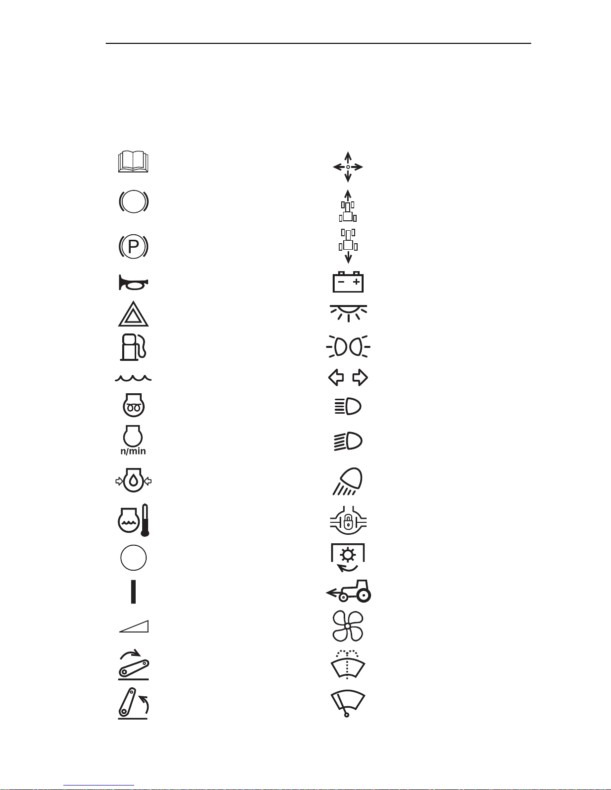
International symbols
The manufacturer uses standard international symbols concerning application of the
devices and controls.
Below are given the symbols with their respective meanings.
— see Manual
— brake
— park brake
— horn
— fault signaling
— fuel
— coolant
— pre-heater glow plug
— engine speed
— controls manipulations
— forward
— back
— battery charging
— interior lamp
— clearance lights
— turn signal lamp
— upper beam
— low beam
— engine oil pressure
— engine coolant temperature
— off/stop
— on/start
— working lights
— differential lock
— power take-off shaft on
— front driving axle on
— gradual change
— fan
— lever down
— lever up
9
— windshield washer
— windshield wiper
Page 7
Introduction Belarus-510/512 Operating manual
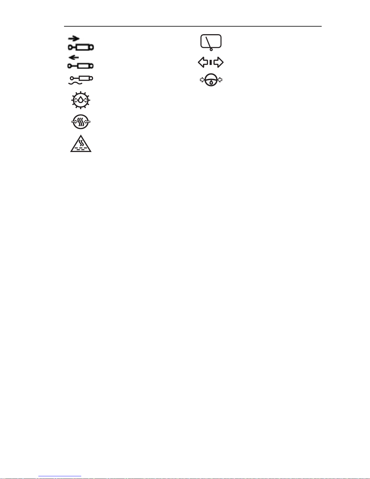
“lift” position of the distributor
—
slide valve
— “drop” position of the
distributor slide valve
— “float” position of the
distributor slide valve
— GB oil pressure
— rear window wiper
— tractor trailer turn signal
— HSU oil pressure
— air pressure in pneumatic
system
— air filter clogging
10
Page 8

Section A. Safety precautions Belarus- 510/512 —Operating manual
• Before you start movement, horn to
Section A. Safety precautions
warn other persons and persons working on
the towed machines.
Strict observance of the safety precautions
and closed following the rules of tractor
operation and management ensures full
safety safe of its operation.
• Do not leave the tractor in motion.
• Before leaving the cab, disengage
the PTO, stop the diesel engine, engage
the parking brake, take out the starter key
and turn off the ground switch.
Safety regulations for operation of the
tractor
• Do not turn off the electrical system
with the ground switch before the diesel
ATTENTION! When starting the diesel-engine and manipulating with the
controls, always be in the cab, sitting
in the driver’s seat.
General instructions
• Carefully read the operator’s manual before using the tractor. Insufficient
knowledge on the control and operation of
the tractor may result in accidents.
• Only specially trained and qualified
operators are allowed to operate the tractor.
• If the tractor equipped with a safety
belt, use it for work. If the tractor is not
equipped with a safety belt, contact your
dealer.
• The tractor cab is for one man, no
passengers are allowed.
• Keep clean all the warning signs. If
the signs are damaged or lost, replace
them with new ones.
• Before you start your work, carefully
inspect the tractor and the towed machine.
Get started only after you make sure they
are fully serviceable. Towed agricultural
machines and transport trailers must have
rigid hitches precluding them from swinging
and hitting the tractor during transportation.
• Before starting the diesel engine, the
parking brake must be engaged, the gearbox shifter must be shifted to the neutral
position, the PTO engaging lever to the off
position.
engine is stopped.
• Do not work on the tractor in a
closed room without adequate ventilation.
G
Exhaust gases can kill you!
• In case of a fault, immediately stop
the tractor and fix the fault.
• In case of a diesel engine or a steering gear failure, immediately stop the tractor. Remember that with the diesel engine
stopped, you have to apply a much greater
force to the steering wheel to control the
tractor.
• Do not work under raised agricultural
implements. During long stops, do not leave
toolbar implements in a raised position.
• If the front of the tractor takes off the
ground when mounting heavy machinery
and implements to the mechanism, attach
front counterweights.
• When working with a front-end loader, fill the rear tires with liquid ballast.
11
Page 9

Section A. Safety precautions Belarus- 510/512 —Operating manual
• Before lifting and lowering an agricultural implement, as well as when making turns, make sure that there is no
hazard to hit someone or run over an
obstacle.
• During transport journeys with
mounted machines or implements, always use the mount lock in the raised
position (for tractors with an autonomous
power cylinder).
• The driveshaft transmitting rotation from the tractor PTO shaft to the aggregated tools of the unit must be guarded.
• Ensure the correct installation of
any additional equipment or auxiliary devices, and make sure that they are designed for use with your tractor. Remember that your tractor, if improperly used,
can be dangerous both for you and for
other persons. Do not use equipment
that is not intended for installation on the
tractor.
• To avoid a tipover, exercise caution when driving the tractor. Choose a
safe speed appropriate to road conditions, especially when driving on rough
terrains, when driving over ditches,
slopes and making sharp turns.
• When working on slopes, increase
the tractor wheel track to the maximum.
• Do not make sharp turns with a
full load and at a high speed.
• When using the tractor for transportation works:
− increase the tractor wheel truck to
1,800 mm (70") min.;
− interlock the brake pedals, check
and adjust as necessary the brakes for
simultaneous action;
− check operation of the parking
brake;
− check the condition of light and
sound signal equipment;
− transportation trailers must have a
solid connection and, in addition, connect a safety chain or rope;
− never drive downhill by coasting
(out of gear), drive at the same gear both
downhill and uphill;
− do not work with a trailer without independent brakes if its weight exceeds
half of the total actual weight of the tractor. The faster you drive and the greater
is the towed weight, the greater must be
the safe distance;
− disconnect the FDA in order to
avoid excessive wear of the drive parts
and tires;
− do not use the rear axle DL at a
speed exceeding 10 km/h and when
making turns;
− the PTO must be off and the simultaneous/independent drive shifter arm
must be in the neutral position;
− do not stop the tractor on slopes. If
you want to stop, engage the 1st gear
and fully engage the parking brake.
• When working with equipment
driven from the PTO, disengage the PTO
before disconnecting the equipment,
stop the diesel engine, make sure the
PTO shaft end is fully stopped.
• Do not wear loose clothing when
working with the PTO or near rotating
equipment.
• When working with stationary machines driven from the PTO, always engage the parking brake and chock rear
wheels from the front and from the rear.
Make sure that the machine is reliably
secured.
• Make sure that the PTO shaft end
guard is installed, and when the PTO is
not used, install the PTO shaft end cap
to place.
12
Page 10

Section A. Safety precautions Belarus- 510/512 —Operating manual
• Do not clean up, adjust or service
the equipment driven from the PTO with
the diesel engine running.
Safety requirements for maintenance
service
• Never refuel the tractor with the
diesel engine running.
• Do not smoke when refueling the
tractor.
• Do not fill the fuel tanks completely. Leave a space for fuel expansion.
• Never add gasoline or blends to
diesel fuel. Such combination may result
in higher hazard of flame or explosion.
• Make proper use of summer and
winter grades of fuel. To reduce the
amount of night condensate, refill the
fuel tank at the end of each working day.
• Refill the tractor only with oils and
greases recommended by the manufacturer. Use of other lubricants is strictly
prohibited!
• All operations related to cleaning
the engine and the tractor, preparation to
work, maintenance, etc. must be performed with the engine off and the tractor
brake engaged.
• The cooling system operates under pressure maintained by a valve installed on the filler cap. It is dangerous
to remove the cap on a hot engine. To
avoid burns of face and hands, take special care when opening the radiator cap
equipment, in good condition to ensure
your safety and that of the surrounding
people.
• Do not modify the tractor or any of
its constituent parts without approval
from you dealer and manufacturer.
Safety requirements for operation and
maintenance of electrical equipment
• To avoid damages to semiconductor devices and resistors, observe the
following precautions:
− do not disconnect the storage battery terminals when the diesel engine is
running. This will result in peak voltage
in the charging circuit and unavoidable
damage of diodes and transistors.
− do not disconnect the electrical
wires until the diesel engine stops and all
electrical switches are switched off;
− do not cause a short circuit due to
faulty connection wires. A short circuit or
wrong polarity will cause damage to the
diodes and transistors;
− do not connect the storage battery
to the electrical system until terminals
and voltage are checked for the polarity;
− do not check availability of electric
current by sparking as it will result in an
immediate breakdown of transistors.
Hygiene requirements:
• If duration of continuous work on
the tractor exceeds 2.5 hours per a working shift, use personal protection equipment to muffle noise as per State Standard ГОСТ 12,4.051-87 (such as ear protectors, ear plugs)
on a hot engine, put a thick cloth onto
the cap first and put on a glove.
• To avoid burns, be careful when
draining the coolant from the cooling system, hot oil from the diesel engine, hydraulic system and transmission.
• Exercise caution while servicing
storage batteries as electrolyte causes
burns in case of skin contact.
• To avoid risk of explosion, do not
allow a source of open fire near the fuel
system of the engine and batteries.
• Keep your tractor and its equipment, especially the brakes and steering
Fire safety requirements
• The tractor must have firefighting
tools such as a shovel and a fire extinguisher. Working on the tractor without
fire-fighting equipment is prohibited.
• The tractor park sites, fuel and
lubricant storage places must have a
surrounding plowed strip with a width of
3 m min. and be provided with firefighting means.
• Avoid contamination of the manifold and silencer with dust, fuel, straw,
etc.
13
Page 11

Section A. Safety precautions Belarus- 510/512 —Operating manual
• Do not allow straw to be taken up
by rotating parts of the machines attached to the tractor.
• When rinsing parts and assemblies with kerosene or gasoline, take
precautions to exclude ignition of vapors
of the rinsing fluid.
• Do not operate the tractor in places of high fire hazard with the hood and
other protective devices removed from
hot parts of the engine.
• Do not use open fire to heat up oil
in the diesel engine pane, to burn out
contamination of the radiator core.
• If there appears a seat of fire,
dump sand over it, cover with tarpaulin,
sackcloth or any other dense cloth. Use
a carbon-dioxide fire extinguisher. Do not
extinguish burning fuel with water.
• When the engine is running, keep
inflammable materials away from the exhaust manifold and muffler.
• When making hay and straw or
working in places with high fire hazard,
use spark arresters in the exhaust system complete with a silencer or separated from it.
14
Page 12
Section B. Specifications Belarus-510/512 Operating manual
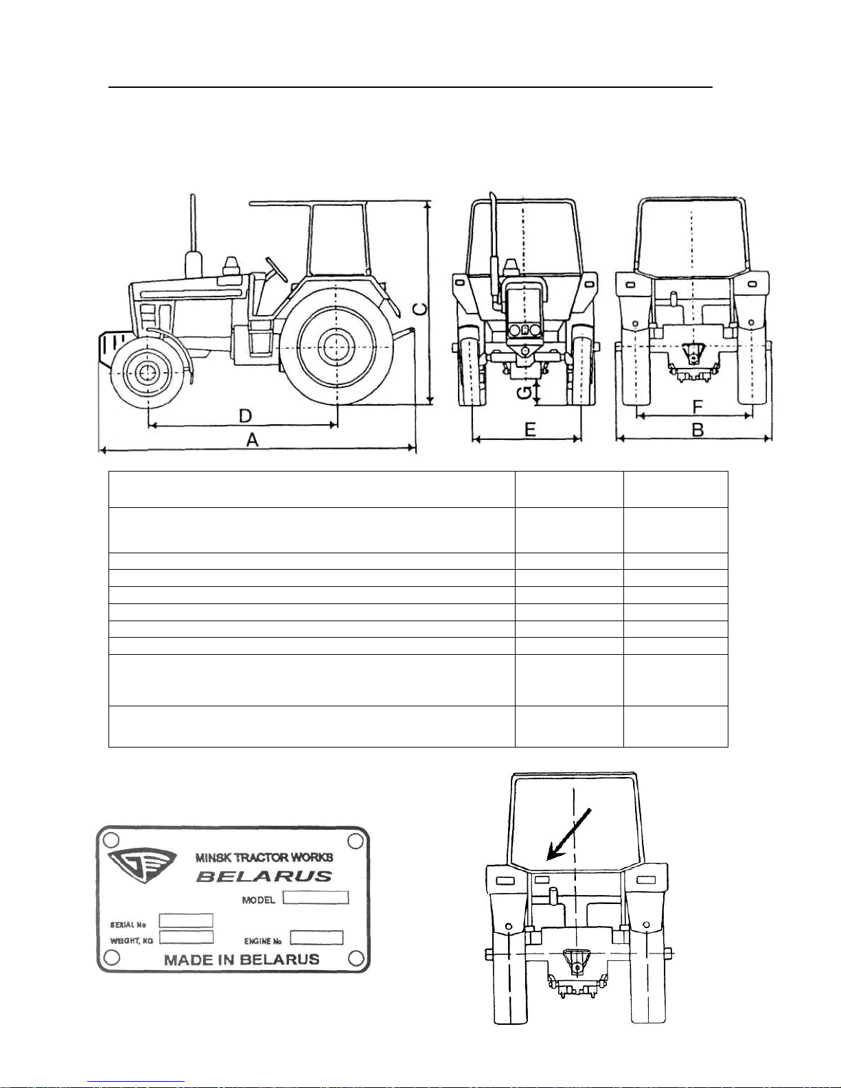
A Length, mm: total (with counterweights)
:
by wheels
4,120
3,650
4,120
3,740
В Width, mm
1,970
1,970
С Height by cab, mm
2,780
2,800
D
Wheel
base, mm
2,370
2,450
F Rear track, mm
1,400
- 1,600
1,800
- 2,100
E
Front track, mm
1,350
- 1,850
1,400
- 2,000
G
Road clearance, mm
465 465
9.00
-
20,
11.2
-
20,
Section B. SPECIFICATIONS
Weight and Overall Dimensions
C
Name
without counterweights
Tire size: front wheels / rear wheels
510 512
3,840
9.00R20/
15.5R38
Service weight, kg 3,460 3,690
Tractor component Nos.
Manufacturer’s nameplate with tractor and diesel
engine serial Nos. indicated
3,930
11.2R20/
15.5R38
15
Page 13
Section B. Specifications Belarus-510/512 Operating manual
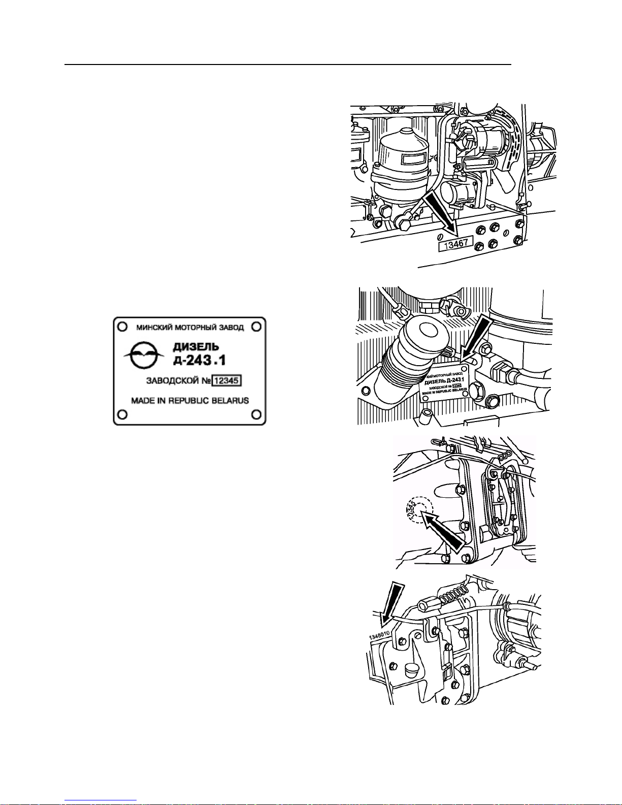
The serial number of the tractor is duplicated
on the front part of the right half-frame side
member (or on the right plate of the front
counterweights).
Diesel engine serial No. (duplicated on the
manufacturer’s nameplate of the engine attached to the cylinder block, on the lefthand side).
Clutch No. (on the left-hand side of the
clutch housing).
Gearbox No. (on the left-hand side of the
GB housing)
16
Page 14
Section B. Specifications Belarus-510/512 Operating manual
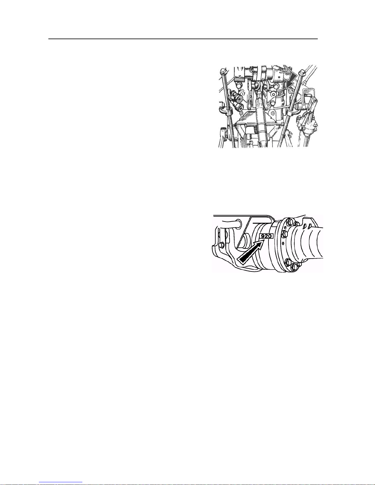
Transmission number (on the rear axle housing from behind).
Front driving axle number (on the front
part).
17
Page 15

Section B. Specifications Belarus-510/512 Operating manual
Diesel engine
Engine model Д-244
Type four-stroke, in-line, naturally aspirated
Number of cylinders 4
Mixing method Direct injection
Compression (calculated) 16
Cylinder bore, mm ( " ) 110 (4.32)
Stroke, mm ( " ) 125 (4.92)
Cylinder displacement, l (cu. in.) 4.75 (290)
Operation order 1—3—4—2
Cooling system; liquid
Rated speed, rpm 1,700
Maximum speed, rpm 1,850
Minimum speed, rpm 600
Rated power, kW 41.9
at 1,700 rpm
Maximum torque, N•m 271 at 1,400 rpm
Clearance between intake and exhaust valves and rockers at cold engine, mm
Advance angle of fuel injection before
upper dead center (UDC), degrees
Fuel injection pressure, MPa
(kgf/cm²)
0.20…0.35
20 ± 1
21.6…22.4
(220 … 228)
18
Page 16

Section B. Specifications Belarus-510/512 Operating manual
Engine lubrication system
Type: combined with oil radiator.
Minimum oil pressure:
0.08 MPa (0.8 kgf/cm²) at 600 rpm.
Normal oil pressure:
0.2...0.3 MPa (2…3 kgf/cm²).
Max. pressure at cold diesel engine: up
to 0.6 MPa (6 kgf/cm²).
Capacity of lubrication system: 12 l
Motor oil grades:
- –40°С to +5°С: M-8ДM; M-8Г2,
M-8Г2K or M43/8Г2 (SAE-20,
SAE 10W-20);
- +5°С to +50°С: M-10ДM; M-10Г2; M10Г2K (SAE-30);
- multigrade oil: SAE 15W-40.
Engine feed system
Fuel pump: 4-plunger type, in-line, with
booster pump.
Governor: mechanical, variable-speed.
Fuel filters: coarse and fine filter (with a
replaceable filter element ФT 020 -
1117010).
Fuel grade: Diesel fuel: summer grade
Л-0.2-40, Л-0.5-40; winter grade З-0.2, З-
0.5.
Fuel tanks capacity: 120 l
Air cleaner: combined with dry centrifugal
and oil-bath air cleaning.
Maximum working pressure in system:
9.0 ± 0.05 MPa.
Oil grades:
- –40°С to +5°С: M-8ДM; M-8Г2,
M-8Г2K or M43/8Г2 (SAE-20,
SAE 10W-20);
- +5°С to +50°С: M-10ДM; M-10Г2; M10Г2K (SAE-30);
- multigrade oil: SAE 15W-40.
Steering wheel position control limits:
· by tilt: from 25° to 40° with fixation
through 5°;
· by height within 100 mm.
Steering wheel free play: 25° max.
Engine start system
12 V electric starter.
Engine cooling system
Type: closed with forced coolant circula-
tion, temperature controlled by thermostatic regulator.
Normal operating temperature: 80°C to
100°C.
Cooling system capacity: 20 l.
Clutch
Air cleaner oil bath capacity: 1.5 l.
Steering
Booster type: hydromechanical.
Steering mechanism: worm, helical gear
sector and steering booster.
Pump type: gear pump
НШ10–3–Л.
Pump capacity: 21 l/min
Type: friction, dry, single-disk, spring-
loaded.
Driven disk diameter — 340 mm.
19
Page 17
Section B. Specifications Belarus-510/512 Operating manual
Gearbox
Type: (standard)
9F/2R
, mechanical.
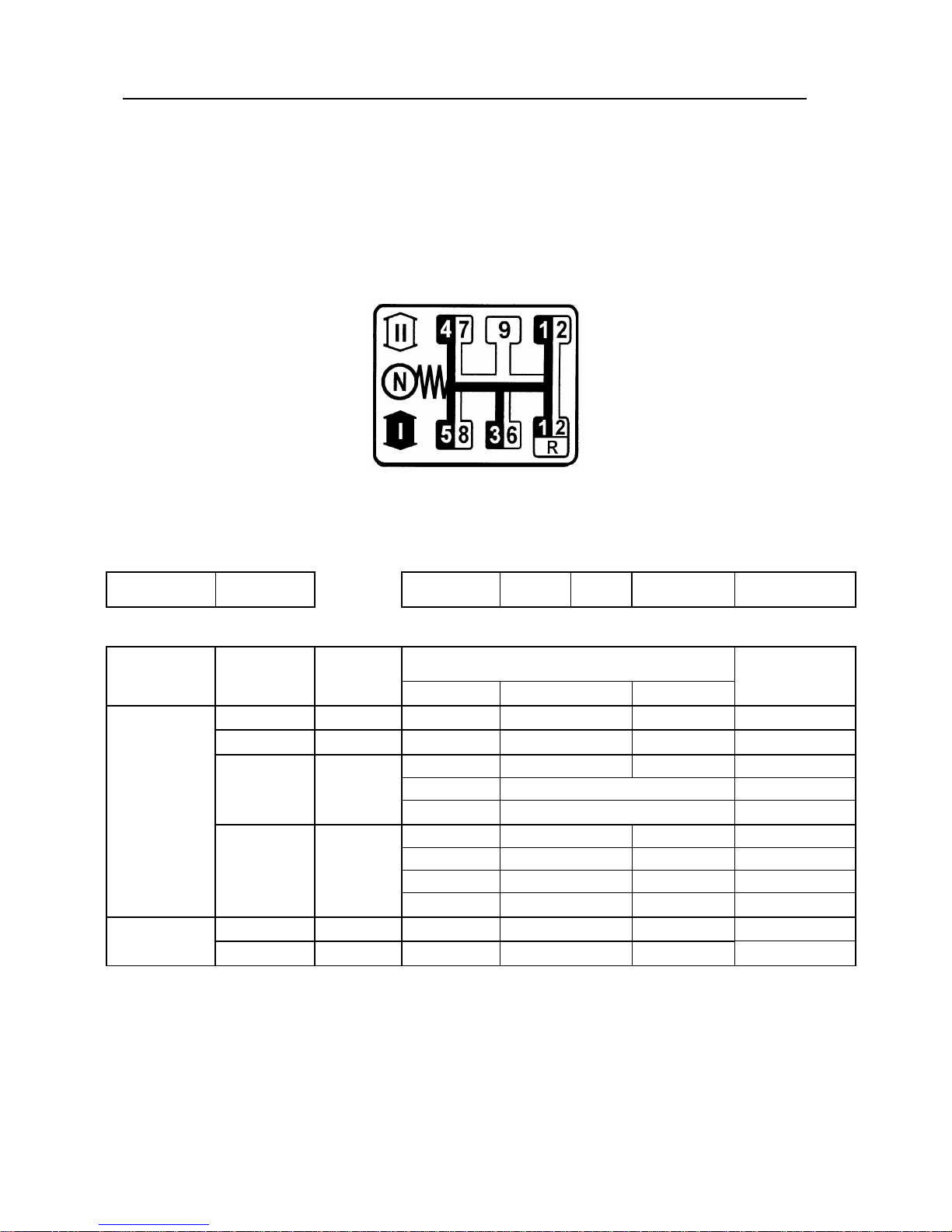
Gear and range shift pattern
Rated speeds (km/h) of the BELARUS — 510/512 tractors
Rated engine
speed, rpm
Motion
front 1 I 2.2500
2 II 1.3214
3 I 2.2500
4 2.2500
5 2.2500
6 II 1.3214
7 1.3214
8 1.3214
9 1.0000
reverse 1R I 2.2500
2R II 1.3214
1,700
No. of
gear
No. of
range Gear ratio V tr, km/h
R k, m 0.75 I zm 18.1346
range GB transmission
5.9298
5.9298
2.0476
1.6667
1.4074
2.0476
1.6667
1.4074
1.0000
2.8166
2.8166
241.9512
142.0983
83.5488
68.0048
57.4263
49.0683
39.9393
33.7265
18.1346
114.9268
67.4967
1.9866
3.3826
5.7531
7.0681
8.3701
9.7958
12.0348
14.2518
26.5053
4.1823
7.1213
(standard, equipped with 15.5R38 tires)
20
Page 18

Section B. Specifications Belarus-510/512 Operating manual
Fig. 1. Gearbox of BELARUS-510/512 tractor (9F/2R)
1 — drive pinion of 4th and 5th gears; 2 — fork of 4th and 5th gears; 3 — forks housing; 4
— fork of 3rd and 6th gears; 5 — drive pinion of 3rd and 6th gears; 6 — output shaft with
driven pinion of Ist stage of range reducer; 7 — gear shifter lever; 8 — reducer fork; 9 —
reducer shaft; 10 — GB lever handle; 11 — GB control cover; 12 — restrictive plate; 13 —
adjustment shims; 14 — body; 15 — drive pinion of rear axle final drive; 16 — driven pinion of IInd stage of range reducer; 17 — inner shaft; 18 — seat with bronze bushings; 19
— impeller; 20 — body; 21 — drive pinion of Ist stage of range reducer; 22 — drive pinion
of Ith stage of range reducer; 23 — intermediate pinion; 24 — driven pinion of 3rd and 6th
gears; 25 — driven pinion of 4th and 7th gears; 26 — driven pinion of 5th and 8th gears
and reverse gears; 27 — GB housing; 28 — seat: 29 — intermediate shaft; 30 — body; 31
— input shaft; 32 — glass
21
Page 19
Section B. Specifications Belarus-510/512 Operating manual
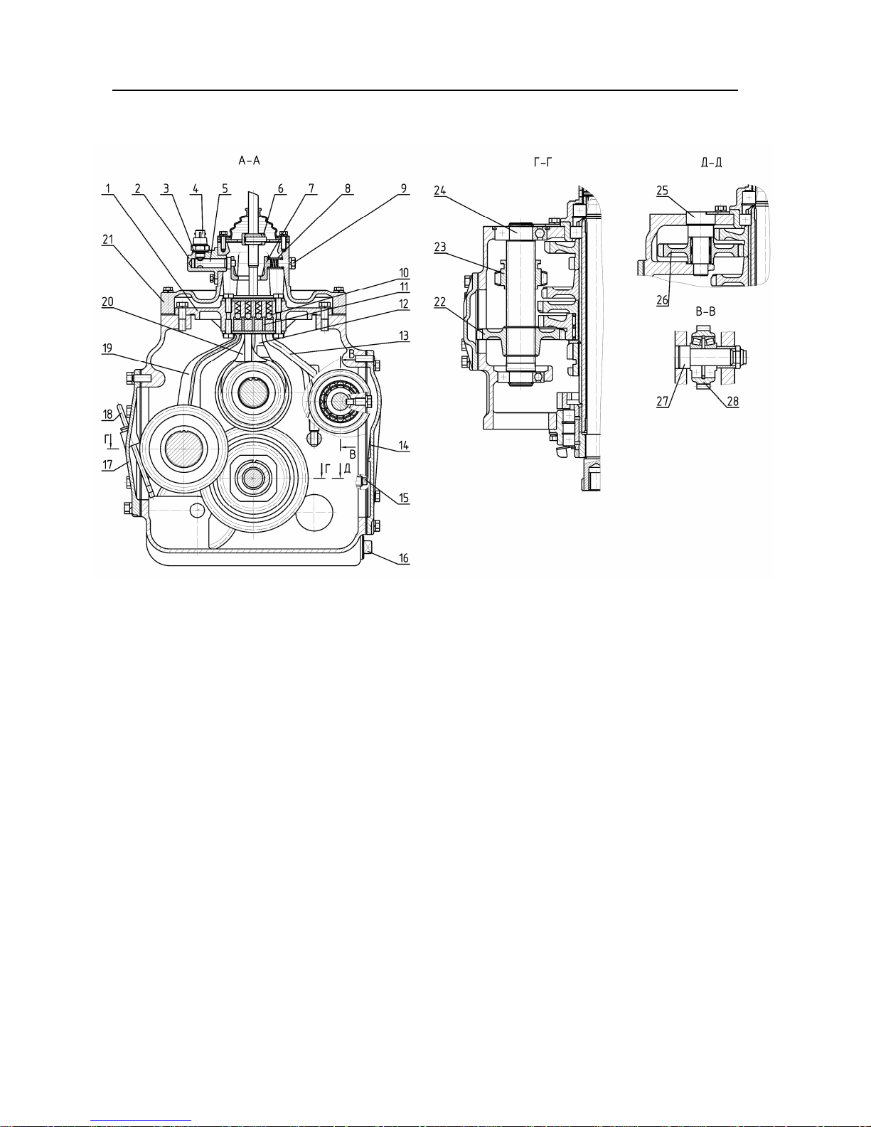
Fig. 2. Gearbox of BELARUS-510/512 tractor (9F/2R)
1 — forks housing; 2 — housing; 3 — adjustment shims; 4 — engine start lock sensor; 5
— axle of frame; 6 — ball bearing; 7 — frame; 8 — spring; 9 — bolt; 10 — lever; 11 —
ball; 12 — lock strips; 13 — fork of 4th and 5th gears; 14 — range reducer rod; 15 — cover; 16 — check plug; 17 — drain plug; 18 — cover; 19 — oil dipstick; 20 — fork of 1st gear
and reverse gears; 21 — fork of 3rd and 6th gears; 22 — GB cover; 23 — driven pinion of
hill-climbing gears and reverse gears; 24 — pinion of hill-climbing gears and reverse
gears; 25 — shaft of 1th gear and reverse; 26 — FDA drive pinion axle; 27 — reverse intermediate gear; 28 — FDA drive pinion axle; 29 — FDA drive pinion
Gearbox
The gearbox (GB) is an element of the tractor transmission serving to change the
transmission gear ratios and reverse the tractor movement, thus achieving the required
speed range of the tractor (see Table 1), as well as for long-term disengagement of the
engine and the tractor propeller.
Besides, the GB design provides driving the front drive axle (FDA) of the tractor
and synchronous rear power take-off shaft (PTO).
The BELARUS-50/52 tractors and their modifications have a mechanical fixed-ratio
dual-range 9F/2R GB with a central position of the GB control lever, the design and operation of which are described below.
22
Page 20

Section B. Specifications Belarus-510/512 Operating manual
1.1 GB design
The GB (Fig. 1 and 2) consists of the mechanical gears unit and GB control.
1.1.1 Mechanical gears unit
The mechanical gears unit of the GB consists of the concentric input (31) and output (6) shafts located in the
GB housing (27) (Fig. 1)
*
, as well as an intermediate shaft (29)
parallel to them and the shaft of 1st gear and reverse (24) (Fig. 2).
The input shaft (31) (Fig. 1) is mounted on two ball bearings one of which is placed
in the body (32) on the front wall of the GB housing (27). The second one is in the boring
of the output shaft (6). On the input shaft, a double-wheel drive pinion of 4th and 5th gears
(1) and a drive pinion of 3rd and 6th gears (5) with possibility of axial sliding movement
along the shaft splines are installed.
The output shaft supports (6) (Fig. 1) are two tapered roller bearings, one located in
the GB housing boring (27), and the second in the body (14) installed in the boring of the
rear wall of the GB housing (27). Structurally, the output shaft is made as one piece with
the driven pinion of Ist stage of the range reducer. The gear ring is located cantilevered in
front of the output shaft (6). Between the supports of the output shaft, the driven pinion of
IInd stage of the range reducer (16) is installed fixed on the splines, which is also the drive
pinion of the rear PTO synchronous drive. On the rear arm of the output shaft, the drive
gear (15) of the rear axle final drive (small bevel pinion) is installed fixed on the splines.
On the intermediate shaft (29), fixed on the splines are installed the double-wheel
driven pinion of 5th and 8th gears and reverse gears (26), driven pinion of 4th and 7th
gears (25), and driven pinion of 3rd and 6th gear (24), on the hub of which the doublewheel intermediate pinion (23) is freely rotating on needle roller bearings, being in constant
mesh with the pinion (22) (Fig. 2) installed on the shaft of 1st gear and reverse gears (24).
On the intermediate shaft (29) (Fig. 1), with the possibility of axial movement the drive pinion (22) of Ist stage
of the range-reducer is installed.
The front support of the intermediate shaft (29) is a ball bearing located in the body
(30) of the front wall of the GB housing (27). The rear support of the intermediate shaft is a
bronze bushing installed in the boring of the drive pinon (21) of IInd stage of the rangereducer.
The driven pinion of IInd stage of the range-reducer (21) is freely rotating on two
bearings located in the body (20) installed in the boring of the rear wall of the GB housing
(27). The pinion (21) has an inner and outer gear rings, as well as cams located on its rear
end, which serve to synchronously drive the rear PTO. In the boring of the pinion (21), the
seat (18) with bronze bushing is fixed with a pin, which is the rear support of the inner
shaft (17). Outside on the pinion (21), the impeller (19) is fixed, which by intensive spraying improves lubrication of the pinions of the final drive and the rear axle differential of the
tractor.
The 1st gear and reverse shaft (24) (Fig. 2) is installed on two ball bearings located
in the GB housing borings. In the front of the shaft (24) on splines, the sliding pinion (23) of
hill-climbing gears and reverse gears is installed. Backward movement of the sliding pinion
(23) up to meshing with the pinion (25) (Fig. 1) provides forward hill-climbing gears, and
forward movement up to meshing with the intermediate pinion of reverse motion (26) (Fig.
2) provides reverse gears. The intermediate reverse pinion (26) is installed on the axle
(25) and is freely rotating on it on a needle roller bearing. The pinion (26) is in constant
mesh with the smaller gear ring of the double-wheel gear (26) (Fig. 1).
*
theses immediately after the position designation; if such an indication of the figure is absent, the position designation refers to the last figure mentioned in the preceding text.
Hereinafter, a position designation refers to the figure with the number indicated in paren-
23
Page 21

Section B. Specifications Belarus-510/512 Operating manual
At the rear part of the shaft (24) (Fig. 2), fixed on its splines, the driven pinion of hillclimbing gears and reverse gears (22) installed, which is constantly meshed with the
smaller gear ring of the pinion (23) (Fig. 1) of the intermediate shaft (29).
On the right side of the GB of the tractors with FDA drive, the axle (27) is installed in
the GB housing borings, on which on two tapered roller bearings the FDA drive pinion (28)
is freely rotating. Power is taken off at the FDA from the driven pinion of Ist stage of the
range reducer (6) (Fig. 1), with which the pinion (28) (Fig. 2) is constantly meshed.
On the front wall of the GB housing (27) (Fig. 1), concentrically to the intermediate
shaft (29), the seat (28) is installed, inside of which the inner shaft front bearing (17) is located.
On the right and left sides of the GB housing, there are windows (Fig. 2). The left
window is closed with the cover (17), in which there is a dipstick (18) to control the oil level. The tractors without an FDA drive have the right window closed with the cover (14), and
the tractors with the FDA drive have the cover (14) removed and the window closed by the
FDA drive transfer box housing (see section).
To drain oil when changing it, a hole is provided in the bottom of the GB housing,
closed with the plug (16).
1.1.2 GB control
The GB control consists of the forks housing (3) (Fig. 1) and the GB control cover
(11) that are installed on the upper plane of the GB housing (27) and bolted to it.
The forks housing (3) (Fig. 1 consists of the fork of 1st gear and reverse gears (19)
(fig. 2), the fork of 3rd and 6th gears (20), the fork of 4th and 5th gears (12) and the range
reducer rod (13), the rails of which are installed in the groove of the housing (1) and can
move along the groove. On the upper surfaces of the rails, there are transverse holes in
which the spring-loaded balls of the latches (10) are inserted, which provide locking of the
forks rails and reducer rail in the desired positions, as well as prevent spontaneous disengagement of the gears under load.
The rod (13) is connected with the shaft (9) (Fig. 1), on which the fork (8) is fixed
that moves the drive pinion of Ist stage of the range reducer (22).
The forks and range reducer rails are separated by three lock strips (11) (Fig. 2).
The strips (11) are installed in the housing (1) fixed and exclude simultaneous movement
of several rails by the gear shifter lever (7) (Fig. 1). When a gear is engaged, the lock
strips (11) lock the gear shifter lever (7) (Fig. 1) in the rail groove of the fork of the gear
engaged.
The GB control cover (11) consists of the cover (21) (Fig. 2), on the upper surface
of which the spherical bearing (6) of the gear shifter lever (7) (Fig. 1) is bolted. When
swinging, the gear shifter lever (7) directly affects the rails in the forks housing (3), causing
their displacement and, consequently, engagement or disengagement of the selected gear
or range in the GB.
To avoid excessive swinging of the gear shifter lever (7), as well as to clearly direct
its motion, the restrictive plate serves (12), which is bolted to the cover (11).
The GB design provides an engine start lock when a gear is engaged in the GB. On
the right side of the cover (21) (Fig. 2), the housing is installed (2) bolted to it. In the housing (2), the axle (5) of the spring-loaded rocking frame (7) is located. The ring hole of the
frame (7) envelops the gear shifter lever (7) (Fig. 1). At that, rocking of the lever (7) results
in a corresponding movement of the frame (7) (Fig. 2), the axle flat (5) of which affects the
diesel start lock sensor (4) mounted in the threaded hole of the housing (2).
Triggering of the engine start lock is adjusted by the shims (3) located under the
24
Page 22

Section B. Specifications Belarus-510/512 Operating manual
sensor (4).
1.2 GB operation
The 9F/2R GB design provides 4 forward gears and one reverse gear, each of them
can be engaged on the both range reducer stages, and one direct forward gear, at engagement of which the input (31) (Fig. 1) and output (6) shaft are rigidly linked by the drive
pinion of 3rd and 6th gears (5) acting as a gear-type coupling at that.
The GB gears and ranges are engaged by a single GB control lever (7) as per the
diagram (Fig. 3). Selection of gears in the GB is preceded by selection of the desired
range of the reducer.
Gears and ranges are switched only when the tractor stopped and the clutch pedal
is pressed on.
To select and engage a reducer range, the operator shifts the gear shift lever (7)
(Fig. 1) from the neutral position to the range-reducer position (Fig. 3). Further, to engage
the Ist reducer stage, the operator shifts the GB control lever (7) (Fig. 1) backwards (Fig.
3). At that, the gear shifter lever (7) (Fig. 1), acting on the reducer rail (13) (Fig. 2), moves
it and its associated roller (9) (Fig. 1) with the fork (8) forward. The drive pinion of Ist reducer stage (22) controlled by the fork (8) moves along he intermediate shaft splines (29)
and engages with the driven pinion (6) of Ist range reducer stage.
To engage the IInd reducer stage, the operator shifts the GB control lever (7) (Fig.
1) in the range reducer position forward (Fig. 3). At that, the gear shifter lever (7) (Fig. 1),
acting on the reducer rail (13) (Fig. 2), moves it and its associated roller (9) (Fig. 1) with
the fork (8) forward. The driven pinion of Ist reducer stage (22) controlled by the fork (8)
moves along he intermediate shaft splines (29) and engages with the inner gear ring of the
drive pinion (21) of IInd range reducer stage, linking it to the intermediate shaft (29). The
pinion (21) is in constant mesh with the driven pinion of the IInd range reducer stage (16).
At the IInd range reducer stage, rotation from the intermediate shaft (29) is transmitted to the output shaft (6) with deceleration less than at the Ist stage.
In the GB range reducer, there is no neutral position of the drive pinion of the Ist reducer stage (22) (Fig. 1), therefore either the Ist or the IInd stage is always turned on in the
range reducer.
To engage the 1st or 2nd forward or reverse gear, the operator shifts the GB control
lever (7) (Fig. 1) to the extreme left position (Fig. 3) being the position of hill-climbing gears
and reverse gears. Further, to engage the 1st or 2nd forward gear, the operator shifts the
GB control lever (7) (Fig. 1) forward (Fig. 3). At that, the gear shifter lever (7) (Fig. 1), acting on the rail of the fork of the 1st gear and reverse gear, moves the fork (19) (Fig. 2)
backward. The sliding pinion of 1st gear and reverse motion (23) controlled by the fork (19)
engages with the driven pinion of 4th and 7th gears (25) (Fig. 1), and power in the GB is
transmitted to the ?GB intermediate shaft (29) through the pinions (5), (23), (22) (Fig. 2),
(23) and (25) (Fig. 1).
To engage the 1st or 2nd reverse gear, the operator shifts the GB control lever (7)
(Fig. 1) to the position of hill-climbing gears and reverse gears backward (Fig. 3). At that,
the gear shifter lever (7) (Fig. 1), acting on the rail of the fork of the 1st gear and reverse
gear, moves the fork (19) (Fig. 2) forward. The sliding pinion of 1st gear and reverse motion (23) controlled by the fork (19) engages with the intermediate pinion of reverse gear
(26) being in constant mesh with the lesser gear ring of the double-wheel pinion of 5th and
8th gears (26) (Fig. 1). At the reverse gear, power flow in the GB is transferred to the intermediate shaft (29) through the pinions (5), (23), (22) (Fig. 2), (23), (26) and (26) (Fig. 1).
To engage the 3rd and 6th, or 9th (direct) gear, the operator shifts the GB control
25
Page 23

Section B. Specifications Belarus-510/512 Operating manual
lever (7) (Fig. 1) to the respective positions of those gears (Fig. 3). Further, to engage the
3rd (6th) gear, the operator shifts the GB control lever (7) (Fig. 1) to the position of the said
gears backward (Fig. 3). At that, the gear shifter lever (7), acting on the rail of the fork of
4th and 5th gears, moves the fork (20) (Fig. 2) forward. The sliding pinion of 3rd and 6th
gears (5) controlled by the fork (20) (Fig. 1) engages with the driven pinion of 3rd and 6th
gears (24). By the emerged mesh, power is transferred to the GB intermediate shaft (29).
To engage the 9th (direct) gear, the operator moves the GB control lever (7) (Fig. 1)
from the position of the 3rd (6th) and 9th (direct) forward gears (Fig. 3). At that, the gear
shifter lever (7), acting on the rail of the fork of 3rd and 6th gears, moves the fork (20) (Fig.
2) forward. The sliding pinion of 3rd and 6th gears (5) controlled by the fork (20) (Fig. 1)
engages with the inner gear ring of the output shaft (6), rigidly linking the input (31) and
output (6) shafts.
The 9th (direct) gear must be engaged when the IInd range reducer stage is engaged (Fig. 3).
shaft speed (29) (Fig. 1) less than the Ist stage.
This will avoid a loud noise in the GB, since the IInd reducer stage has an intermediate
To engage the 4th (7th) or 5th (8th) gear, the operator shifts the GB control lever (7)
(Fig. 1) to the respective positions of those gears (Fig. 3). Further, to engage the 4th or 7th
gear, the operator shifts the GB control lever (7) (Fig. 1) to the position of the said gears
forward. At that, the gear shifter lever (7), acting on the rail of the fork of 4th and 5th gears,
moves the fork (12) (Fig. 2) and the drive pinion unit of 4th and 5th gears (1) controlled by
it (Fig. 1) backward. The smaller gear ring of the unit (1) engages with the driven pinion of
4th and 7th gears (25). By the created mesh, power from the input shaft (31) is transferred
to the GB intermediate shaft (29).
To engage the 5th or 8th gear, the operator shifts the GB control lever (7) (Fig. 1) to
the position of the said gears backward (Fig. 3). At that, the gear shifter lever (7), acting on
the rail of the fork of 4th and 5th gears, moves the fork (12) (Fig. 2) and the drive pinion
unit of 4th and 5th gears (1) controlled by it (Fig. 1) forward. The larger gear ring of the unit
(1) engages with the driven pinion of 5th and 8th gear (26). By the created mesh, power
from the input shaft (31) is transferred to the GB intermediate shaft (29).
Table 1 shows rated speeds of the BELARUS-510/512 tractor and its modifications
at all GB gears.
26
Page 24
Section B. Specifications Belarus-510/512 Operating manual
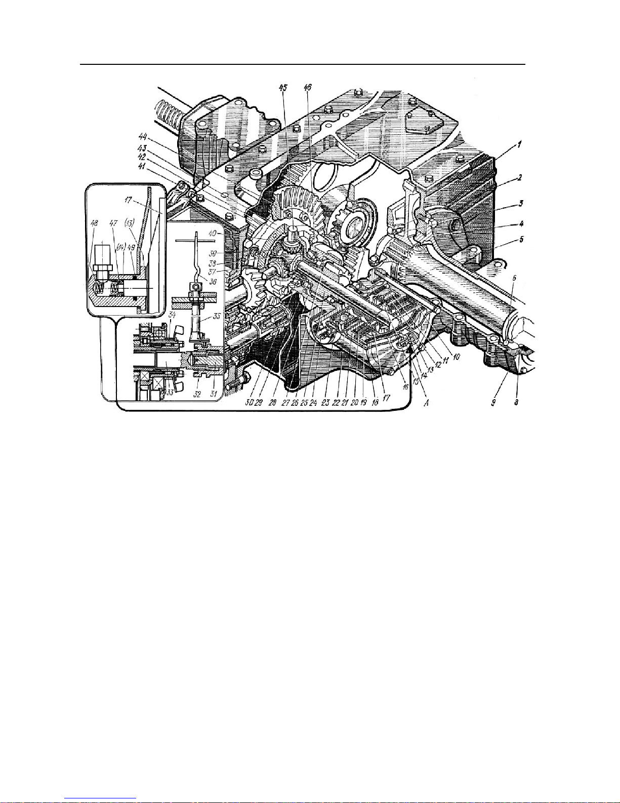
Rear axle:
1 — housing; 2 — half-axle bearing (217); 3 — final drive driven pinion; 4 - half-axle
tube; 5 — half-axle; 6 — half-axle bearing (217); 8 — cover; 9 — cup; 10 — expansion
springs; 11 — pressure plate; 12 — brake disk; 13 — adapter; 14 — ring; 15 — return
springs; A — working cavity of lockup clutch; 16 — diaphragm cover; 17 — plate; 18 —
pressure plate; 19 — diaphragm; 20 — intermediate disk; 21 — clutch housing
of DL; 22 — DL clutch casing; 23 — brake casing; 24 — fork; 25 — left drive pinion of
final drive; 26 — adjustment shims; 7 — DL clutch shaft; 28 — left bearing body; 29 —
bearings of drive pinion of final drive; 30 — left bearing of differential (7215A); 31 —
crown pinion shaft; 32 — clutch; 33 — inner shaft; 34 — pinion of synchronous PTO; 35
— control roller; 36 — PTO lever; 37 — half-axle pinion; 38 — support washer of halfaxle pinion, 39 — differential cap; 40 — pinion; 41 — right drive pinion of final drive; 42
— ball washer of pinions; 43 — differential housing; 44 — driven pinion of final drive; 45
— cross; 46 — tight-fitting bolts of differential housing; 47 — bushing; 48 — spring; 49
— ring.
27
Page 25

Section B. Specifications Belarus-510/512 Operating manual
Independent drive:
Rear axle:
Main drive: a pair of bevel gears with cir-
cle-arc tooth.
Differential: bevel, four-pinion.
Final drive: pair of spur pinions.
Differential lock:: hydraulically operated
dry friction clutch
• 540 rpm at 1,630 rpm of engine;
Synchronous drive: 3.4 revolutions per
meter when rear tires 15.5 R38 are installed.
Removable PTO end:
8 splines for 540 rpm
Direction of rotation: clockwise as viewed
from the end butt.
as per SAE with 6 and
Brakes
Sevice: on rear wheels: two-disk type, dry,
with mechanical drive.
Disk diameter: 204 mm.
Parking: disk-type, dry, with mechanical
hand drive.
Disk diameter: 180 mm.
Pneumatic system
Compressor
Type: single cylinder, air cooling.
Front driving axle
Type: portal, with retractable housings of
bevel wheel reduction gears.
Main drive: pair of bevel pinions with circlearc teeth.
Differential type: bevel, self-locking, limitedslip with friction clutches.
Final drives: with bevel reduction gears.
Transmission oils: Taп-15В, TСп-15K or
TСп-10 (SAE 80W-90);
TAД-17И.
Drive: from transfer case with two
driveshafts with intermediate bearing.
FDA control: mechanical, lever under operator’s right hand. Has 3 operating modes:
FDA disengaged;
FDA engaged/disengaged automatically;
FDA engaged forced.
Power take-off shaft drive
(PTO)
Type: independent one-speed and synchro-
nous.
Master clutch: planetary gear reducer with
belt brakes.
PTO control: mechanical.
PTO end speed:
Hydraulic system
Type: universal, modular, with autono-
mous power cylinder.
Maximum pressure in hydraulic system
180…200 kgf/cm².
Distributor:
spool-type valve:
• Р80-3/1-222-ЗГг (Р80-3/1-111-ЗГг) —
for tractors without a power governor;
Hydraulic system outlets: two side and
two rear outlets.
The RHL control system has an operating mode:
• height.
Hydraulic system oil grades:
• –40°С to +5°С - M-8Г2K
(SAE 15W-40); ВЕСНЕМ STAROIL No.
32;
• +5°С to +50°С - M-10Г2, M-10Г2K
(SAE 15W-40); ВЕСНЕМ STAROIL No.
32;
Rear hitch linkage
Type: three-point mounted system of cat-
egory 2
Lifting capacity: 3200 kg at ends of longitudinal rods.
Electric equipment
Electrical system voltage: 12 V.
Start system voltage: 12V.
Power system: two batteries, 12 V each,
connected in parallel.
Alternator
14 V, 1,150 W
Emergency and light signaling system:
• front headlights with upper and lower
beams;
• rear operating headlights;
• clearance lights and brake lights;
28
Page 26

Section B. Specifications Belarus-510/512 Operating manual
• instrument panel, number plate illumination;
• emergency light.
1,000 rpm
Wheels
Front:
9.00-20 (9.00R20) with a front axle,
11.2-20 (11.2R20) with PTO - 72,
Rear:
15.5R38;
29
Page 27
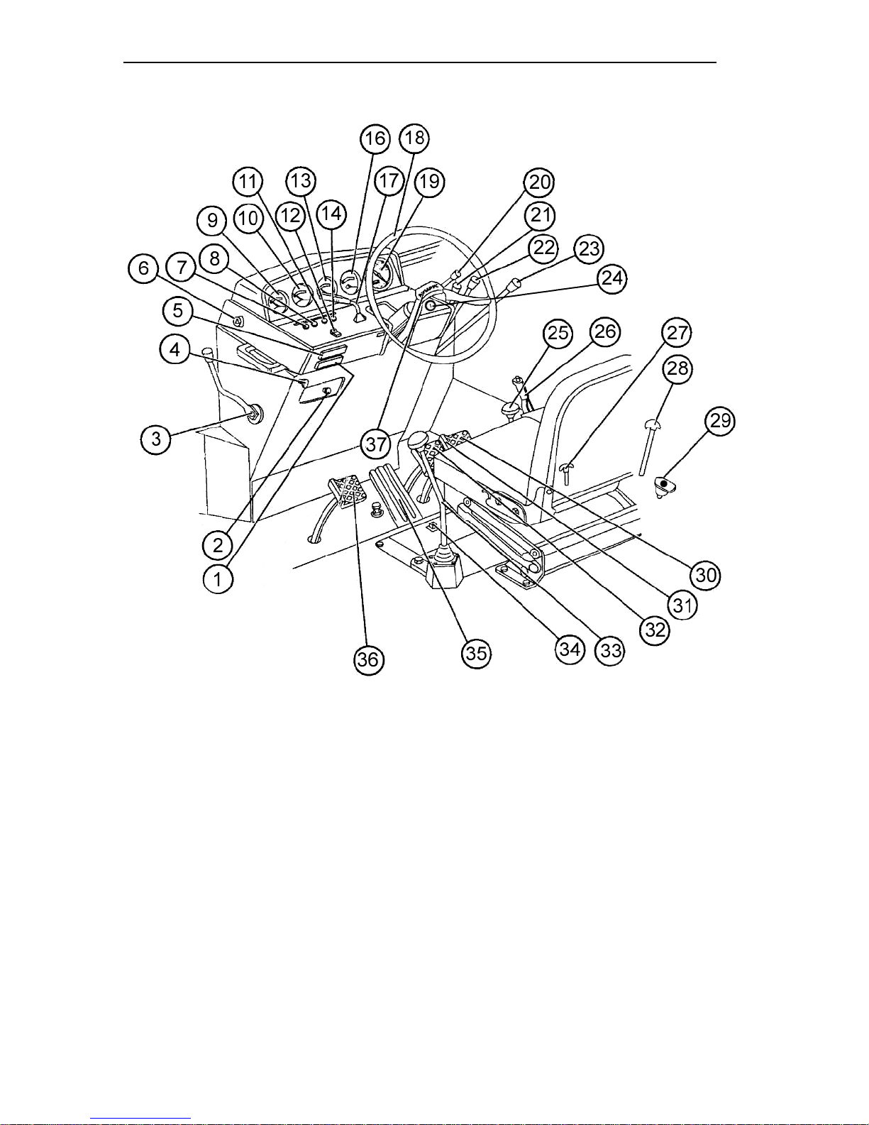
Section C. Controls and Instrumentation Belarus – 510/512 Operating manual
Section C. Controls and Instrumentation
1. Lower fuse block;
2. Engine stop lever;
3. Fuel control lever;
4. Differential lock control knob;
5. Upper fuse block;
6. Emergency stop signaling switch;
7. Alarm lamp of emergency oil pressure drop
in engine (red);
8. Alarm lamp of air filter clogging (red);
9. Engine coolant temperature indicator;
10. Voltage indicator;
11. Turn signal pilot lamp (green);
12. Central light switch;
13. Tank fuel level indicator;
14. Upper beam pilot lamp (blue);
16. Engine oil pressure indicator;
17. Multifunctional understeering switch, (turn
indicators, upper/lower beam, horn, upper
beam signaling);
18. Steering wheel;
19. Tachometer/speedometer;
20. Steering wheel inclination control;
21, 22, 23. Hydraulic system distributor con-
30
trols
24. Starter switch;
25. Rear PTO control lever. Has two positions:
lower – PTO off, upper — PTO on.
26. Parking brake control lever;
27. Transfer case control rod;
28. Mount lock control lever;
29. Battery disconnect switch;
30, 32. Brake pedals;
31. Brake pedal connection plate;
33. Gear shifter lever;
34. PTO drive mode shifter arm. Has three positions: Synchronous drive – Neutral — Independent drive;
35. Fuel control pedal;
36. Clutch pedal;
37. Steering wheel height control mechanism
cover.
Page 28
Section C. Controls and Instrumentation Belarus – 510/512 Operating manual
IMPORTANT! Before you start operating the tractor, study the controls and instru-
mentation and their functions.
Instruments and switches
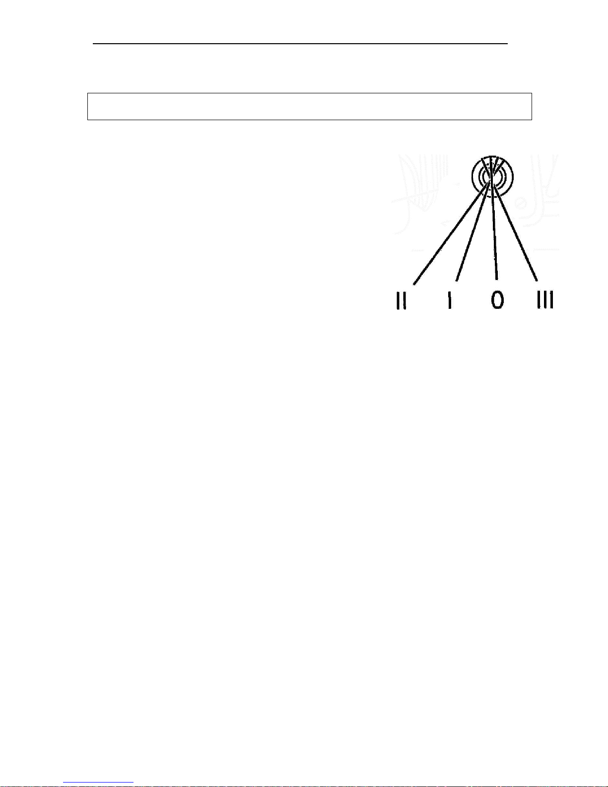
Starter and instrument switch
The switch (1) has four positions:
• 0 — OFF;
• I — Instruments ON;
• II — Starter ON (unfixed position);
• III — Radio ON (key turned counterclockwise).
31
Page 29
Section C. Controls and Instrumentation Belarus – 510/512 Operating manual
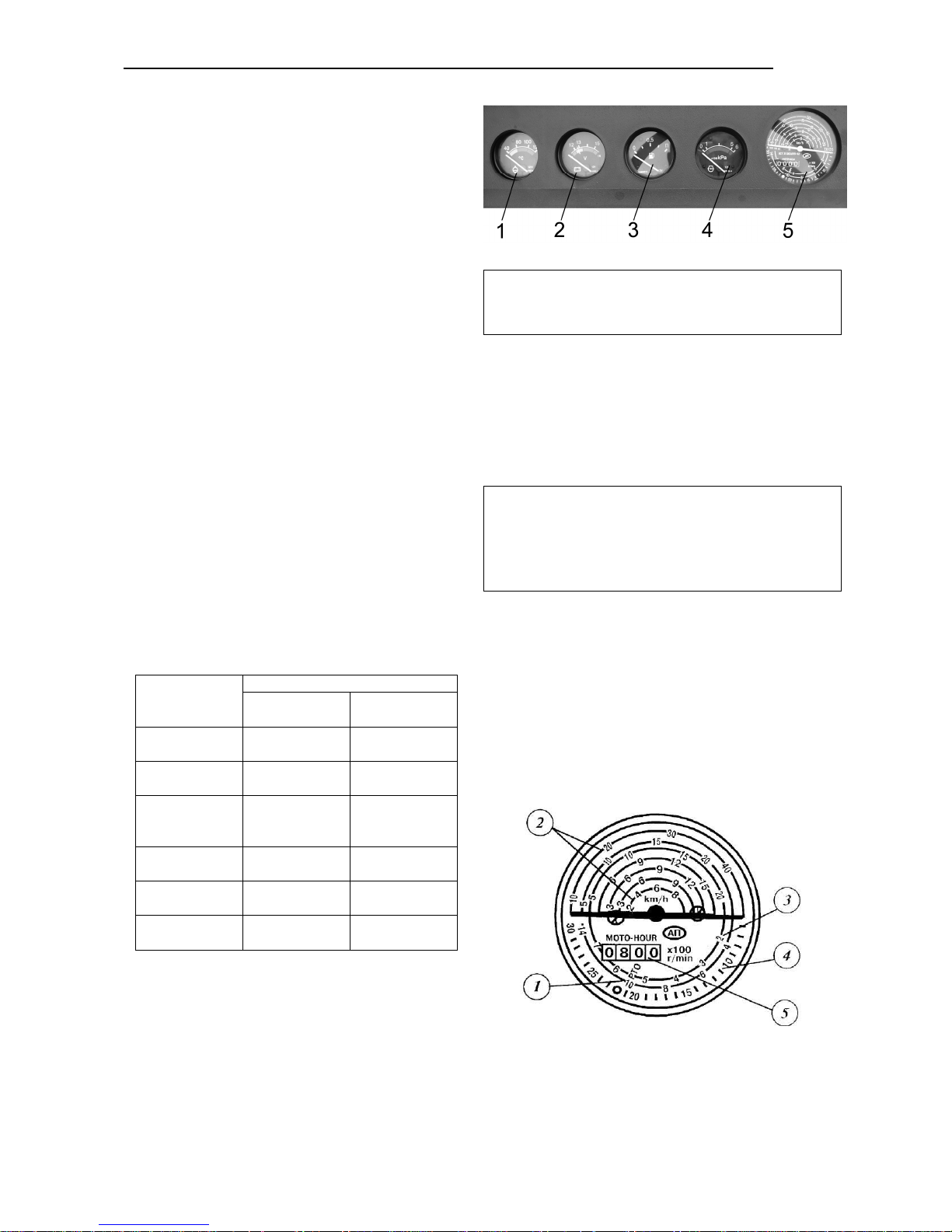
Autonomous instruments
Coolant temperature indicator (1)
The indicator (1) shows the engine coolant
temperature in degrees. The scale has
three zones:
- operating: 80 to 100°C - green;
- warning: 40 to 80°C - yellow;
- emergency: 100 to 120°C - red;
Fuel level indicator (3)
The indicator (3) shows the amount of fuel
in the tank. Do not let the fuel tanks to be
fully emptied in order to avoid ingress of air
to the fuel system.
The instrument has a mark-up:
0 - 0.5 – П
Voltage indicator (2)
The device indicates SB voltage on a dead
engine when the starter key (1) is in position “I”. When the engine is running, the
voltage indicator shows voltage in the tractor electric system.
Scale zone,
color
13.2 – 15.2 V
green
10.0 – 12.0 V
red
12.0 – 13.2 V
yellow
15.2 – 16.0 V
red
12.7 – 12.0
yellow
white hairline
in yellow zone
Feed system condition
when engine is
running
normal charging mode
generator not
operating
no SB charging
(low charging
voltage)
SB recharged
SB charging
SB rated EMF –
when engine is
off
battery discharged
SB has normal
charging
start
12.7 V
IMPORTANT! If the instrument shows no
SB charging, check the condition and tension of the fan driving belt.
Engine oil pressure indicator (4)
When the engine is running, monitor the instrument readings. The normal oil pressure is
1 to 5 kgf/cm² (green zone of scale). On a
cold engine, the pressure can rise to 6
kgf/cm².
IMPORTANT! Do not let the engine operate when the instrument readings are in the
red zones at the rated mode. If the oil pressure is too low or absent, immediately stop
the engine, find and correct the fault.
Tachometer/speedometer (5)
1. White background — tractor speed scale
(km/h) at II, III, IV GB ranges (5 to 16
gears).
2 and 3. Green background — rear inde-
pendent PTO speed scale (rpm);
4. Black background — engine speed
mode scale (rpm);
5. Engine service hours scale.
32
Page 30
Section C. Controls and Instrumentation Belarus – 510/512 Operating manual
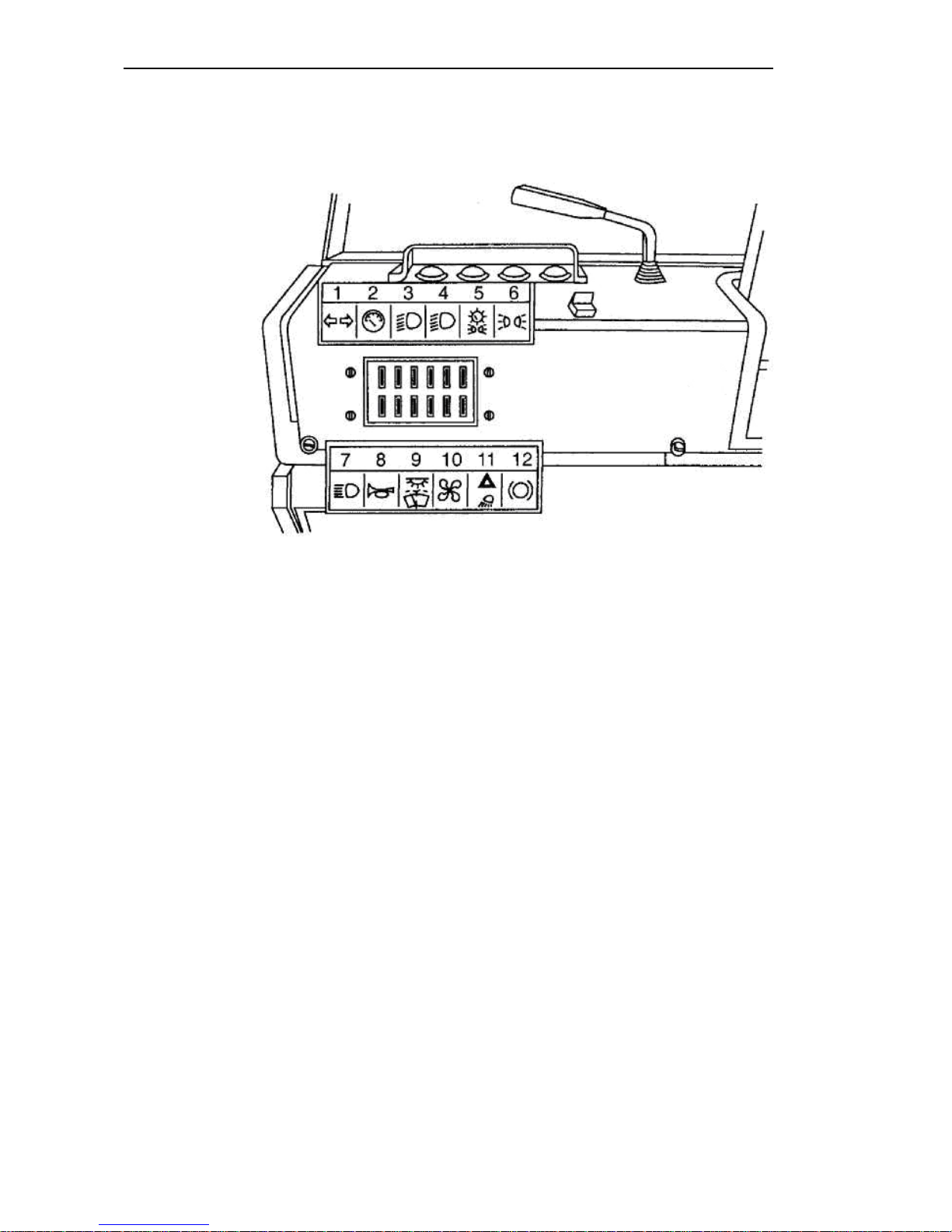
Fuses
In the instrument panel, two electric circuit fuses are mounted.
12 fuses protect the following tractor circuits from overloads:
1 — turn indicators, 15 A;
2 — instrumentation power, 7.5 A;
3 — left headlight lower beam, 7.5 A;
4 — right headlight lower beam, 7.5 A;
5 — right-side clearance lights, number plate illumination, instrument illumination, 15
A;
6 — left-side clearance lights, 7.5 A;
7 — headlight upper beam, 25 A;
8 — horn, 15 A;
9 — backup, 25 A;
10 — backup, 15 A;
11 — emergency stop signaling, rear working lights, 15 A;
12 — stop lights, portable lamp power, 15 A;
Besides, a block with a 60 A fuse is installed on the hydraulic system oil tank to protect
the SB charge circuits.
33
Page 31

Section C. Controls and Instrumentation Belarus – 510/512 Operating manual
Electric equipment connectors
A standard 7-pin socket is intended to
connect consumers of current of a transportation machine or attached implement. It is installed on the cab rear support. To the socket, the plug of the wire
harness of attached machines is connected.
Socket terminal designations:
1 — Left turn indicator;
2 — Horn
3 — Ground;
4 — Right turn indicator;
5 — Right clearance light;
6 — Stop signal;
7 — Left clearance light;
8 — Connection of portable lamp and
other consumers with a current load up to
8 A.
34
Page 32
Section C. Controls and Instrumentation Belarus – 510/512 Operating manual
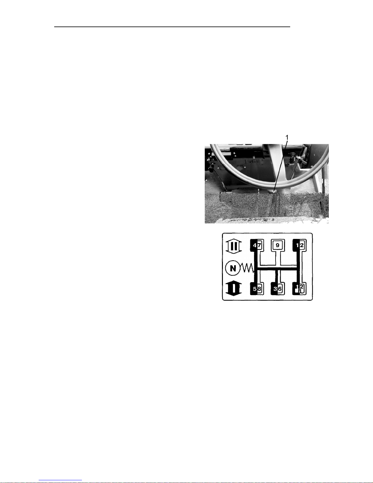
Gearbox control
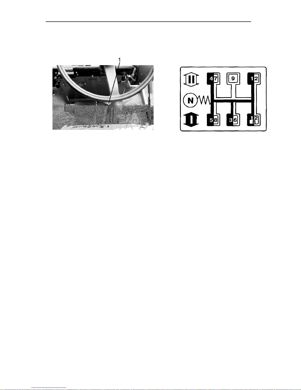
The gearbox is a 9/2 mechanical one.
The lever (1) shifts the gears as per the shift pattern. Before engaging a gear, engage
the required range (stage).
IMPORTANT! Ranges and gears are engaged by the same lever (1), a range is engaged first (Ist or IInd).
Attention! Use of the R gear in traction mode is not allowed.
35
Page 33
Section C. Controls and Instrumentation Belarus – 510/512 Operating manual
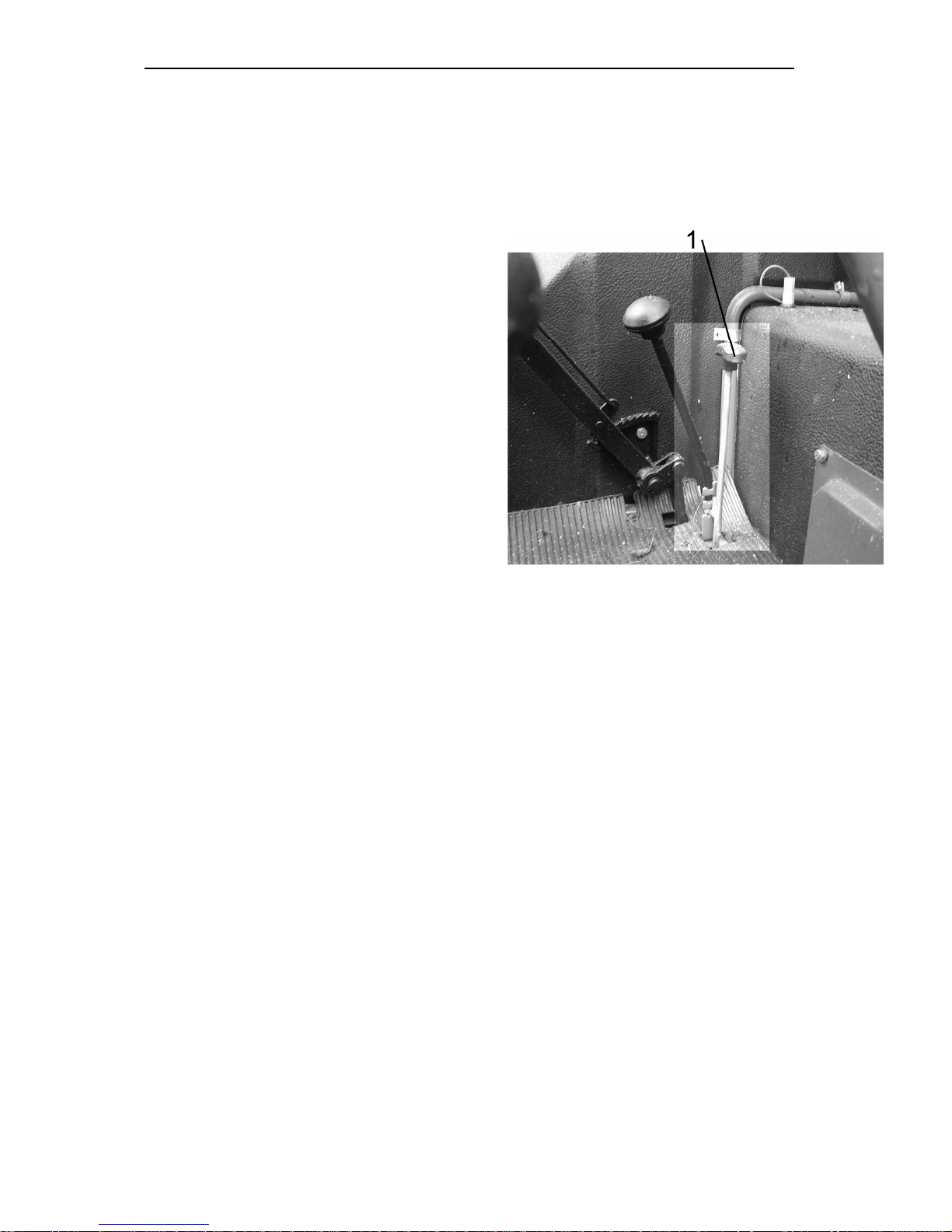
Front drive axle control
The control lever (1) has three fixed positions:
• FDA off — lowermost position. Use
on transport when moving on hard surface roads;
• FDA forcedly ON — uppermost position. Use this mode for a short time
when working on loose and wet soils
and, as necessary, during reverse
movement.
• FDA automatically ON (OFF) – mid position. In this mode, the FDA is engaged and disengaged automatically by the free running coupling depending on rear wheel skidding.
Use this mode for different field
works.
ATTENTION! When using the tractor
without driveshafts, shift the control
lever (1) to the uppermost position
(FDA forcedly ON).
36
Page 34
Section C. Controls and Instrumentation Belarus – 510/512 Operating manual
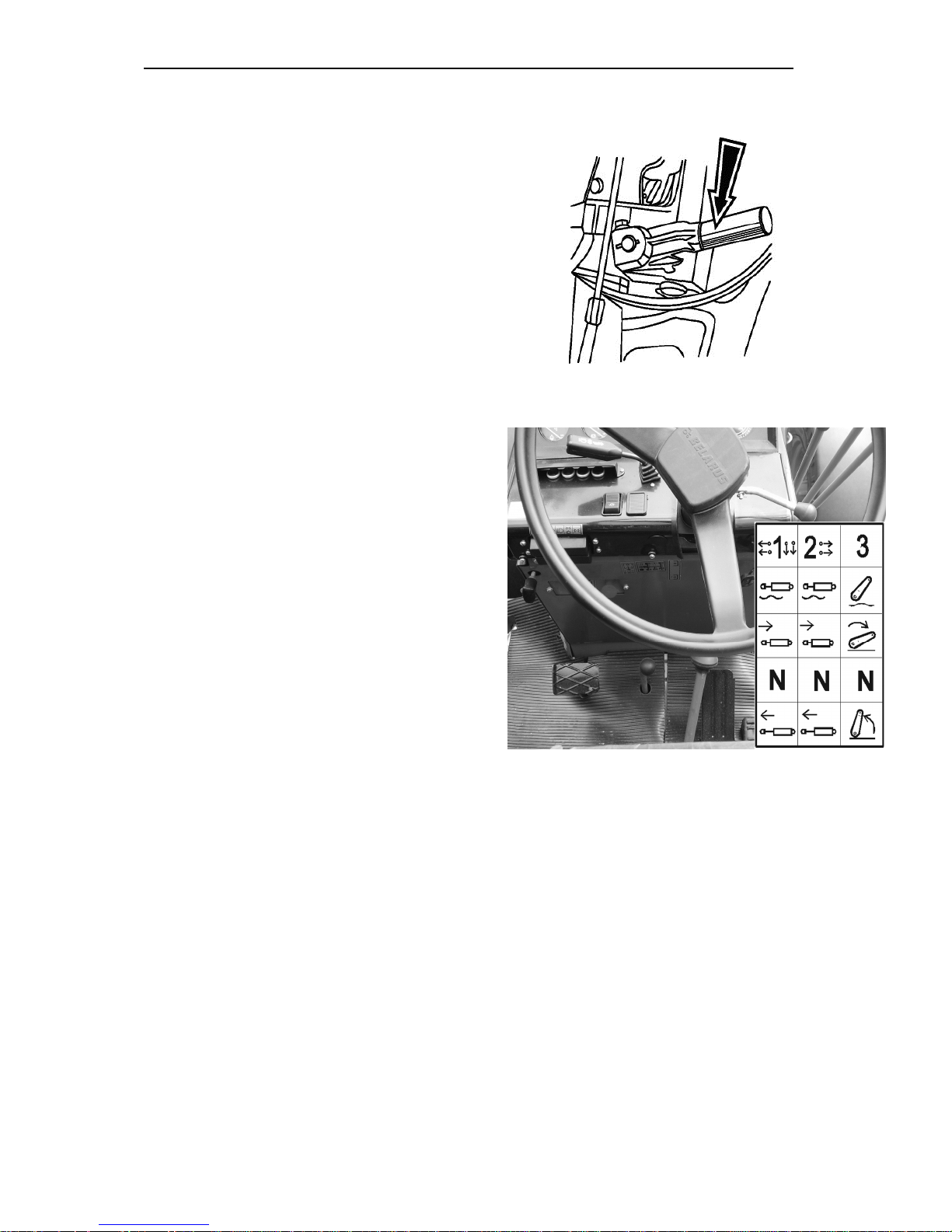
Hydraulic system pump control
The control lever has two positions:
• Pump ON — upper position;
• Pump OFF — lower position.
IMPORTANT! Turn on the pump only at
the engine minimum idle speed. Turn off
the pump for engine cold start or
maintenance.
Control of hydraulic system distributor
(external cylinder)
Each of the four levers controls the external cylinders and has four positions:
• Neutral — lower mid position (fixed);
• Lifting — lower non-fixed position.
When the cylinder rod reaches its extreme positions, the lever automatically returns to the Neutral position.
• Forced lowering — upper mid nonfixed position between the Floating
and Neutral positions. After lowering,
the lever automatically returns to the
Neutral position.
•
Floating — upper fixed position.
37
Page 35
Section C. Controls and Instrumentation Belarus – 510/512 Operating manual
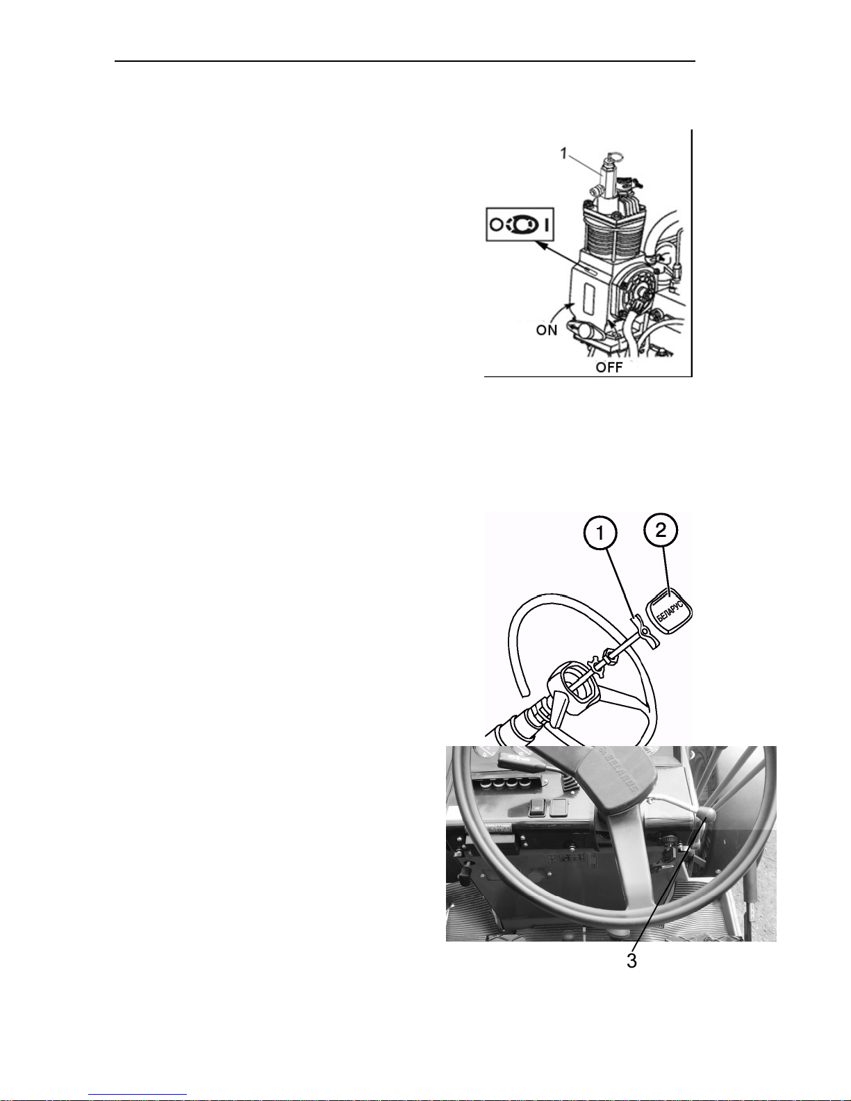
Compressor control
The handle has two positions:
• Compressor ON — when the handle is turned so that the arrow on
the arm would be directed backwards with respect to tractor motion;
• Compressor OFF — when the handle
is turned by 180°C so that the arrow
on the arm would be directed backwards with respect to tractor motion;
• The valve 1 screwed into the compressor is intended to take air to inflate tires as well as for other purposes
when energy of compressed air is required.
Changing steering wheel position
To change the position of the steering
wheel by height:
• Remove the cover (2);
• Unscrew the clamp (1) by 3…5 turns;
• Move the wheel to the desired position;
• Tighten up the clamp (1) by hand and
install the cover (2) to place.
NOTE: The range of steering wheel
adjustment by height is 100 mm.
To change inclination of the steering column, pull up the rod (3). The steering
column has four inclined fixed positions
from 25° to 40° with a step of 5°.
Seat
38
Page 36
Section C. Controls and Instrumentation Belarus – 510/512 Operating manual
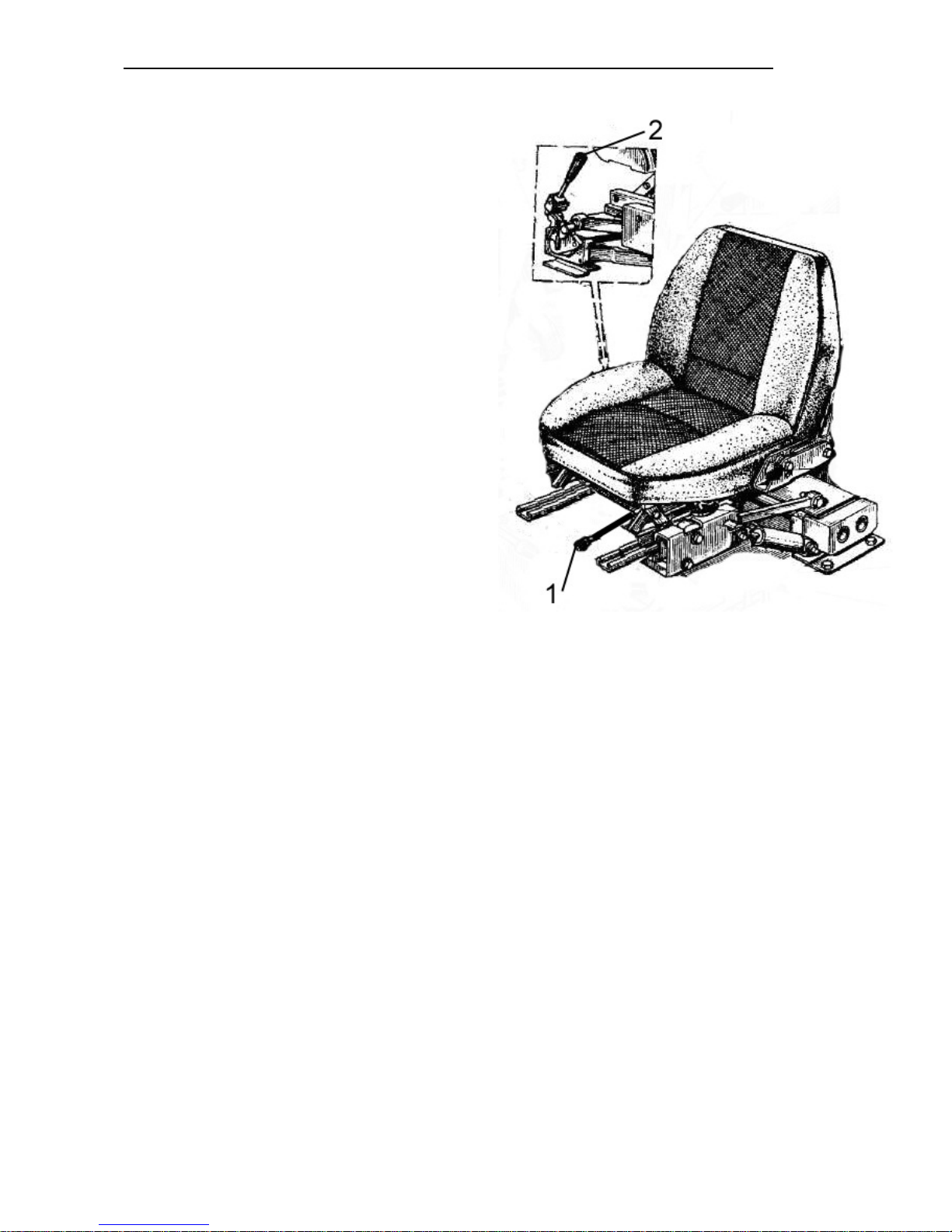
The driver’s seat is one-lace, cushioned
on a mechanical suspension with a hydraulic shock-absorber, is fixed to the
cab floow with four bolts. The seat can
be adjusted by driver’s weight from 60
to 120 kg, within ± 75 mm in the longitudinal horizontal plane. Correct adjustment of the seat by driver’s weight
greatly reduces vibration from the tractor. A correctly adjusted seat must go
down under driver’s weight by a half of
its travel (60 to 65 mm approximately).
Attention! After adjustments of the
seat, all handles (latches) must be returned to their initial positions.
1 — handle for seat longitudinal adjustment;
2 — handle for seat adjustment by
driver’s weight;
39
Page 37

Section D. Operating instructions Belarus – 510/512 Operating manual
Section D. OPERATING INSTRUCTIONS
Tractor pre-operation
When preparing a new tractor for operation, depreserve it proceeding as follows:
• remove protective covers and plugs
fitted on the engine;
• install peacocks of the radiator and cylinder block;
• fill in all the refill tanks;
• unpack the muffler put in the cab and install it onto the exhaust manifold so that
exhaust pipe outlet cut would be directed
forward along the tractor motion. Install the
retaining clip at a distance of 8 to 12 mm
from the muffler pipe end. Tighten the clip
nuts to a torque of 44 to 54 Nm;
• drain sediment from the coarse and fine
fuel filters and fuel tank;
• fill the fuel supply system with fuel and
bleed the system to remove air from it;
• check the fan belt tension;
• check and adjust the air pressure in the
tires;
• perform servicing of the storage battery;
• tighten the fasteners;
• grease all the lubrication points using a
gun;
• check and adjust, if necessary, the
front wheel toe-in.
WARNING! To avoid injuries, make
sure that all protective guards are in
their places prior to starting the diesel
engine.
ATTENTION! Starting a new engine,
which is not run-in, by towing is not allowed to avoid the intense wear of the
engine parts.
Running-in
Your new tractor will work reliably and
for long time, provided that running-in is
made properly and necessary maintenance is provided within the recommended terms. When executing the 30hour running-in, observe the following
rules:
1. Constantly monitor the instrument
readings and operation of the lubricating, cooling and feed systems.
Monitor the oil and fluid levels in refill
tanks.
2. Check tightening and retighten the
external fastening junctions.
3. Run in the tractor on light transport
and field works (harrowing, cultivation, sowing, etc.), gradually increasing the load at different gears.
4. Do not overload the engine, do not
allow fuming or drop of the rotational
speed. The overload symptoms are
abrupt drop of the engine speed,
fuming and failure to respond to
higher fuel feed.
5. The operation of the tractor at very low
gear with small load at high engine
speeds will result in excessive fuel
consumption. Correct selection of a
gear for each particular work provides
fuel saving and reduces engine wear.
6. Regularly perform time-shift maintenance in accordance with recommendations stated in this Manual.
7.
After running-in the tractor, perform
the maintenance works.
40
Page 38

Section D. Operating instructions Belarus – 510/512 Operating manual
Starting engine
Starting under normal conditions:
IMPORTANT! Start the engine and check the
Check the oil level in the engine crankcase and the coolant
instrument operation while sitting in the operator’s seat only.
level in the radiator, as well as
fuel in the tank.
IMPORTANT! Never start the
engine with an empty cooling
system!
Warning: Never operate the tractor indoors.
1. Engage the parking brake (1);
2. Switch on the ground switch;
3. Shift the fuel feed lever to the middle
position;
4. Shift the PTO control lever to the OFF
position;
5. Step on the clutch pedal;
6. Shift the gear shifter lever to its neutral
position, shift and hold it in the leftmost positions.
7. Turn the starter key to the position II
(Start) and hold it until the engine
starts, but not more than 15 s. If the
engine fails to start, repeat starting after at least 30 to 40 s.
8. After the engine starts, release the
clutch pedal and the gear shifter lever.
Check the operation of all indicating
lamps and instrument readings (coolant temperature, oil pressure in the
engine and storage battery charge).
9. Let the engine run at 1,000 rpm until
the oil pressure stabilizes in the operating range.
41
Page 39

Section D. Operating instructions Belarus – 510/512 Operating manual
42
Important!
War
n
ing:
IMPORTANT!
Note
:
Starting at low temperatures (+4°С
and below)
To avoid damage of the
power gear, do not push or pull the
tractor to start the engine by towing.
Never use ether means to aid engine
start with an electric torch pre-heater
installed. Application of ether can result in an explosion of the intake manifold and severe injuries.
When low temperatures are
steady, use winter-grade oils in the
engine crankcase, gearbox and hydraulic system according to the recommendations in this Manual.
Keep the batteries fully charged.
Use clean, without water wintergrade diesel fuel.
To avoid failures, every day drain
sediment from the coarse fuel filter
and fuel tanks.
Refill the fuel tanks at
the end of each working day to prevent condensation in the tanks.
When starting the engine at low
temperatures, a circulation pre-heater
can be used for a cooling system
filled with antifreeze agent. Contact
your dealer for more details on preheater installation.
Procedure of starting the engine at
low temperatures:
1. Turn off the drive of the hydraulic
system oil pump to reduce resistance to crankshaft rotation.
2. Perform the actions 1 to 9 as indi-
cated in the Section “Start under
normal conditions”.
Page 40
Section D. Operating instructions Belarus – 510/512 Operating manual
43
Getting tractor moving
ATTENTION! When selecting the re-
quired gear, use the gear shift pattern.
To start the movement, proceed as follows:
• engage the required gear as per the
gear shift pattern;
• step on the clutch pedal;
• in the neutral position shift the gear
shifter lever (1) to the leftmost position and set the range II or I respectively by moving the lever forward or
backward;
• return the lever to the neutral position
and then set the required speed by
moving the lever (1) forward or backward as per the pattern;
Release the parking brake and release smoothly the clutch pedal while
increasing slightly the fuel feed. After
starting the motion, increase the fuel
feed.
Avoid getting moved with a high traction
load (e.g. a plough deepened into the
soil).
ATTENTION! Always step on the
clutch pedal prior to engaging the
range (step) and a gear.
Do not hold the foot on the clutch pedal during operation on the tractor,
since this can lead to clutch slipping,
its overheating and failure.
Page 41

Section D. Operating instructions Belarus – 510/512 Operating manual
44
Stopping tractor
To stop the tractor:
• reduce the engine crankshaft speed;
• use the service brakes to stop the
tractor;
• step on the clutch pedal;
• shift the gear shifter lever to the neutral position;
• engage the parking brake.
Steering
IMPORTANT! The tractors are
equipped with the hydrostatic steering
booster. If the engine is stopped, the
pump does not supply the system and
it starts automatically operating in the
manual mode where turning the tractor
requires a greater force to be applied
to the steering wheel.
IMPORTANT! To stop the tractor in
case of emergency, step on the clutch
pedal and twinned service brakes pedal at the same time.
Shutting down engine
IMPORTANT! Prior to shutting down
the engine, lower the implement onto
the ground and let the engine operate
at 1,000 rpm for 1 to 2 min. This will
decrease the engine temperature.
To shut down the engine, proceed as follows:
• set manual fuel feed lever to minimal
feed position (back to the stop);
• disengage the PTO and shift all distributor levers to their neutral positions;
• lower the implement onto the ground;
• pull engine shut-off lever cord handle to
fully stop the engine;
• turn off the ground switch to avoid storage
battery run-down.
Hydraulic system
The hydraulic system controlling the threepoint rear attachment ensures system operation in the height control mode.
Height control
When working with attached tillers, they
must have a supporting wheel.
Page 42
Section E. Unitizing Belarus-510/512 — Operating manual
45
Section E. UNITIZING
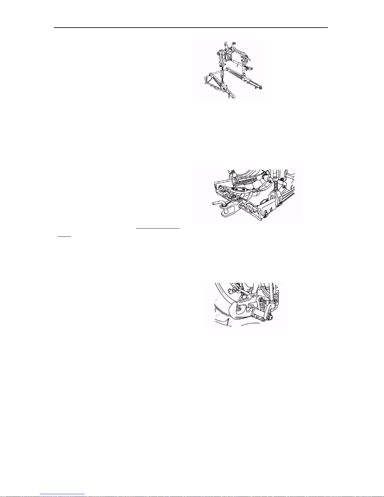
Working equipment for attaching agricultural machines to the
tractor
(for tractors with power regulator)
Rear three-point hitch linkage — to attach mounted and semi-mounted machines such as plows, seeders, cultivators, spraying machines etc.
Haul-and-draw coupler (cross-piece)
ТСУ-1Ж — to work with trailed ma-
chines, potato harvesters etc. (except for
one-axle trailers) with a speed of up to 15
km/h.
ATTENTION! Use of ТСУ-1Ж for
transportation works is strictly forbidden!
Haul-and-draw coupler ТСУ-2 (hydraulic
hook) — for operation with one-axle trailers
and other machines.
45
Page 43
Section E. Unitizing Belarus-510/512 — Operating manual
885 or 805
mm
Rear hitch linkage
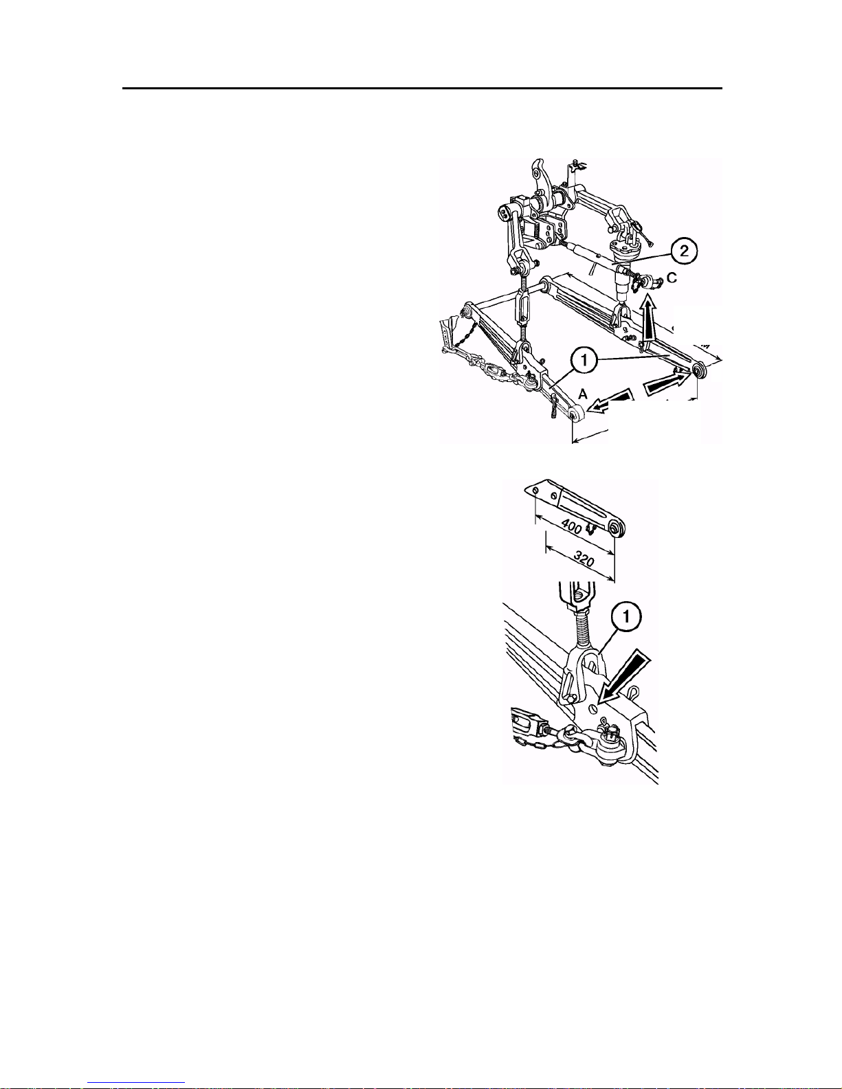
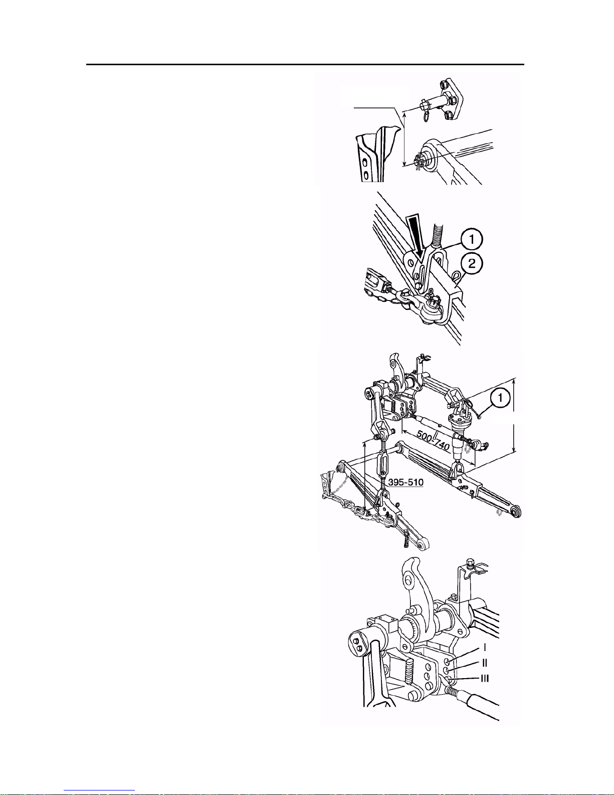
The three-point rear hitch linkage of category 2 ensures attaching mounted and
semi-mounted agricultural machines and
implements to the tractor with the following connecting pieces:
• length of suspension axis L (distance
between the joints A and C) is 870 mm;
• height of machine post is 510 mm; 610
mm
• diameters of fingers for connection to
the lower rod joints (1) is 28.7 mm;
• diameter of finger for connection to the
upper rod (2) is 25 mm.
В
ATTENTION! Before connecting machines, carefully read this section.
The lower rods consist of two parts:
• the front part or the rod itself;
• the back end with a ball joint. Rated
length of lower rods is 885 mm.
To increase the suspension length, set
the rod ends with the bent front joints
(F70-4605050-01/055-01).
To increase the carrying capacity of the
suspension, replace the rod back ends
(400 mm length) with rod ends with a distance between the joint axle and the front
hole of 320 mm (N50-4605040А2/045А2).
The total length of the lower rod becomes
805 mm.
ATTENTION! With the rod length of 805
mm the carrying capacity of the suspension increases by 10% with a simultaneous decrease of the lift height by 10%.
The same increase in the carrying capacity can be achieved by installing the brace
(1) to additional points (the lift height also
decreases by 10%).
L = 870 mm
46
Page 44
Section E. Unitizing Belarus-510/512 — Operating manual
425-520
To inscrease the road clearance when processing long-stalk crops, install the front
ends of the lower rods to additional suspension axles located by 110 mm above the
lower rod axle. To copy the floor profile in
the transverse direction while working with
wide-cut implements, link the braces (1)
with the lower rods (2) through the longitudinal grooves.
IMPORTANT! The brace forks must be
behind the hole to avoid damage to the
brace.
Upper rod and braces
The upper rod length can be adjusted from
500 to 740 mm. The length of the adjustable right brace can be adjusted from 425 to
520 mm by turning the handle (1). When
shipped from the factory, the right brace
length is set to the standard value of 475
mm. The length of the right (unadjustable)
brace is also set to the standard value of
475 mm when the tractor is shipped from
the factory.
During operation, the left brace length can
be changed from 395 to 510 mm depending on the tractor delivery set and kind of
attached machines and equipment.
110 mm
IMPORTANT! Adjust an implement in
the transverse plane only with the right
brace.
Depending on the plowing depth and soil
nature, set the upper rod in one of the three
positions:
I — light soils and small plowing depth at
power control;
II — medium soils and medium plowing
depth at power control;
III — heavy soils at a bid plowing depth, as
well as at position control or without use of
power regulator.
47
Page 45
Section E. Unitizing Belarus-510/512 — Operating manual
Mounting machines to the tractor
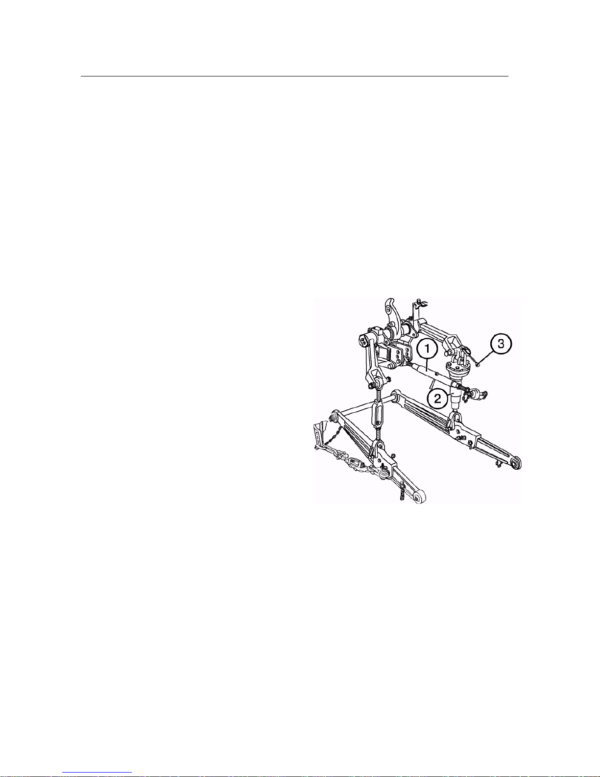
1. When mounting machines to the tractor,
first make sure that no one is present in
the zone of mounting the machine.
2. Using the handle of the power regulator (if
available), lower the suspension to the
lower position, drive the tractor back and
attach the machine to the lower rods.
Splint the fingers. Stop the engine.
3. Lengthen or shorten the upper rod (1) and
link the rod ball joint to the machine. Splint
the finger.
4. If necessary, adjust the upper rod to the
initial or desired length.
5. If necessary, adjust the transverse tilt
of the machine using the right adjustable brace (2). To increase the brace
length, turn the lever (3) clockwise and
vice versa.
6. Before you start working, make sure that:
• the tractor don't be in dangerous prox-
imity to the machine elements;
• the upper rod do not touch the PTO
guard at the lowermost position of the
machine;
• the PTO cardan drive be not too long,
with large joint angles, and that there be
no thrust forces;
• the PTO guard do not touch the ma-
chine cardan drive guard.
7. Slowly lift the machine and check availability of clearances of 100 mm min. between the wheel and the machine in the
raised position.
8. Check availability of the required side
oscillation of the lower rods and, as necessary, adjust with the braces.
48
Page 46
Section E. Unitizing Belarus-510/512 — Operating manual
Attach machines (implements) to the tractor also using the automatic coupling СА-1,
connected to the hitch linkage of the tractor
in three points (two rear joints of the lower
rods and the rear joint of the upper rod).
To prevent spontaneous disconnection of
the machine from the tractor, fix the latch of
the automatic coupling with a spring catch
pin.
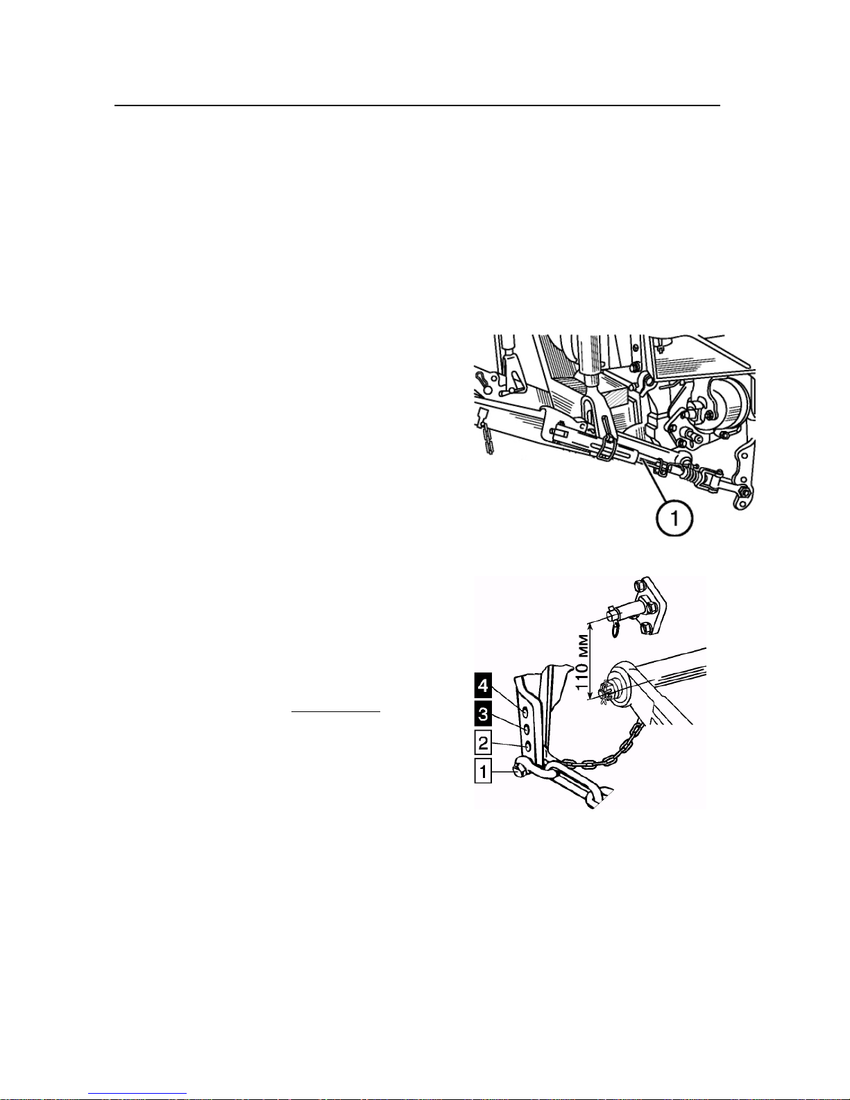
Limit (telescopic) rods (1)
The rods are used to limit side oscillation of
the suspension lower rods both in the
transportation, and in the working position.
This is especially necessary when working
on slopes, close to ditches, walls etc.
The back end of the rod is connected to
the lower rod, and the front end is connected to the bracket in one of the four
positions depending on the job.
• Position 1. The rods prevent side oscillation of the implement in the transportation position.
• Position 2. The rods prevent side oscillation of the implement both in the transportation and in working positions.
IMPORTANT! Use the positions 3 and 4
only when installing the lower rods to additional suspension axles (upper axles).
• Position 3. The rods prevent side oscillation of the implement in the transportation position.
• Position 4. The rods prevent side oscillation of the implement both in the
transportation and in working positions.
ATTENTION! The rods must be installed only to the bracket holes that
are second from the bottom (position 2)
to prevent damage to the rods.
ATTENTION! The rods must be installed only to the bracket holes that
are second from the bottom (position 2)
to prevent damage to the rods.
49
Page 47
Section E. Unitizing Belarus-510/512 — Operating manual
Partial lock of telescopic rods
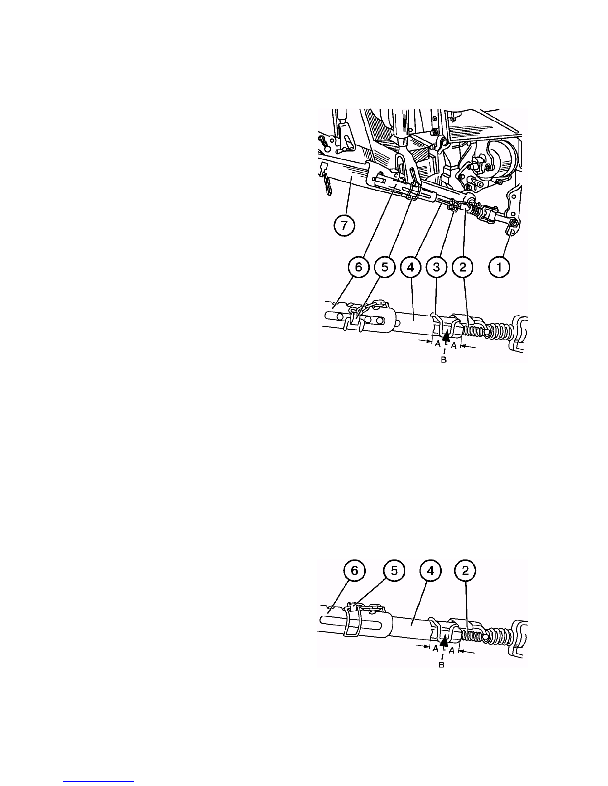
ATTENTION! The telescopic rods must be
installed only to the hole that is second
from the bottom.
To ensure the desired side movement of
the machine, ex. plow, in the working position, adjust the rods as follows:
• turning the screw (2), set the handle (3) to
the middle of the flat “B”;
• remove the cotter (5) from the rod;
• attach the machine to the lower rods (7)
and lift it off the ground;
• aligning the hole in the inner pipe (4)
with the groove of the pipe (6), insert the
cotter (5) in the middle of the groove.
IMPORTANT! Install the cotter (5) so
that it be in the middle of the groove or
slightly closer to the tractor. Otherwise
the rods may be damaged.
Before a transportation journey, raise the
machine to the upper position and check
its side oscillation that must not exceed
20 mm to any side. If necessary, adjust
the oscillation magnitude turning the screw
(2).
Fully locking rods
To fully lock machines, ex. a cultivator or a
trailed device, in the working position adjust the rods similarly to the partial lock,
except for the last operation, at which align
the hole of the inner pipe (4) with the hole
of the outer pipe (6) and insert the cotter
(5) into the holes.
Ensure a full lock in the transportation position (with the machine lifted) by screwing
the screw (2) into the pipe (4) to the maximum extent possible.
50
Page 48
Section E. Unitizing Belarus-510/512 — Operating manual
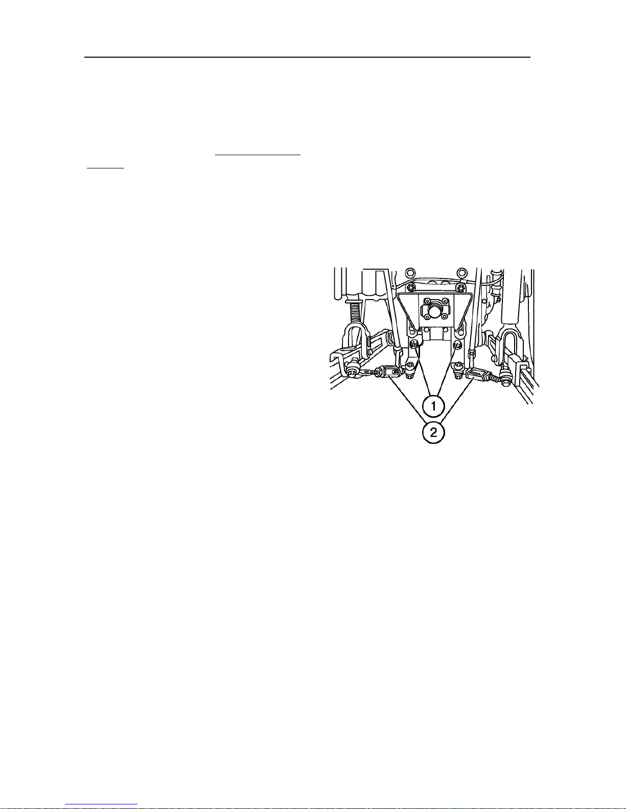
Inner rods (2)
Used also to limit side oscillation of machines both in the working and in transportation positions.
NOTE: The telescopic rods are installed only
outside.
Partial lock (for plowing)
Adjust at the machine working position as
follows:
• screw the adjustment bolts (1) into the
brackets up to stop;
• lift the machine so that its tools take off the
ground;
• adjust the right bracket length to the desired plowing depth (when working with
a plow);
• by rotating the braces (2), adjust the length
of the limit chains ensuring machine
movement in the horizontal plane by 125
mm to each side from the middle position
or according to the machine operating
manual.
When installing the machine to the transportation position, screw out the bolts (1)
for its partial lock. Oscillation of the machine to the both sides to 20 mm max. is
allowed.
A full lock (for cultivation, sowing etc.) is
set as follows:
• fully screw in the adjustment bolts (1);
• shorten the rods (2) to the maximum extent possible.
IMPORTANT! When changing the right
brace length, always re-adjust the rods.
51
Page 49
Section E. Unitizing Belarus-510/512 — Operating manual
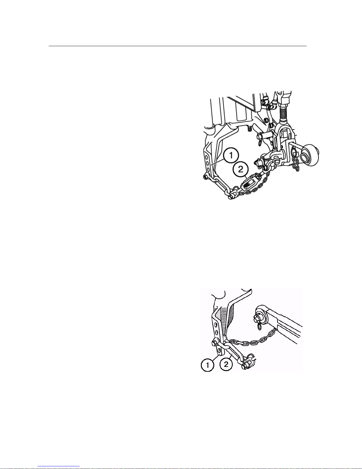
Outer chain binders (2)
Partial lock
Ensure horizontal movement of the machine in the working position by connecting the limit chains to the lower holes of
the brackets (1) and adjusting the chain
length using the rods (2), to obtain oscillation of the tool to each side by 125 mm
min. or according to the machine operating
manual.
When working with plows, adjust the right
bracket length to the desired plowing depth.
ATTENTION! Always maintain the oscillation of the machine of 125 mm min. to
avoid break of chains when the machine
is lifted to the transportation position.
When installing the machine to the transportation position, tension the chains with
the rods (2). Oscillation of the machine of
20 mm max. to the both sides is allowed.
Full lock
To fully lock the machine in the transportation position, attach the limit chains (2) to
the hole of the bracket (1) second from the
bottom and shorten the chains (2) to the
maximum extent possible.
In the transportation position, lock is provided automatically.
52
Page 50
Section E. Unitizing Belarus-510/512 — Operating manual
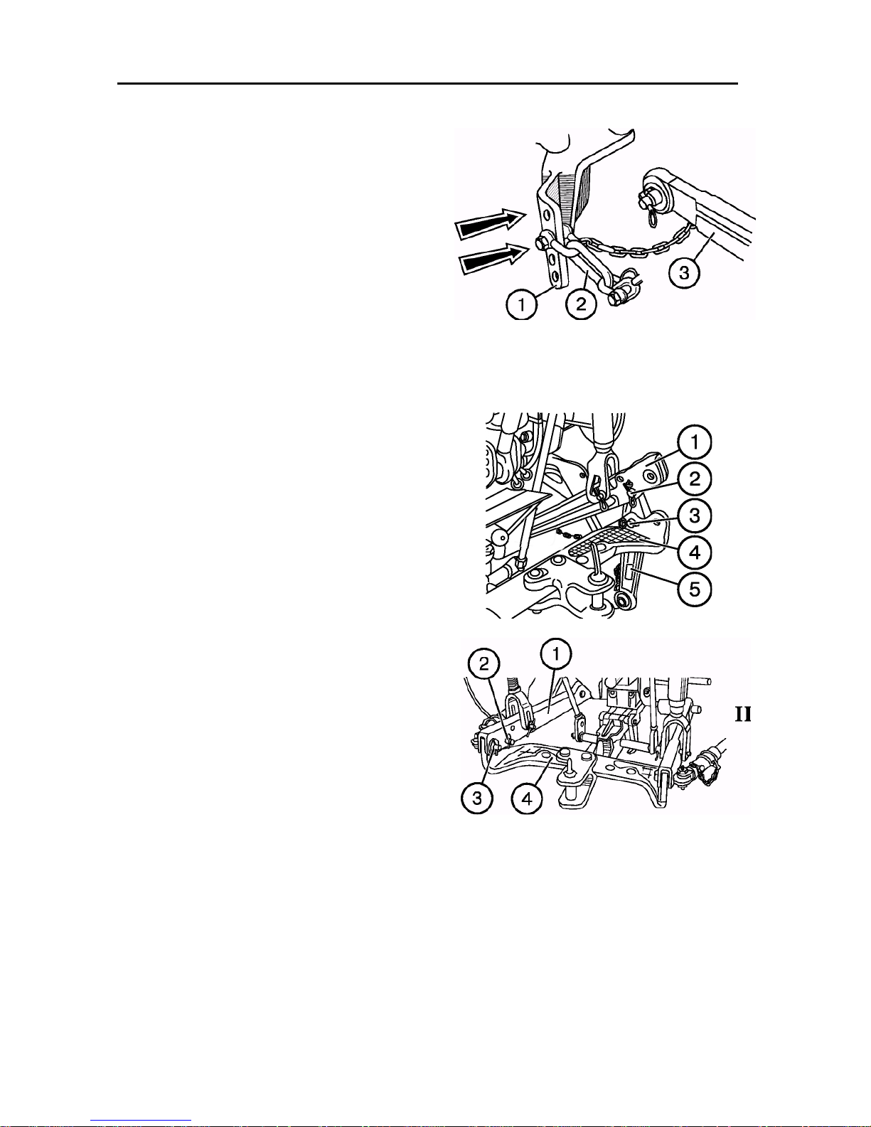
Additional suspension axles of
lower rods of hitch mechanism
When processing high-stalk crops, install
the lower rods (3) to additional suspension
axles. At that, to partially lock the machine
in the working position, attach the limit
chains (2) to the hole of the bracket (1)
third from the bottom and to fully lock — to
the fourth hole.
In the transportation position, lock is provided automatically.
Haul-and-draw coupler ТСУ-1Ж (crosspiece) (4)
The haul-and-draw coupler is used to attach machines working at speeds not exceeding 15 km/h/ Tractors are shipped
from the factory with the cross-piece installed as shown in Fig. I. To re-set from
the transportation position (I) to the working
position (II), proceed as follows:
1. Unsplint and take out the eye (3), remove the cross-piece (4).
2. Unsplint and take out the finger (2), remove the back ends of the lower rods (5).
3. Install the cross-piece (4) to the front
ends of the lower rods (1), fasten it with
the eye (3) of the limit chains, fingers (2)
and splints (see Fig. II).
With outer or inner installation of limit chains,
ensure a full lock of the haul-and-draw coupler. When installing a haul-and-draw coupler
with telescopic rods, attach them to the bracket
hole second from the bottom and ensure a full
lock.
ATTENTION! It is forbidden to use the
haul-and-draw coupler forks to work with
trailers at a speed exceeding 15 km/h.
IMPORTANT! Make sure that the hauland-draw coupler is locked from side oscillation by adjusting the inner or outer
rods.
IMPORTANT! Make sure that the hauland-draw coupler is locked from side oscillation by adjusting the inner or outer
rods.
53
Page 51
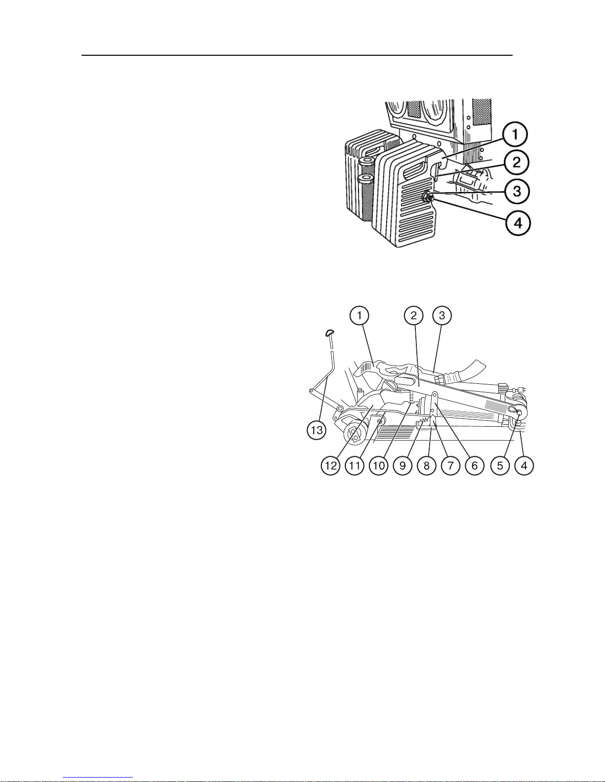
Section E. Unitizing Belarus-510/512 — Operating manual
Mechanism of locking an attachment of a tractor
with a small cab:
cylinder
—
pivot lever;
Front counterweights.
When working with heavy implements and
tools, to preserve normal controlability of
the tractor under conditions of significant
unloading of the front axle, install additional counterweights (1) (10 pcs. 20 kg
each). The counterweights are installed on
the special bracket (2) attached to the front
bar of the tractor and braced with the
string (4) and nut (3).
Mechanism of locking attachment in transportation position
a) lift the attachment to the uppermost
position, shifting the distributor lever
to the lift position.
The stop 10 of the cylinder hydromechanical valve must be in the rearmost
position on the cylinder rod.
b) bring the handle 13 and the lock
mechanism with it to the lower position;
c) shift the distributor handle to the float-
ing position. Under action of the attachment, the pivot lever 12 turns,
and the tooth must engage with the
catch 1.
To unlock the attachment, proceed as
follows:
a) lift the attachment to the uppermost
1 — catch; 2, 3 — rods; 4 —
brackes; 5 — axle; 6, 7 — levers; 8 — bracket; 9
spring; 10 — stop; 11 — control rod; 12 —
13 — control handle.
position, shifting the distributor lever
to the lift position.
b) lift the handle 13 to the upper position.
54
Page 52
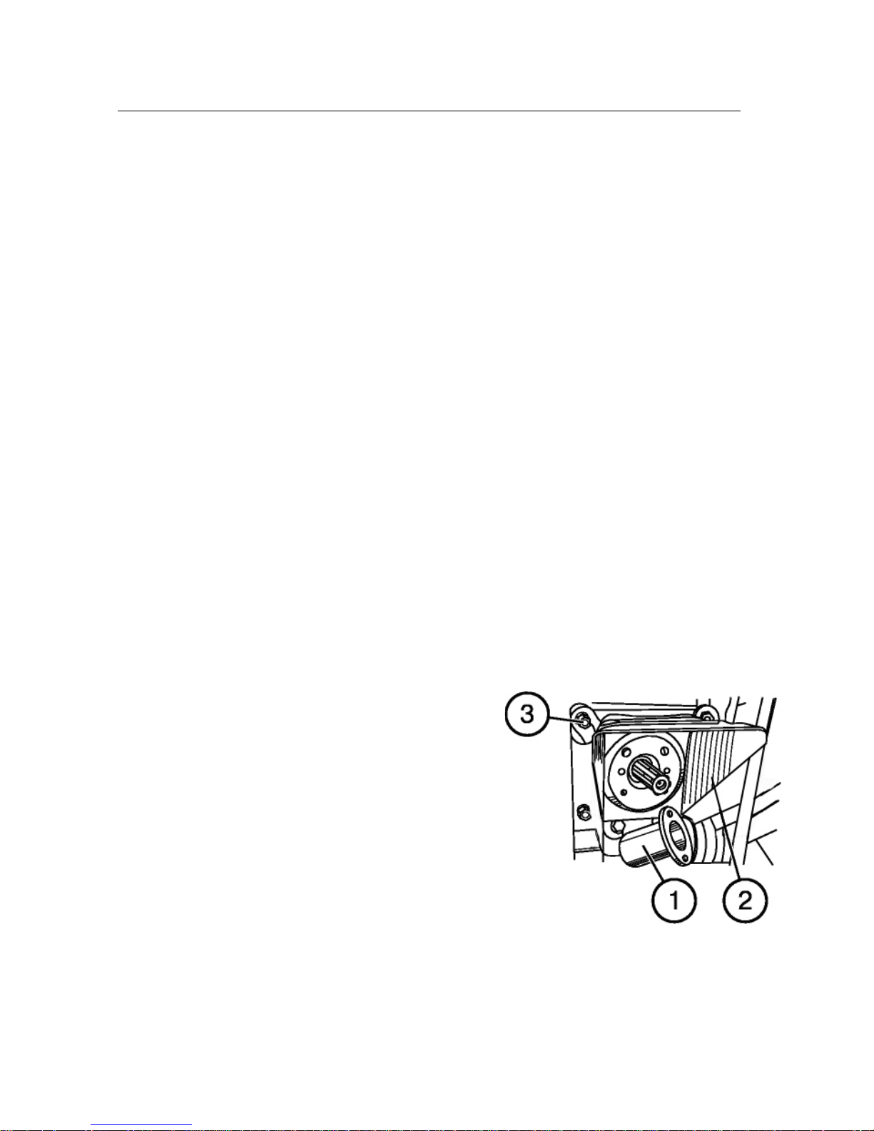
Section E. Unitizing Belarus-510/512 — Operating manual
Control of hydraulic system and
hitch linkage of tractor
On tractors, the hitch linkage is controlled
by the extreme right lever of the distributor.
Working with implements, use only the lift
and floating positions of the lever.
It is forbidden to shift the lever to the
lowering position when working with
soil processing implements!
Use the lowering position only to control
the extension cylinders installed on a machine and intended to control positions of
tools (such as reel, haeder, sharers etc.) of
harvesting, sowing and other machines. If
after completion of a cylinder stroke, the
distributor lever does not return to the neutral position automatically, bring it there
manually. And on the contrary, in case of
an early return of the lever, hold it with
hand to let the operation be completed.
Specifics of operating tractor with
machines requirind drive from rear
PTO
General recommendations:
a) before attaching a machine, make sure
that the PTO control is correctly adjusted;
b) install and secure the required (6-, 8- or
21-spline) PTO shank and engage the
respective speed drive, at that set 540
rpm for the 6-, 8-spline one and 1,000
rpm for the 21-spline one.
To replace the PTO shank, proceed as
follows:
1. Unscrew four bolts and remove the cap (1).
2. Unscrew the four nuts (3) and remove
the casing (2).
55
Page 53
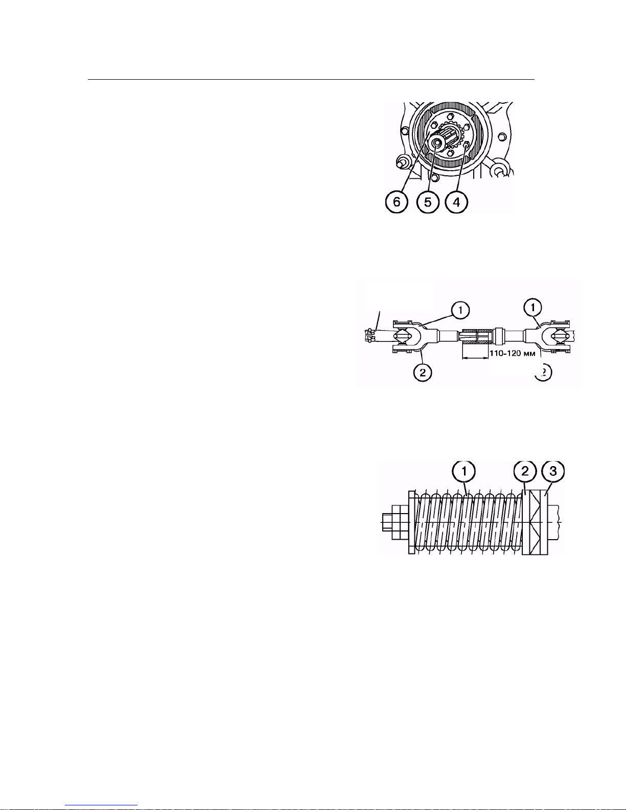
Section E. Unitizing Belarus-510/512 — Operating manual
3. Unscrew the six bolts (4), remove the
lock plate (6) and remove the shank
(5).
4. Install another shank into the spline hole
and install the plate (6), screwing in the
bolts (4) to a torque of 50 Nm.
5. Assemble the other parts in the order
reverse to disassembling.
c) lubricate the shaft and pipe of the tel-
escopic joint of the cardan drive with
solid oil. Install the cardan drive joint
to the PTO shank, secure it in the fix-
ing groove. Make sure that the forks
(1) of the joints of intermediate (tele-
scopic) shaft lay with the ears (2) in
the same plane. Failure to observe
this requirement results in overloads
of the cardan drive and PTO.
d) install the casing of the agricultural
Tractor PTO
end
machine driveshaft;
e) after installing the cardan drive, make
sure, that the elements of the cardan
drive telescopic joint do not stop against
the tractor in the extreme positions of the
110-120 mm
machine; the minimum overlap of the
cardan drive telescopic part must be 110
to 120 mm as in case of a lesser value
the drive may disengage.
f) adjust the safety coupling of the agri-
cultural machine by changing the
length of the spring (1). It must be ad-
justed so that in case of overloads the
cam clutches 2 and 3 rotate each rela-
tive to the other. A too strong tension
of the spring results in maloperation of
the clutch and overloads of the cardan
drive and PTO.
g) engage the PTO independent drive at
minimum engine speed or when the
engine is off. Engage the synchronous
PTO drive when the engine is running
by gradually engaging the clutch.
h) disengage the PTO when making
turns with the machine (for trailer ma-
chines) as well as when lifting the ma-
chine to the transportation position (for
mounted and semi-mounted ma-
chines);
56
Page 54

Section E. Unitizing Belarus-510/512 — Operating manual
i) after detaching the machine from the
tractor do not leave the cardan drive
joint on the PTO shank;
j) when installing the drive pulley on the
PTO rear cover, as well as drive re-
duction gears of the special machine
drive (cotton-growing, excavating ma-
chines etc.), make sure that they be
centered relative to the shank (fit into
the bore Ø162 mm on the rear cov-
er), and their fastening nuts are tight-
ened up securely.
When working with rotation machines
for tilling:
a) monitor serviceability and normal op-
eration of safety devices;
b) do not engage the PTO with a tool put
down to the ground;
c) bring down the machine with rotating
tools smoothly during tractor movement;
d) do not engage the PTO when the refrac-
tion angle in one of the cardan drive
joints exceeds 22 degrees;
e) when working on hard soils, process
transverse strips to enter the enclo-
sure, only then work the field in the
longitudinal direction.
ATTENTION!
When operating the tractor without use
of the PTO, always shift the PTO control
lever to the PTO ON position, set the
shift clutch of the PTO two-speed drive
to the position 1 (540 rpm), and set the
shifter lever from the independent to the
synchronous PTO drive to the middle
(neutral) position.
When the PTO synchronous drive is engaged, do not drive faster than 8 km/h.
At a speed higher than specified, rotation of the PTO parts exceeds the allowable values, which results in early failures of the unit.
Working with mounted and semimounted machines
piece) is allowed only at a speed not exceeding 15 km/h without driving on public
roads and when performing agricultural
works.
ATTENTION!
Attaching machines such as trailers and
semi-trailers through ТСУ-1Ж (cross-
piece) is strictly forbidden.
When working with single-axle trailers,
install additional counterweights to add
additional load to the tractor front axle.
When a towing gear is installed on the tractor, do not attach semi-trailers (single-axle
trailers) as well as non-standard towbars.
Single-axle machines such as semitrailers are attached to the tractor by
ТСУ-2 (hydraulic hook). Transportation
of the machines using ТСУ-1Ж (cross-
57
Page 55

Section E. Unitizing Belarus-510/512 — Operating manual
Use of rear attachment with a tow gear
installed on the tractor is strictly forbidden!
The trailers work at speeds determined
by road conditions. With 2ПТС-4-887А
with 20 and 45 m³ bodies, operating at
speeds up to 15 km/h is allowed, as they
have lower stability. Avoid making sharp
turns for such trailers and 1РМГ-4
spreaders to avoid damages to rear
fenders.
The hinge of trailers (2ПТС-4-785А etc.)
must be fixed to prevent its rotation in order to avoid its pinching.
During operation, the fork of the ТСУ-1Ж
haul-and-draw coupler must be fastened
on the trailer cross-member with two
pins. Working with the fork fastened with
one pin is forbidden.
Before work, make sure that the pins and
pivot of the hitch fork are securely splinted. Connect all signaling devices of the
trailers (stop signal, turn indicators, plate
illumination) using the socket installed on
the tractor.
Use of tractor auxiliary equipment
As auxiliary equipment on the tractor, the
drive pulley, additional counterweights to
the front axle, the SA-1 automatic coupler, the spacer for mounting coupled
rear wheels and other equipment can be
installed.
The drive pulley is installed on the cover
of the rear PTO reduction gear and is
driven from the PTO splined shank. To
avoid deformation of the PTO shank,
necessarily install the housing on four
studs with centering the flange in the
PTO cover. Engage and disengage the
pulley using the PTO control lever.
Additional counterweights of a total
weight of 220 kg are installed on a special bracket fastened to the tractor front
bar.
58
Page 56

Section E. Unitizing Belarus-510/512 — Operating manual
rear
Tires
IMPORTANT!
1. Never exceed tire pressures as recommended by the manufacturer.
2. Don’t weld the disk or perform any other repairs with a tire inflated. To unmount
and repair tires, contact a shop with specially trained personnel.
Tires used on 510/512 tractors
Tires
front 11.2 – 20;
IMPORTANT! For tractors with FDA, correctly select a combination of front and
rear tires. Use of a correct combination of front and rear tires ensures maximum per-
formance of the tractor, increases the service life of the tires and decreases wear of the
power gear parts. Use of worn and new tires, or tires of different diameters or rolling radius can result in misobservance of requirements to kinematic compliance and excessive wear of the tire.
When FDA 72 is installed When front axle is installed
Main
9.00 – 20;
(9.00R20)
15.5R38
15.5R38
For normal operation of the tractor, set the tire pressure as indicated in the table below. Set
the pressure in “cold” tires. When performing jobs that require high tractive forces, set the
pressure as for the speed of 30 km/h.
For transportation jobs on roads with hard surfaces, increase the pressure by 30 MPa.
When working with a front lift, set the maximum pressure specified for front tires.
59
Page 57

Section E. Unitizing Belarus-510/512 — Operating manual
Table of loads for tires used on 510/512 tractor
Tire
size
Load
index
Speed
symbol
Volume
of liq-
Allowable load, kgf (N) at pressure, MPa
uid
filled
0.08 0.1
0.12 0.14 0.16 0.18 0.2 0.22 0.24 0.26 0.28
in, l
-
9.00-20 112 А6
9.00R20 112 А8
15.5R38 134 А8 250
11.2-20 114 А6
640 715 780 840 900 960 1,020 1,070 1,120 -
580 640 715 780 840 900 960 1,020 1,070 1,120 -
1,420 1,620 1,810 1,975 2,120 -
-
765 850 930 1000 1080 1145
-
-
1180
(2.1)
For tires with the A6 speed symbol, the loads are indicated for the speed of 30 km/h.
For tires with the A8 speed symbol, the loads are indicated for the speed of 40 km/h.
-
-
-
-
-
-
60
Page 58

Section E. Unitizing Belarus-510/512 — Operating manual
Changes of loads depending on the speed are used in cases when the tire is not
Allowable changes in loads to tires of guide wheels and drive wheels depending
on speed
Table
Speed, km/h Change in load, %, on tires of guide wheels with speed
symbol
A6, 30 km/h A8 (40 km/h)
10٭ +50 +67
15 +43 +50
20 +35 +39
25 +15 +28
30 0 +11
35 -10 +4
40 -20 0
45 - -7
* For tires with ply rating of 6 and more, the inner pressure must be increased by 25%.
When using tires with ply rating of 6 an more on front loaders, the load on tire can be
increased to 100% only in loading mode.
Table
Speed, km/h Change in load, %, on tires of drive wheels with speed
symbol
A6, 30 km/h A8 (40 km/h)
10٭ +40 +50
15 +30 +34
20 +20 +23
25 +7 +11
30 0 +7
35 -10 +3
40 -20 0
45 - -4
50 - -9
* The inner pressure must be increased by 25%.
A short-time increase in load is allowed for 10% of the shift time max.
Note.
operated for a long time at high torques. During fiel works and other conditions of longtime operation at high torques, the values are applied corresponding to the speed of
30 km/h.
For transportation jobs on roads with hard surfaces, increase the pressure by 30 Mpa
(0.3 kgf/cm²).
When wheels are twinned, their total carrying capacity must not exceed the carrying
61
Page 59

Section E. Unitizing Belarus-510/512 — Operating manual
capacity of a single tire by more than 1.7 time.
Under normal conditions, set the minimum allowable pressure in tires for operation with
trailed machines.
When working with attached machines, set a higher tire pressure.
When using twin tires, the pressure in the outer tire must be 1.2 to 1.25 times lower
than in the inner tire.
Allowable loads on front and rear axles
Tractor model:
Allowable load, kN
On front axle On rear axle
90 17.5 50.0
92 24.0 50.0
Notes.
1. Loads on axles must not exceed the total carrying capacity of single
tires of the front or rear wheels.
2. When setting a wheel track exceeding 1,000 mm, the loads on the axles must be decreased from calculation of 5% by each 100 mm of track increase.
62
Page 60
Section E. Unitizing Belarus-510/512 — Operating manual
IMPORTANT!
WARNING:
Liquid ballast
Filling tires with liquid ballast is used only in case of weak grip of the wheels to the
ground under unfavorable conditions (such as wetlands etc.).
NOTE: Ballasting the front tires is not recommended as this worsens the tractor
controllability.
During the cold season, it is recommended to apply an aqueous solution of calcium
chloride of the following concentrations:
Ambient temperature, °C Quantity of calcium chloride, g per l of
water
−15°C
up to
−25°C
up to
−35°C
up to
This ensures a low freezing temperature, results in an increase of the solution density
and produces a safe and economical ballast. At correct its use, it won’t damage tires,
tubes or rims.
200
300
435
When a tire is filled with liquid, the tire valve must be in the highest point of the wheel.
The table below specifies volumes of solution filled into the rear tires
Tire size Volume of solution filled in, l per tire
15.5R38 250
Radial tires must no be filled with liquid ballast to more than 40 to 50 per cent of the
volume. If the volume filled in is too large, the remaining air volume won’t be sufficient to absorb
shocks, which may result in tire damage. The reason of it is a lower air pressure for the radial tires. Diagonal tires may be filled up to 75 per cent of their volume.
When mixing a solution, add flakes of calcium chloride to water and stir the solution up
to full dissolving of calcium chloride CaCl2. Never add water to calcium chloride. When preparing
the solution, wear protective goggles. In case of eye contact with the solution, wash the eyes with pure
water immediately for 5 minutes. As soon as possible, call the doctor.
.
63
Page 61
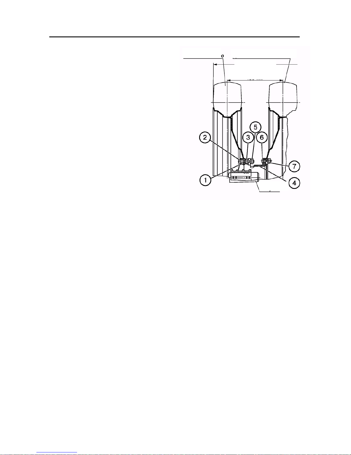
Section E. Unitizing Belarus-510/512 — Operating manual
Main Wheel
Additional Wheel
Installing twin rear wheels
To improve the passing ability, the tractors can be equipped with twin rear tyres
of 15.5R38 size with use of additional
tyres of 15.5R38 size
430 mm
spacers. To install an additional wheel,
unmount the main wheel, press off the
short bolts from the hub (1) and press in
the long bolts (2) supplied with the spacers. To the bolts (2), install the main wheel
and fasten it with the nuts (3). Then install
the spacer (4) on the same bolts and fasten with the nuts (5). After that, install the
additional wheel on the bolts (6) of the
spacer and fasten it with the nuts (7). The
tightening torque of the nuts fastening the
rear wheels is 300 to 350 N•m (30 to 35
kgf•m).
ATTENTION! Installing twin wheels
to increase the hauling capacity is
forbidden.
Half-shaft
64
Page 62
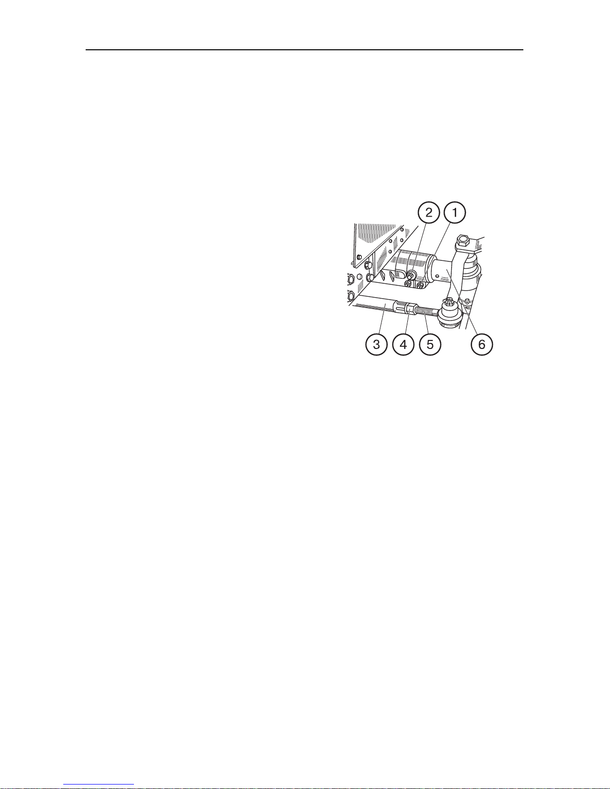
Section F. Adjustments Belarus-510/512 Operating manual
65
Section F. Adjustments
Adjusting front wheel track of steering
booster without cylinder in steering
linkage
The front wheel track can be adjusted
from 1,350 to 1,850 mm with 100 mm increments in case of symmetrical position
of wheels and 50 in case of asymmetrical
position. To adjust the track, proceed as
follow:
a) put a jack under the front of the
tractor and lift the tractor until the wheels
take off the ground. Put a support under
the tractor front to provide secure and
safe tractor position;
b) loosen the bolts (1), remove the
pins (2) fastening retractable knuckles in
the front axle tube;
c) move first one, then the other retractable knuckle (6). At the same time,
change the length of steering rods by rotating the tube (3) in the tips (5), first unscrewing the locknuts (4) to an extent
corresponding to the wheel track to set.
Fasten the knuckles in the front axle
tube.
d) lower the tractor. Check the wheel
toe-in and adjust as necessary.
Page 63
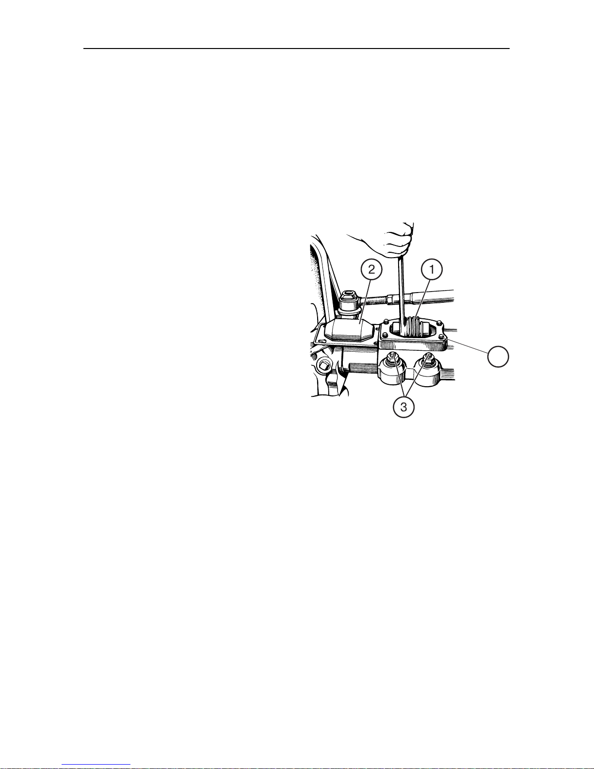
Section F. Adjustments Belarus-510/512 Operating manual
66
4
PTO with bevel gear speed reducers.
Steering booster without cylinder in
steering linkage
The front wheel track is adjusted stepless by a screw mechanism located on
the front axle sleeves in three ranges:
1,350-1,500 mm, 1,500-1,600 mm,
1,600-1,800 mm.
To obtain the required wheel track, set the
mutual bracing of the whee; rim relative to
the disk as shown on the figure below.
For wheels with constant disk offset, the
track is adjusted stepless within 1,400 to
1,600 mm and 1,750 to 1,950 mm.
To change the track, raise the tractor front
(or front wheels in turn), providing a clearance between the wheels and soil, brake
the rear wheels. Put a support under the
tractor front to provide secure and safe
tractor position, after that;
a) unscrew the bolts (4) and remove the
cover (2);
b) release the wedges of sleeves (3) un-
screwing the nuts by an extent ensuring free movement of conical pair
housings.
Rotating the adjustment screw (1) with
a wrench ensures movement of final
reduction gear housings with wheels
in the front axle sleeves and obtaining
the desired wheel track in the specified ranges. Rotation of the adjustment screw must result in changes of
the steering rod length.
Page 64
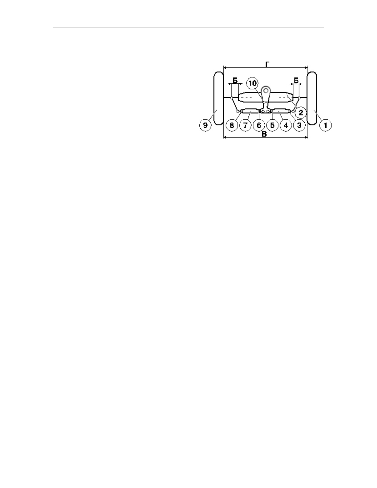
Section F. Adjustments Belarus-510/512 Operating manual
Adjusting front wheel toe-in on tractors with steering booster
Manufacturer sets the front wheel toe-in
withing the range of 0 to 8 mm.
Periodically after each 250 service hours
as well as at each change of front wheel
track check and as necessary adjust the
wheel toe-in. Before checking, adjust
clearances in the wheel bearings and
steering rod joints.
To adjust the wheel toe-in, proceed as
follows:
a) install the tractor on a horizontal hard
surface;
b) set the pitman arm (10) to the middle
position, to do that, turning the steering wheel, set it to a position when the
dipstick in the steering booster housing is buried to a maximum extent;
c) check that the conical pair housings
(for tractors with FDA) or steering
knuckles (for tractors without FDA) be
extended to the length “Б” from the
front axle housing or front axle tube
respectively;
d) adjust the left and right steering rods,
lengthening or shortening them to the
same value, to do that, loosen the
locknuts (3, 5, 6, 8) and by rotating the
left and right tubes (7, 4), set the required length;
e) determine the wheel toe-in by measur-
ing the distance (measurement “Г”)
between the inner flanges of wheel
rims in front (at the wheel center
height) and chalk marks in the measurement points. Then drive the tractor
ahead by a distance, when the marks
be at the rear at the same height and
measure the distance between the
marked points (measurement “В”).
The second measurement must
be greater than the first; the difference between the second “В” and
first “Г” measurements is equal to the
wheel toe-in and must be 0 to 8 mm.
As necessary, adjust the toe-in by
changing the steering rod length. At
that, lengthen or shorten the left and
right rods by the same amount.
f) again check setting of the pitman
arm to the middle position (by dipstick) and the difference between the
measurements “В” and “Г”;
g) lock the steering rod tubes after final
adjustment of wheel toe-in.
67
Page 65
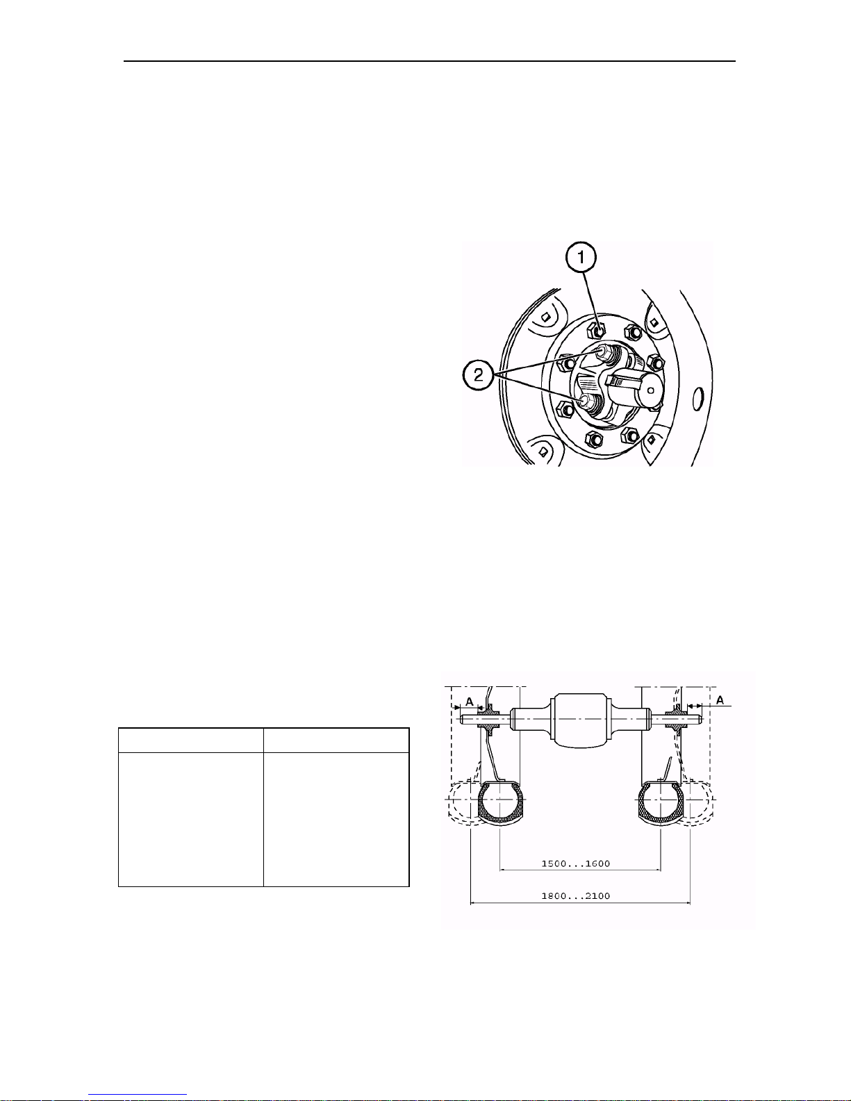
Section F. Adjustments Belarus-510/512 Operating manual
Adjusting rear wheel track
1. Jack-lift the tractor rear part to separate the wheels from the ground. Put
a support under the tractor rear part to
provide secure and safe tractor position;
2. Unscrew the nuts (1) fastening the
wheels and remove the wheels.
3. Loosen the four bolts (2) of the rear
wheel hubs by 3 to 5 turns.
4. Move the hub in one or other direction to obtain the track width (use the
table given below to determine the
track width by measuring the distance “A” from the half-axle end to
the hub face.
5. Tighten the four hub fastening bolts
to a torque of 280 to 300 N•m.
6. Mount the wheel and tighten the fastening nuts to a torque of 210 to 260
N•m.
7. Repeat these operations on the opposite wheel.
NOTE: A track width of up to 1,600
mm can be obtained without changing
the wheel disk position. To obtain a
track width up to 2,100 mm, transpose
the rear wheels assembled with the
hubs as shown in the figure.
Wheel track, mm Distance “A”, mm
1,500 50
1,600 0
1,800 164
1,900 114
2,000 64
2,100 14
When transposing the rear wheels, observe the wheel rotation direction as indicated by the arrow on the tire sidewall.
68
Page 66
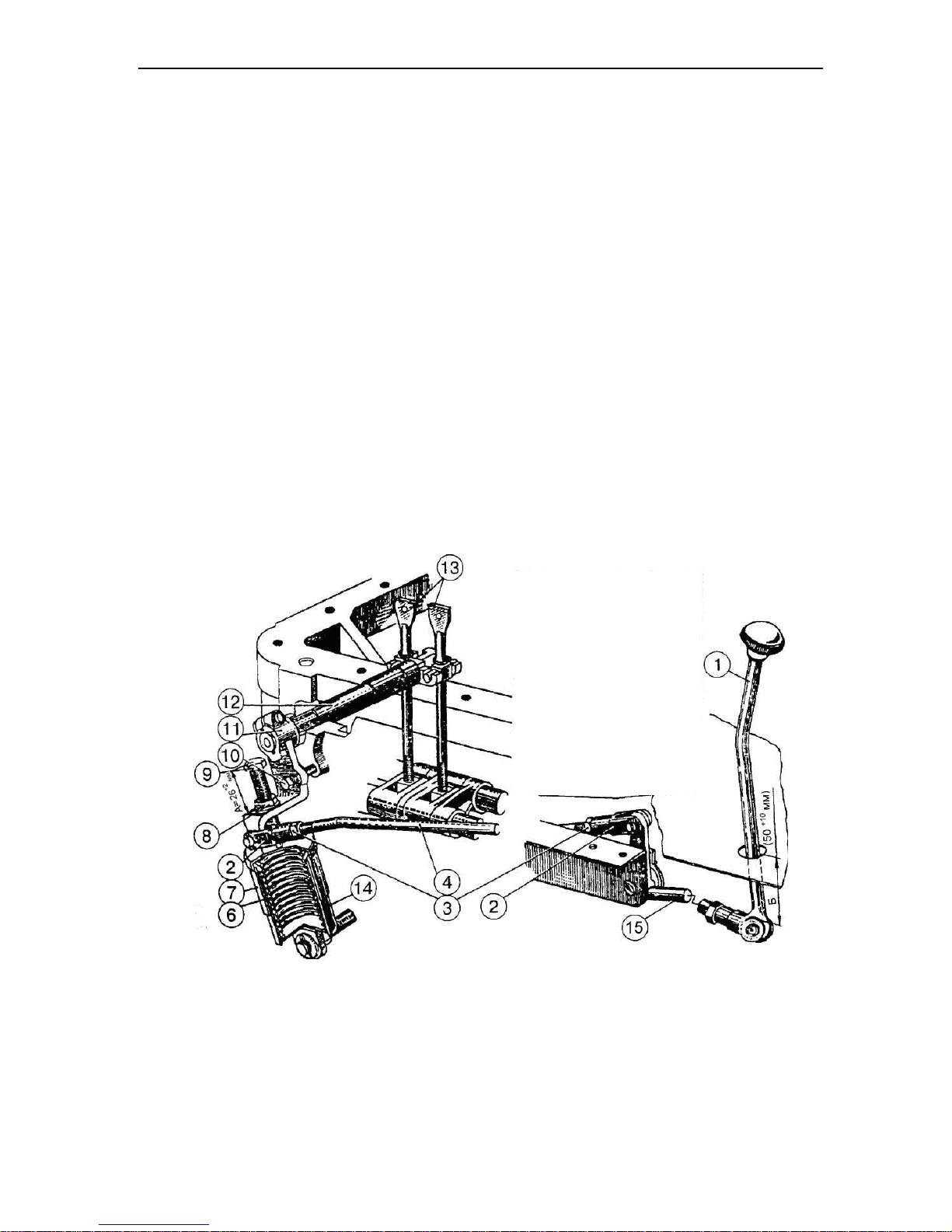
Section F. Adjustments Belarus-510/512 Operating manual
Adjusting power take-off shaft
Adjusting rear PTO control mechanism
When assembled by the manufacturer,
or after a repair (for example, after replacement of brake bands), the control
mechanism is adjusted as follows:
1. Set the eccentric axle 15
в to its initial position so that the flat “C”
(Fig. 2) be at the right side vertically and
fasten it with the lock bar 17 and bolt 16.
2. Disconnect the rod 4 (Fig. 1);
3. Unscrew the bolt 9 to release the spring 6;
To safely disassemble the unit, watch
that when unscrewing the bolt 9 the upper barrel be in constant contact with it
up to a full release of the spring.
4. Remove the rear axle hatch cover to gain
access to the screws 13;
5. Fix the lever 11 in the neutral position introducing the bolt 10 (M10×60) to the hole
on the lever 11 and the hole on the rear
axle housing corresponding to it;
6. Remove the lock bar 26
(Fig. 2), screw in turn the adjusting screws
21 to a torque of 8 to 10 N•m, then unscrew each screw by two turns, at that
screw the screws so that the screw heads
be parallel to the tractor centerline;
7. Remove the bolt 10 (M10×60) retaining
the lever 11 in the neutral position;
8. Screw the bolt 9 directing its tip to the recess in the barrel cover стакана
7 to the dimension “A” equal 26 +2 mm and
lock it with the nut 8;
9. Shift the lever 11 back to the ON position;
Fig. 1 Rear PTO control:
1 - control lever; 2 — adjusting fork; 3, 8 — nuts; 4 — rod; 6 — spring; 7 — outer barrel; 9 — stop
bolt; 10 — adjusting bolt (only for adjustment); 11 — control roller arm; 12 — control roller; 13 —
adjusting screws; 14 — inner barrel; 15 — lever.
69
Page 67
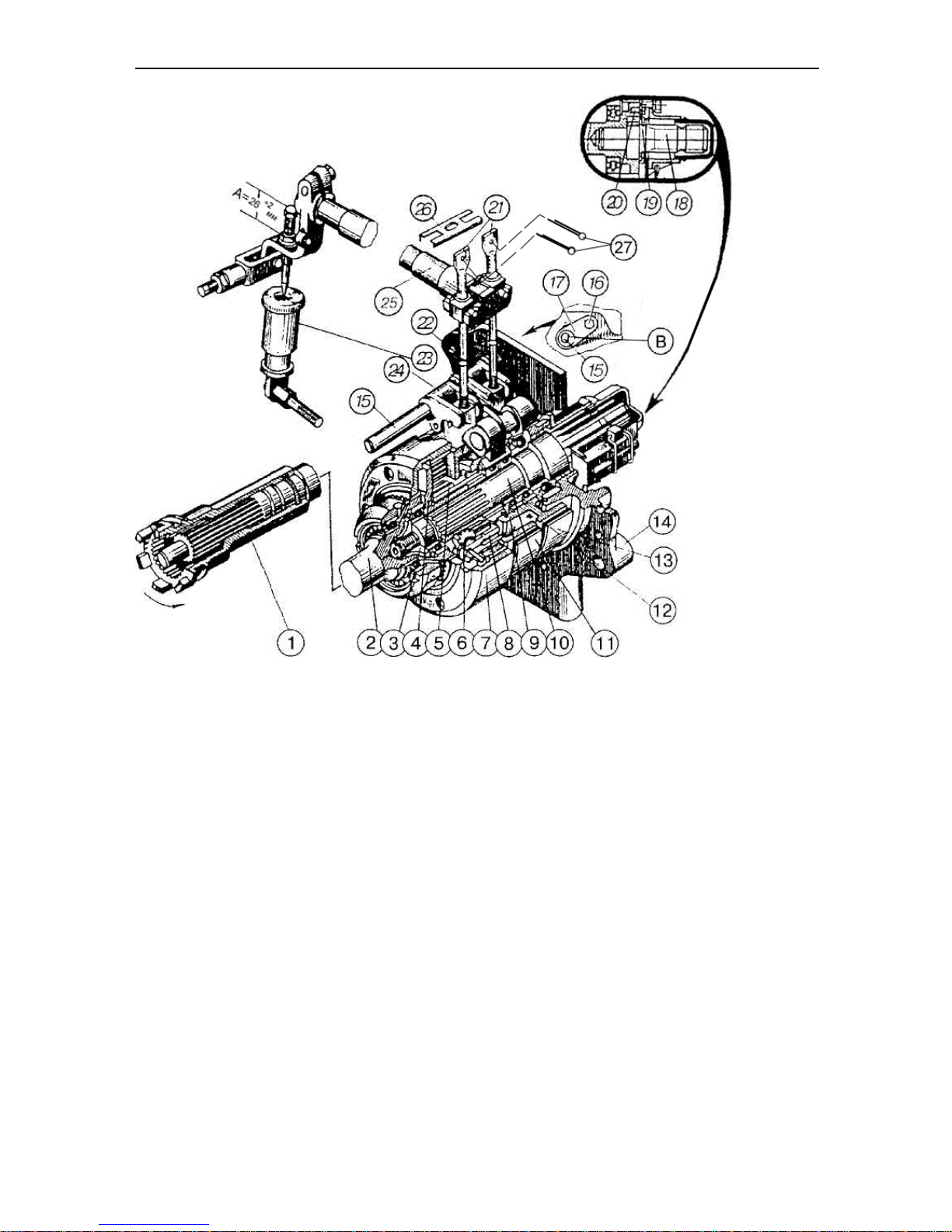
Section F. Adjustments Belarus-510/512 Operating manual
70
Fig. 2 Rear PTO planetary gear:
1 - drive strike clutch; 2 – crown pinion shaft; 3 — nut; 4 — spider; 5 — sun pinion; 6 — planetary
pinion; 7 — crown pinion; 8 — planetary pinion shaft; 9 — brake drum;10 — PTO shaft; 11, 13 —
brake band; 12 — engagement drum; 14 — rear cover; 15 — crank axle; 16 — bolt fastening lock
bar; 17 — lock bar; 18 — replaceable shank; 19 — replaceable shank lock bar; 20 — shank fastening bolt; 21 — adjusting screws; 22, 24 — arm; 23 — spring mechanism; 25 — control roller; 26
— lock bar; 27 — splints.
10. Set the rod 4 (Fig. 1) changing
the length of the rod 4 and arm 15 adjust
the dimension “B” (50
+10
mm).
After adjustment, install the lock bar 26
and splints 27 (Fig. 2) on the adjusting
screws 21, the rear axle hatch cover,
lock the rod 4 and arm 15 (Fig. 1) as
well as the bolt 9.
During operation, external readjustment
is performed when:
a) PTO slips;
b) the control lever 1 stops against
the cab floor when shifted;
c) the engagement force on the lever
1 exceeds 12 to 15 kgf;
in its extreme positions.
Readjustment is performed as follows:
1. Shift the PTO lever 1 to the PTO ON position;
2. Remove the PTO guard.
3. Unscrew the bolt (16), remove the lock bar
(17) from the eccentric axle shank (15)
and rotate the axle clockwise to select a
clearance between the brake band and
drum (in such a case, the PTO shank
cannot be rotated by hand).
4. Fix the axle with the lock bar (17) and bolt
(16).
5. Install the PTO guard to place.
d) the lever 1 cannot be clearly fixed
Page 68

Section F. Adjustments Belarus-510/512 Operating manual
71
IMPORTANT! In case of significant
wear of brake bands, turn the eccentric
axle by 180°, removing excessive
clearances between the brake band
and drum (flat on the left). After that, fix
the shaft with the lock bar (17) and bolt
(16).
After several external readjustments, the
eccentric axle 15 (Fig. 2) takes the leftmost position (the flat “B” is on the left
vertically), which indicates that no more
reserve of external adjustment is available. In such a case, set the eccentric
axle to initial position by rotating it
counter-clockwise (the flat is on the
right vertically), after that perform adjustments as described for PTO control
adjustment for assembly by manufacturer or PTO repair.
When adjustment is correct, the lever 1
(Fig. 1) in the ON position must be at
least 50 mm away from the cab floor
(dimension “B”).
On tractors of earlier make, the PTO external readjustment mechanism may not
be available (pos. 15, 16, 17, Fig. 2). In
such a case, adjust as specified above
for adjustment of PTO control after repair
or in assembly by manufacturer. On
small-cab tractors, the dimension “B” is
50 to 60 mm. PTO brake efficiency, absence of slipping depends only on the
spring mechanism and first of all on
availability of vacant spaces around it and
the levers connected with it. PTO slipping
means that the spring mechanism or the levers meet additional resistance when moved
over due to lack of lubricant in joints, high
contamination, touching adjacent tractor parts
etc.
ATTENTION!
Perform all adjustments with the engine off.
Page 69
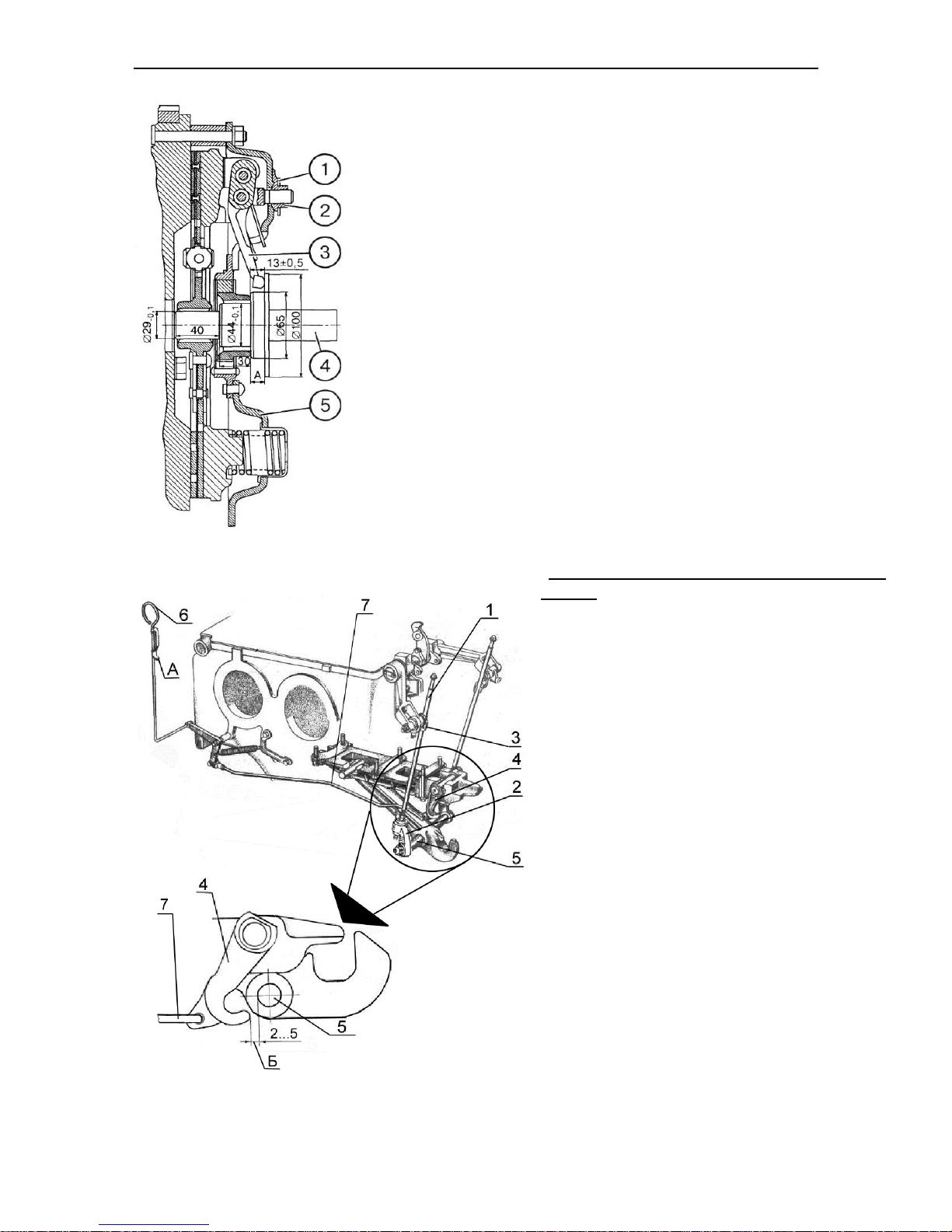
Section F. Adjustments Belarus-510/512 Operating manual
72
ADJUSTMENT OF RELEASE LEVER
POSITION
After installing the clutch onto the flywheel
and removing the mounting bolts, adjust the
position of the release levers 3 with the special mandrel 4 that is based on the inner diameter of the hub splines of the backing
plate 5 resting against the hub end. The
mandrel has an end face for rest of release
levers. The Figure shows the mandrel dimensions. With the adjusting nuts 2 bring
the release levers to stop against the mandrel end, first removing the lock washers 1.
ADJUSTING COUPLING HOOK
CONTROL MECHANISM
ATTENTION! Before adjusting the HDC,
first unscrew the screws 1 from the shack-
Fig. 3
les 2 to ensure free travel of the levers in
order to avoid damage to the brace pins.
To adjust the control mechanism, proceed as
follows:
1. Raise the implement levers to the maximum possible height and adjust the lifting
rod with the screw 1 (see Fig. 3) screw the
screws into the shackles 3 up to stop of the
screw heads against the surfaces of the
shackles 2 and lock them with locknuts. At
that the catches 4 must go under the axis of
the hook 5 without touching it.
2. Lift the handle 6 and install the element
A of the clamp 6 into the hole in the cab
floor.
3. By adjusting the length of the rod 7, ensure the clearance B between the catches
Fig. 4
4 and the axis of the hook 5 when it is
lowered or raised (see Fig. 4).
4. Raise the levers to the upper position
and lower the handle 6. At that the catches 4 must settle under the hook axis.
5. Make sure that when the levers are
lowered, the catches ensure locking the
hook in the working position.
ADJUSTING REAR AXLE
DIFFERENTIAL LOCK CONTROL
For normal operation of the differential lock
control, correctly adjust the relationship of
Page 70
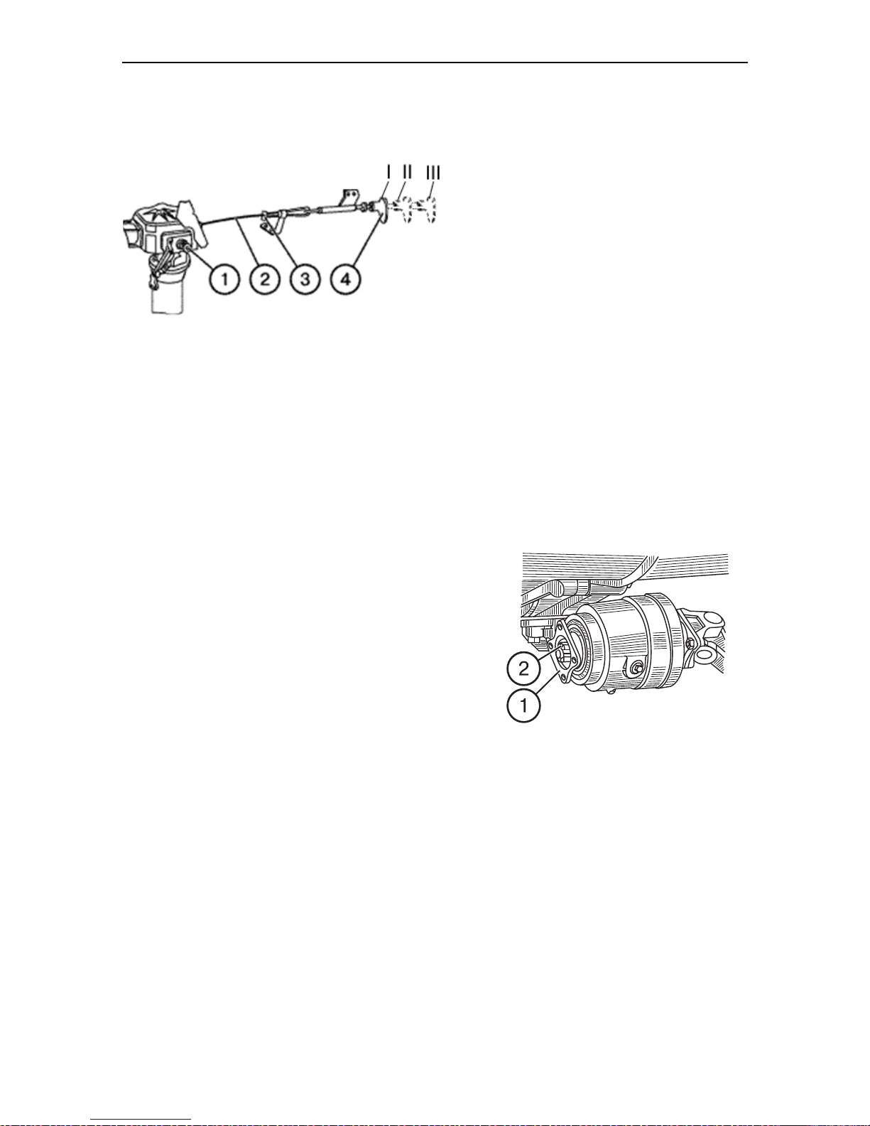
Section F. Adjustments Belarus-510/512 Operating manual
73
the handle 4 and the cock 1 of the lock
sensor, proceeding as follows:
a) fasten the free end of the cable 2 in
the clamp with the screw 3, at that
the cable end must protrude from the
clamp to 5 to 10 mm max.;
b) shift the handle 4 to the position I.
Stretch the cable until the cock starts
turning and lock the coupling with
the screws 3; lead the second clamp
up against the coupling and fasten it
with the screw.
To check correctness of the adjustment,
shift the handle to the fixed position II, at
that the mark on the cock 1 must align
with the mark “вкл.” (“on”) on the lock
sensor cover. The handle and the cock
must return to the position I from the positions II and III under action of the
spring.
ADJUSTING FDA CARDAN DRIVE
In the cardan drive, adjust the safety
coupling in the intermediate support and
check the side play in the cardan bearings.
Adjust the safety coupling to transfer of a
torque of 40 to 80 kgf•m (400 to 800 N•m).
Adjust the coupling by tightening the nut 2 of
the rear shaft shank of the intermediate support to ensure transfer of the required torque.
Periodically check the side play in the universal joint cross bearings. If any play is present, disassemble the joint and check condition of the bearings and crosses, replace
worn parts. When assembling the gland
holders, press them in up to stop against the
bearing.
The driveshaft is balanced dynamically. Do
not disassemble the driveshaft without a
special need. When replacing parts such as
pipe with joint forks and flange during operation, balance the driveshaft assembly with
two joints again dynamically by welding
plates to the both ends of the pipe. Unbalance must not exceed 55 g•cm. Do not crank
the driveshafts with tire levers, keys or other
devices to avoid damage to sealings and
failures of cross bearings.
Page 71
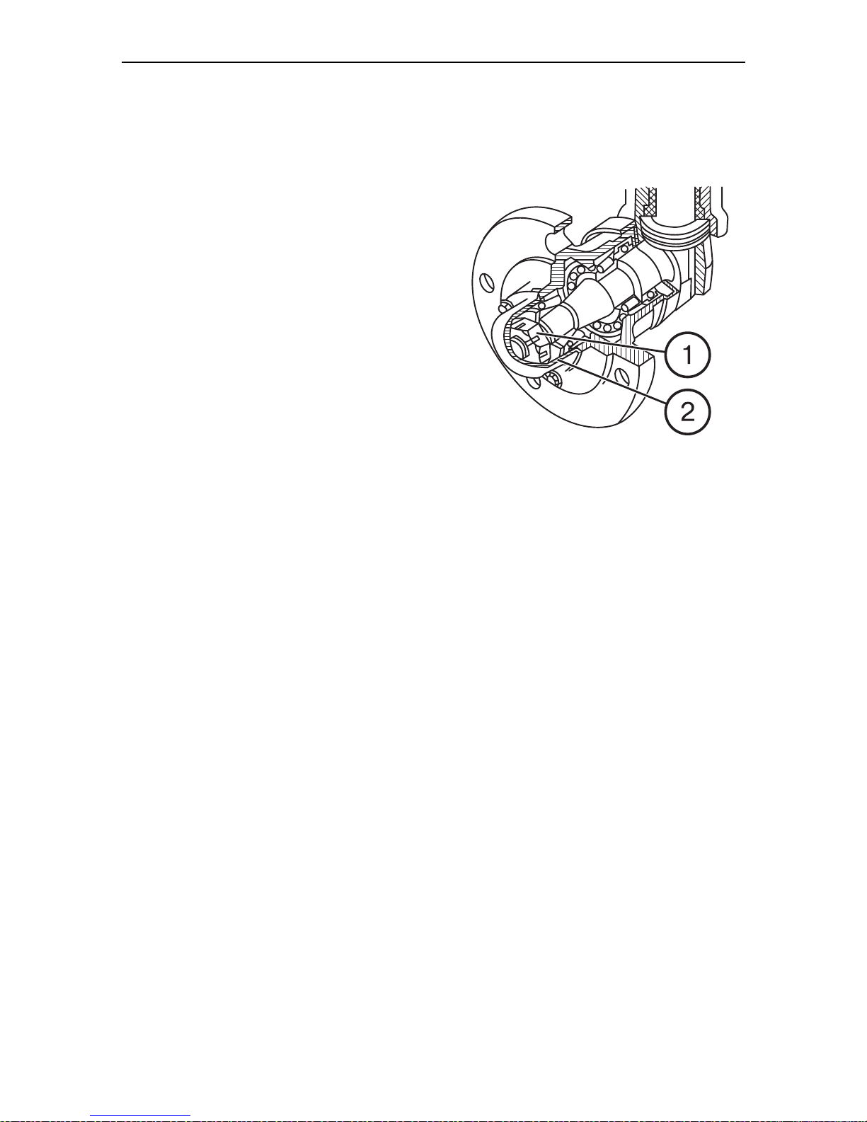
Section F. Adjustments Belarus-510/512 Operating manual
74
Adjusting tapered roller bearings of
wheel guides of Belarus 510 tractors
When adjusting bearings of wheel
guides, set the axial clearance of 0.08 to
0.20 mm. Check it after each 1,000 service hours. To do that, raise the wheel
and slightly rocking it in the direction
perpendicular to the rotation plane, determine the bearing clearance.
If a high clearance is determined, adjust
proceeding as follows:
a) unscrew the bolts and remove the
cap 2;
b) unsplint the castle nut 1 and, rotating
the wheel by hand, tighten the nut 1
until a high resistance to wheel rotation appears. Then unscrew the nut
only to an extent allowing to obtain
alignment of the nearest slot of the
nut with the cotter-pin hole in the
half-axle.
c) check easy rotation of the wheel;
d) fasten the nut with a cotter pin, in-
stall the cap to place first filling it with
grease.
Page 72

Section G. Maintenance Belarus– 510/512 Operating manual
Section G. Maintenance
KINDS OF MAINTENANCE OF THE TRACTORS
Kind of maintenance
Maintenance during the tractor pre-operation:
MS during the tractor preparation for
running-in
MS during running-in
MS after completion of the running-in
Scheduled maintenance:
shift-time maintenance (STM)
maintenance No. 1 (MS-1)
maintenance No. 2 (MS-2)
maintenance No. 3 (MS-3)
Special maintenance
General maintenance
Seasonal maintenance (M-SS and M-FW)
Maintenance under special application conditions
Maintenance during storage
Frequency or term of maintenance organization in tractor service hours
Prior to running-in preparation
MS during running-in
After 30 service hours
8-10
125
500
1000
2000
As necessary
When transferring to fall-winter operation (M-FW) and spring-summer operation (M-SS)
When preparing to operation under special conditions
During long-time storate
MAINTENANCE WHEN PREPARING THE TRACTOR FOR OPERATION
Maintenance during the tractor
preparation for running-in
essary, clean the terminals from oxides and grease them with technical
petroleum, clean the vents and check
• clean the tractor from dust and dirt,
remove preservative grease (if any);
• check oil level and add as necessary:
engine crankcase; air cleaner tray;
tank of the hydraulic mounted system; power train housing; steering
booster housing; FDA and intermediate support housings;
• Lubricate steering knuckle bearings;
pinion of the right angle brace; bushings of the rear attachment mechanism;
the charge;
• check and adjust as necessary tension of the fan belt; the tractor control
units; air pressure in the tires; and the
toe-in of the front wheels;
• check and tighten, if necessary, outer
threaded joints;
• fill the radiator with coolant;
• listen to the engine operation and
check readings of the instruments for
conformance to prescribed norms.
• check the storage battery and, if nec-
75
Page 73

Section G. Maintenance Belarus– 510/512 Operating manual
Maintenance during the running-in:
• check the level of and add as necessary oil into the engine crankcase and
coolant into the radiator;
• monitor clogging of the air cleaner
against the pilot lamp;
• check serviceability of the engine,
controls, lighting and signalling systems, and brakes.
Maintenance on completion of running-in (after 30 service hours):
• inspect and wash the tractor;
• listen to operation of the major parts
of the tractor;
• check and adjust as necessary tension of the fan and alternator belt, free
travel of the clutch and brake pedals;
• check storage batteries and as necessary clean the battery surfaces, terminals, wire lugs and vents in the plugs;
• change oil in the engine crankcase,
air cleaner tray, housings of power
train, FDA and intermediate support;
• lubricate the clutch shifter bearing;
• clean the centrifugal oil filter;
• replace the filtering element of the hydraulic system;
• flush the screen oil pre-filter of the
engine;
• check and tighten as necessary external fastenings of the tractor components, including the bolts of the engine
cylinder head and the bolts fastening
the driveshaft intermediate support
holder to the transmission housing (for
tractors with FDA), the bolts of power
train housings, rear wheel hubs, pivoting shaft holder and the nuts of the
front and rear wheels;
• check and adjust clearances between
the engine valves and rockers;
• check coolant level and add it as necessary to the radiator;
• drain sediment from the fuel coarse filter;
• check and restore, if necessary, air
tightness of the air cleaner and engine inlet pipelines;
• check serviceability of the engine, illumination and signalling systems.
76
Page 74

Section G. Maintenance Belarus– 510/512 Operating manual
77
SCHEDULED MAINTENANCE TABLE
Pos.
No.
Object of maintenance
Check
Clean Lubricatie Replace Adjust Drain
Flush Note
Shift-time maintenance (STM) after each 10 service hours
1 Oil in engine +
2 Coolant +
3 Oil in hydraulic system tank +
3а Steering +
Maintenance No. 1 (MS-1) after each 125 hours of operation
4
Oil in air cleaner tray
5
Oil level in casings of upper
+
+
bevel pairs of the FDA with
bevel reducing gears
6
Sediment of fuel coarse filter
+
and fuel tanks
7 Fan and alternator belt + +
8 Hub and wheel fastening + +
9 Air pressure in tires + +
10
Clutch shifter bearing
+
11 Storage batteries + +
12
Oil level in FDA cardan drive in-
+
termediate support
13*
Play in steering rod joints
13*
Steering booster
а
14*
Clutch pedal free travel
+ +
+
+ +
Maintenance No. 2 (MS-2) after each 500 service hours
Rotor of engine centrifugal oil fil-
15
ter
+
16 Oil in engine** +
17 Clearances in engine valves + +
18 Steering wheel play + +
19
Brakes (service and parking)
•
Perform the operation after each 250 service hours.
+
+
** When using summer grade diesel fuel with sulfur content of 1%, intervals for crankcase oil change are reduced by half.
Page 75

Section G. Maintenance Belarus– 510/512 Operating manual
78
No. Object of maintenance
20
Front wheels (toe-in)
21 Engine air cleaner +
22 Hydraulic system filter*
23 Alternator +
24
Deposit of fuel fine filter
25 Transmission oil +
26 Oil in the FDA housings +
27
Maintenance of steering drive
Flushing steering booster drain
28
filter
Lubricating front axle steering
29
knuckles
30
Bolts fastening cylinder head
31
Fuel coarse filter
Filtering element of fuel fine fil-
32
ter
Check
+
+ +
+
+
Maintenance No. 3 (MS-3) after each 1000 service hours
+
Clean Lubricatie Replace Adjust Drain
+
+
+
+
End of Table
Flush Note
+
+
33 Alternator +
34 Steering rod joints** + + +
35 Angle brace of mounted attach-
Shaft bushings of mounted at-
36
tachment mechanism
37
External boltings of tractor
38 Oil in hydraulic system tank +
39 Transmission oil +
Oil in FDA housings and in-
40
termediate support
41
Engine oil pre-filter
42 Engine breather +
43 Adjustment of steering booster +
+
+
+
+
+
+
*) First change after 500 hours, subsequent changes after 1,000 service hourse as well as during seasonal maintenance.
**) After each 250 service hours.
Page 76
Section G. Maintenance Belarus– 510/512 Operating manual
79
No.
44
45
46
47
48
Object of maintenance
Engine injectors
Fuel pump. Injection lead
angle
Fuel pump. Adjustment at
test bench
Engine cooling system
Valve of centrifugal oil filter
Check
Clean
Lubricatie
Replace
Adjust
Maintenance after each 2,000 service hours
+
+
+
+
General maintenance
+
Seasonal maintenance
Drain
+
+
+
End of Table
Flush Note
+
Page 77
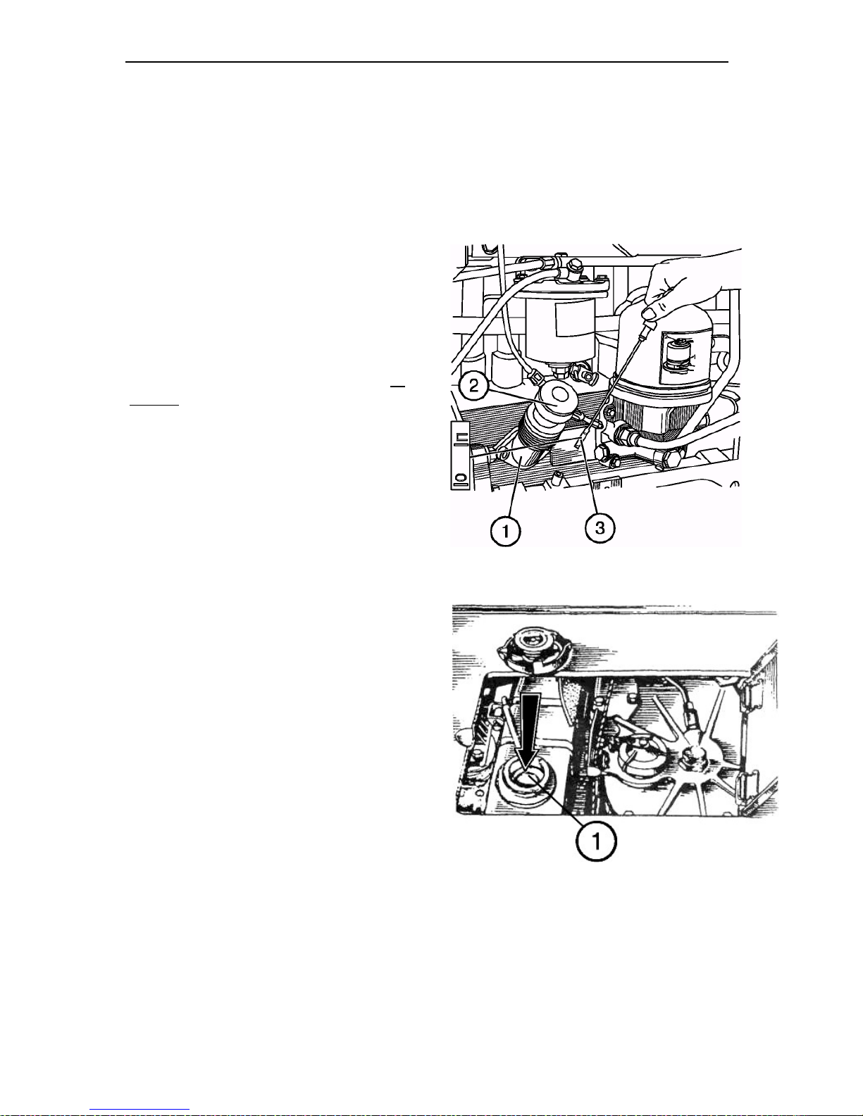
Section G. Maintenance Belarus– 510/512 Operating manual
80
Shift-time maintenance (STM) after each 10 service hours or daily
Operation 1. Oil level in engine crankcase.
Stop the engine, wait for 15 minutes and
check the oil level. The oil level must be
between the upper and lower marks of the
dipstick (3). If necessary, remove the cover
(2) of oil filler neck (1) and add oil to the
upper mark of the dipstick (3)
IMPORTANT! Do not operate the engine
with oil below the lower mark of the oil
dipstick.
IMPORTANT! Do not fill up oil above
the upper dipstick mark. Excessive oil
will burn, giving the fail impression of high
oil consumption for burning.
Operation 2. Coolant level in engine
radiator.
Remove the radiator cap away and check
the cooling fluid level, which shall be below
the upper edge of the filler neck (1) by 5060 mm. If necessary, add coolant to the
level.
IMPORTANT! Do not allow the level to
drop below 100 mm from the filler neck
upper edge.
WARNING! The engine cooling system
operates under pressure maintained by
the valve in the radiator cap. It is dangerous to remove the cap from a hot
engine. Let the engine cool down, put
thick cloth on the cap and turn it slowly
to reduce the pressure before removing
the plug fully. Beware of burns caused
by hot liquid!
Page 78
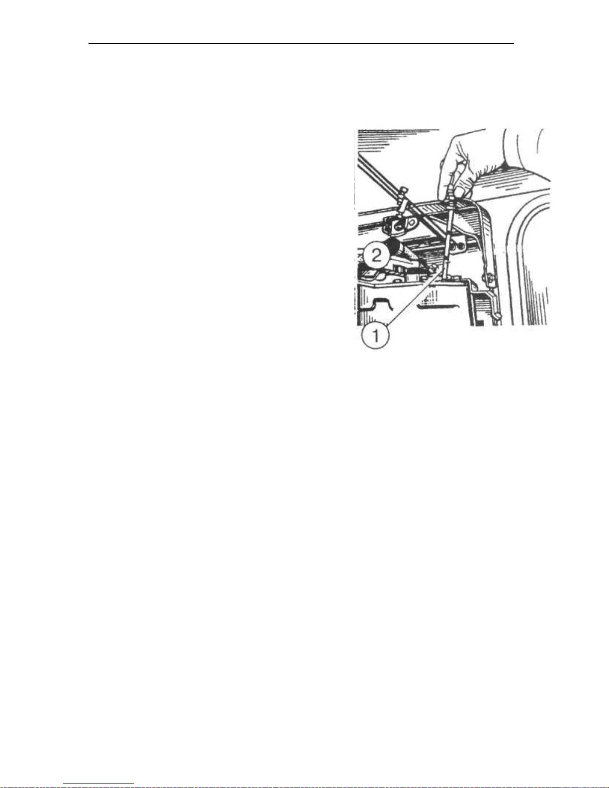
Section G. Maintenance Belarus– 510/512 Operating manual
81
Operation 3. Checking the oil level in the
hydraulic system tank
NOTE: Prior to checking the oil level,
place the tractor on an even horizontal
surface. Stop the engine and engage
the parking brake.
Check the oil level by the oil dipstick (1)
on the left side of the hydraulic system
tank. The level shall be between the
marks “О” and “П” (Full). If necessary,
add oil to the mark “П±5мм” removing
the threaded plug (2).
NOTE: When using machines requiring high amount of oil taking, add oil to
the level corresponding to the upper
mark “С”. When doing this, the hydraulic cylinders must be with plungers retracted.
Operation 3a. Steering
Check serviceability of the steering. Inspect, listen to, check on run.
Page 79
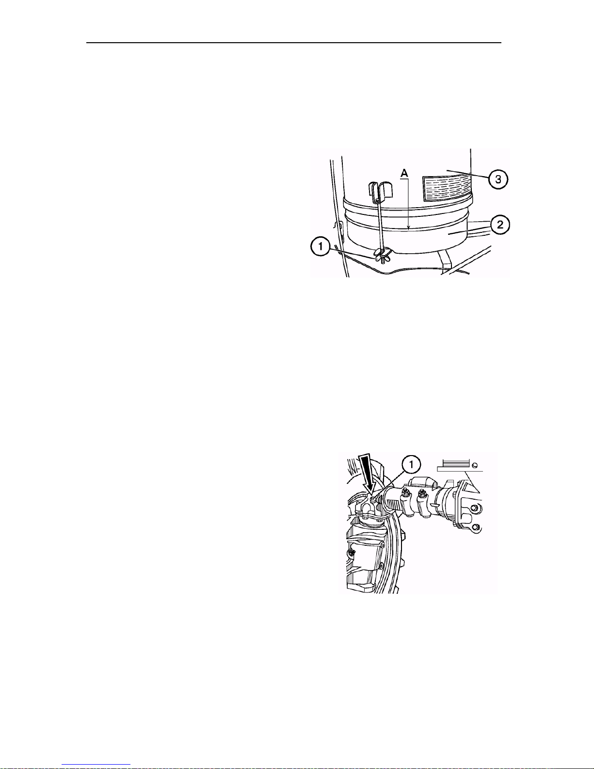
Section G. Maintenance Belarus– 510/512 Operating manual
82
Maintenance No. 1 (MS-1) after each
125 service hours
Perform the previous actions plus as follows:
Operation 4. Oil level and condition in
engine air cleaner tray
Loosen the two nuts (1) and remove the
tray (2) of the air cleaner (3). Check the oil
level in the tray, which shall be at the level
of the ring collar “A”.
Add oil, if necessary. If oil is contaminated
with dirt or in oil, change oil.
ATTENTION! Do not overfill the tray
with oil above the ring collar “A”, since
it can result in oil ingress into the engine combustion chambers and development of false impression about increased oil consumption for burning.
Operation 5. Oil level in housings of
upper bevel pairs of FDA with bevel
reducing gears
Check that the oil level coincides with the
lower edge of the oil-filling hole (1). If
necessary, add oil.
Page 80
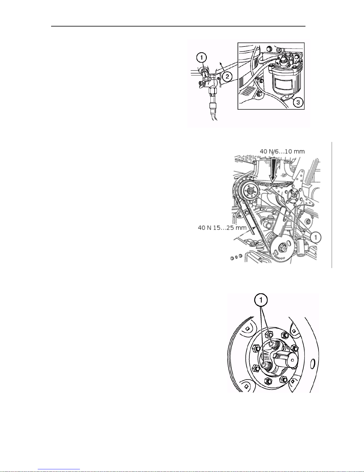
Section G. Maintenance Belarus– 510/512 Operating manual
Operation 6. Draining sediment from
fuel tanks and fuel coarse filter
Open the drain plugs (1) of the fuel tanks
(2) and the drain plug (3) of the filter and
drain sediment until clean fuel appears.
Drain sediment into a special container
and dispose of it properly.
Close the drain valves after appearance of
clean fuel without water and dirt.
Operation 7. Checking tension of fan
belt of engine cooling system
Check the belt for traces of wear or damage. If necessary, replace it.
To check tension of the belt of the engine
alternator with an elongated shield, apply
a force of 40 N approx. to the middle pint
of the belt section “alternator pulley to water pump pulley” (1). The deflection must
be 6 to 10 mm. If necessary, adjust the
belt tension by rotating the alternator body,
having loosened the lath fixing bolt and the
alternator fixing nuts, and then tighten
them.
NOTE: When fitting a normal alternator
shield, check the belt tension on the section
“alternator pulley – crankshaft pulley”. The
belt deflection shall be within the range
15…20 mm under a force of 40 N approx.
applied to the middle of the section.
Operation 8. Rear wheel hubs
• Check tightening and, if necessary,
tighten the bolts (1) fastening the real
wheel hubs (four bolts on each hub)
with a torque spanner. The tightening
torque must be 300 to 400 N•m (30 to
40 kgf•m).
• Check and adjust as necessary the
nuts of:
• front wheels to a torque of 200 to 250
N•m
• rear wheels to a torque of 300 to 350
N•m
• fastening of the disks to the rims to a
torque of 180 to 240 N•m.
83
Page 81
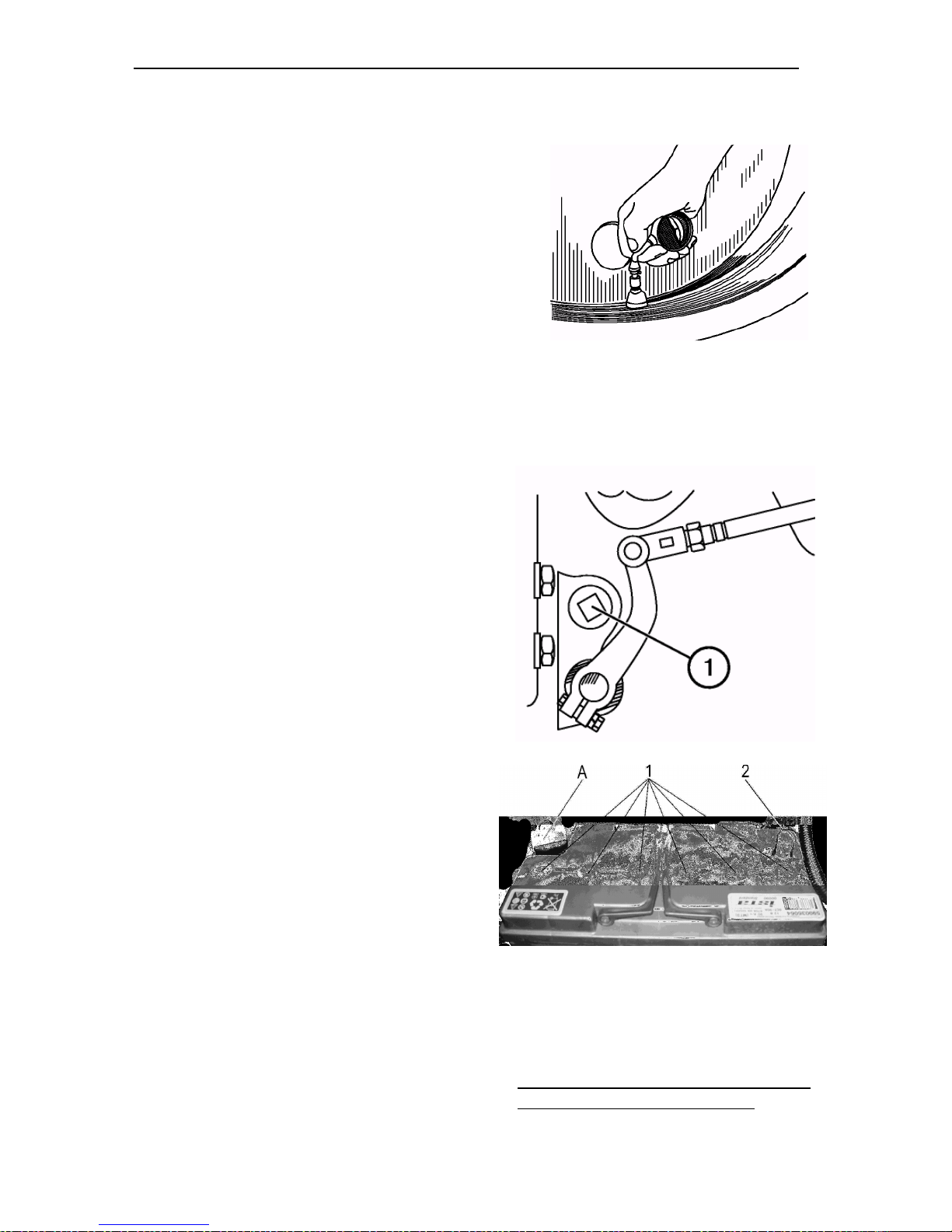
Section G. Maintenance Belarus– 510/512 Operating manual
Operation 9. Air pressure in tires
Check the tread condition and air pressure in the tires. If necessary, adjust the pressure ac-
cording to the recommendations given in this Manual.
Operation 10. Lubricating clutch
shifter bearing
Remove the plug (1) from the left side of
the clutch housing.
Insert the injector of the lever-plunger
pressure gun into the opening and make
4 to 6 injections of Litol-24 grease
through the oil feeder screwed into the
shifter body to lubricate the release
bearing.
NOTE: Do not inject excess grease,
since it will be accumulated inside the
clutch housing and can get on the friction surfaces of the driven disk friction
facings.
Operation 11. Storage batteries
WARNING: Batteries contain sulfuric ac-
id that causes severe burns when getting
onto open parts of the body. Beware of
the acid getting onto the skin, into eyes
and onto clothes. When the acid gets onto external body parts, wash them with
plenty of pure water. In case of ingestion,
drink plenty of water or milk.
In case of contact with the mucous
membrane of an eye, wash it with plenty
of water for 15 minutes and then call for
medical assistance. Do not allow spark
84
of flame getting into electrolyte zone;
this can result in explosion. Charge
the batteries in a ventilated room.
When servicing the batteries, wear
protective goggles and gloves.
Keep the batteries dry and clean.
Make sure that the batteries are fixed re-
Page 82
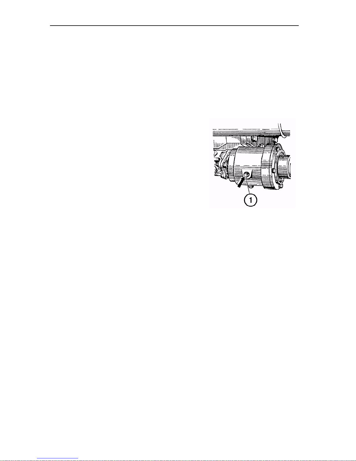
Section G. Maintenance Belarus– 510/512 Operating manual
liably. Before you remove the plugs, clean
the adjacent surfaces.
Check the electrolyte level. It must be
above the protective mesh by 12 to 15
mm (or between the level marks on the
battery transparent body).
Prior to adding distilled water, check the
Operation 12. Checking oil level in intermediate support of FDA cardan
drive
Check the oil level in the intermediate
support. If necessary, add oil to the level
of the lower edge of the filler opening
closed with plug (1).
electrolyte density in each cell jar. If
necessary, add distilled water.
Check that terminals (2) under the
jackets (A) and plugs (1) are clean. If
necessary lubricate the terminals (2)
with technical petrolatum.
85
Page 83
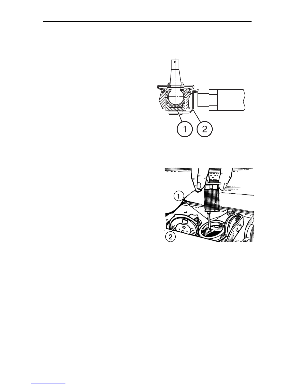
Section G. Maintenance Belarus– 510/512 Operating manual
86
Operation 13*. Checking backlashes
in steering rod joints
After each 250 service hours, check the
joints by shaking them by hand or rotating the steering wheel.
To adjust a steering rod joint, procede
as follows:
a) remove the safety wire (3) from the tip
(3);
b) tighten the plug (1) with a wrench to
eliminate a clearance in the rotary
joint;
c) lock the plug with safety wire.
NOTE: If backlashes in in the joints cannot be eliminated by tightening the
threaded plugs, disassemble the joint
and replace worn-out parts.
Operation 13а*. Check oil level in
steering booster housing
Remove the plug 2 and take the dipstick
1 from the steering booster housing. Oil
must be at the level of the upper mark on
the dipstik 1.
In case of low oil level, add oil to the
mark.
___________________________________
* Perform MS after each 250 service hours.
Page 84
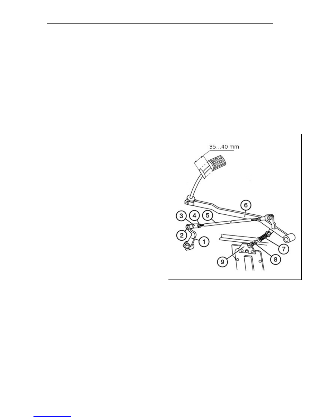
Section G. Maintenance Belarus– 510/512 Operating manual
87
Operation 14*. Adjusting free travel of
clutch pedal
IMPORTANT! A too long pedal travel
will not allow to the clutch to be fully disengaged and will make the gear switching difficult. Absence of a free pedal travel will cause slipping of clutch disks,
quick wear of friction facings and overheating of the clutch parts.
To adjust free clutch pedal travel:
• Unsplint and remove the pin (2), having disconnected the rod (5) from the
lever (1).
• Loosen the locknut (4).
• Unscrew the bolt (8) so that the pedal
rod (6) would move upwards to the
stop against the cab floor.
• Turn the lever (1) counterclockwise to
the stop, i.e. when the release bearing
touches pressing arms.
• By unscrewing the fork (3), align the
openings in the fork with those in the
lever (1), and then screw the fork into
the rod (5) by 5 to 5.5 turns (i.e. make
the rod shorter). Link the fork (3) with
the lever (1) with the pin (2).
• Assemble the leverage of the clutch
pedal in reverse order.
IMPORTANT! Make sure that the clutch
pedal returns reliably to the stop against
the floor at the distance of free pedal
travel. Otherwise, adjust the servo-unit
springs (7) by means of the bolt (8) or
reposition the holder (9) by turning it relatively to the fastening bolt axis.
___________________________________
* Perform MS after each 250 service hours.
Page 85
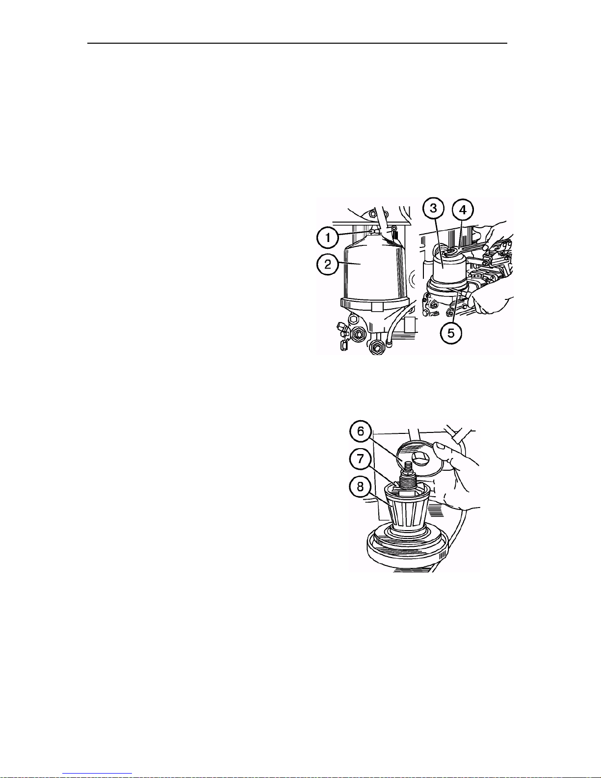
Section G. Maintenance Belarus– 510/512 Operating manual
88
Maintenance No. 2 (MS-2) after
each 500 service hours
Perform the previous MS actions plus as
follows:
Operation 15. Centrifugal oil filter of
engine
• Unscrew the nut (1) and remove the
• Insert the screwdriver (5) or a rod be-
• Remove the cover (6), impeller (7)
• Remove deposits from the inner walls
• Clean all the parts in a detergent solu-
• Reassemble the filter by performing
• Align the balancing marks of the bar-
• The rotor must rotate freely, without
• Install the cap (2) to place and
cap (2).
tween the filter body and the rotor bottom to lock the rotor (3) against rotation and remove the rotor barrel (3) by
turning the rotor nut with spanner (4).
and filtering grid (8) of the rotor. If
necessary, clean and flush the grid.
of the rotor barrel using a nonmetallic scraper.
tion and blow with compressed air.
the same operations in the reverse order. Prior to assembling the barrel with
the rotor casing, lubricate the seal ring
with motor oil.
rel with those on the rotor casing.
Tighten the barrel-fastening nut with
a slight force until the barrel is fully
set on the rotor.
jamming.
tighten nut (1) to a 35 to 50 N•m
(3.5 to 5.0 kgf•m) torque.
NOTE: After stopping the engine, the
noise of a turning rotor must be head
for 30-60 s. This indicates that the filter operates properly.
Page 86
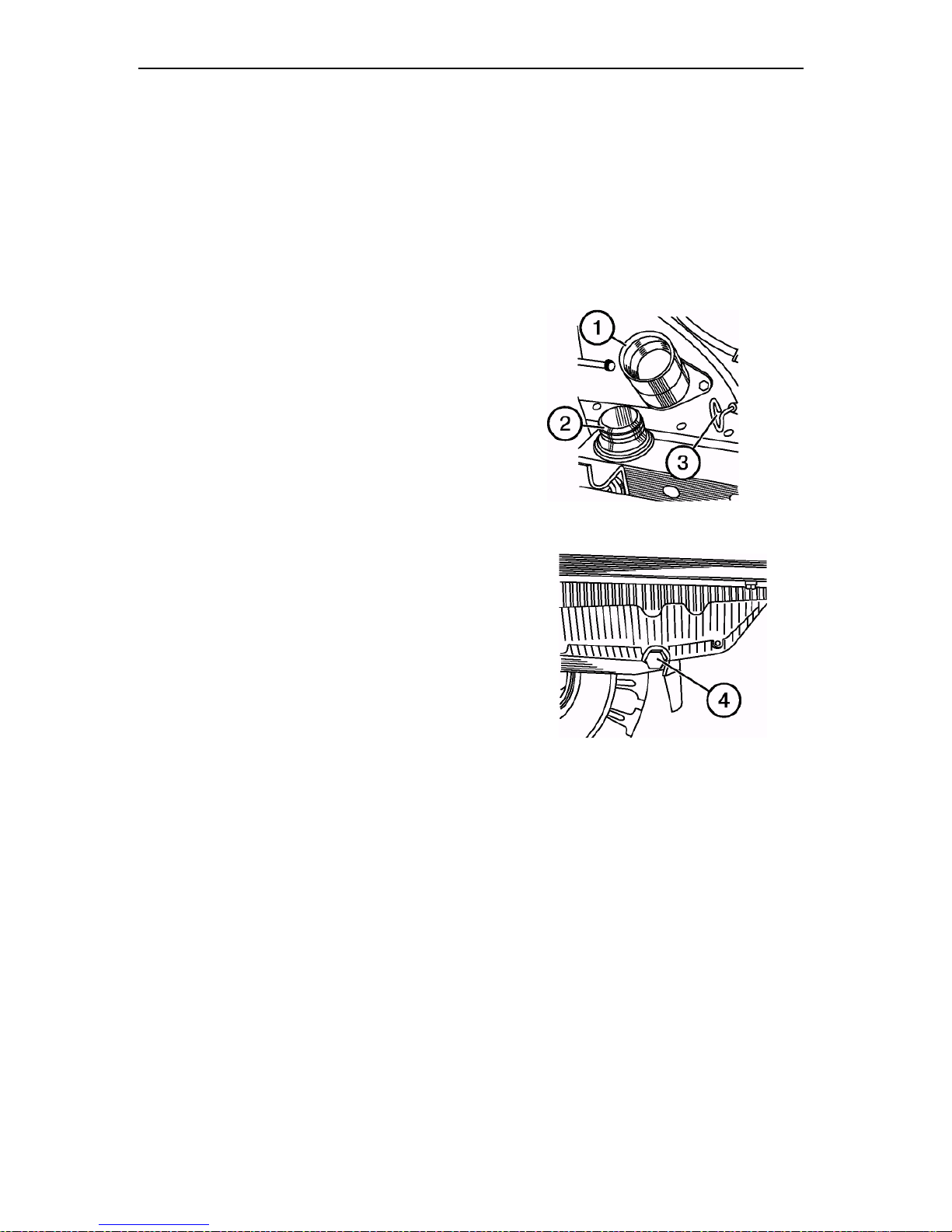
Section G. Maintenance Belarus– 510/512 Operating manual
89
Operation 16. Changing oil in engine
• Warm up the diesel engine to the
normal operating temperature (70°C
min.).
• Place the tractor on an even surface,
stop the engine and engage the parking brake.
• Remove the cap (2) of the oil filler neck
and unscrew the drain plug (4).
ATTENTION! Be careful to avoid contact with hot oil.
Drain oil into a container for waste oil
storage.
• Place the drain plug (4) to place and fill
in fresh motor oil through the oil filler
neck (1) (M-8ДM, M-8Г2, M-8Г2K during
winter and M-10ДM, M-10Г2, M-10Г2K
during summer to the upper mark of the
dipstick (3).
• Install the filler neck cap (2) to place.
• Start the engine and let it run for 1-2
minutes.
• After 10 minutes from the moment of
stopping the engine, check oil level
with the dipstick.
• If necessary, add oil.
Page 87
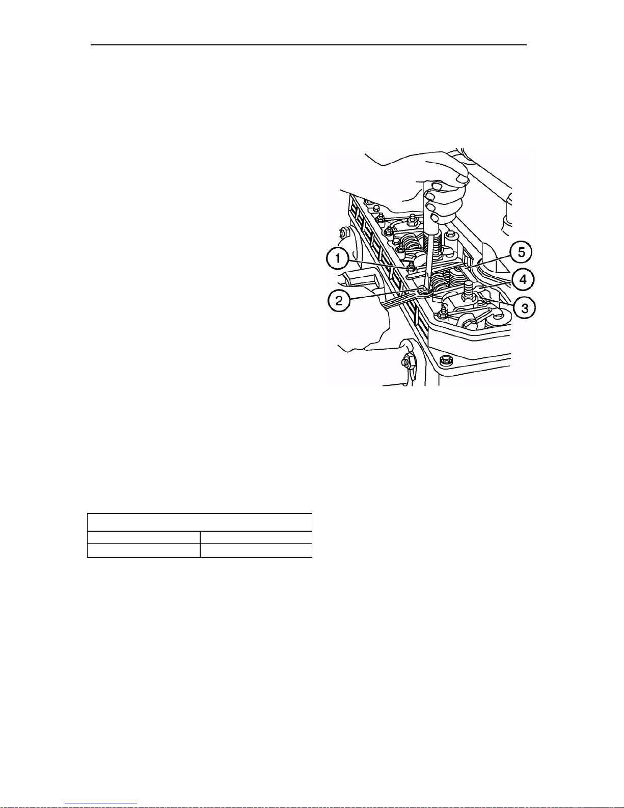
Section G. Maintenance Belarus– 510/512 Operating manual
90
Intake valves
Exhaust valves
Operation 17. Checking clearances between valves and rockers
NOTE: Check the clearances on a cold engine, first checking tightening of the cylinder
head bolts.
To perform the adjustment, proceed as
follows:
• remove the cylinder head cover cap
and check the fastening of the rocker
axle rests. The nut tightening torque
must be 60 to 90 N•m (6 to 9 kgf•m);
• crank the engine crankshaft until the
moment of closing of the valves of the
1st cylinder (the intake valve starts
opening, the exhaust valve finishes
closing) and adjust clearances in the
4th, 6th, 7th and 8th valves (counting
from the fan);
• to adjust the clearance, loosen the
locknut (1) of the screw (2), insert
the feeler (5) between the face of
valve rod (3) and the rocker head
(4) and set the required clearance
against the feeler by turning in or
out the screw (2).
• turn the crankshaft through 360°, set
the valve closing at the 4th cylinder
and adjust clearances in 1st, 2nd, 3rd
The clearances between the rocker
head and the valve rod face on a cold
engine for intake and exhaust valves are
specified in the table below:
and 5th valves as shown above;
• after adjustment of the clearances,
tighten the locknuts (1) and refit the
removed parts.
Belarus 510/512
0,20.. .0,35 0,20.. .0,35
Page 88
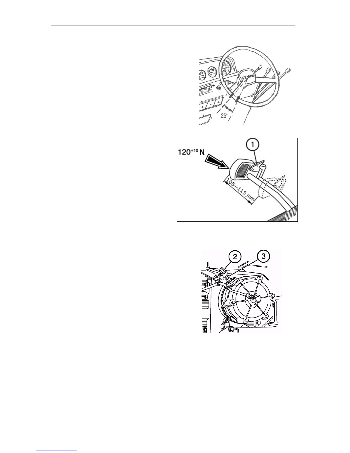
Section G. Maintenance Belarus– 510/512 Operating manual
91
Operation 18. Steering wheel play
When the engine is running, the
steering wheel play must not exceed
25°. If no so, check and eliminate plays
in the joints of the hydraulic cylinders and
the steering rod.
Operation 19. Adjusting service and
parking brakes. Adjustment of the
brake valve and pneumatic system
pressure regulator
To adjust the brake control, proceed as
follows;
a) unscrew the locknuts (3) of the ad-
justing bolts (2);
b) screw the bolts (2) into the adjust-
ment forks or unscrew then so that
the full brake right pedal travel would
be 105 to 115 mm under a force of
120 to 130 N. The travel of the left
brake pedal must be less by 5 to 20
mm to provide a simultaneous brake
actuation in interlocked condition. Reduction of brake pedal travel below
the values specified below is not allowed as it results in premature wear
of brake linings and brake overheat-
ing;
c) tighten the locknuts (3). Interlock the
pedals with the lock strip (1) and check
simultaneous action of the right and left
brakes in motion (1 m max. by the footprint). Ingress of lubricant into the brake
causes the disk oiling and reduces the
friction between their working surfaces,
brakes do not act. In such a case, disassemble the brake, eliminate the oil leakage, wash the oiled disks with gasoline
and let them dry for 5 to 8 minutes. After
assembly, adjust the brake control.
Page 89
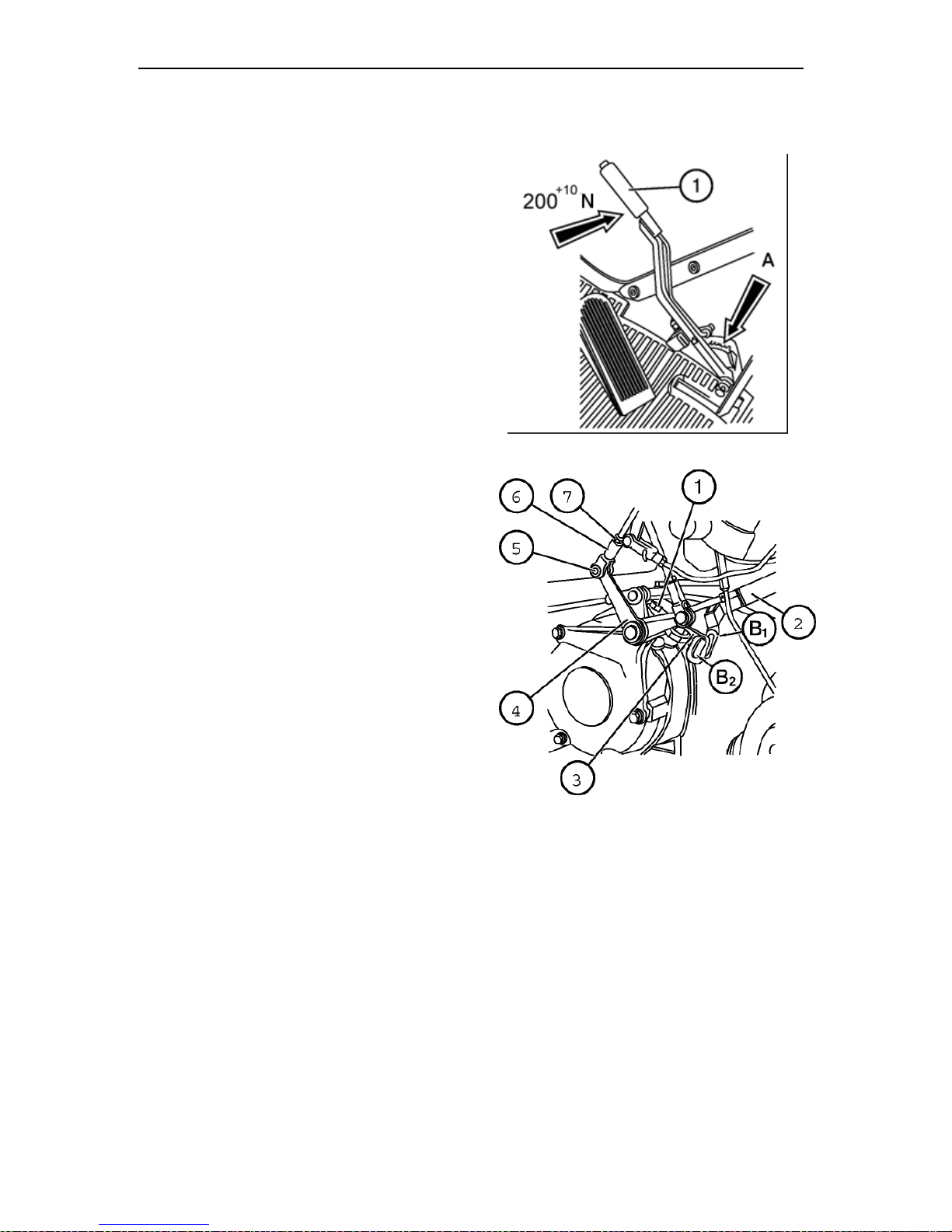
Section G. Maintenance Belarus– 510/512 Operating manual
92
To adjust the parking brake, install the
tractor on an even surface, stop the engine, wedge the rear wheels from the
front and behind, and proceed as follows:
a) shift the parking brake control lever
(1) to the front position (from your-
self);
b) loosen the tightening of adjusting
bolt locknut (1) (see the lower figure
below), as well as the locknut (7)
and remove the pin (5);
c) turn the arm (4) and align the upper
edge of the slot “B1” of the arm (2)
with the upper edge of the slot “B2”
of the arm (3) of the right brake pe-
dal and then align the openings of
the arm (4) with those of the fork (6)
by rotating the fork (6) and then in-
sert the pin (5);
d) screw the bolt (1) in or out so that
when moving the control lever to-
wards yourself with the force of
+10
200
N, the latch would be retained in the dent between the third
and the forth teeth of sector “A”,
and the tractor would be held on
18% slope. After adjustment, tighten
the loosened locknuts.
Operation 20*. Front wheel toe-in.
The front wheel toe-in must be 0 to 8
mm. If necessary, perform the adjusting
operations according to the recommendations given in the section “Adjustments”.
___________________________________
* Perform MS after each 250 service hours.
Page 90

Section G. Maintenance Belarus– 510/512 Operating manual
93
Operation 21. Checking air-tightness
of air cleaner and inlet duct joints
• Remove the monocyclone (1) and
clean its inner surface.
• Loosen the clamps (2), remove the
bolt (4), release the clamp (3) and
remove the air cleaner (5).
• Disassemble the air cleaner, having
loosened the nuts (7) and removed the
tray (6).
• Clean the inner tray cavity and fill in
fresh motor oil.
• Extract three filtering elements, rinse
them in diesel fuel and blow with
compressed air. Clean the central
pipe. Reassemble the air cleaner
and install it onto the engine.
• Check air-tightness of all joints and, if
necessary, tighten them up. An engine
operating at a medium crankshaft
speed (1000 rpm) must stop when
shutting off the air intake pipe.
Page 91
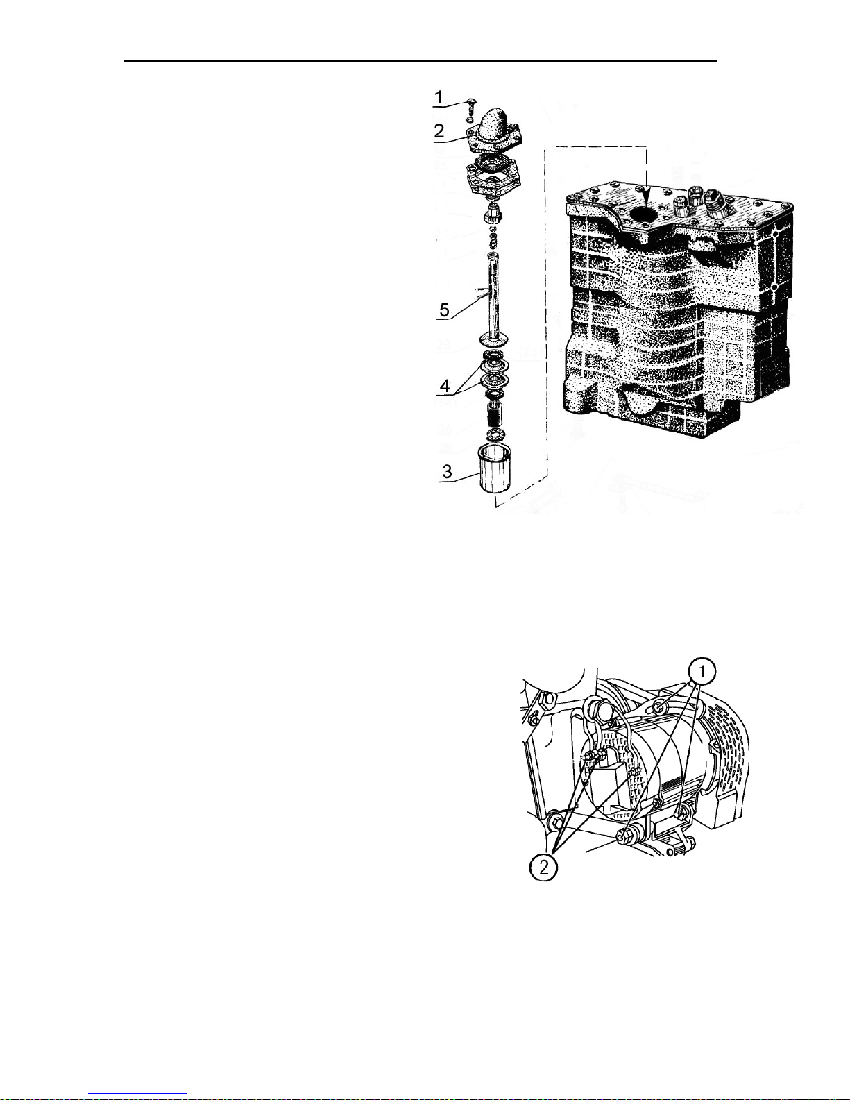
Section G. Maintenance Belarus– 510/512 Operating manual
94
Operation 22. Flushing hydraulic system oil filter
NOTE: Subsequent flushings of the
hydrualic system oil filter must be performed after each 1,000 service hours.
• Unscrew the bolts (1) and remove the
cover (2), take out the filter housing
assembly (3).
• To flush the filtering elements (4),
take them out of the housing (3) by
removing the wire (5).
• Flush the elements in detergent solution and after flushing perform the operations in the reverse order.
• Install the filter assembly into the hydraulic system tank, close it with the
cover (2) and screw the bolts (1).
Operation 23. Cleaning alternator
Clean the alternator from dust and dirt.
Check and tighten, if necessary, the alternator fastening bolts (1). Check the condition and firmness of the alternator
clamped connections (2).
Page 92
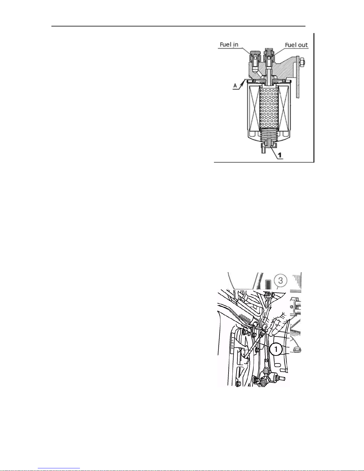
Section G. Maintenance Belarus– 510/512 Operating manual
Operation 24. Draining sediment from
fuel fine filter
Drain sediment after each 250 service
hours of the engine.
Remove the plug 1 in the lower part of the
fuel fine filter by 2 to 3 turns as per the
figure and drain sediment until clean fuel
free of water and dirt appears. Tighten the
plug.
Operation 25. Oil level in transmission
Check oil level by using the oil dipstick (1)
on the left side of the gearbox. The normal
working oil level must be between the upper and lower marks on the dipstick.
If you have to correct oil level, remove
the plug (3) on the upper cover of the
gearbox and add oil to the level.
95
Page 93
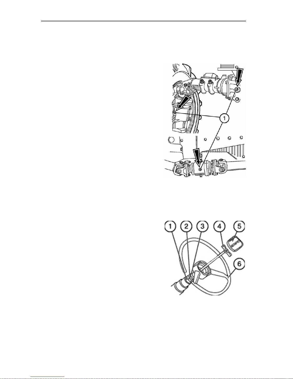
Section G. Maintenance Belarus– 510/512 Operating manual
Operation 26. Oil level in FDA housing.
FDA with bevel reducing gears
Check the oil level in the:
1. wheel reducing gears (lower bevel
pairs);
2. main gear (front differential) hous-
ing;
3. cardan drive intermediate support;
4. upper bevel pair housings.
The oil level must be up to the lower
edges of threaded check holes (1).
If necessary, add oil to the level through
the check holes.
Operation 27. Maintenance of steering
drive
Maintenance of the steering drive consists of periodical checks of tightening of
the threaded connections.
To ensure minimum vibration of the
steering wheel, adjust the steering column as follows:
• remove the cover (5);
• unscrew the screw 4 and remove
the steering wheel 6;
• loosen the locknut 3.
• screw in the nut 2 until it touches
the bushing 1 so that clearances in
connections be chosen;
• unscrew the nut 2 by 1.5 turns
and lock it with the locknut 3;
• install the steering wheel 6 adjusting
its height and screw in the clamp 4.
96
Page 94
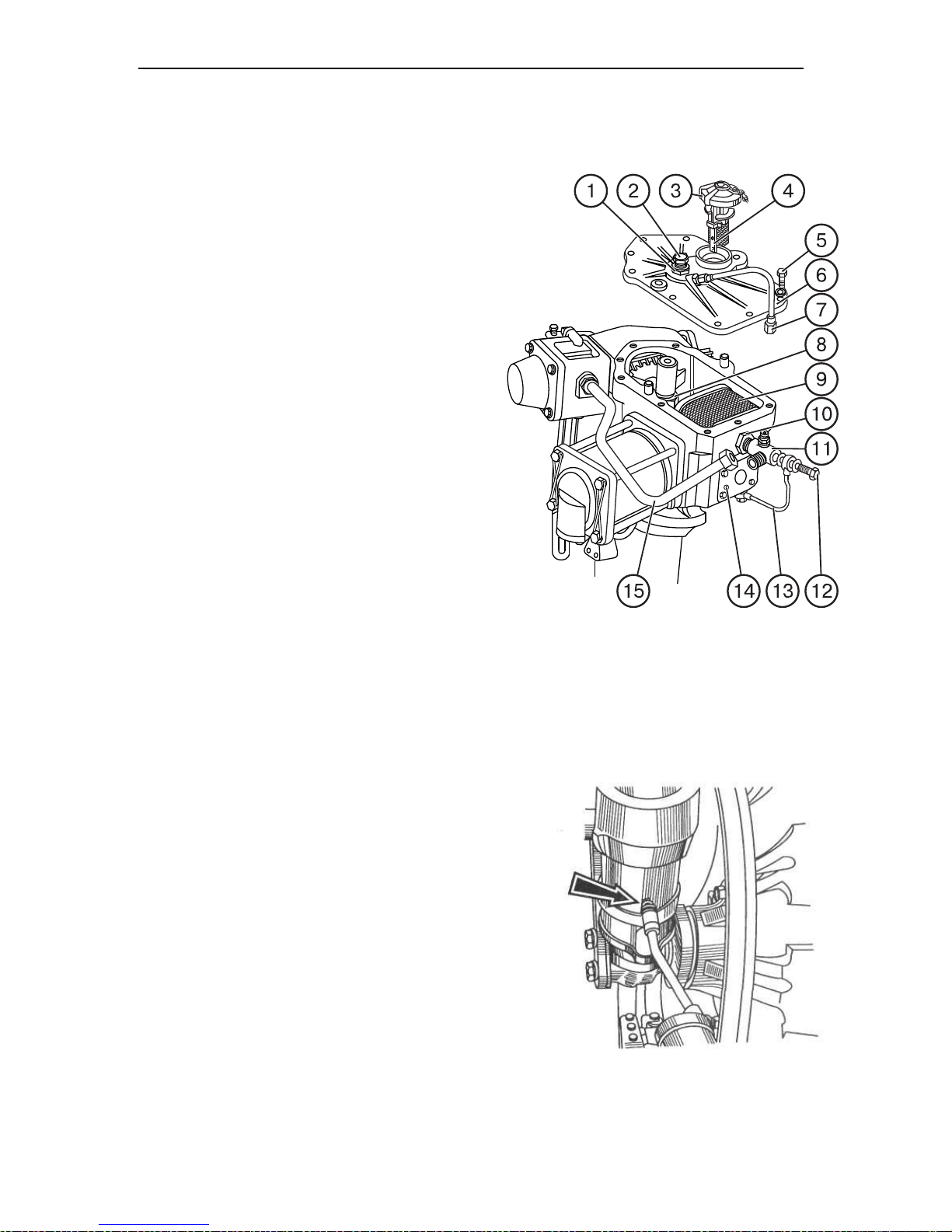
Section G. Maintenance Belarus– 510/512 Operating manual
97
Operation 28. Flushing steering
booster drain filter
To flush the oil filter, proceed as follows:
a) raise the facing;
b) disconnect the oil ducts 7, 13 and
15, unscrew the bolts 5 fastening the
cover 6 to the housing, remove the cover using two unmounting bolts.
c) screw out the relief valve 11 and
remove the drain filter 9;
d) flush the filter in detergent solution;
e) tighten the nut 8 of the pivoting
shaft;
f) install the filter and perform the
operations in the order reverse to disassembling.
g) at the same time, adjust end play
of the steering shaft, proceeding as follows:
loosen the locknut 1 and screw in the
adjustment bolt 2 up to stop against the
shaft end, then unscrew it by 1/8 to 1/10
turn and lock with the locknut 1.
Operation 29. Lubricating front axle
steering knuckles (Belarus 510)
With a gun, make 10 to 12 injections of
grease through pressure lubricators
(one lubricator per each knuckle). The
Litol-24 grease must be used.
Page 95
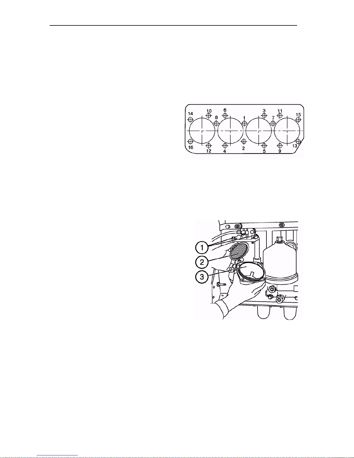
Section G. Maintenance Belarus– 510/512 Operating manual
Maintenance No. 3 (MS-3) after
each 1,000 service hours
Perform the previous MS actions plus the
following operations:
Operation 30. Tightening torque of
engine head bolts
NOTE! This operation must be only per-
formed on a warmed up engine.
Remove the rocker cover, cylinder head
cover and rocker axle assembly.
Using a torque spanner, check and tighten the cylinder head bolts in the order
shown in the figure on the right. Bolt
tightening torque must be 160 to 180 N•m
(16 to 18 kgf•m).
Operation 31. Engine fuel coarse filter
Wash the fuel coarse filter proceeding as
follows:
• Shut off the fuel tank valve.
• Unscrew the fastening bolts (1) of the
barrel (3) and remove the barrel.
• Unscrew the deflector with the mesh
(2) and remove the diffuser.
• Wash the deflector with the mesh, the
diffuser and filter barrel in diesel fuel.
• Assemble the filter parts in the reverse order.
• Fill the system with fuel.
Bleed the system and remove air from
fuel system as shown below (action
40).
98
Page 96
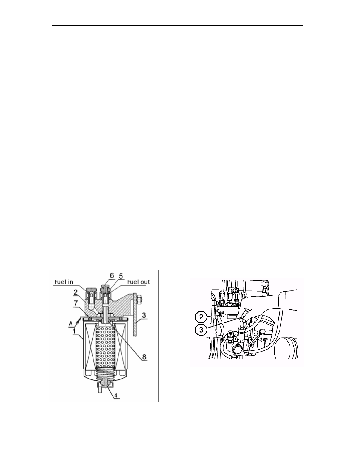
Section G. Maintenance Belarus– 510/512 Operating manual
99
Operation 32. Replacing filtering element of fuel fine filter
• Service life of a fuel fine filter depends on purity of fuel applied.
• Replace the filter as per the figure
proceeding as follows:
• - drain fuel from the filter by unscrewing the plug 4 in the lower part
of the housing
Do not let the fuel to spill over, drain it
only to a container.
• - unscrew the filter 1 from the adapter 8 in the housing 2 and install a
new filter instead of it, which is supplied assembled with the gasket 7
that must be first lubricated with motor oil;
• - after the gasket 7 touches the installation seat A on the housing 2,
screw in the filter by an additional ¾
turn. At that, screw in the filter only by
force of the hands;
• - open the fuel tank valve and fill the
system with fuel.
1 - filter ФТО20-1117010; 2 – housing; 3
— holder; 4 — plug (to drain sediment); 5
— return line pipe; 6 — plug (to bleed
air); 7 — gasket; 8 — adapter.
• To bleed air from the system:
• To bleed air from the system, unscrew
the plug 6 on the bolt fastening the return line pipe by 2 to 3 turns. Purge
the system with the hand purge pump
3, screwing in the plug when fuel
without air bubbles emerges.
• Unscrew the plug 2 on the fuel pump
housing. Purge the system with the
hand purge pump until fuel without air
bubbles emerges, screwing in the
plug 2 at that.
• Instead of the FT020-1117010 filter
other sealed fuel filters can be installed with basic specifications and
dimentions as follows:
• screening capacity 90% min.;
• conditional throughput capacity at a
pressure difference of 0.01 MPa of
150 l/h min.;
• diameter 95 to 105 mm;
• height 140 to 160 mm;
• connection thread M16×1.5;
• gasket outer diameter 70 to 75 mm.
Page 97

Section G. Maintenance Belarus– 510/512 Operating manual
Operation 33. Alternator
Remove the driving belt (1) from the
alternator pulley (2).
Check the easy rotation of the alternator
rotor and presence of plays in the bearings.
If there are any plays or jamming of the
rotor, remove the alternator and send it
to the shop for repair.
100
Page 98
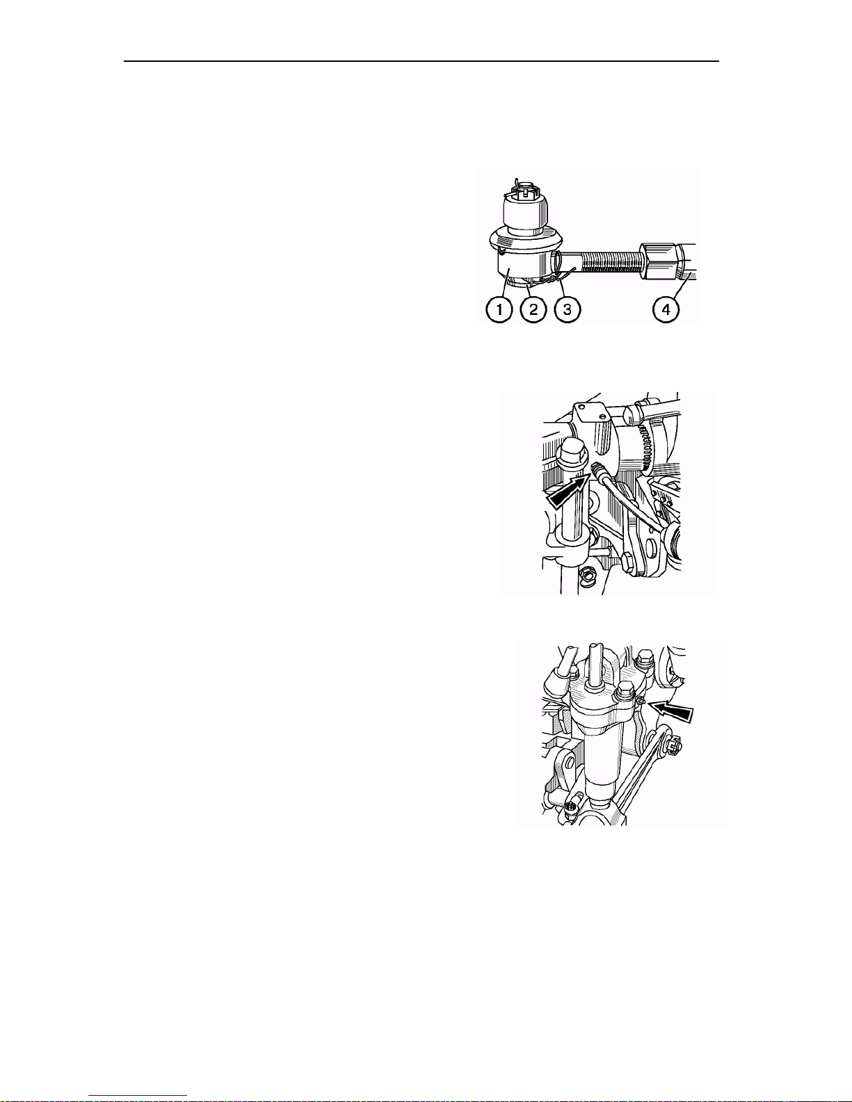
Section G. Maintenance Belarus– 510/512 Operating manual
Operation 34. Steering rod joints
When the engine is running, turn the
steering wheel in both direction to check
free travel and plays in the joints (1) of
the steering rod (4).
If there are any plays in the joints, proceed as follows:
• remove the lock wire (3);
• tighten up the threaded plugs (2);
• lock the plugs with the wire (3).
NOTE: If plays in in the joints cannot
be eliminated by tightening the threaded plugs, disassemble the joint and
replace worn-out parts.
Operation 35. Lubricating RHL right angle brace bearing
Lubricate the adjustment mechanism of
the right angle brace through the pressure lubricator (one point of greasing)
using a gun. Make 4…6 injections with
the gun. The Litol-24 grease must be
used.
gearbox casing — rear axle casing;
rear axle casing — RHL and HDC
holders;
front and rear cab supports, holders
and pins of the steering hydraulic cyl-
Operation 36. Lubricating bushings of
RHL pivoting shaft
Apply grease using a gun through the
pressure lubricators in the mounted attachment holder until grease appears
from the gaps. The Litol-24 grease must
be used.
Operation 37. Outside bolted connections
Check and tighten, if necessary, the critical bolted connections:
• front and rear wheel nuts and rear
wheel hub bolts;
• front beam — semi-frame side members;
• half-frame side members – clutch
casing;
• HDC plate fastening;
• diesel engine — clutch casing;
• clutch casing — gearbox casing;
inder;
rear axle casing — semi-axle
sleeves;
FDA casing - sleeves — wheel re-
ducing gears;
101
Page 99
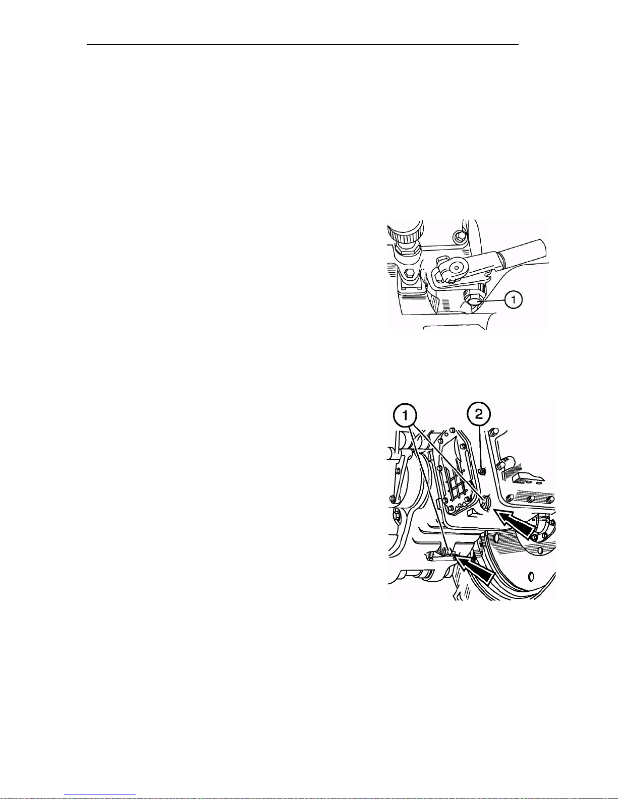
Section G. Maintenance Belarus– 510/512 Operating manual
nuts of the cardan shaft collars;
nuts of the FDA casing wedges;
casing of the cardan drive intermediate
Operation 38. Changing oil in hydraulic system
• Prior to changing oil, warm up oil in the hydraulic system.
• Place the tractor on an even surface, lower and detach the mounted machine.
• Brake the tractor and stop the engine.
• Unscrew the filler cap and the drain plug (1)
from hydraulic system tank and drain oil into
a waste oil container.
ATTENTION! Be careful to avoid contact
with hot oil. Dispose of waste oil properly.
• Install the drain plug (1) to place and fill the
system with fresh oil. Refit the filler cap.
Operation 39. Changing oil in transmission
• Prior to changing oil, warm up the transmission.
• Install the tractor on an even surface, lower the mounted machine and stop the engine.
• Engage the parking brake and lock the
wheels against movement by using wedges.
• Unscrew the plug (2) and drain plugs (1)
from the casings of rear axle and gearbox, and drain oil into a special waste oil
container. Dispose of waste oil properly.
ATTENTION! Be careful to avoid contact with
hot oil.
• Fill the transmission with fresh oil. Install the
plug (2) to place.
102
support — clutch casing;
fastening of the holders of the lifting
HDC and hydraulic lift.
Page 100
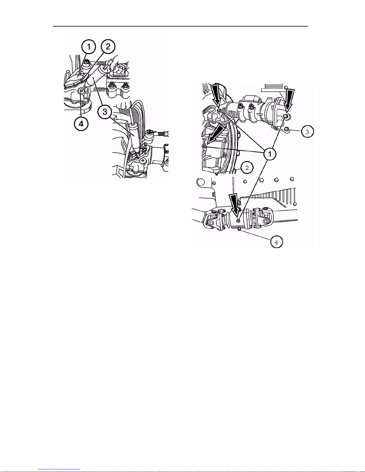
Section G. Maintenance Belarus– 510/512 Operating manual
Operation 40. Changing oil in
FDA and intermediate support housings
drain plugs.
•Fill the casings with fresh transmission oil
Taп-15В, Tсп-15K, Tsp-10, TAД-17и or their
analogues to the level of lower edges of the
filler openings.
FDA with bevel reducing
gears
• Prior to changing oil, warm up
oil in the FDA housings.
• Install the tractor on an even
horizontal surface. Engage
the parking brake and wedge
the rear wheel from the front
and behind.
• Unscrew the check filler caps
(1) and drain plugs (2, 3, 4)
from the casings of wheel reducing gears, main gear and
intermediate support, respectively. Drain oil into a special
container.
ATTENTION! Be careful to
avoid contact with hot oil. Dispose of waste oil properly.
• Install and tighten up the
To drain oil from upper bevel pair casing:
- using the gun (3) for liquid lubricant, pump
out some oil through the filler opening (4);
- unscrew the bolts (2), remove the cover (1)
and drain the remaining oil;
- install the cover (1) and bolts (2) to
place;
-fill the spaces of upper bevel pairs up to
the lower edges of the opening (4) using a
gun for liquid lubricant.
- install and tighten up all the check/fill plugs.
103
 Loading...