

Page 1

BELARUS
1221.2/1221В.2
1221.3
1221 – 0000010РЭ
OPERATORS MANUAL
2009
Page 2

Operators manual was composed by engineer of the first Department of Constructive and
Experimental Work, M.V. Gutko, with participation of key specialists of CEWB-1 RUE
“Minsk Tractor Works”
Executive editor — Director of Scientific and Technical Center
Chief designer I.N. Uss
Publications assistant — Head of design bureau of operational documentation, О. N.
Natalevich
Operators manual contains short description and specifications of tractors Belarus
1221.2/1221В.2/1221.3 produced by Minsk Tractor Works. The main tractors operating
rules are set forth, the information about their adjustments and maintenance is provided.
Operators manual is meant for tractor operators, who operate BELARUS tractors.
In view of P/A “MTW” policy directed to constant upgrading of produced goods, the construction of some units and parts of Belarus tractor may undergo changes which are not
reflected in present edition.
Some technical data and illustrations given in this book may differ from those on your tractor. Dimensions and weights are approximate (advisory). For detailed information please
consult your Belarus Dealer.
_______________________________________________________________________
RUE “Minsk Tractor Works”, 2009
All rights reserved. No part of this book may be reproduced in any form without written
permission of RUE “MTW”.
Table of contents
Page 3

Page
Introduсtion……………………………………………………………………………....
3
Safety requirements………………………………………………………………………
7
Technical data……………….………….……………………….………………………..
12
Operating controls and instruments…………………………………………………… 21
Operating instructions………………………………………………………………….
70
Tractor preparing for operation………………………………………………………….
150
Adjustments………………………………………………………………………………
157
Aggregation……...………………………………………………………………………..
174
Possible defects and ways of their elimination…………………..…………………. 214
Scheduled technical maintenance…………………………………………………….
228
Tractor transportation and its towing………………………………………………….
281
Tractor storage…….. …………………………………………………………………..
282
Appendix …….……………………………………………………………………………
283
Page 4

БЕЛАРУС-1221.2/1221В.2/1221.3 Введение
3
INTRODUCTION
Manual contains construction depiction, specifications, operation and maintenance
rules of Belarus 1221.2/1221В.2/1221.3 tractors.
Tractors BELARUS 1221.2/1221В.2 are equipped with index “S” 100kW engine certified under the 1st stage of Directive 2000/25/ЕС, with hydraulic hoist, modifieddesign casing.
Tractors BELARUS 1221.3 are equipped with index “S” 100kW engine certified
under the 2nd stage of Directive 2000/25/ЕС, with hydraulic hoist, modified-design
casing.
Long-term and reliable tractor performance is secured in the case of proper operation
and timely maintenance.
ATTENTION! Prior to putting new tractor in operation, study this manual and strictly observe all the recommendations in order to avoid accidents, injures or mutilations.
Note: In the text of this manual references “left” or “right” are taken from viewpoint of
observer standing behind along tractor strike.
Note: In connection with carrying out regular works on improving Belarus tractors
and working conditions alterations, not represented in this edition, may be made in design.
It is forbidden to reequip and change tractor construction without conformation to
manufacturing works.
TO CONSUMERS ATTENTION!
Your tractor is equipped with range-type gearbox. In addition the ranges are shifted
with toothed couplings, and gears within each range are shifted by virtue of synchronizers.
To throw into the range proceed as follows:
–– Depress the clutch pedal and await complete tractor stop;
— Throw into the required range smoothly, without jerks, using the range engaging
lever;
— Smoothly release the clutch pedal.
To change the gear proceed as follows:
— Depress the clutch pedal;
— Shift the gearshift lever smoothly, without sharp jerks, and hold it in depressed
position until the gear is completely actuated;
— Smoothly release the clutch pedal.
You can change the gears in motion within the range only during the hauling operations on the hard-surface and dirt roads. Never attempt to change the gears in motion
Page 5

БЕЛАРУС-1221.2/1221В.2/1221.3 Введение
4
when a tractor unit is used in the cross-country conditions (arable fields, peat beds,
sandy soil etc.) because sudden stop of the tractor-machine unit can occur. Cross
the mentioned sections with previously selected gear.
Failure to comply with the stated operation rules will cause quick wearing out of gear
splines and tooth-type couplings as well as synchronizers impairment
Attention! If you hear skirr when shifting ranges and gears with the clutch pedal
being depressed, immediately turn to a repair shop for malfunction repair.
Observe the rules of PTO switch. When switching PTO move control lever smoothly
with 2…4 sec. hang-up in the centre of motion from neutral position to PTO switch in
order to prevent shaft breaking, reducer gears breaking and tail breaking of PTO.
When adjusting operating and parking brakes make sure that the ground is horizontal, the engine is not running, rear wheels from front and back are supported by
wedges to exclude accidental movement of the tractor.
Adopted abbreviations and symbolic notations.
АDL
—automatic differential lock;
AB
— accumulator battery;
RADL
— rear axle differential lock;
PFE
— paper filter element;
TDC
— engine piston top dead center;
PTO
— power take-off shaft;
PIS
— power intake shaft;
HLL
— hydraulic lift linkage;
HSU
— hydrostatic steering unit;
SMS
— shift-time maintenance service;
SPTA
— spare parts, tools and accessories;
RHL
— rear hitch linkage;
SFE
— safety filter element of engine air cleaner;
GB
— gearbox;
TMU
— tractor-machine unit;
CC
— clutch coupling;
MS
— maintenance service;
THM
— towing hitch mechanism;
MFE
— main filter element of engine air cleaner;
FDA
— front driving axle;
FPTO
— front power take-off;
SM
— season maintenance;
CAC
— engine charge air cooler;
TC
— engine turbocharger.
Page 6
БЕЛАРУС-1221.2/1221В.2/1221.3 Введение
5
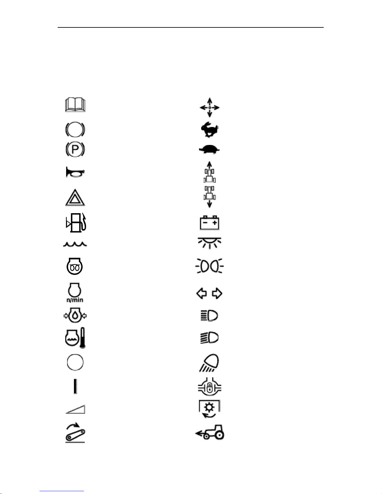
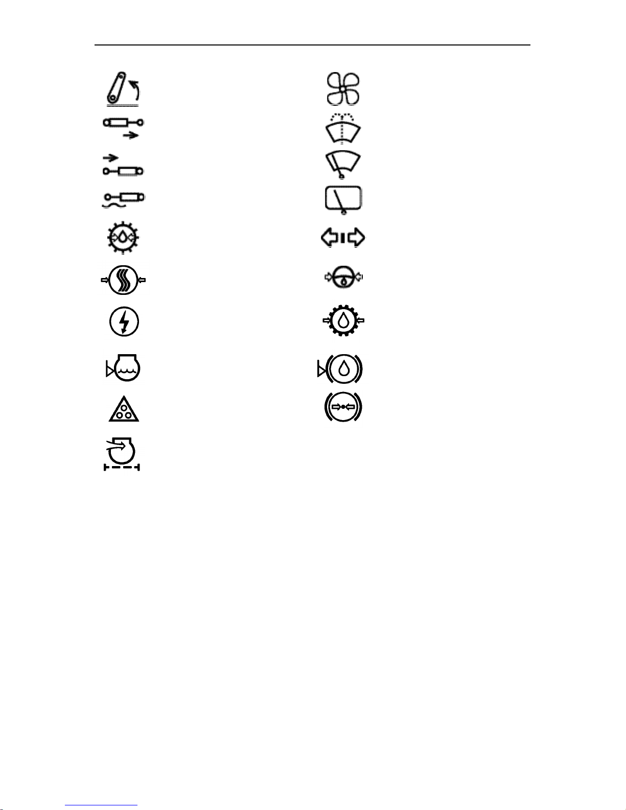
International Symbols
Manufacturer uses standard international symbols regarding instruments and operating controls.
Symbols with their meaning are given below.
— see operators manual
— control operating direction
— brake
— fast
— parking brake
— slow
— horn
— forward
— alarm signaling
— reverse
— fuel level in the tank
— battery charging condition
— coolant
— cab dome light
— starting preheater plug
— marker lights
— engine speed
— turning signals
— engine oil pressure
— headlights main beam
— engine coolant temperature
— headlights lower beam
— off/stop
— working headlights
— on/start
— differential lock
— continuous change
— PTO engaged
— lever — down
— FDA engaged
Page 7
БЕЛАРУС-1221.2/1221В.2/1221.3 Введение
6
— lever — up
— fan
— control valve spool “lift” posi-
tion
— windshield washer
— control valve spool “drop”
position
— front windscreen wiper
— control valve spool “float”
position
— rear windscreen wiper
— oil pressure in gearbox
— trailer turning signal
— air pressure in pneumatic
system
— oil pressure in HPS
— high voltage
— oil pressure in transmis-
sion
— coolant level
— brake fluid level
— trailer-train lights
— pressure in breaking
system
— air filter impurity
Page 8

BELARUS-1221.2/1221В.2/1221.3 Safety requirements
7
SAFETY REQUIREMENTS
Strict observance of safety precautions
and exact complying with the rules of
tractor control and its maintenance secure absolute safety of its operation.
General instructions
1. Study this operators manual attentively before operating the tractor.
Poor knowledge of the tractor operation and service may lead to accidents.
2. Only specially trained and skilled
operators, who have passed accident-prevention and fire safety
briefings, are allowed to operate the
tractor.
3. If tractor is equipped with safety
belt use it during the operation. If
tractor is not equipped with safety
belt, contact the dealer.
4. Do not take a passenger into the
cab, if additional seat and hand
rails are not installed. There is no
any other safe space for a passenger in the cab!
5. Keep all warning plates clean.
6. Replace any damaged or missing
warning plate.
7. Carefully inspect the tractor, trailed
machine, mounted implement and
hitch before commencement of operations. Before starting operations
make sure that they are in good
order. Trailed agricultural machines
and transport trailers should have
rigid hitches, preventing their swaying and rear-end collision with the
tractor during a hauling.
Safety measures during tractor operation
Warning! Do not ever start the en-
gine while being outside the operator’s workplace. Always stay in the
cab in the operators seat when starting the engine or operating the controls.
7. Before starting the engine, make
sure that the parking brake is applied, the PTO control lever is in
«Disengaged» position, the gearshift and range selector levers are
in «Neutral» position. Make sure
the gearbox pump drive shifter is in
«Engine-Driven» position.
8. Always stay in the operators seat
when starting the engine or operating the controls.
9. Before starting motion, warn the
people around and those working
on the trailed machines with the
horn.
10. Do not leave the tractor in motion.
11. Before leaving the cab do not fail to
disengage the PTO, stop the engine, apply parking brake and remove the switch key.
12. Do not operate the tractor indoors
without proper ventilation. The exhaust gases may cause fatal outcome!
Page 9

BELARUS-1221.2/1221В.2/1221.3 Safety requirements
8
13. Stop the tractor immediately if the
engine or steering system fails.
Remember, that with the engine
shut down you will have to apply
much more forces to the steering
wheel in order to control the tractor.
14. Do not work under raised agricultural implements. Do not leave
mounted implement in raised position during long-term stops.
15. If the tractor front part rises off the
ground when heavy implements are
mounted at the rear hitch linkage
mechanism, install the front ballast
weights.
16. When operating with front loader,
fill rear tires with liquid ballast and
adjust a maximum wheel turning
angle to 30° at the most with adjusting screw (20) fig. Д-25.
17. Before lifting or lowering a mounted
agricultural implement, and when
turning, make sure in advance
there is no danger of contact with
anyone around or interference with
some obstacle.
18. Cardan shaft, transmitting rotation
from the tractor PTO to the implements of the unit, should be fitted
with appropriate guards.
19. Make sure of proper mounting of
any additional equipment or auxiliary device and make sure they
are designed for use with your tractor.
Bear in mind that your tractor, when
improperly employed, may be dangerous both for you and for the
people around. Do not use implements, which are not designed for
installation on this tractor.
20. To prevent tractor roll-over, be
careful during the driving the tractor. Select a safe speed, corresponding to the road conditions, especially during cross-country driving, driving over ditches, slopes and
sharp turns.
21. When working on hillsides, increase
tractor wheel tread to maximum
width.
22. Avoid making sharp turns at full
load and at high travel speed.
23. When using the tractor for hauling
operations, follow the rules:
• Increase wheel tread to 1600 mm
(64’’) at least;
• Interlock the brake pedals, check
and, if necessary, adjust the
brakes for simultaneous action;
• Check the parking brake perfor-
mance;
• Check condition of the light and
audible signaling devices;
• Cargo trailers must be fitted with
rigid hitches as well as be connected with safety chain or rope;
• Never travel downhill “free wheel”
with transmission in neutral position or clutch disengaged. When
traveling downhill use the same
gear as you would when going
uphill;
• Never use a trailer without inde-
pendent brakes, if its gross weight
exceeds the half of the tractor total
actual mass. The faster you move
and the more load you tow, the
longer safety distance must be;
• Disengage the FDA to avoid ex-
tensive wearing out of drive components and tires;
• Do not use the RADL at speed
exceeding 10 km/h and while turning.
• Do not stop the tractor on the
slopes. If it’s necessary to stop,
Page 10

BELARUS-1221.2/1221В.2/1221.3 Safety requirements
9
engage the 1st gear and apply the
parking brake.
24. When you use PTO-driven equipment, stop the engine and make
sure that PTO drive end has
stopped completely, before you
leave the cab and uncouple the
equipment.
25. Do not wear loose clothes when
operating the PTO or when you are
in the vicinity of the rotating equipment.
26. When working with stationary machinery driven from the PTO, do not
fail to apply the parking brake and
block the rear wheels of the tractor
from the front and rear sides. Also
make sure the machine is secured
in its place.
27. Make sure the guard of the PTO
drive end is installed, and if the
PTO is not used, shift the PTO
mode control switch into midposition.
28. Do not carry out cleaning, adjustment and maintenance of the PTOdriven equipment when the engine
is running.
Safety measures during tractor
maintenance
29. Never refuel the tractor when the
engine is running.
30. Never smoke while refueling the
tractor.
31. Never fill the tank fully. Leave place
for fuel expansion.
32. Never add petrol or mixtures to the
diesel fuel. Such combinations may
enhance the fire or explosion hazard.
33. Use properly summer and winter
fuel grades. Fill in a fuel tank at the
end of each day to minimize night
water condensation.
34. Perform all operations, relating to
engine and tractor cleaning, prepa-
ration for work, maintenance, etc.,
when the engine is shut down and
brakes are applied.
35. The cooling system operates under
pressure, which is maintained by
the valve installed in the filler cap. It
is dangerous to remove the cap
when the engine is hot. To avoid
face and hands burns be careful
while opening radiator filler cap
when the engine is hot. Put close
cloth on the cap and take on a
glove in advance.
36. To avoid skin burns, be careful
when draining cooling liquid or water from the cooling system, hot oil
from the diesel, hydraulic system
and transmission.
37. Be careful when servicing storage
batteries, because electrolyte
causes burns if it comes into contact with the skin.
38. To avoid danger of explosion keep
any type of open flame away from
engine fuel system and storage batteries.
39. Keep the tractor, its equipment, especially brakes and steering control, in operable state in order to
ensure your own safety and safety
of people around.
40. Do not make any alternations in the
tractor or its separate components
without consulting your dealer and
or manufacturing works. Otherwise
the tractor will be deprived of aftersales service.
41. To avoid the fuel splash-out while
refueling the tractor by mechanized
method, remove the screen filter
from the fuel tank filler neck.
Screen filter is designed only for
manual refueling of the tractor in
the field.
42. Refuel the tractor using only oils
and lubricants recommended by the
manufacturing works. It is strictly
forbidden to use other lubricants!
Page 11

BELARUS-1221.2/1221В.2/1221.3 Safety requirements
10
Safety requirements during
operation and maintenance of
electrical equipment
44. To avoid damaging the semiconductor devices and resistors,
comply with the following precautions:
• Do not disconnect the storage bat-
tery while the engine is running.
This will cause a peak voltage in
charging circuit and lead to immediate damage to the diodes and
transistors;
• Do not disconnect electric wires
until the engine is stopped and
electric switches are in the “OFF”
position;
• Do not cause a short circuit by the
wrong connection of electrical
wires. A short circuit or reverse
polarity will cause damage to the
diodes and transistors;
• Do not connect a storage battery
into the electrical equipment system until it has been checked for
correct voltage and terminals polarity;
• Do not check for current flow by
means of spark test as it will immediately result in transistors
breakdown;
• It is prohibited to switch off the
battery disconnect switch when
the engine is running;
• It is prohibited to operate the trac-
tor without storage battery.
Hygienic requirements
• Daily fill the thermos with fresh
clean drinking water;
• First-aid kit should be completed
with bandages, iodine tincture, ammonia spirit, borated petrolatum, sodium
carbonate, menthol valerate and analgin;
• Use cab natural ventilation or cab
air heating and cooling unit according to
operation conditions.
• If the time of continuous tractor op-
eration during a work shift exceeds 2,5
hours it’s necessary to use personal
noise protection equipment according
to GOST 12.4.051-87 (earplugs, antiphons
Fire safety requirements
1. The tractor should be equipped with
firefighting equipment – shovel and
fire-extinguisher. It’s prohibited to
operate the tractor without fireextinguishing means.
2. Never refuel the tractor when the engine is running.
3. Do not smoke while refueling the
tractor.
4. Never fill the tank fully. Leave place
for fuel expansion.
5. Never add petrol or mixtures to the
diesel fuel. Such combinations may
enhance the fire or explosion hazard.
6. Places of tractors parking, storage of
fuel and lubrication materials should
be plowed around with a strip having
at least 3 m width and provided with
fire-extinguishing means.
7. Refuel the tractors with fuel and lubrication materials by mechanized
method with the engine shut down.
Use lighting at night. It is not recommended to fill in fuel tanks with the
help of buckets.
8. When performing repair operations in
the field with the application of electro-gas welding clean parts and assembly units from plant remains.
9. Prevent collector and muffler pollution with the dust, fuel, straw, etc.
10. Prevent straw reeling on the rotat-
ing parts of machines aggregated
with the tractor.
11. When washing parts and assembly
units with kerosene or gasoline take
Page 12

BELARUS-1221.2/1221В.2/1221.3 Safety requirements
11
measures to prevent the flaming of
the washing liquid fumes.
12. Do not operate the tractor in the fire
dangerous areas when the bonnet
and other guard devices are taken
off the engine heated parts.
13. Do not use open fire for heating up
the oil in the engine pan, when filling in fuel tanks, and for burning off
the contaminant pollution of the radiator core.
14. When the fire seat occurs cover it
with sand or with canvas cloth or
other close cloth. Use the carbondioxide fire extinguisher. Do not extinguish burning fuel with water
15. See that there are no flammable
materials near exhaust manifold
and muffler when the engine is running.
Page 13
BELARUS-1221.2/1221В.2/1221.3 Technical data
12
TECHNICAL DATA
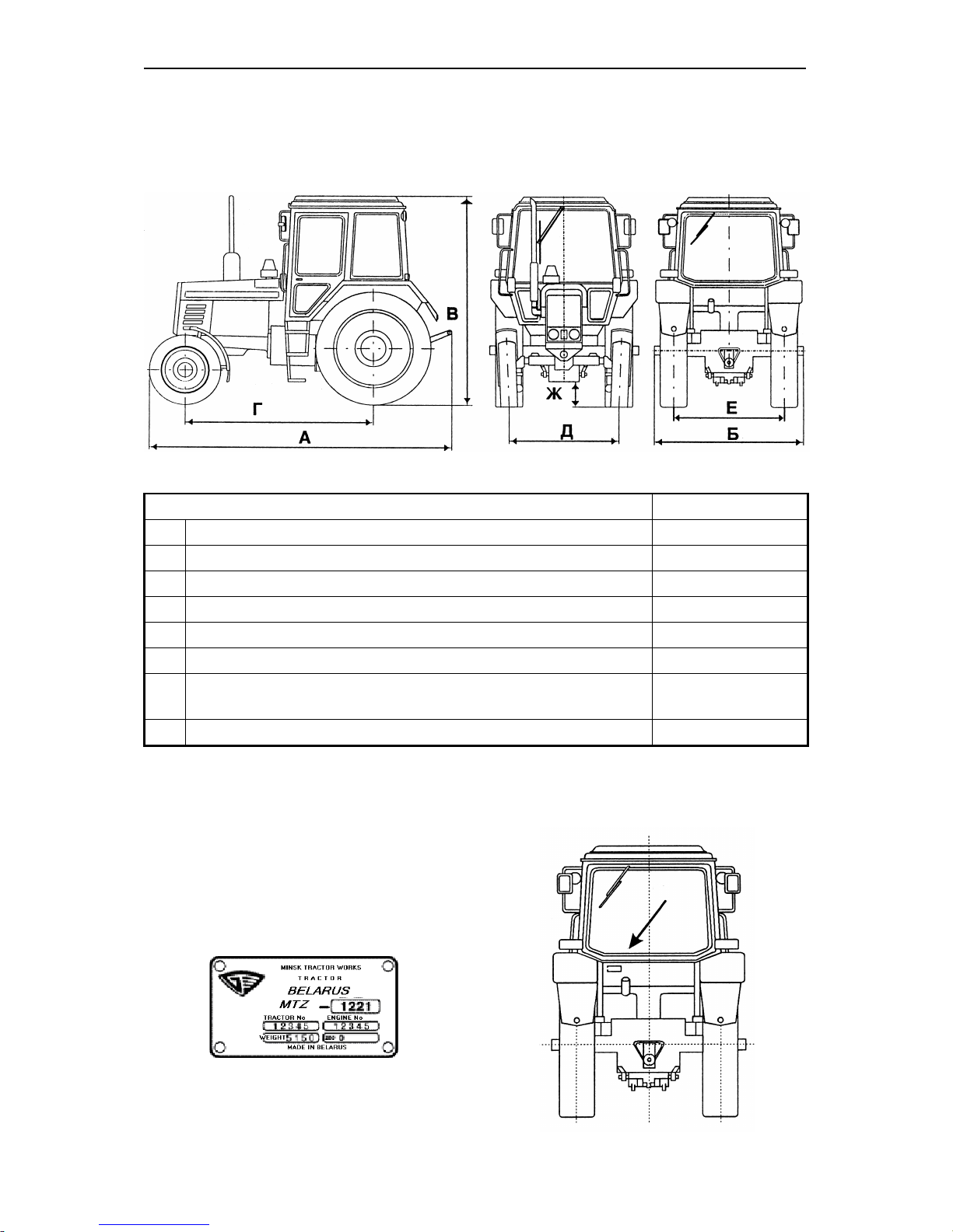
Weights and dimensions
Designation
Value
А
Length, mm (with loads)
4500±40
Б
Width, mm
2300±10
В
Height, mm
2850±50
Г
Wheelbase, mm
2760±30
Д
Front track width, mm
1540...2090
Е
Rear track width, mm
1530...2150
Ж
Ground axles under axle tubes, mm
(not less than)
620
Operating weight (as shipped from plant), kg
5370±100
Identification numbers of tractor constituents
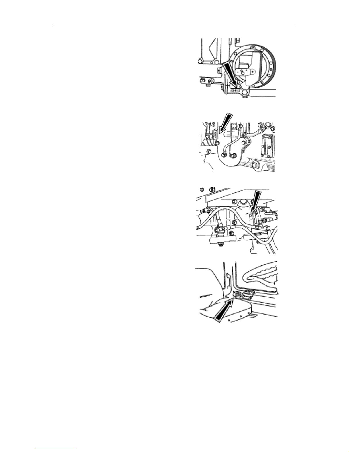
Tractor identification plate indicates tractor serial number and engine serial number.
Page 14
BELARUS-1221.2/1221В.2/1221.3 Technical data
13
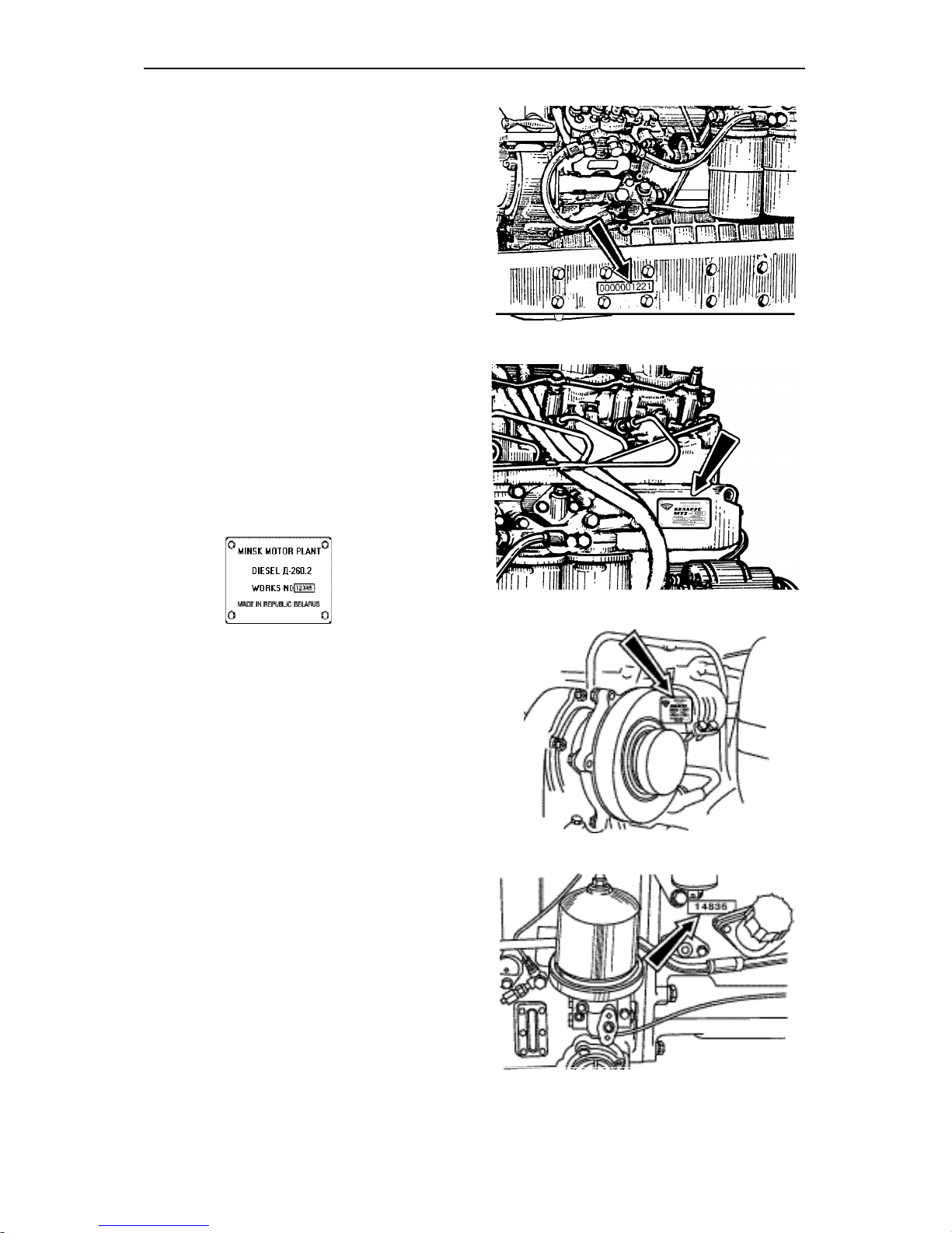
Tractor serial number is duplicated on
the right sidemember and on the plate of
right and left sidemembers.
Engine serial number is also indicated on
the engine identification plate located on
the left side of cylinders block
Engine turbocharger identification
number
Clutch coupling identification number
Page 15
BELARUS-1221.2/1221В.2/1221.3 Technical data
14
Gearbox identification number
Transmission identification number
Front driving axle identification number
Cab serial number and OECD certificate
number
Page 16

BELARUS-1221.2/1221В.2/1221.3 Technical data
15
Engine
Engine model
Д-260.2 or Д-260.2С
Д-260.2S2
Make
MMP (Minsk motor plant)
MMP (Minsk motor plant)
Type six-cylinder, in-line six-cylinder, in-line
Cycle 4 stroke 4 stroke
Fuel injection system direct injection direct injection
Compression ratio (calculated)
16
17
Cylinder bore
110 mm
110 mm
Piston stroke
125 mm
125 mm
Displacement
7,12 l
7,12 l
Firing order
1-5-3-6-2-4
1-5-3-6-2-4
Engine aspiration turbo-charged turbo-charged
Cooling system liquid liquid
Rated speed
2100 rev/min
2100 rev/min
Maximum no-load speed
2275 rev/min
2270 rev/min
Minimum idle speed
800±50 rev/min
800±50 rev/min
Rated power
98,0±2,0 kW
100±2,0 kW
Peak torque
520 N∙m
559 N∙m
Fuel rate
235±11,8 g/kW∙h
240±12 g/kW∙h
Engine weight (dry)
650 kg
710 kg
Page 17

BELARUS-1221.2/1221В.2/1221.3 Technical data
16
Engine fuel system
Fuel pump
Type: six-plunger, in-line with priming
pump: PP6M10P1f-3492 «MOTORPAL»
(Czechia) or 363.1111003-40.03 «YAZDA» (Russia).
Regulator: mechanical, variable speed,
with fuel supply corrector, automatic engine fuel feed, smoke suppression
Injector ФДМ-22 with five-hole closed-
type atomizer.
Pressure at the beginning of fuel injection
— 21,6…22,4 MPa (220…228 kgf/cm2).
Fuel injection advance angle till UDC
— 22°±1°.
Air cleaner
Type: Dry with three-stage cleaning,
changeable paper filter element and
clogging indicator.
Filter elements: paper filters – elements
made of highly porous paperboard.
Turbocharger: ТКР-7 type, radial inward
turbine and radial-flow compressor, assembled on one shaft.
Installation of foreign producers turbochargers is possible.
Engine cooling system
Type: Pressurized liquid cooling system
with automatic temperature control by
friction clutch and two thermostats.
Oil cooling: by oil-to-water heat exchanger, built into cylinder block.
Normal operating temperature
from 80°C to 97°C. Cooling system capaci-
ty: 24 L
Engine lubrication system
Type: Combined, with oil-to-water heat
exchanger built into cylinders block.
Oil filters: centrifugal filter and filter with
changeable paper filter element.
Oil pressure at minimum speed – 0.08
MPa (0.8 kgf/cm2), at rated speed–
0.28…0.45 MPa (2.8…4.5 kgf/cm2),
Lubrication system capacity — 22 l.,
including engine crank case— 18 l.
Oil system capacity — 22 l, including
engine crank case — 18 l.
Engine Starting System
24 V starting motor
Starting aid:
Heating plugs (for tractors “BELARUS-
1221.3”)
Clutch coupling
Type: Dry friction, double-disk, with tan-
gential suspension of pressure disk.
Disk diameter: 340 mm.
Page 18
BELARUS-1221.2/1221В.2/1221.3 Technical data
17
Gearbox
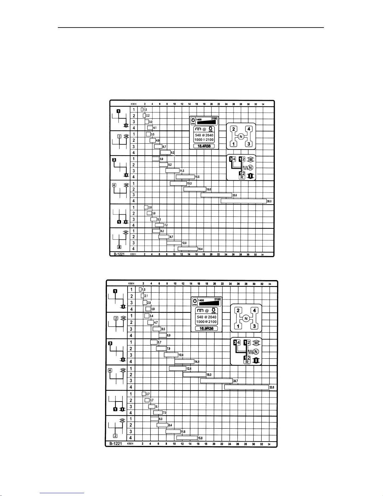
1. Type: 16/8, mechanical, step-wise, range. It provides with 16 forward gears and 8
reverse gears
Tractor design travel speeds in km/h
(GB 16/8, tyres 18,4R38)
Tractor design travel speeds in km/h
(GB 16/8, tyres 16,9R38)
Page 19
BELARUS-1221.2/1221В.2/1221.3 Technical data
18
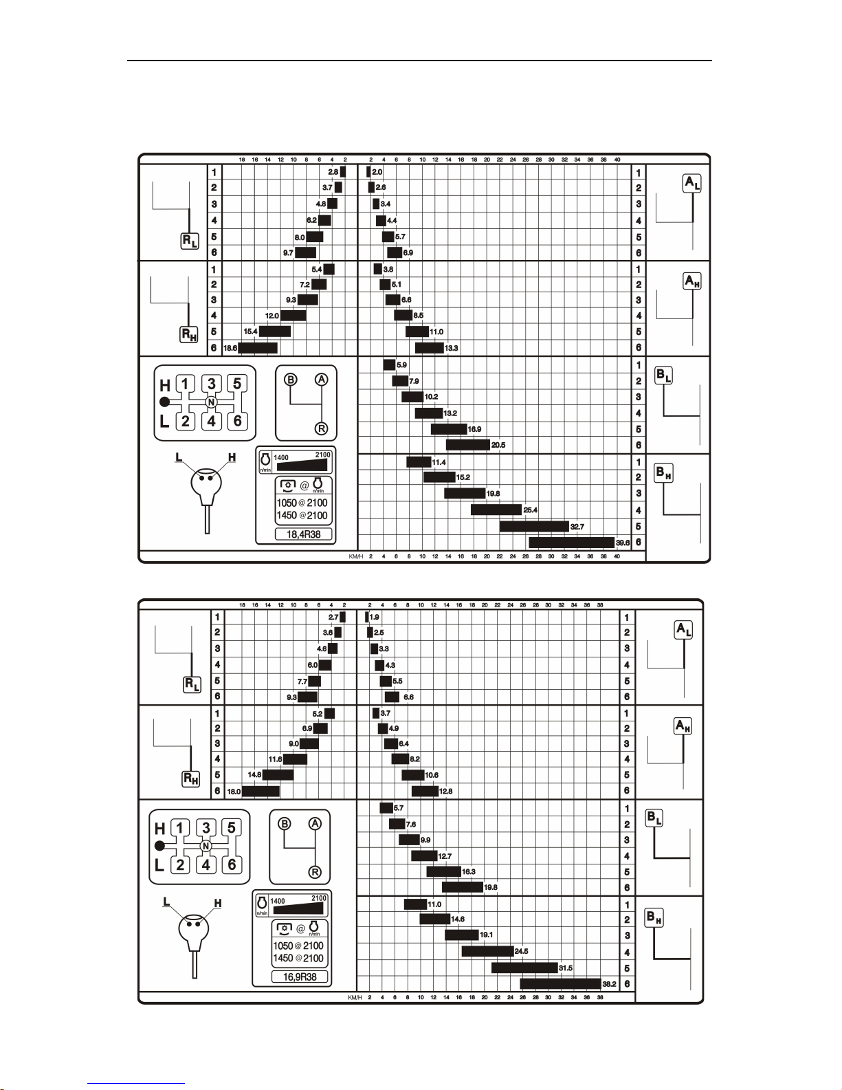
2. Type: 24/12, 16/8, mechanical, step-wise, range. It provides with 24 forward gears
and 12 reverse gears.
Tractor design travel speeds in km/h (GB 24/12, tyres 18,4R38)
Tractor design travel speeds in km/h (GB 24/12, tyres 16,9R38)
Page 20

BELARUS-1221.2/1221В.2/1221.3 Technical data
19
Rear axle
Main gear: a pair of bevel gears with
spiral tooth.
Final drives: a pair of spur gears for
each sideboard.
Rear-axle drives: planetary type.
Differential lock: Oil-actuated friction
clutch
Brakes
Service Brakes: on rear wheels: twodisk or three-disk, dry with mechanical
servo drive. Disk diameter: 204 mm (or
eight-disk, operating in oil sump (on
order))
Parking brake: On rear wheels
through differential lock on final drives
and rear-axle drives. Dry-disk type with
mechanical hand control. Disk diameter: 180 mm (or 4-disk, operating in oil
sump (on order))
Front driving axle
Type: two-point, portal
Main gear type: bevel gears with spir-
al tooth.
Differential type: self-locking, exces-
sive friction
Final gears type: planetary
Drive gear type: built in GB single pa-
rallel-shaft reduction gear unit with hydraulically operated multiplate clutch;
cardan shaft.
Hydraulic distributor of FDA control:
hydraulically operated, spool-type,
electrically controlled
PTO drive
Type: independent, two-speed and
synchronous
Drive clutch: Planetary reduction gear
with band brakes
Drive: Mechanical, by lever on control
panel
PTO end speed:
Independent drive
I — 540 rpm; N=60 kW (82 h. p.),
II — 1000 rpm; N=90 kW (123 h. p.)
Synchronous drive
4,36 rev/meter of travel when fitted
with tires 16,9R38.
4,17 rev/meter of travel when fitted
with tires 18,4R38.
Output shaft: SAE standard 6-spline
for 540 rpm and 21-spline for 1000
rpm.
Rotation: Clockwise
Steering
Type: hydrostatic (H.S.).
Feed pump: NSH14, gear-type, left-
handed rotation.
Volume constant — 14-16 сm3/rev.
Metering pump type — gerotor type
models: Danfoss; Rexroth Hydraulic;
Lifam.
Volume constant – 160 сm3/rev.
Relief valve pressure— 14 МPa (140
kgf/сm2).
Antishock valves pressure — 20 МPa
(200 kgf/сm2).
Actuating mechanism: two hydraulic
bilateral cylinders.
Bore — 50 mm,
Cylinder stroke— 200 mm
Steering wheel range of adjustment:
• in angle of slope - from 40° to 25°
with fixation on every 5°,
• in height – within the range of 100
mm.
Backlash in the steering wheel not
less than 25°.
Page 21

BELARUS-1221.2/1221В.2/1221.3 Technical data
20
Hydraulic lift linkage (HLL)
Type: unit-principle with hydraulic lift
device (with two plunger cylinders) It
provides 4 control modes of agricultural implements position:
• height control mode;
• power control mode;
• position control mode;
• combined (mixed) control mode.
Outlets: 3 pairs and one drain line
(rear).
Oil feed pump
Тype: gear-type. Pump capacity — not
less than 56 l/min at 2100 rpm.
Distributive valve: hydraulic spooltype РП70-1221 or RS-213 «MITA», 3section with fixation of spools in “float”
position. It has the following positions:
“Up”, “Neutral”, “Down” and “Float”.
Hydraulic lift distributor:
820-4634010. hydraulic spool distributor
Cylinder: piston cylinder
(2 pcs.) — bore 90 mm,
stroke — 220 mm.
Rear mounting unit:
Type: swinging four-bar linkage of cat-
egory II
Lifting capacity: at distance of 610
mm from lower links balls — 35kN (3500
kgf)
Electrical equipment
Voltage: 12V
Power system: two 12 V accumulator
batteries, with capacity 120 А•h.
Alternator with built-in rectifier and
regulator, power 1150 Wt.
Lighting and light alarm system:
• front driving lights with high/low
beam;
• front and rear work lights;
• front and rear lamps;
• dash board light and rear registra-
tion plate light;
• hazard warning lights;
• lights of “road-train” sign.
Power consumers connection: 9contact composite plug.
Dash board, electrical tachospeedometer and control lamp units.
Heating plugs (for “BELARUS-
1221.3” tractors):
Nominal voltage 24V
Other equipment:
Front and rear window wipers; windshield washer; dome light.
Pneumatic system
Compressor
Type: single-cylinder, air-cooled
Trailer brakes control
Type: pneumatic, single-wire, locked
with tractor service brakes.
Tires
Front:
Main: 420/70R24 or 14,9R24;
On order: 11.2R24.
Rear:
Main: 18,4R38;
On order: 16.9R38, 11.2R42.
Wheel Track:
• front wheel track 1540...2090 mm,
• rear wheel track 1530...2150 mm.
Page 22
BELARUS-1221.2/1221В.2/1221.3 Operating controls and instruments
21
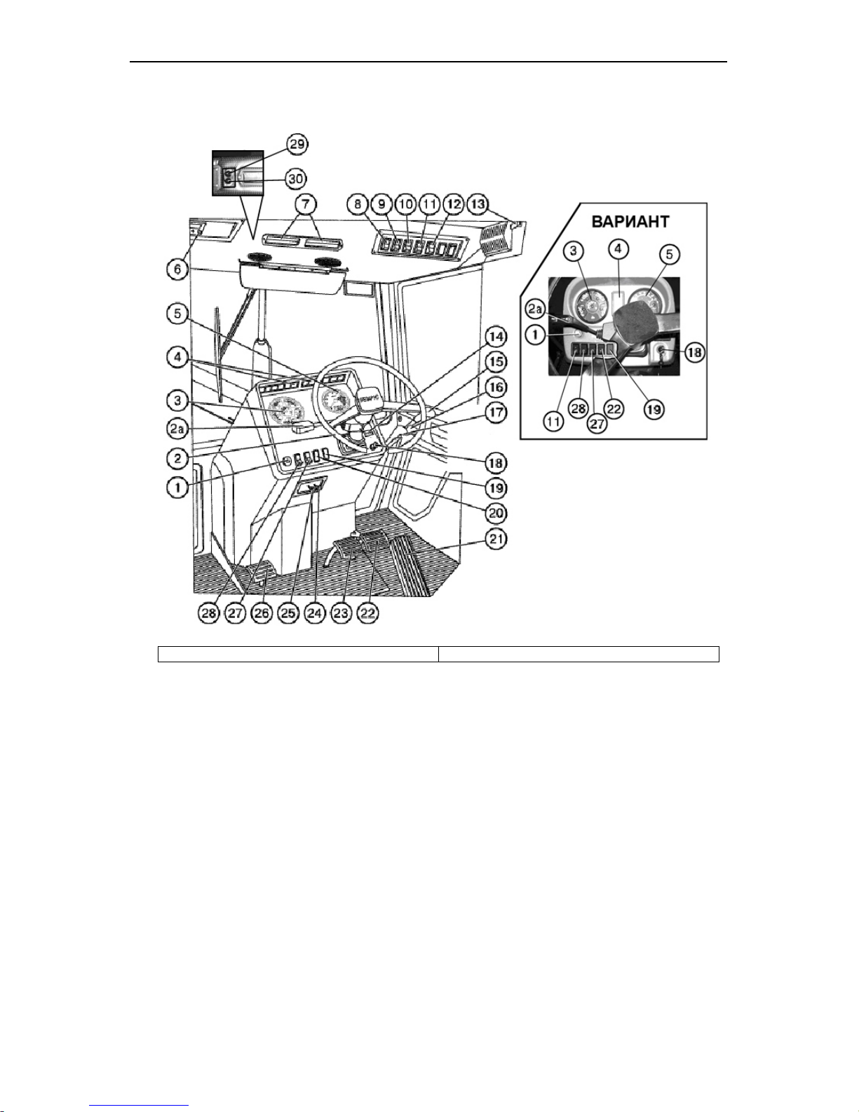
OPERATING CONTROLS AND INSTRUMENTS
ВАРИАНТ
VARIANT
1. Hazard warning lights switch
2. Steering wheel
2а. Switch located under steering wheel
3. Dash board
4. Warning lights blocks
5. Electrical tachospeedometer
6. Panel for electrical equipment installation
7. Air recirculating shutters
8. Windshield wiper switch
9. Cab ventilating and heating systems switch
10. Rear work lights switch
11. Front work lights switch
12. Switch of “road-train” sign lights
13. Cab dome light switch
14. Tachospeedometer programming unit (5)
15. Control lever of hydraulic system right rear
outlets
16. Control lever of hydraulic system right side
outlets
17. Control lever of hydraulic system left rear
outlets
.
18. Instruments and starter switch
19. Blind plug
20. Blind plug. Battery disconnect switch for
tractor BELARUS-1221В.2
21. Gas pedal
22. Right brake pedal
23. Left brake pedal
24. Steering column tilt control
25. Engine stop lever (when engine completed
with double-lever fuel pump „Motorpal“
(Czechia) or JSC «YAZDA» (Russia)
26. Clutch pedal
27. Windshield washer switch
28. Lights switch
29. Conditioner switch and refrigerating output
adjustment (if conditioner is installed)
30. Switch of air consumption adjustment (if the
conditioner is installed)
Page 23
BELARUS-1221.2/1221В.2/1221.3 Operating controls and instruments
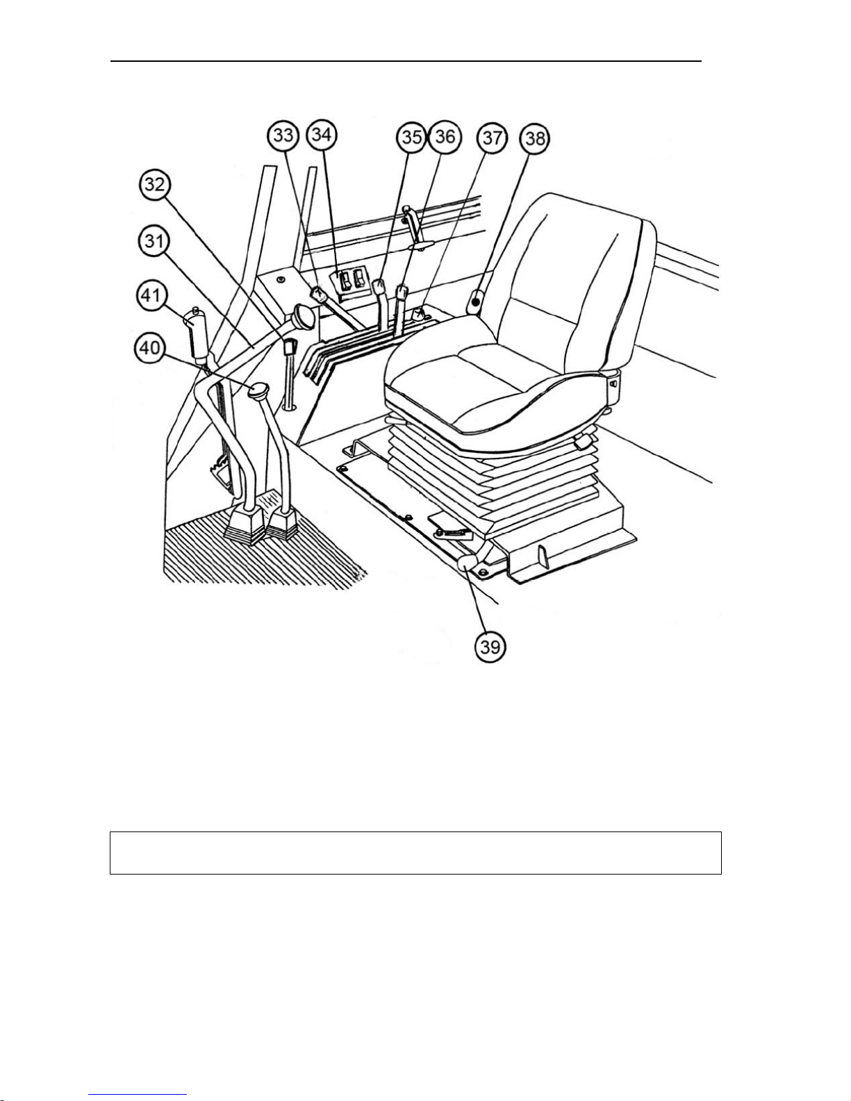
22
31. Range Shift Lever
32. PTO control lever
33. Fuel delivery control lever
34. FDA and rear axle differential lock control
unit
35. Position control lever
36. Draft control lever
37. Stop of position control lever
38. Battery disconnect switch
39. PTO shift lever (independent
- synchronous)
40. Ranges shift lever
41. Parking brake lever
Important: Before operating tractor for the first time, study all of the controls and instrument locations and their functions.
The given information will help you to study the controls and instruments so that the
tractor may be operated safely.
Page 24
BELARUS-1221.2/1221В.2/1221.3 Operating controls and instruments
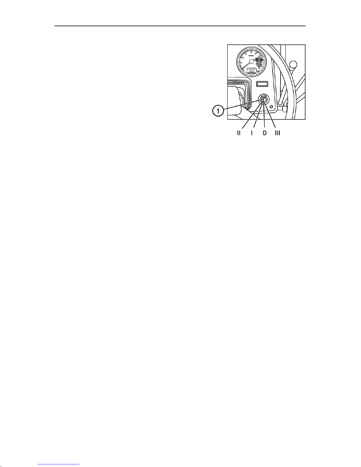
23
Starter and instruments switch (1)
The switch (3) has 4 positions:
• 0 — “Off”;
• I — “Instruments, control lamps unit, radio
equipment power supply “On”
• II — “Starter “On” (non-fixed position);
• III — «Radio power supply when the engine is
stopped»
Page 25
BELARUS-1221.2/1221В.2/1221.3 Operating controls and instruments
24
1. Instrument board
The scheme of the instruments dashboard 80-3805010-Д1 and 826-3805010 is given in
the section “Appendix”.
The instrumentation includes:
- instruments combination (Р2) with sensors;
- the electric tachospeedometer (Р1) with the control board (А3) and sensors;
- the electric light and audible alarms combined into two pilot lamp units (HG1 and
HG2) with the instruments dashboard 80-3805010-Д1 or into the pilot lamp unit and meter combined with the instruments dashboard 826-3805010.
To switch on the instruments, turn the starter and instrumentation switch key to the “I”
position. Then the voltage will be applied to the terminal “K3” of the switch, then to the
relay of instruments power supply, to the fuse (F2) of the unit and further – to the units
(HG1 and HG2), tachospeedometer (Р1), alarm device (НА2), combination meter (Р1)
and speed sensors (BV1 and BV2).
The instruments pointers shall move to the zero position of the scale or to the position
corresponding to the true value of the parameter controlled by the system at the moment.
In case of deviation of instruments readings from their true values, detect the cause of
the fault following the recommendations below.
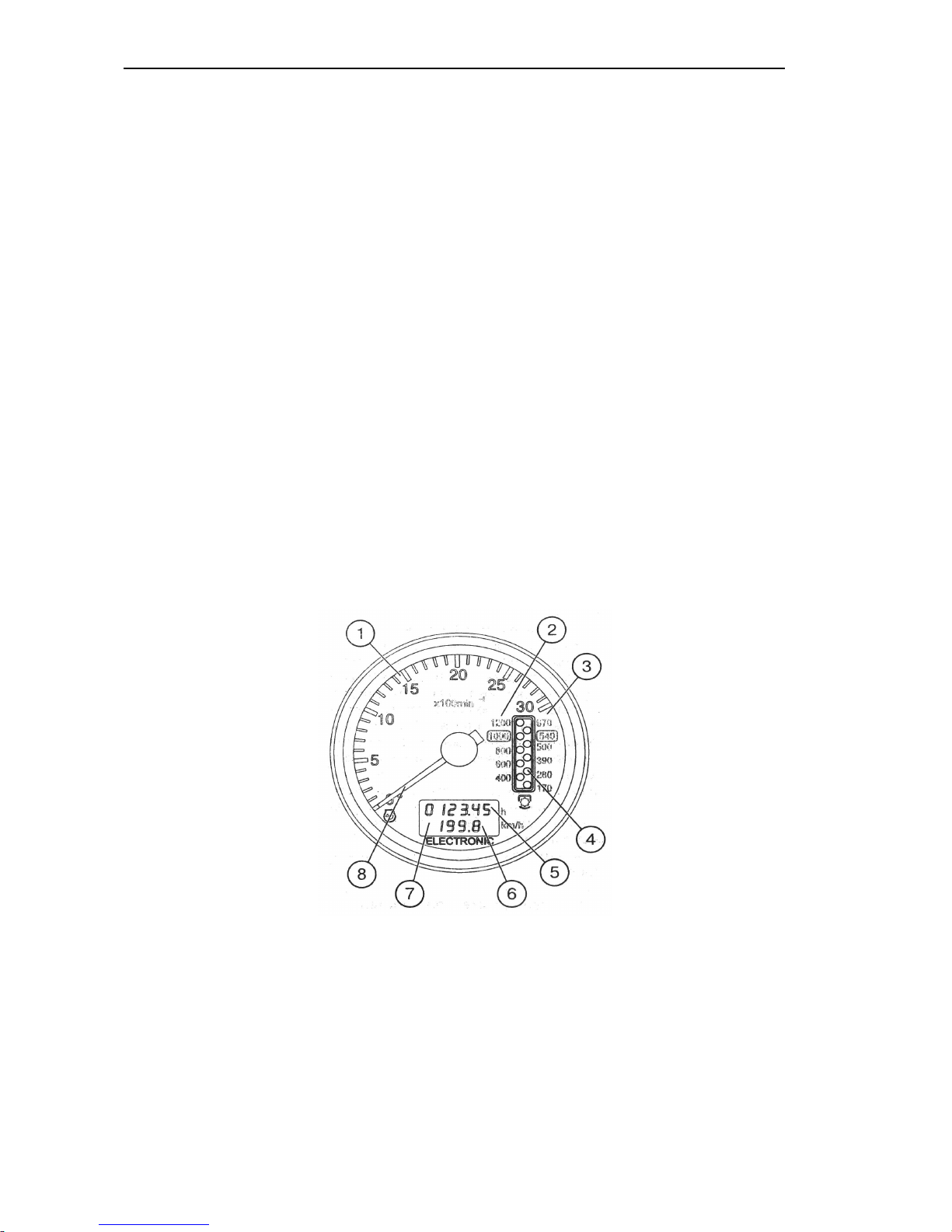
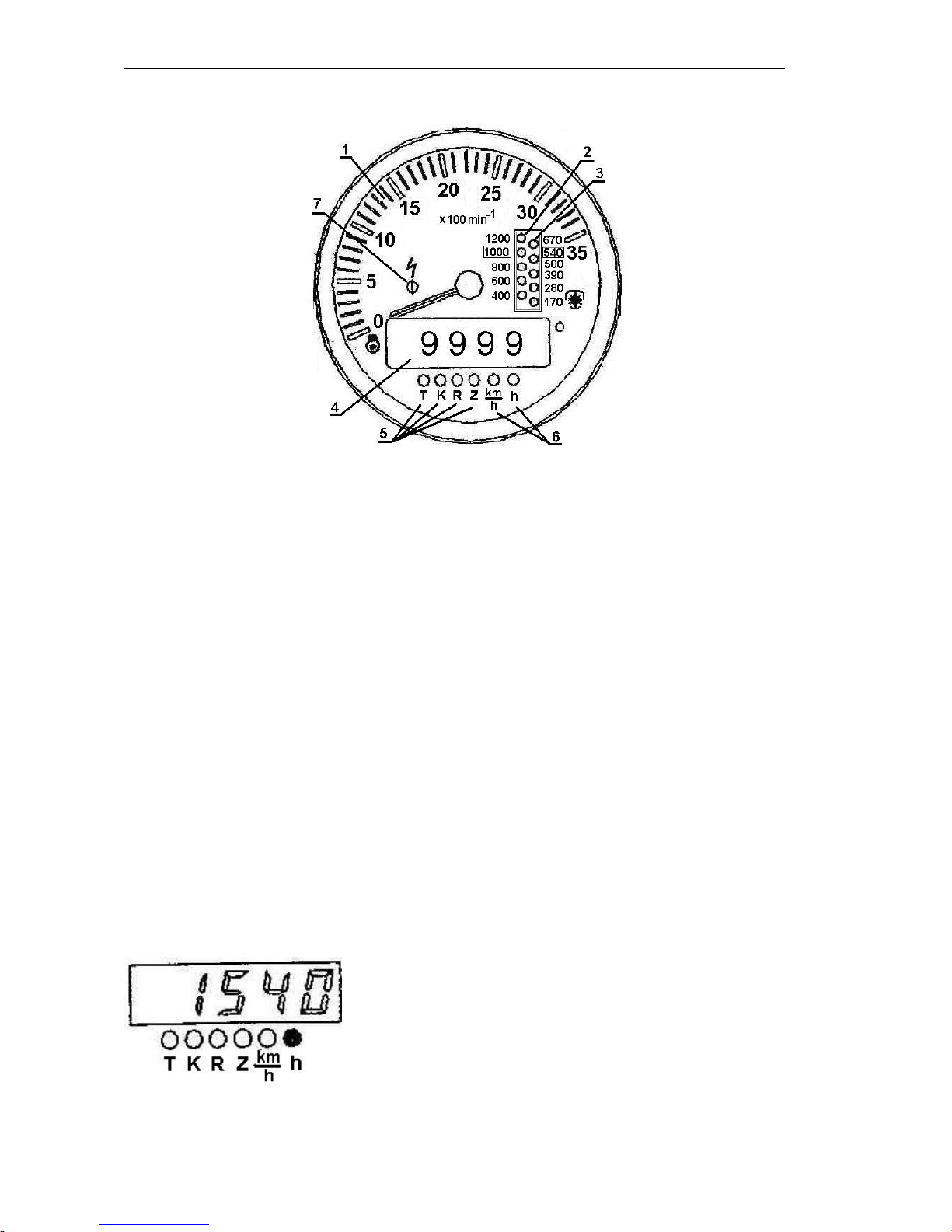
1.1 Tachospeedometer АР70.3813 (Fig. 1)
Рис. 1. Tachospeedometer (Р1):
1. Engine crankshaft rotational speed scale, rpm.
2. PTO II rotational speed scale –1000 rpm.
3. PTO I rotational speed scale –540 rpm.
4. PTO rotational speed display (LED).
5. Engine running hours indication, h.
6. Tractor speed indication, km/h.
7. Display of engine running hours and tractor speed (LCD)
8. Pointer indicator of the engine crankshaft speed
Page 26
BELARUS-1221.2/1221В.2/1221.3 Operating controls and instruments
25
The electric tachospeedometer installed in the dashboard operates as follows:
• on setting the starter and instrument switch in position “I” when the tractor is stopped,
the display (7) shows the engine running hours (5);
• when the tractor is moving, the display (7) shows the tractor speed indication (6)
(km/h), while the indication (5) disappears. The electric signal of the speed comes from
the speed sensors mounted on the rear axle cover (BV1, BV2). The speed readings are
taken through a signal from the sensor mounted on the pinion of the final drive of the
wheel rotating at lesser speed. The calculated speed is higher than the actual one, because no tractor skid is the taken into account;
• on starting the engine, the pointer indicator (8) moves round the index dial (1) to display the rotational speed of the engine crankshaft. At the same time, the display (4)
shows the PTO speed indication (rpm). The scale (3) is assigned to the PTO I and the
scale (2) – to the PTO II. The electric signal of the rotational speed is taken from the
phase winding of the alternator.
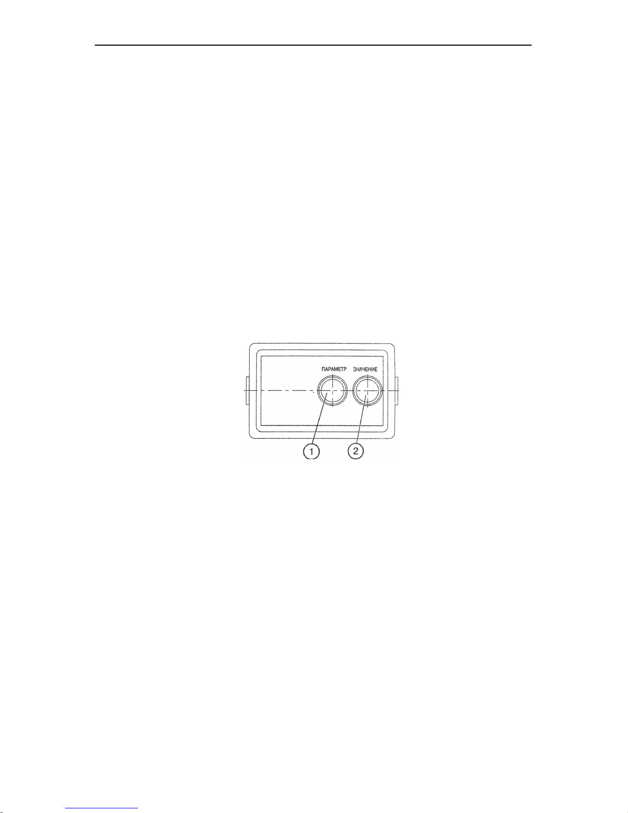
1.2. Tachospeedometer control board (Fig. 2)
The control board is installed in the instruments dashboard and serves for programming
the tachospeedometer to the specific model of the Belarus tractor.
Fig. 2. Control board (А3):
1. Button for setting the tachospeedometer to the programming mode and selecting the
programming parameter on the tachospeedometer display (7).2. Button for selecting the
value of the coded parameter shown on the display (7)
1.3 Programming the tachospeedometer АР70.3813
ATTENTION! The tachospeedometer has been programmed just to your tractor model
at the factory. Re-programming is required only in case of tyre type changing. Do not reprogram the tachospeedometer, if not necessary.
The tachospeedometer shall be programmed to ensure the correct display of the following tractor’s parameters: engine rotational speed, tractor motion speed and PTO rotational speed (540 and 1000).
Programming procedure:
– remove the control unit cover;
– press the button (1) to enter the programming mode (Fig. 2).
1. To ensure the correct display of the tractor motion speed, it is necessary to program
the tachospeedometer to the number of teeth of the pinion at the place of installation of
Page 27
BELARUS-1221.2/1221В.2/1221.3 Operating controls and instruments
26
the speed sensors (parameter “Z”) and rear wheel rolling radius (parameter “R”). To do
this:
– press the button (1) of the board and call the parameters “Z” and “R” in turn to the display (3) of the tachospeedometer (4);
– press the button (2) of the board and set the number of teeth (Z) according to Table 1
and value Rk according to Table 2:
Table 1
Number of teeth
(Z)
Tractor model
54 (56)* “BELARUS-1221” and modifications
* With driven gear 1522-2407122
Table 2
Tyre mark 18,4R38
Rk, m 0,829
Number coded 830
3. To ensure the correct display of the engine and PTO rotational speeds (540 and
1000), program the engine model (parameter “D”):
– press the button (1) and call the parameter “D” to the tachospeedometer display (3);
– press the button (3) and set the necessary engine model according to Table 3:
Table 3
Engine model Д-260.2 Д-260.2С Д-260.2S2
Rated
rotational speed, rpm
2100 2100 2100
Number programmed 260. 2C 260. 2C 260. 2C
On the expiry of seven seconds after programming, the instrument returns automatically
to the operating mode. Refit the board cover.
Note: If no information on the type of the tyre fitted is available, it is allowed to measure
the value Rk as a distance from the wheel axis to the ground prior to beginning the operation of the tractor.
1.4. Connecting the tachospeedometer
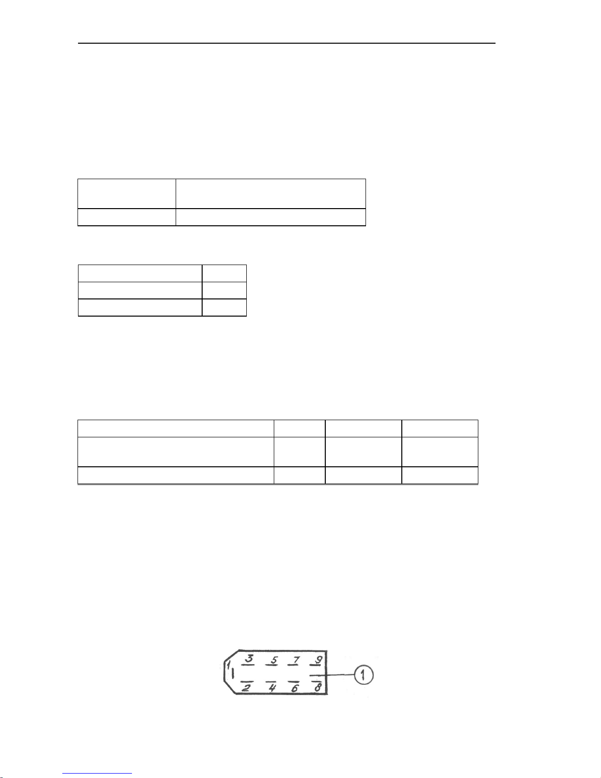
To connect the tachospeedometer to the instrumentation system, a 9-contact block is
provided on the rear panel of the instrument (Fig. 3).
Fig. 3.
Page 28

BELARUS-1221.2/1221В.2/1221.3 Operating controls and instruments
27
The identification of the block outputs is given in Table 4.
Table 4
Output Identification
1
to the terminal “–“
2
to the power supply unit “+12В”
3
to the board output “Parameter selection”
4
to the board output “Parameter value”
5
to the board output “Mode”
6
to the speed sensor BV2 (left wheel)
7
to the speed sensor BV1 (right wheel)
8
to the phase winding “W” of the alternator
9
to the instrument backlight lamps
1.5. Tachospeedometer diagnostics and troubleshooting
1. No instrument backlight:
Check the power supply wire connected to the output “9” of the 9-contact block of the
instrument (Fig. 3) – check if the backlight lamps are intact.
2. Jerking and jumps of the pointer of the engine rotational speed indicator over
the dial: poor contact on the alternator terminal and, therefore, poor signal from the
phase winding of the alternator. Repair.
3. Jerking of the pointer and understating the reading of the engine rotational
speed:
- Check and adjust the tension of the alternator driving belt.
4. Over- or understated readings of the engine and PTO’s rotational speeds (with
the nominal movement of the pointer):
- Check the correctness of programming the instrument according to the engine model
(parameter “D”): (see item 1.3);
5. The counter of astronomical hours of the engine running fails to accumulate
the operating time: Check the connection of the wire to the contact “8” of the instru-
ment block and the presence of the frequency signal from the phase winding of the alternator.
6. Over- or understated readings of the tractor speed:
- Check the correctness of the instrument programming according to the rolling radius of
the rear wheels (Rk) (see item 1.3);
- Check the correctness of the programming according to the number of teeth of the
half-axle pinion (Z) (see item 1.3).
7. No readings of the tractor motion speed: Check the presence of signals from both
the speed sensors (BV1, BV2).
8. The readings “02…07” km/h appear on the instrument indicator when the tractor is moving:
- the numbers “02…07” and, 12 seconds later, “0” appear from the right side of the
scale – no signal from the right speed sensor (BV1).
- the numbers “02…07” and then “0” appear from the left side of the scale – no signal
from the left speed sensor (BV2).
Page 29
BELARUS-1221.2/1221В.2/1221.3 Operating controls and instruments
28
1.6. Combined indicator КД 8083
Fig. 4. Tachospeedometer (Р1):
1 – Engine rotational speed indicator (pointer indicator).
2 – PTO 1000 rotational speed scale (opposite to the respective value of the PTO
rotational speed).
3 – PTO 540 rotational speed scale (opposite to the respective value of the PTO ro-
tational speed).
4 – Five-digit indicator.
5 – LED’s lighting up in the mode of programming the coefficients “K”, “R” and “Z”
(opposite to the respective LED).
6 – LED’s lighting up in the mode of display of the motion speed “km/h” and total en-
gine running time “h” (opposite to the respective LED).
7 – Alarm of the overvoltage in the tractor on-board power system (red) operates, if
the voltage exceeds 18.5 V.
In this case the instrument is switched off because the protective device operates. Should the voltage
drop down to 16.5 V, the indicator returns to the operating state and the overvoltage indicator goes out.
Indicator operating procedure
On switching on the power supply, the indicator is switched to the main operating
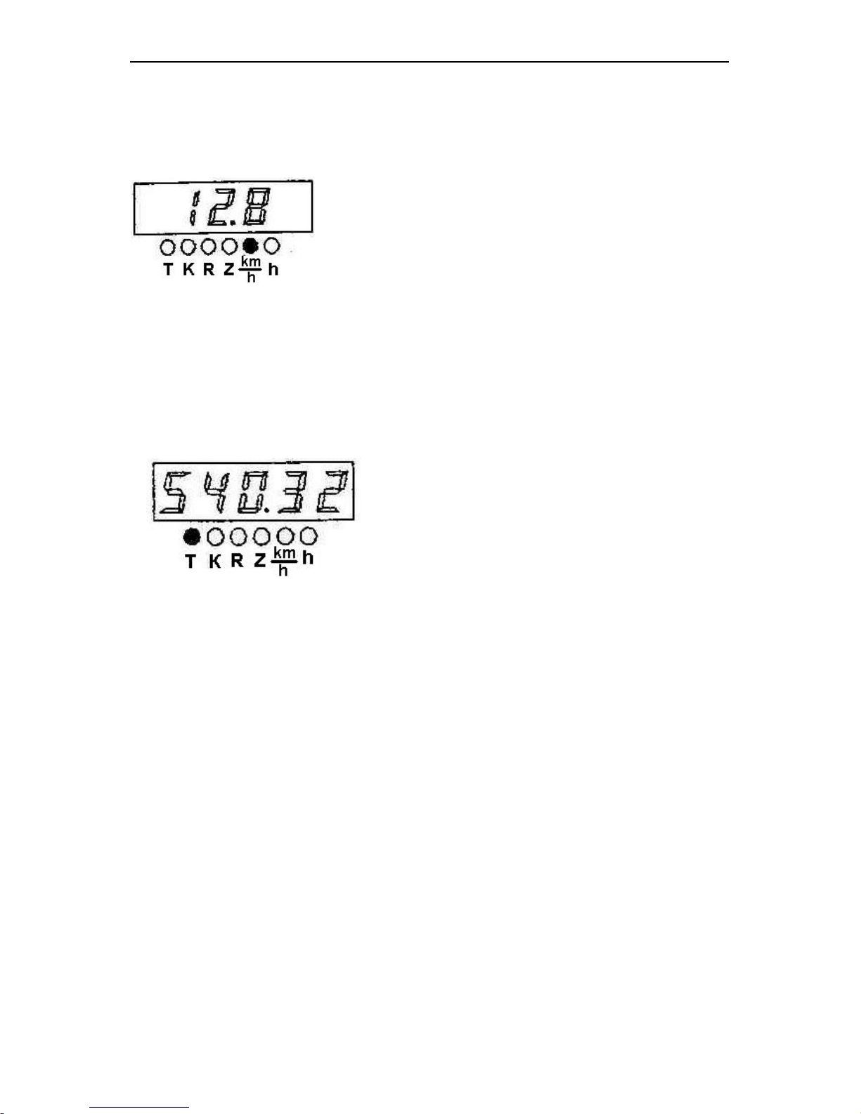
mode. In case of absence of signals from the speed sensors the digital indicator (4)
shows the reading of the total engine running time and the LED located next to the
symbol “h” lights up.
Total engine running time:
Appearance of the pulses from the speed sensors at the input of the pulse indicator
causes the switching-on to the motion speed indication mode. Then the measured
Page 30
BELARUS-1221.2/1221В.2/1221.3 Operating controls and instruments
29
calculated speed reading is shown on the digital indicator and the LED located next to the
symbol “km/h” lights up.
The calculated motion speed (km/h).
1.7 Programming the indicator КД8083
Programming procedure:
- remove the control board cover;
- press the button (1) of the control panel and hold it down for at least 2 seconds;
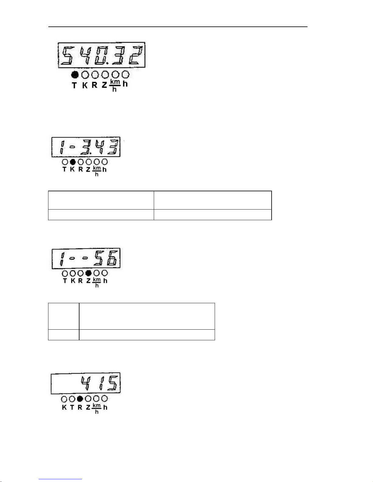
- the display (7) shows the mode “Adjusted total engine running time”. In this case, the
LED located next to the symbol “Т” lights up.
- press repeatedly the button (1) to switch over cyclically the programmable parameters;
- press the button “2” to enter the required value of the selected parameter, then the
least significant digit (the first on the right) of the selected parameter of the indicator
starts blinking with the period of 0.3 s;
- set the required value of the less significant digit of the selected parameter by pressing
the button “2”;
- press shortly the button “1”; then the second from the right digit of the digital indicator
shall start blinking;
- set the required value in the second from the right digit of the parameter to be corrected by pressing the button “2”;
- press shortly the button “1”; then the third from the right digit of the digital indicator
shall start blinking;
- pressing the button “2” set the required value in the third from the right digit of the parameter to be corrected
- fix the entered value of the parameter by pressing the button “1”;
- on pressing the button “1” next time, the switching to the next parameter will occur.
To exit the programming mode, enter the adjusted time mode, press and hold down the
button (2) for at least 2 s; then the readings “8.8.8.8.8” shall be shown in the five-digit
indicator for 1-4 seconds and all the LEDs of the PTO’s scales shall light up.
Page 31
BELARUS-1221.2/1221В.2/1221.3 Operating controls and instruments
30
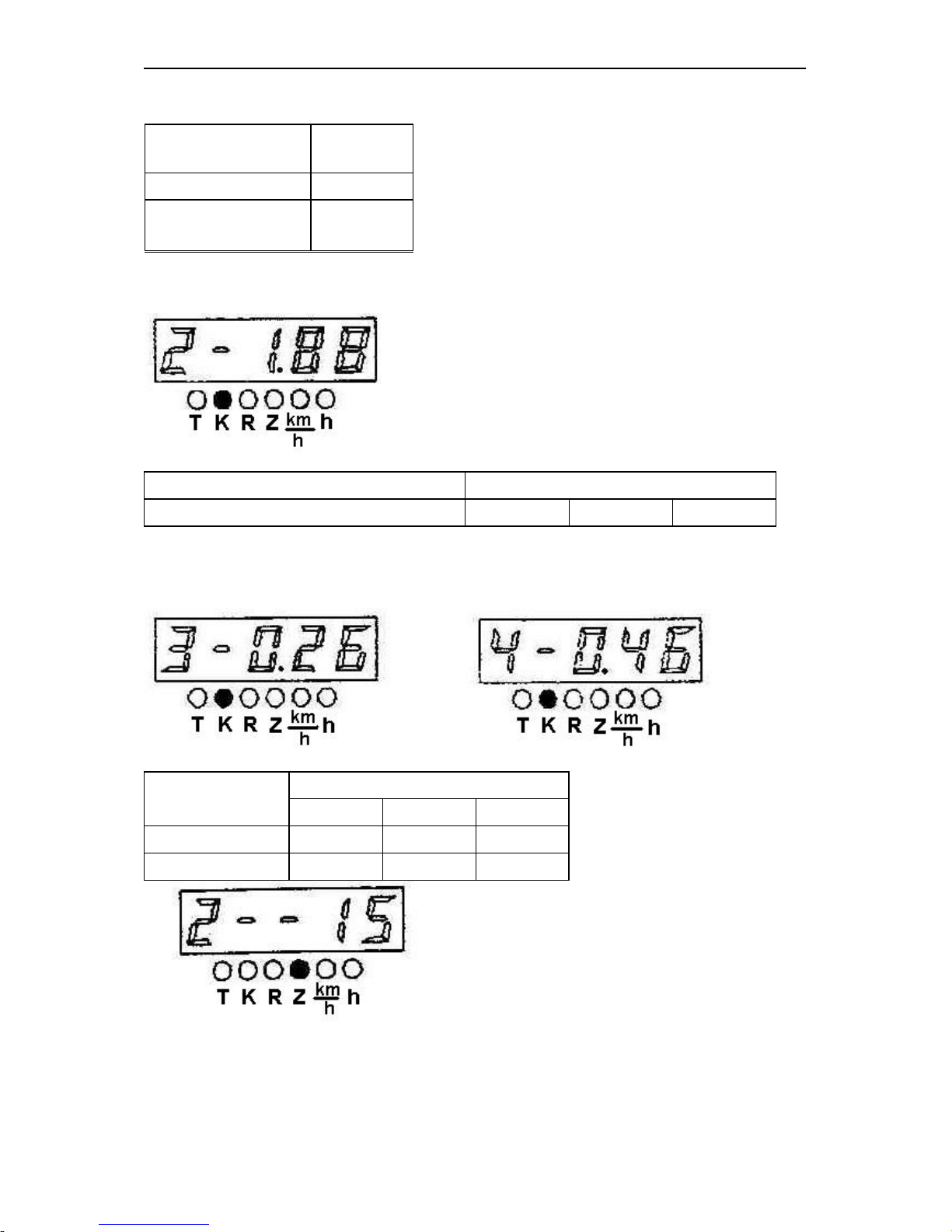
1. To display correctly the tractor motion speed, it is necessary to program the following parameters in the following order:
2. Gear ratio of the wheel reduction gear (parameter “K1”) from Table 5:
Table 5
Gear ratio of the wheel reduction
gear (K1)
Tractor model
3.43 Belarus-1221 and modifications
according to the number of gear teeth at the place of installation of the speed sensors
(parameter “Z1”) from Table 6:
Table 6
Number
of teeth
(Z1)
Tractor model
54 (56)* Belarus-1221 and modifications
* With driven gear 1522-2407122
rear wheel rolling radius (parameter “R”) from Table 7:
Page 32
BELARUS-1221.2/1221В.2/1221.3 Operating controls and instruments
31
Table 7
Tyre mark 18.4R38
Rk, m 0,829
Number coded 830
2. To display correctly the engine rotational speed, it is necessary to program the gear
ratio of the alternator drive (parameter “K2”) from Table 8 in the specified order:
Таблица 8
Gear ratio of the alternator drive (K2) Engine mark
2.41 Д-260.2 Д-260.2C Д-260.2S2
3. To display correctly the PTO’s rotational speed (540 and 1000), it is necessary to
program the gear ratio of the PTO 540 “K3” and PTO 1000 “K4” from Table 9 and the
number of teeth of the pinion at the place of installation of the PTO sensor “Z2”:
Тable 9
The gear ratio of
the PTO drive
Engine mark
Д-260.2 Д-260.2C Д-260.2S2
540 (К3) 0.26 0.26 0.26
1000 (К4) 0.46 0.46 0.46
- in case of absence of the PTO rotational speed sensor (signal from the phase winding
of the alternator serves as indication of the PTO rotational speed), the entered value of
the parameter “Z2” shall be equal to 0.
Page 33

BELARUS-1221.2/1221В.2/1221.3 Operating controls and instruments
32
1.8. Indicator Diagnostics and Troubleshooting
1. The diagnostics of the faults according to items 1-3 and 5 is similar to that of
the tachospeedometer;
2. Over- or understated readings of the engine rotational speed and PTO’s rota-
tional speed (with the normal movement of the pointer):
Check the correctness of programming the instrument according to the gear ratio of the
alternator drive (parameter “K2”): (see item 1.7);
3. Over- or understated readings of the tractor speed:
1. Check the correctness of programming the instrument according to the rolling radius
of the rear wheels (R) (see item 1.7);
2. Check the correctness of programming according to the number of teeth of the half-
axle pinion (Z1) (see item 1.7);
3. Check the correctness of programming of the gear rate of the wheel reduction gear
(K1) (see item 1.7).
4. No readings of the tractor motion speed:
Check the presence of the signals from the both speed sensors (BV1, BV2).
5. Signalling of operation of the speed sensor as in case of absence of a signal
from one of them:
a) in case of absence of the signal from the right wheel speed sensor (BV1) within 12 s
after starting the motion the symbol “□” is displayed on the right of the digital indicator;
check the connection and serviceability of the right wheel speed sensor;
b) in case of absence of the signal from the left wheel speed sensor (BV2) within 12 s
after starting the motion the symbol “□” is displayed on the left of the digital indicator;
check the connection and serviceability of the left wheel speed sensor.
1.9 Combined indicator АР80.3813 and combined indicating unit КД8105
(mounted on the tractors with the instrument dashboard 826-3805010)
The combined indicator (hereinafter referred to as the CI) and the control board (hereinafter referred to as the CB) monitor the operational parameters of the systems and units
of the Belarus tractors and provide the operator with the information on malfunction or
failure of a particular system.
The CI includes the indicators and alarm lamps monitoring the following parameters:
Page 34
BELARUS-1221.2/1221В.2/1221.3 Operating controls and instruments
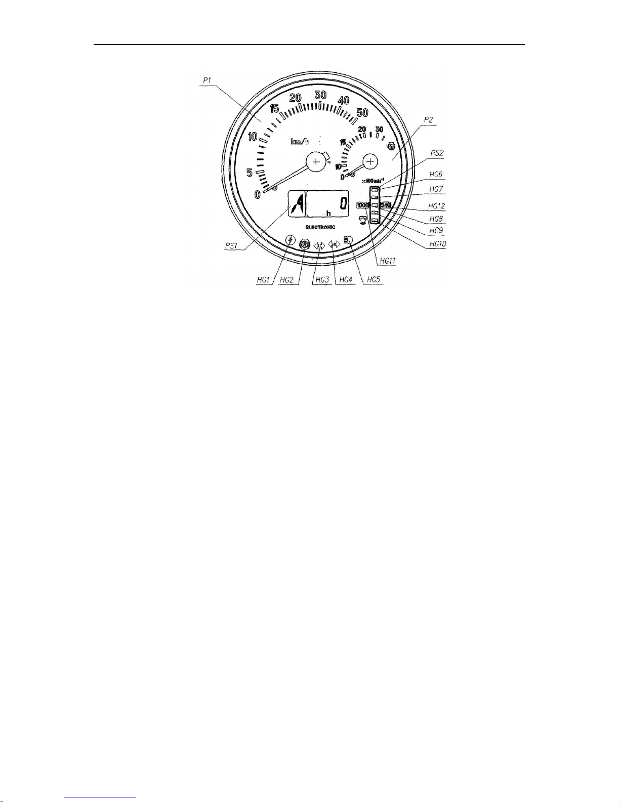
33
Р1 – speed indicator (pointer-type);
Р2 – engine rotational speed indicator (pointer-type);
РS1 – LCD, multifunction indicator (precise description and principle of РS1 operation
see below)
РS2 – PTO rotational speed indicator (light indicator);
HG1 – pilot lamp-alarm of the overvoltage in the on-board power supply system (red);
HG2 – pilot lamp-alarm of the parking brake application (red);
HG3 – pilot lamp-indicator of switching on the turn indicators of the tractor (green);
HG4 – pilot lamp-indicator of switching on the turn indicators of the trailer (green);
HG5 – pilot lamp-indicator of switching on the upper beam of the headlights (blue);
HG6, HG10 – PTO scale segments (yellow);
HG7… HG9 – PTO scale segments (green);
HG11, HG12 – scale range indicator of the PTO 1000 and 540, respectively (yellow);
Operating principle of the PTO rotational speed indicator:
1. In the absence of the PTO rotational speed sensor, the designations of the
“540” and “1000” scales as well as the indicator of the scale ranges HG11, HG12 light
up simultaneously on starting the engine (when a signal comes from the phase winding
of the alternator).
The indication of the PTO scale segments (with the account of the selected value
of the coefficient “KV2”) occurs on reaching the calculated PTO rotational speed equal
to 750 (rpm).
For reference: the indication of the PTO scale segments occurs on reaching the
engine rotational speed of 1400-1500 (rpm) and more.
Here, depending on the selected PTO speed mode (540 or 1000), the lit PTO
scale segments designate the rotational speed values according to Table 10.
Page 35
BELARUS-1221.2/1221В.2/1221.3 Operating controls and instruments
34
Table 10
Values of operation of the
“1000” scale segments
(rpm)
Segment location on the
scale
Values of operation of the
“540” scale segments
(rpm)
1150
HG6
650
1050
580
950
HG8
500
850
420
750*
HG10
320
2. In the presence of the PTO rotational speed sensor installed over the pinion of the
PTO shank, the combined indicator selects automatically the range (320-750 or 750-
1250) depending on the rotational speed of the shank that is accompanied visually by
switching on the backlight of the digital designation of the scale – “540” (HG11) or
«1000» (HG12), here the threshold values of operation of the scale segments change in
accordance with the requirements of Table 10.
The five LED 5 scale segments (HG6 … HG10) of the PTO light up starting from the
bottom one including the segment with the current value of the PTO rotational speed
included in the range of the lit state of that segment.
Notes:
- (*) is the rotational speed value, at which the “1000” scale designation is switched on;
- the “540” scale designation is only switched on in the presence of the signal from the
sensor and switched off when the “1000” designation is switched on or in case of signal
absence for more than 3 s.
- the exact value of the PTO rotational speed can be seen on the indicator РS1.
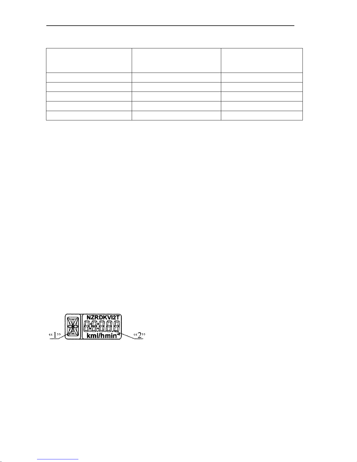
РS1, the LCD multifunction indicator displays simultaneously:
1. Digital designation of the position of the gearbox
control level (digits from 0 to 6) or lettering of the
reduction gear switch (letters L, M, H, N);
2. Current numerical value of one of the parameters
of the tractor systems.
The combined indicator receives the information on
the position of the gearbox control lever from the transmission control unit (if the complex electronic control system (CECS) is available) or from the control unit of the range
reduction gear (if provided). This parameter is displayed on the information field “1”. If
the control units are absent or not connected or in case of wire breakage, the letter “A”
is displayed in the information field “1”.
The information field “2” displays the following parameters:
LCD information fields
Page 36
BELARUS-1221.2/1221В.2/1221.3 Operating controls and instruments
35
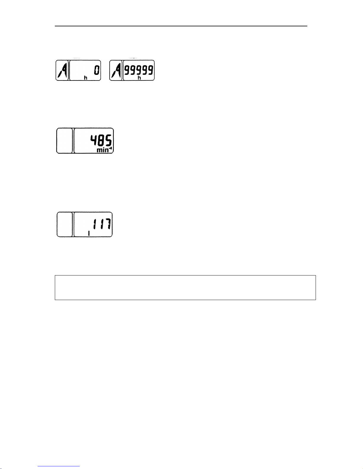
1. Total astronomic time of running the engine in hours.
The counter accumulates the information on the total engine running time and saves it
on switching off the power supply.
The reading range is from 0 to 99999 hours of the engine running.
2. PTO rotational speed:
In this mode, the PTO rotational speed is displayed in the digital form depending on the
signal from the PTO rotational speed sensor.
The mode is active if the tractor is equipped with the PTO rotational speed sensor.
3. Volume of the fuel remaining (if the frequency fuel volume sensor FFVS is provided):
In this mode, the current volume of fuel in the tank (in litres) is displayed.
Attention! This mode is only available on the stopped tractor in the absence of signals
from the speed sensors.
NOTE. To switch over between the indication modes “Total astronomic time of running the engine”, “PTO rotational speed”, “Volume of the fuel remaining” and fault
messages, press the “Mode” (Режим) button of the control panel.
HG1 is the indicator of the overvoltage in the on-board power supply system:
It lights up when the voltage of the on-board power supply system of the tractor exceeds
19 V and goes out when the power supply voltage level drops down to 17 V;
In this case the CI is fully de-energized and restores its serviceability when the voltage
drops down to the rated value.
HG2 is the indicator of the parking brake application:
The “Parking brake” indicator starts blinking on operation of the parking brake switch;
HG3, HG4 is the indicator of switching on the turn indicators of the tractor and trailer:
It blinks when the right or the left turn indicator is switched on by the steering-wheel-
mounted multifunction switch.
Page 37
BELARUS-1221.2/1221В.2/1221.3 Operating controls and instruments
36
HG5 is the indicator of switching on the upper beam of the road headlights; it lights up
when the upper beam of the road headlights is ON.
Note! The indicators light up and go out synchronously with the changes in the states of
the system sensors.
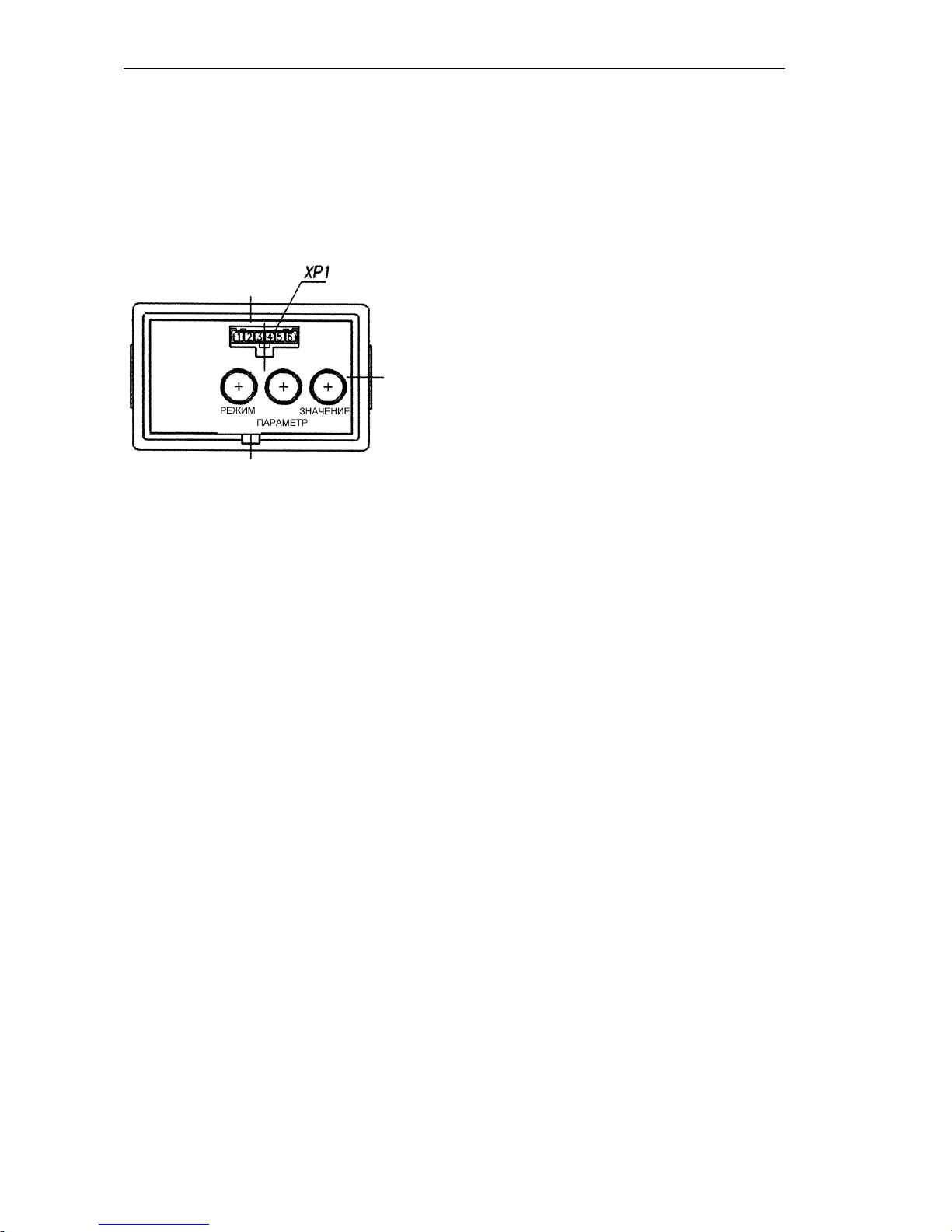
Indicator control board
РЕЖИМ – MODE
ЗНАЧЕНИЕ – VALUE
ПАРАМЕТР - PARAMETER
The programming board makes it possible to perform the manual programming of
the combined indicator by means of the “Parameter” (Параметр) and “Value” (Значе-
ние) buttons and to modify the mode of display of the parameters to be shown on the
LCD.
The diagnostic connector ХР1 located on the front panel of the control board makes
it possible to perform the automatic programming (reprogramming) of the CI by means
of a special instrument (if provided). Should such an instrument be unavailable, the programming shall be performed by means of the above buttons.
1.10 CI programming procedure
1. On selecting the fixed value of the programming parameter:
1.1. On pressing the “Parameter” (Параметр) button for the first time, the LCD is
switched to the mode of viewing the parameter to be programmed and its numerical
value. On pressing this button repeatedly, the parameters are switched over cyclically.
1.2. On pressing successively the “Parameter” button, the numerical value of the set parameter to be programmed changes.
1.3. The mode is exited automatically if neither “Parameter” (Параметр) nor “Value”
(Значение) button has been pressed within 7.0 sec.
On exiting the mode, the last values of the parameters selected by the “Value”
(Значение) button are saved.
2. When entering the unfixed value of the programming parameter:
2.1. Select the parameter, the values of which shall be set, by means of the “Parameter”
(Параметр) button;
2.2. Press twice the “Mode” (Режим) button; the least digit of the numerical value starts
blinking;
Page 38
BELARUS-1221.2/1221В.2/1221.3 Operating controls and instruments
37
2.3. To change the value of the blinking digit of the parameter, use the “Value”
(Значение) button;
2.4. To go to the more significant digit, press the “Parameter” (Параметр) button;
2.5. To exit the mode of programming an unfixed value of any parameter, press twice
the “Mode” (Режим) button;
2.6. On exiting the above mode, the digits of the entered value of the parameter become lit steadily;
2.7. The newly entered value is set the last in the list of the parameter values allowed to
be programmed;
Entering the parameters to be programmed:
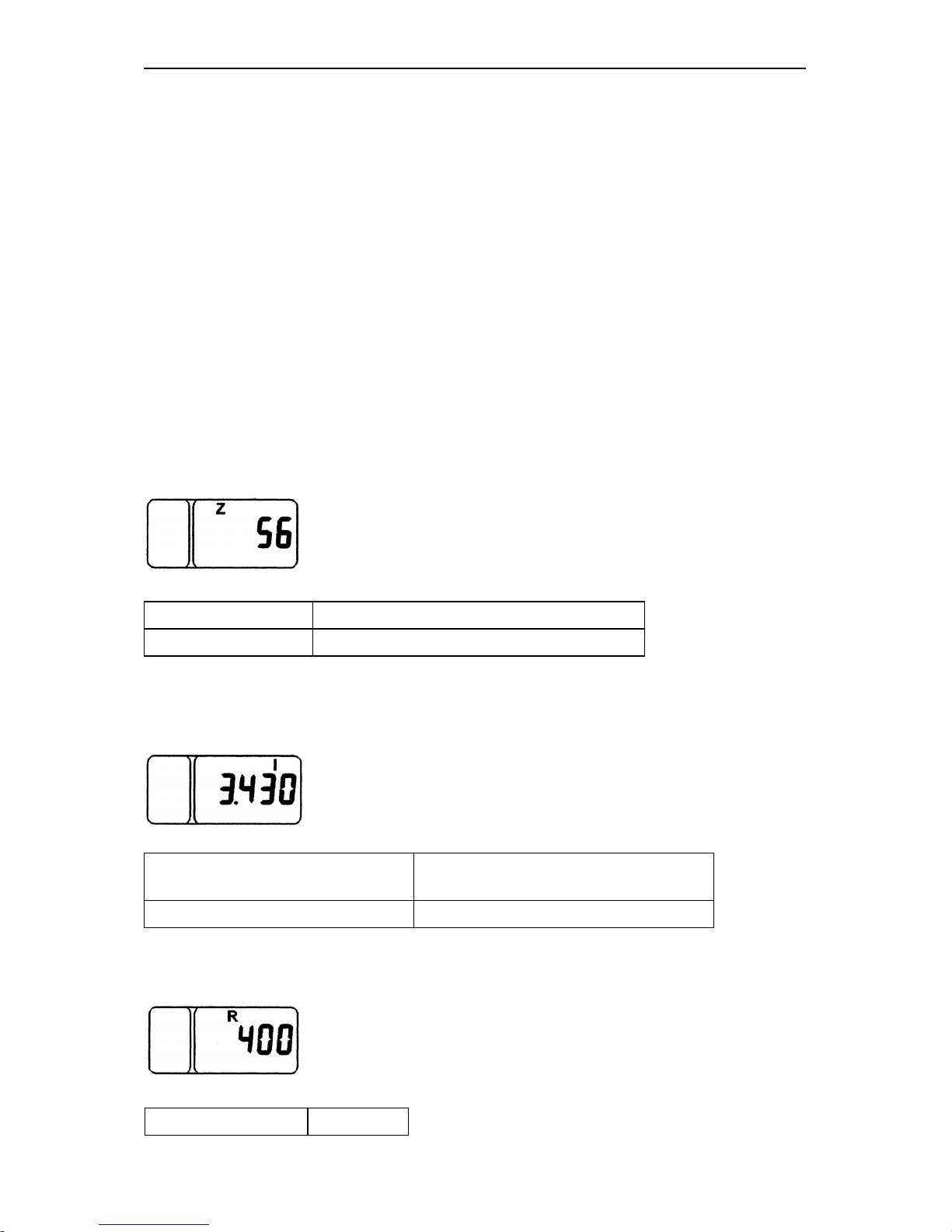
1. To display correctly the tractor motion speed, it is necessary to program in the specified order the following parameters:
Parameter “Z” is the number of pinions teeth of the final shafts of the driving wheels
(right and left), over which the (rotational) speed sensors are installed;
Select from the Table:
Number of teeth (Z) Tractor model
54 (56)* Belarus-1221 and modifications
* With driven gear 1522-2407122
Parameter “I” is the multiplying factor of the gear rate of the wheel reduction gear;
Select from the Table
Gear ratio of the wheel reduc
tion
gear (I)
Tractor model
3,43 Belarus-1221 and modifications
Parameter «R»
R is the rear wheel rolling radius (mm);
Select from the Table
Tyre mark 18,4R38
Page 39
BELARUS-1221.2/1221В.2/1221.3 Operating controls and instruments
38
Rk, m 0,829
Number coded 830
2. To display correctly the engine rotational speed, it is necessary to program in the
specified order the gear ratio of the alternator drive (parameter “K”) from Table 8-6:
Select from the Table
Gear ratio of the alternator drive
(К2)
Engine mark
2.41 Д-260.2 Д-260.2С Д-260.2S2
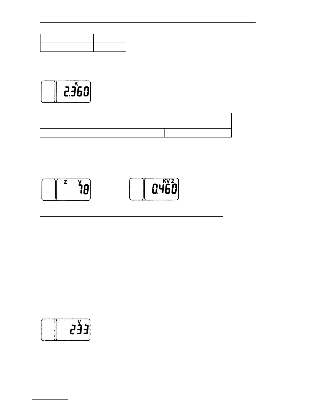
3. To display correctly the PTO’s rotational speeds (540 and 1000), it is necessary to
program in the specified order the gear ratio PTO “КV2” and the number of teeth of the
pinion at the place of installation of the PTO sensor “ZV”:
Select from the Table
Gear ratio of the PTO drive
Tractor model
Belarus-1221 and modifications
(КV2) 0.46
- in the absence of the PTO rotational speed sensor (the signal from the phase winding
of the alternator serves as a signal for indication of the PTO rotational speed) the value
of the parameter “ZV” to be entered shall be equal to 0.
- in the absence of the PTO rotational speed sensor (the signal from the phase winding
of the alternator serves as a signal for indication of the PTO rotational speed) the value
of the parameter “ZV” to be entered shall be equal to 0.
4. To display correctly the residue of fuel in the tank (if the FFRS sensor is installed), it
is necessary to program the fuel tank volume “V” in the specified order:
For tractors with plastic fuel tank, set the value of 140 litres.
Also, when pressing the “Parameter” (Параметр) button in the programming mode,
the list of programmable parameters displays the independent parameter of the ad-
Page 40
BELARUS-1221.2/1221В.2/1221.3 Operating controls and instruments
39
justed content of the counter of the astronomic time of running the engine. This parameter is unavailable for measurement; it presents the precise (to 1/10 hours) value of the
number of hours of the engine running.
On switching on the backlight of the instrument scales (the main light switch (MLS)
is set to the positions II “The backlight of the instrument dash and clearance lights are
ON” and III “The consumers of the position II and front road headlights and clearance
lights are ON”), the brightness of the PTO indicator segments and LCD is automatically
reduced.
IMPORTANT! Each time the power supply of the CI is switched ON, the functioning
of the pointer indicators and PTO indicator scale elements is tested. Within one second after this, the indicator pointers deviate from the initial marks above the following
first marks of the scales (above “5” for the motion speed and above “10” for the rotational speed), and all the segments and designations “540” and “1000” of the PTO
scale are switched on.
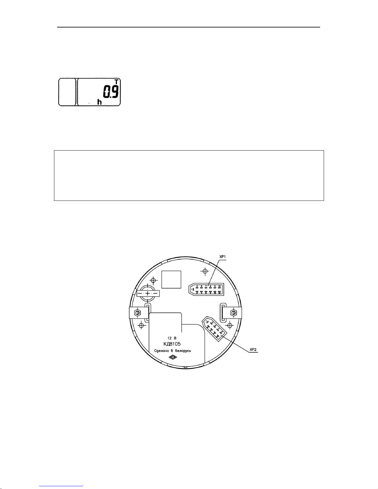
1.11 Connecting the tachospeedometer
To connect the tachospeedometer to the instrumentation system, a 13-contact block
(ХР1) and a 9-contact block (ХР2) are provided on the rear panel of the instrument (Fig.
5).
Fig. 5
The identification of the outputs of the blocks is given in Tables (11) and (12).
Page 41

BELARUS-1221.2/1221В.2/1221.3 Operating controls and instruments
40
Table 11
Contact
Address of the XP1 connector output
1
To the terminal “–“ (common)
2
To the power supply unit “+12 V”
3
To the PTO rotational speed sensor
4
To the rotational speed sensor “Left wheel”
5
To the transmission control unit
6
To the rotational speed sensor “Right wheel”
7 8
To the phase winding of the alternator
9
To the switch of the backlight
10
To the switch of the headlight upper beam
11
To the switch of the trailer turn indicators
12
To the switch of the parking brake
13
To the switch of the tractor turn indicators
Table 12
Contact
Address of the XP2 connector output
1
To the terminal “–“ (common)
2
To the control board contact “Indication mode”
3
To the control board contact “Parameter selection”
4
To the control board contact “Parameter value”
5 6 7
To the fuel volume sensor
8
To the control board contact “M”
9
To the control board contact “+UBZ”
1.12. Indicator Diagnostics and Troubleshooting
1. No instrument backlight:
Check the power supply of the output “9” of the 13-contact block (ХР1) of the instrument
(Fig. 5);
2. Jerking and jumps of the pointer of the engine rotational speed indicator over
the dial: poor contact on the alternator terminal and, therefore, poor signal from the
phase winding of the alternator. Repair.
3. Jerking of the pointer and understating the reading of the engine rotational
speed:
- Check and adjust the tension of the alternator driving belt.
4. Over- or understated readings of the engine and PTO’s rotational speeds (with
the normal movement of the pointer):
- Check the correctness of programming the instrument according to the gear ratio of
the alternator drive (parameter “K”): (see item 1.10);
Page 42
BELARUS-1221.2/1221В.2/1221.3 Operating controls and instruments
41
5. The counter of astronomical hours of the engine running fails to accumulate
the operating time:
- Check the connection of the wire to the contact «8» of the instrument block (ХР1) and
the presence of the frequency signal from the phase winding of the alternator.
6. Over- or understated readings of the tractor speed:
1. Check the correctness of the instrument programming according to the rolling radius
of the rear wheels (R) (see item 1.10);
2. Check the correctness of the programming according to the number of teeth of the
half-axle pinion (Z) (see item 1.10).
3. Check the correctness of programming the multiplying factor of the gear rate of the
wheel reduction gear (I) (see item 1.10).
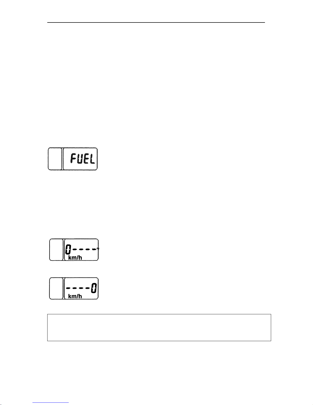
7. The “FUEL” reading appears on the indicator display
Check the connection and serviceability of the frequency fuel volume sensor (FFVS) to
the contact “7” of the block (ХР2).
8. No readings of the tractor motion speed:
- Check the presence of the signals from the both speed sensors (BV1, BV2).
9. The “0km/h----” or “----0кm/h” readings appear on the indicator display within
10-12 s after starting the motion of the tractor:
- no signal from the left speed sensor (BV2) check the serviceability of the sensor.
- no signal from the right speed sensor (BV1) check the serviceability of the sensor.
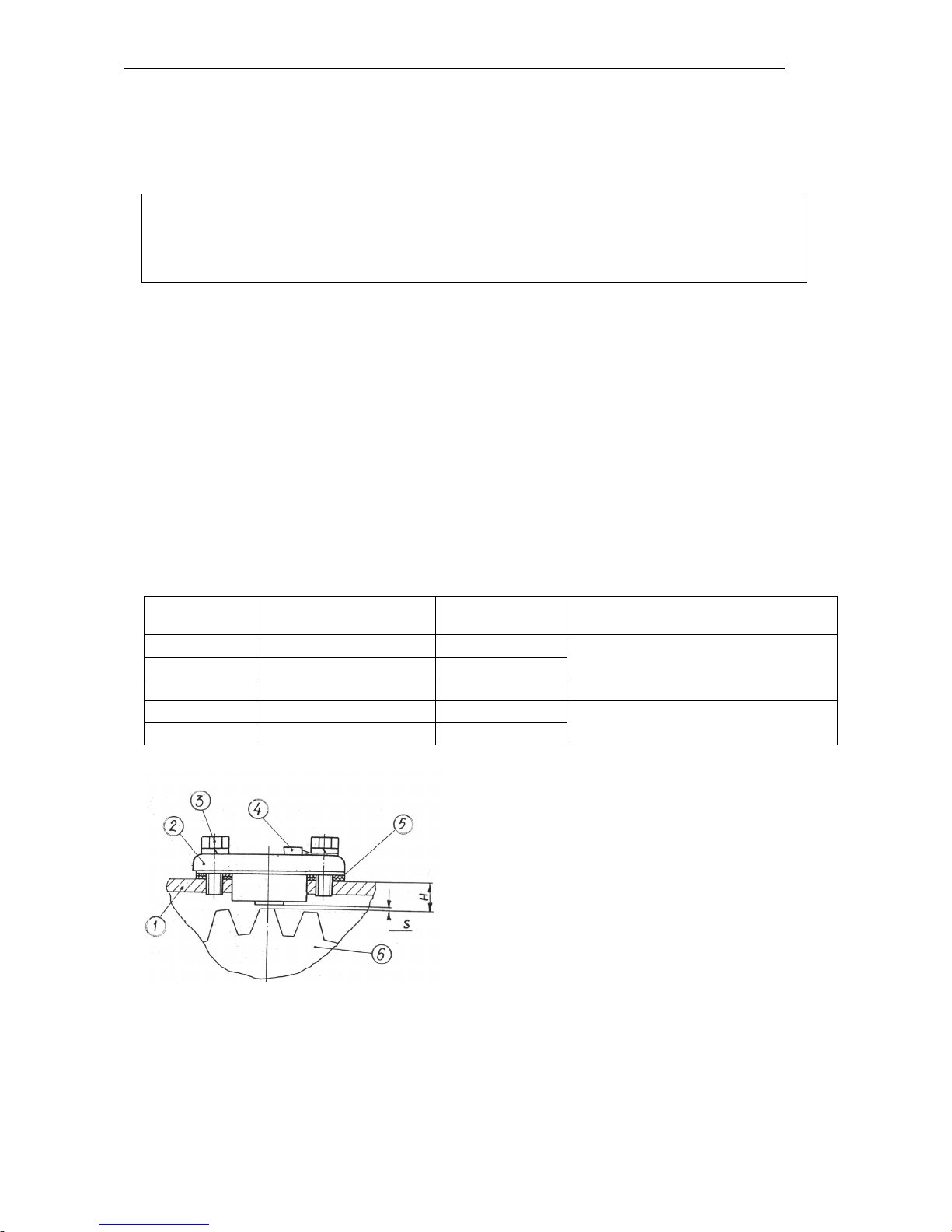
ATTENTION! The speed readings are affected considerably by the speed sensor setting and adjustment performed when replacing or repairing the speed sensor. The
gap “S”
between the end face of the sensor (2), Fig. …, and projection of the tooth of
the final pinion (6) of the rear axle shall be as specified in Table … below
Every message about faults (Example: 0----, FUEL) is shown according to the
priority on the LCD regardless the information displayed. On pressing successively
the “Mode” (Режим) button, the messages shall be paged. When viewing the last
message and pressing repeatedly the “Mode” button, the LED is switched to the
Page 43
BELARUS-1221.2/1221В.2/1221.3 Operating controls and instruments
42
mode of displaying operating parameters specified below over the cycle. The faults
are displayed on the LCD each time the instrument is switched on until the fault is
eliminated.
Note:
- On switching on the power supply of the CI, the LED shows the information in the
indication mode selected until the power supply of the CI is switched off in case of
absence of the messages about faults.
1.13 Setting and Adjustment of the speed sensors (BV1, BV2) (Fig. 6)
The speed sensors (2) are fastened by means of the bolts (3) to the cover of the rear
axle housing (1) in the zone of the left and right final pinions (6) of the final drives.
The gap “S” between the end face of the sensor and projection of the tooth of the final pinion shall be adjusted by means of the spacers (5) as follows:
1. measure the dimension “Н” from the surface of the cover (1) to the tooth
projection;
2. select and place the necessary number of spacers for setting the gap “S”
corresponding to the measured value “Н” (see Table 13);
3. install the ground wire (4) and tighten the bolts (3).
Table 13
Н, mm
Number of spacers
(Pos. 5)
S, mm Note
11,25-12
4
1,05-1,6
When using the cover (1) with the
thickness S=6 mm
12,1-13
3
0,8-1,8
13,1-13,73
2
0,9-1,53
13,25-14
2
1,05-1,8
When using the cover (1) with the
thickness S=8 mm
14,1-15,73
1
0,9-2,53
Fig. 6. Setting the speed sensors:
1 – cover of the rear axle cover;
2 – speed sensor (BV1, BV2);
3 – bolt;
4 – ground wire;
Page 44
BELARUS-1221.2/1221В.2/1221.3 Operating controls and instruments
43
5 – adjusting spacers;
6 – final pinion.
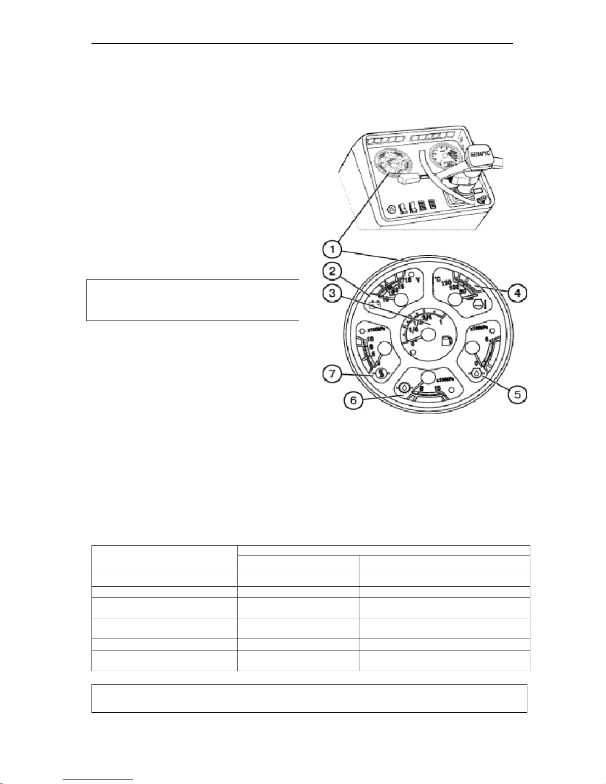
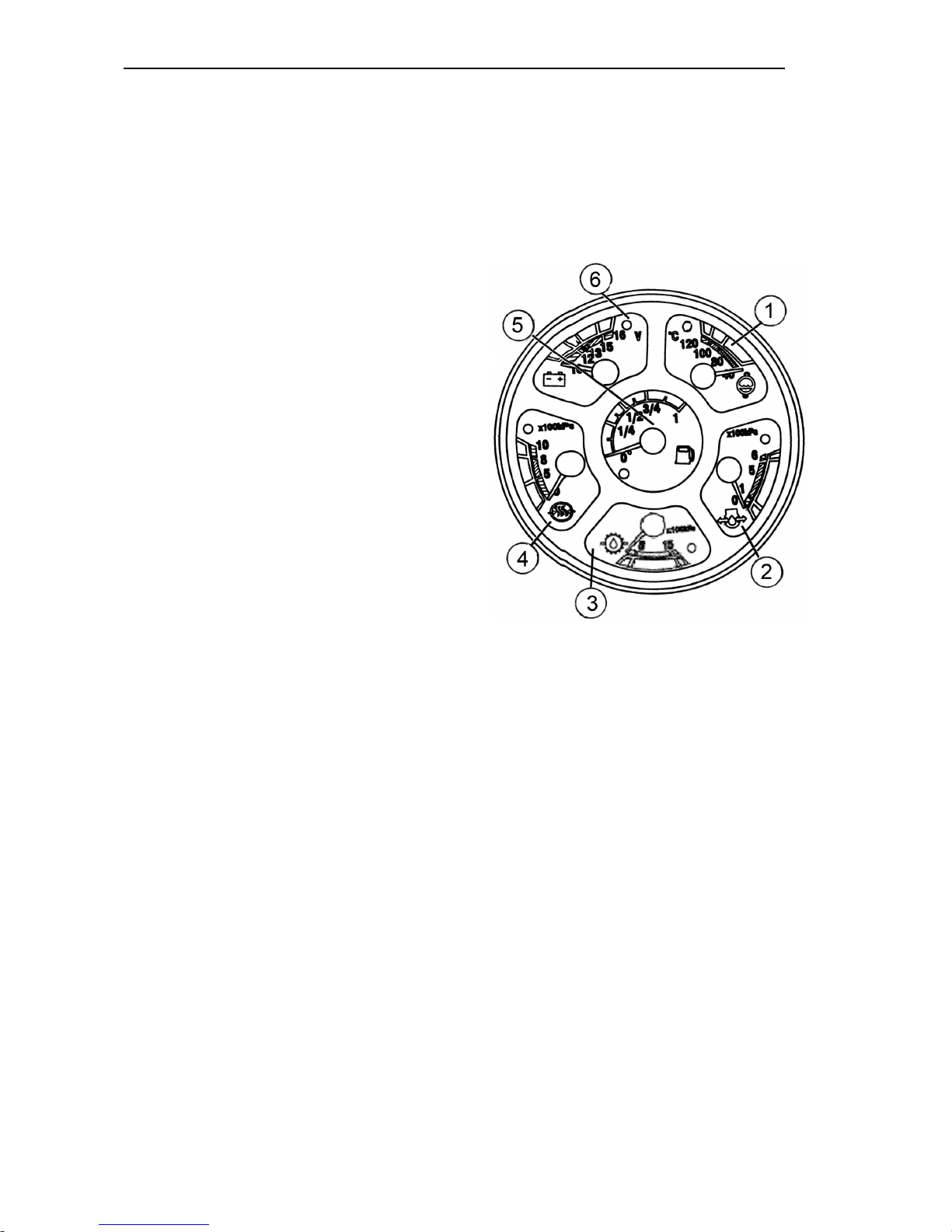
1.14 Combination meter (fig. 7)
Engine cooling fluid temperature indicator (4)
(with the emergency temperature control
lamp) The indicator scale has three
zones:
• operating – 80 - 100°C – green;
• engine warm-up zone – 40 - 60°C -
yellow
• non-operating (overheating) –
100 - 120°C – red.
Attention! When the emergency temperature control lamp flashes on stop the
engine, find and repair the fault.
Voltage indicator (2)
(with the control lamp of additional accumulator battery charging)
It displays the accumulator battery voltage, when the engine is not running and
the starter switch key (3) (page. Г3) is in
the “I” position. When the engine is running, it indicates the voltage at the generator terminals. The voltage indicator
scale has the following zones:
Fig. 7. Combination meter
Scale zone, colour
Power supply system state
when the engine is running
when the engine is
not running
13,2 – 15,2 В – green
normal charging mode
10,0 – 12,0 В – red
generator is not working
Accumulator battery is run down
12,0 – 13,2 В – yellow
No charging of accumulator
battery (low charging voltage)
Accumulator battery has normal charging
15,2 – 16,0 В – red
Accumulator battery overcharging
12,7 – 12,0 – yellow
Start of battery discharge
white hairline in yellow zone
The rated emf of the accumulator battery
is12.7 V
IMPORTANT! When the engine is running and voltage meter pointer is in the green
zone the indicator should not burn.
Page 45

BELARUS-1221.2/1221В.2/1221.3 Operating controls and instruments
44
Engine oil pressure indicator (5) (with emergency pressure drop control lamp)
The indicator scale has three zones:
— operating — 1,0 – 5,0 kgf/cm2;
— non-operating — 0,0 – 1,0 и 5,0 – 6,0 kgf/сm2.
IMPORTANT! See after the emergency pressure drop control lamp. If the lamp burns
during the engine running, stop the engine immediately, find and repair the fault.
Indicator of the air pressure in the pneumatic system (7) (with the emergency pres-
sure control lamp)
The indicator scale has three zones:
— operating — 5,0 – 8,0 kgf/сm2;
— non-operating — 0,0 – 5,0 and 8,0 – 10,0 kgf/сm2.
Gear oil pressure indicator (6) (without emergency lamp)
The indicator shows gear oil pressure and oil pressure in hydraulically operated FDA
drive clutch.
The indicator scale has three zones:
— operating — 8,0 – 15,0 kgf/сm2;
— non-operating — 4,0 – 8,0 and
15,0 – 18,0 kgf/сm
2
.
Normal indicated values — 9…12 kgf/сm
2
.
Indicator of the fuel level in the tank (3) (with emergency lamp of reserve level)
The instrument has four sectors:
0 – 1/4 – 1/2 – 3/4 – 1.
Never allow the fuel tank to run dry.
Page 46
BELARUS-1221.2/1221В.2/1221.3 Operating controls and instruments
45
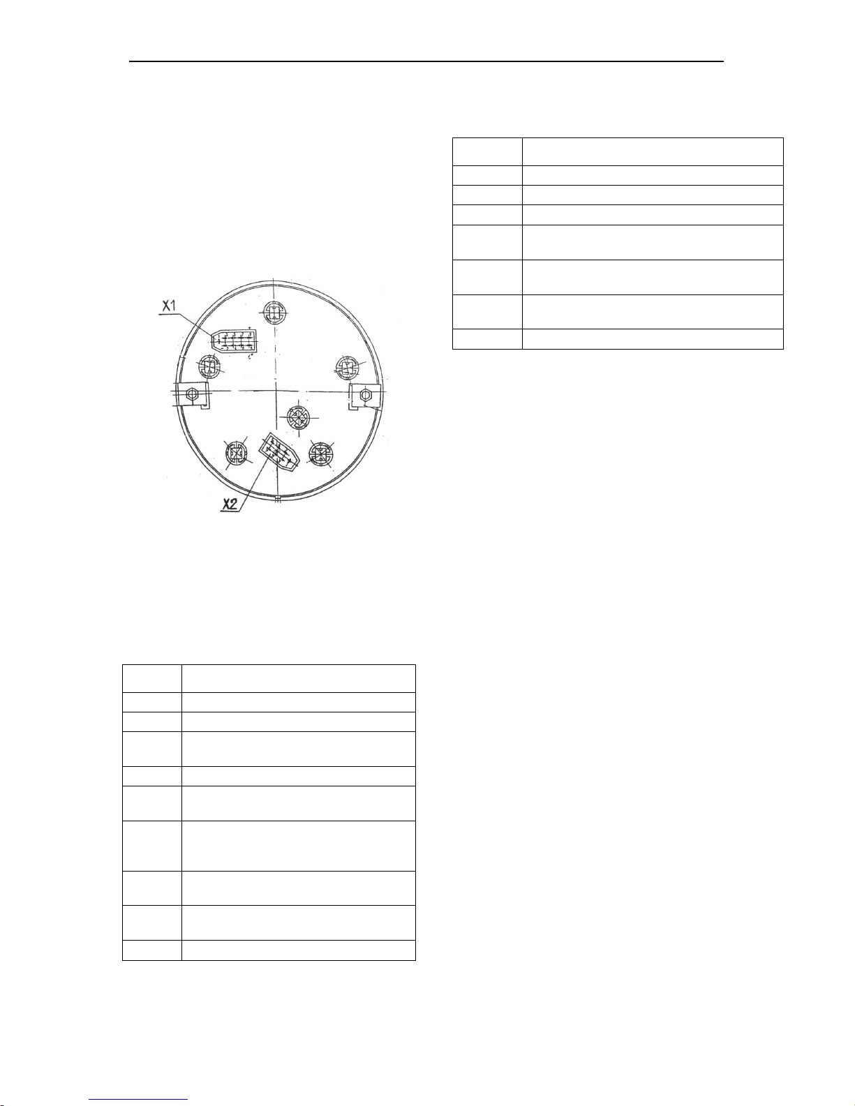
1.15 Connection of the combina-
tion meter
To integrate the combination meter to
the instrumentation system, the rear
panel is provided with two blocks Х1 and
Х2 (Fig. 8).
The purpose of the contacts of the
blocks of the combination meter is
shown in Tables 15, 16.
Fig. 8. Blocks for connecting the combination
meter (rear view):
Х1 – 9-contact block;
Х2 – 7-contact block.
Block «Х1»
Table 15
Contact Address
1
To the instrument backlight switch
2
To the “–” terminal of the battery
3
Monitoring the storage battery charg-
ing
4
Buzzer
5
To the sensor of the oil pressure in
the engine (ВР1)
6
To the sensor of the emergency tem-
perature of the engine cooling fluid
(SК1)
7
To the sensor of the emergency oil
pressure in the engine (SP2)
8
To the sensor of the cooling fluid
temperature (BK1)
9
To the “+” SB terminal (12 V)
Block «Х2»
Table 16
Contact Address
1
Reserved
2
Reserved
3
To the fuel level sensor (BN1)
4
To the gearbox oil pressure sensor (not
used)
5
To the sensor of emergency drop of the
air pressure (SP4)
6
To the sensor of the reserve fuel level
(BN1)
7
To the sensor of the air pressure (ВР2)
Page 47
BELARUS-1221.2/1221В.2/1221.3 Operating controls and instruments
46
1.16 Combination meter diagnostics
and troubleshooting
1. No backlight of the instrument
scales on setting the SA10 central
light switch:
1. Check the presence of the power
supply voltage at the terminal “1” of the
block “Х1” (to the instrument backlight
switch) and at the terminal “9” (to the
power supply unit “+ 12 V”).
In case of absence of the voltage, eliminate the open circuit. If the voltage is
present:
2. Check the state of the backlight lamps
and replace them, if necessary.
2. The temperature indicator (1), Fig.
9, operates jointly with the thermistor-type temperature sensor BK1
(ДУТЖ-02М, resistance range:
243…22.5 Ω).
2.1. The temperature indicator pointer
goes off-scale:
1. Breakage of the wire to the terminal
“9” of the block “Х1” (“+” 12 V of the SB);
2. Breakage of the wire to the terminal
“2” of the block “Х1” (“–” of the power
supply);
3. If there is no breakage, the temperature indicator is faulty.
2.2. The pointer of the temperature
indicator is set before the initial point
of the scale:
1. Breakage of the wire to the terminal
“9” of the block “Х1” (“+” 12 V of the SB);
2. Breakage of the wire to the terminal
“8” of the block “Х1” (to the temperature
indicator BK1);
3. Fault of the temperature sensor;
4. Fault of the temperature indicator.
3. Indicators of the:
oil pressure in the engine (2), air
pressure in the pneumatic system (4),
oil pressure in the gearbox (3) operate with rheostat-type sensors
(0…184 Ω), respectively ДД-6М (ВР1),
ДД-10-01М (ВР2) и ДД-20М (ВР3).
IMPORTANT! To avoid inaccuracy in
the temperature indication, use the
ДУТЖ – 02М temperature sensors mentioned above.
Рис. 9 Instrument board
3.1. The indicator pointer is set before the initial point of the scale:
1. Breakage of the wire to the terminal
“2” of the block “Х1” (“–” of the power
supply);
2. Breakage of the wire to the terminal
“9” of the block “Х1” (“+” of the power
supply);
3. If there is no breakage, the pressure
indicator is faulty
3.2. The indicator pointer goes offscale:
1. Breakage of the wires to the terminal
“5” of the block “X1”, to the terminals “4”,
“7” of the block «Х2» or short circuit inside the indicator;
2. The pressure indicator is faulty.
4. Fuel level indicator (5).
It operates with the rheostat sensor
(BN1) of the type (ДУМП-21М (320…0
Ω)) installed in the fuel tank
Page 48

BELARUS-1221.2/1221В.2/1221.3 Operating controls and instruments
47
NOTE! If there is no fuel in the tank
when switching on the indicator; the indicator pointer shall be at the initial point
of the scale. If the indicator is switched
off or there is a wire breakage, the indi-
cator pointer shall go off-scale.
4.1. The indicator pointer is before
the initial point of the scale:
1. Breakage of the wire to the terminal
“9” of the block “Х1” (to the terminal
“+12V”);
2. Breakage of the wire to the terminal
“3” of the block “Х2” (to the fuel level
sensor);
3. The fuel level sensor is faulty;
if there is no breakage and the sensor is
in good repair, replace the combination
meter or repair the fuel level indicator.
4.2. The indicator pointer goes offscale:
1. Breakage of the wire to the terminal
«2» of the block “Х1” (output “–“ of the
power supply);
2. If there is no breakage, the fuel level
indicator is faulty. Repair the indicator or
replace the combination meter.
Page 49
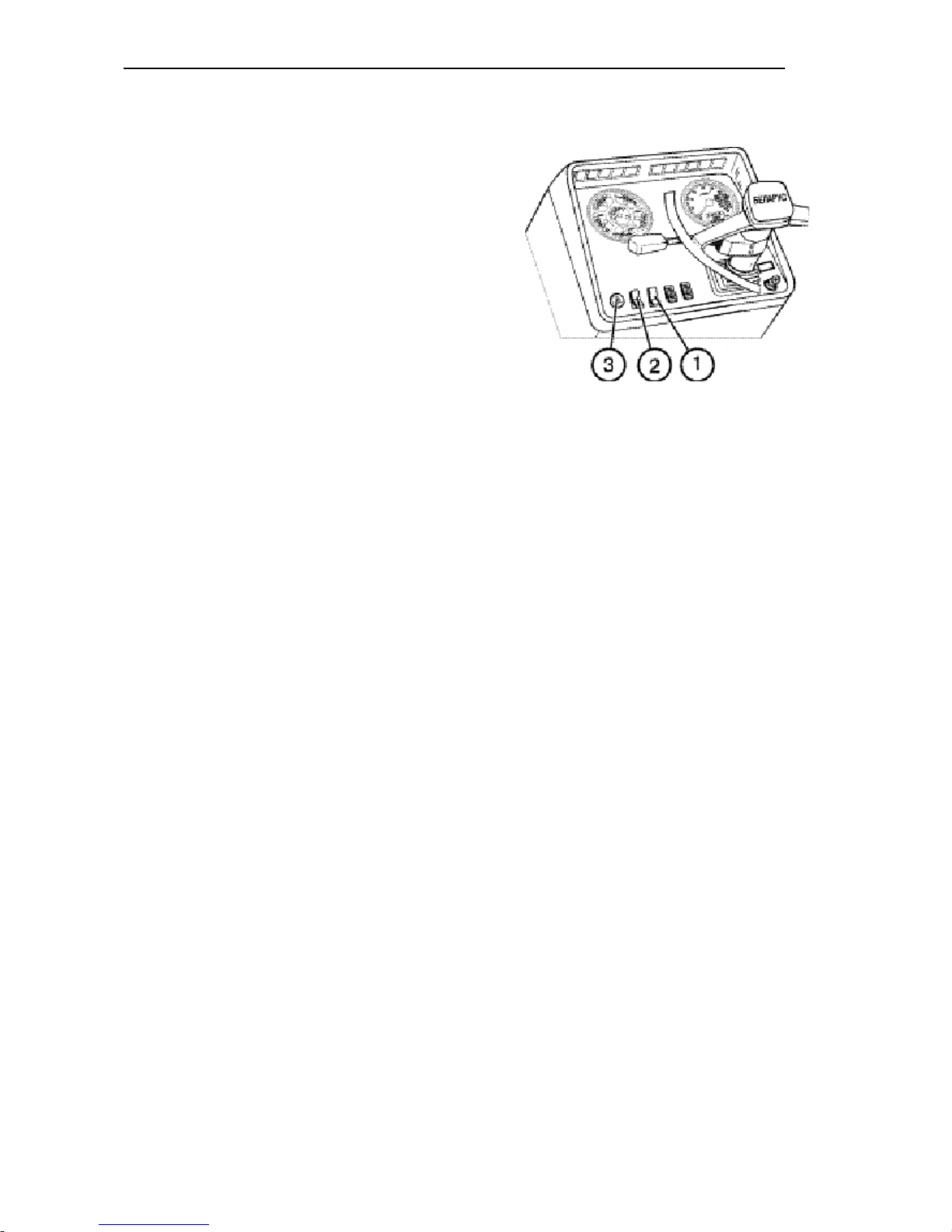
BELARUS-1221.2/1221В.2/1221.3 Operating controls and instruments
48
Front windscreen washer switch (1)
Pressing the button (1) windscreen
washer the switches on.
Three-position light switch (2)
The button (2) has three positions:
1 — “OFF”;
2 — “Dashboard lighting, clearance
lights and number plate light ON”;
3 — “All control lamps units including
the front headlights ON”.
Fault signalling switch (3)
Pressing the button (3) switches the
fault signalling on. There is a control
lamp inside the button, which blinks simultaneously with the flashing light signalling.
Page 50
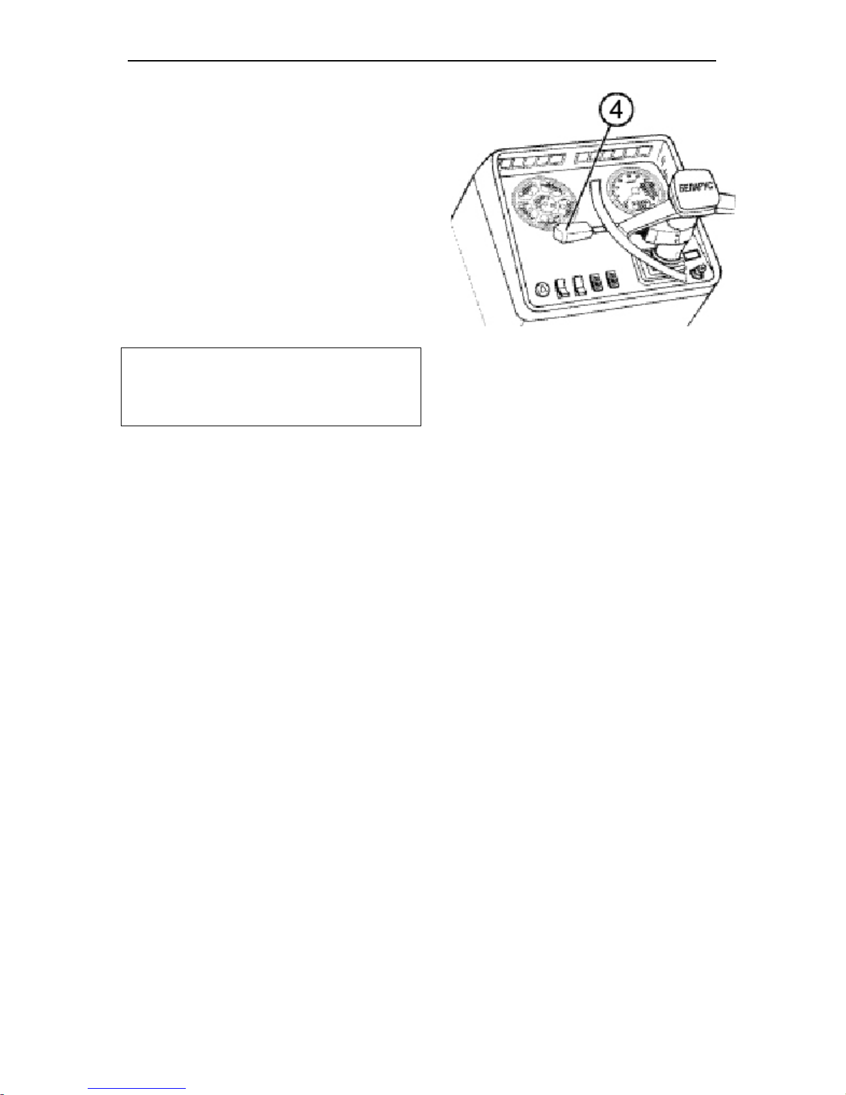
BELARUS-1221.2/1221В.2/1221.3 Operating controls and instruments
49
Steering-Wheel-Mounted (Multifunction)
switch (4)
It ensures the switching-on of the turn
indicators, toggling the beam of the road
headlights (lower/upper beam), upper
beam warning and horn beep.
Turn indicator
Turning the lever (4) of the steering-
wheel-mounted switch forward or back-
wards switches on the right or left turning
indicator, respectively.
NOTE: After completing the turn of the tractor, the lever automatically returns
to the
neutral position.
Horn beep
Pressing the switch lever end the beep
switches on.
Upper/lower beam
When the road headlights are switched on
pushing the lever switches on the “upper
beam” and pulling the same lever switches
on the “lower beam”.
Pulling the lever further from the “lower
beam” position up to the stop switches on
the upper beam (non-fixed position). Releasing the lever puts it back in the “lower
beam” position.
Page 51
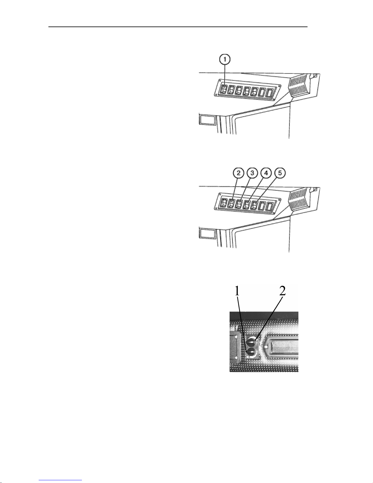
BELARUS-1221.2/1221В.2/1221.3 Operating controls and instruments
50
Front windscreen wiper switch (1)
Pressing the button (1) switches on front
windscreen wiper.
Cab heater and fan switch (2)
Pressing the button (2) switches on the
cab air ventilation.
The switch has 3 positions:
1 — “OFF”(the upper part of the button
is sunk to the maximum);
2 — “Low air supply mode ON”;
3 — “High air supply mode ON”.
Rear working lights switch (3)
Pressing the button (3) switches the rear
working lights and the roof backlight
lamp.
Front working lights switch (4)
Pressing the button (4) switches on the
front working lights and the button backlight lamp.
“Road-train” sign lighting switch (5)
On pressing the button (5), the three orange lights on the roof forepart are
switched on and the button is backlit.
Conditioner control
On the conditioner control unit there
are switches (1) и (2).
1 – Airflow adjustment switch;
2 – Conditioner switch off and re-
frigerating capacity adjustment.
Page 52
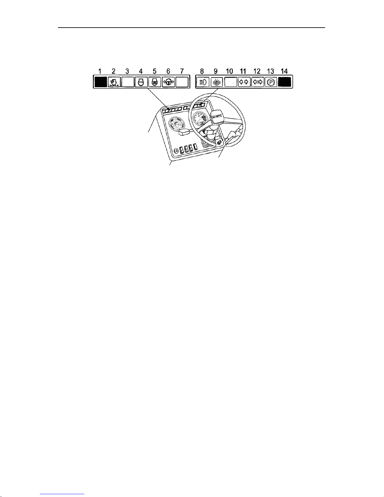
BELARUS-1221.2/1221В.2/1221.3 Operating controls and instruments
51
Check indicators of the dashboard (Dashboard 80-3805010-Д1)
1 and 14 – Buttons for testing the serviceability of the control lamps unit. On
pressing the button, all the lamps shall
be lit.
2 – Air filter blocking. The control lamp
(orange) lights up when the maximum
allowed level of filter blocking is exceeded and it needs cleaning.
3 – Reserved.
4 – Engine start lamp: This orange control lamp lights up on turning the starter
switch key to position II to indicate that
the starting system functions properly. If
the lamp blinks at the frequency of 1.5
Hz, the gearbox control lever is not in
neutral position or the engine starting
locking switch circuit is out of order. If
the lamp blinks at the frequency of 3.0
Hz, there is a failure in the alternator
phase winding circuit. Eliminate the
fault and restart.
5 – Starting aid lamp (orange).
6 – HPS emergency oil pressure. The
lamp (red) lights up when oil pressure in
HPS feeding system is below the allowable level.
7 – Reserved.
8 – Upper beam indicator: Blue control
lamp lights up when switching on the
upper beam of the front headlights.
9 – Rear axle differential locking control
lamp. The lamp (green) is on when
switching automatic differential locking
(ADL).
10 – Reserved.
11 – Tractor turn indicator (green).
12 – Trailer turn indicator (green).
13 – Parking brake indicator (red).
Page 53
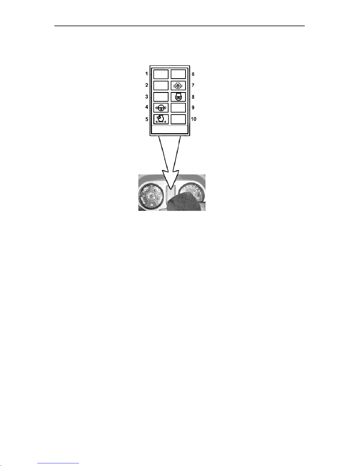
BELARUS-1221.2/1221В.2/1221.3 Operating controls and instruments
52
Control lamps of the dashboard (dashboard 826-3805010)
1 – Reserved indicator (green)
2 – Reserved indicator (green)
3 – Reserved indicator (red)
4 – HPS emergency oil pressure. The
lamp (red) lights up when oil pressure in
HPS feeding system is below the allowable level.
5 – Air filter blocking (orange). The
control lamp lights up when the
maximum allowed level of filter blocking is exceeded and it needs cleaning.
6 – Reserved indicator (blue).
7 – Rear axle differential locking control
lamp (green). The lamp (green) is on
when switching automatic differential
locking.
8 – Starting aid lamp (orange)
9 – Reserved indicator (red).
10 – Reserved indicator (red).
Page 54
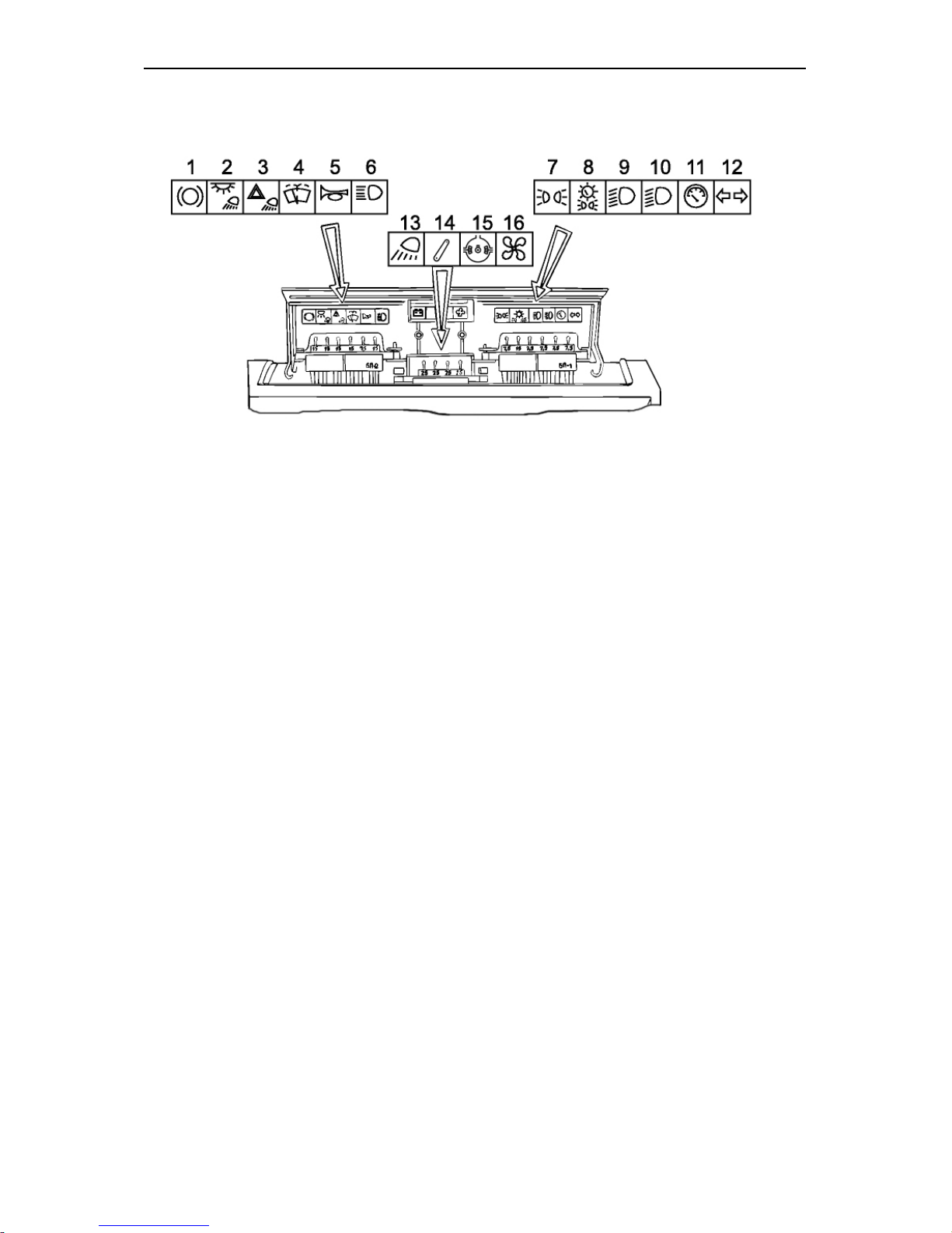
BELARUS-1221.2/1221В.2/1221.3 Operating controls and instruments
53
Fuses
Three electric circuit fuse boxes are
installed in the dashboard. To get access to the fuses, remove the screw
on the dashboard cover and open it.
The fuses protect the following electric
circuits of the tractor against overloads:
1 — Braking signal (15 A);
2 — Cab light and rear working lights
(15 A);
3 — Fault signalling (15 A);
4 — Windscreen wiper and washer
(15 A);
5 — Horn (7.5 A);
6 — Upper beam of the road headlights (15 A);
7 — Left clearance lights (7.5 A);
8 — Right clearance lights and backlights of the dashboard and registration
plate (15 A);
9 – Lower beam of the left road headlight (7.5 A);
10 – Lower beam of the right road
headlight (7.5 A);
11 – Instrumentation, control lamps
blocks, parking brake indicator (7.5 A);
12— Turn indicator relay (7.5 A);
13— Front working lights (25 A);
14— HMS supply (25 A);
15— Side board supply (PTO, DL) (15
A);
16— Heating system fan (25 A).
The storage battery charging circuit is
protected with the fuse rated at 60 A.
WARNING! To prevent the electric
wiring from burning, never apply
fuses of higher current rating than
specified above. If the fuse blows often, detect the reason and eliminate
it.
Page 55

BELARUS-1221.2/1221В.2/1221.3 Operating controls and instruments
54
In case of fuse blowing due to a short circuit, proceed as follows:
1. Connect the wires from the pilot lamp to the terminals of the fuse box at the place
of the fuse blown.
a) If there is a short circuit, the lamp will be lit with incandescence,
b) If the circuit and consumer are intact, the lamp will not be lit or will be lit dimly.
2. Check the circuit from the fuse to the consumer and ensure that the lamp is not
lit or is lit dimly (in the presence of a switched on consumer in the circuit);
3. Fit a new fuse.
During the operation, the contact resistance between the fuse and its holders can
increase due to oxidization.
It results in increase of the voltage drop in the circuit and heating causing the circuit
failure. The defect is detected by the disturbance of the operation of the consumer
(reduction of the power) and heating of the fuse. Eliminate the defect by cleaning the
holder and fuse from the oxide film.
Page 56
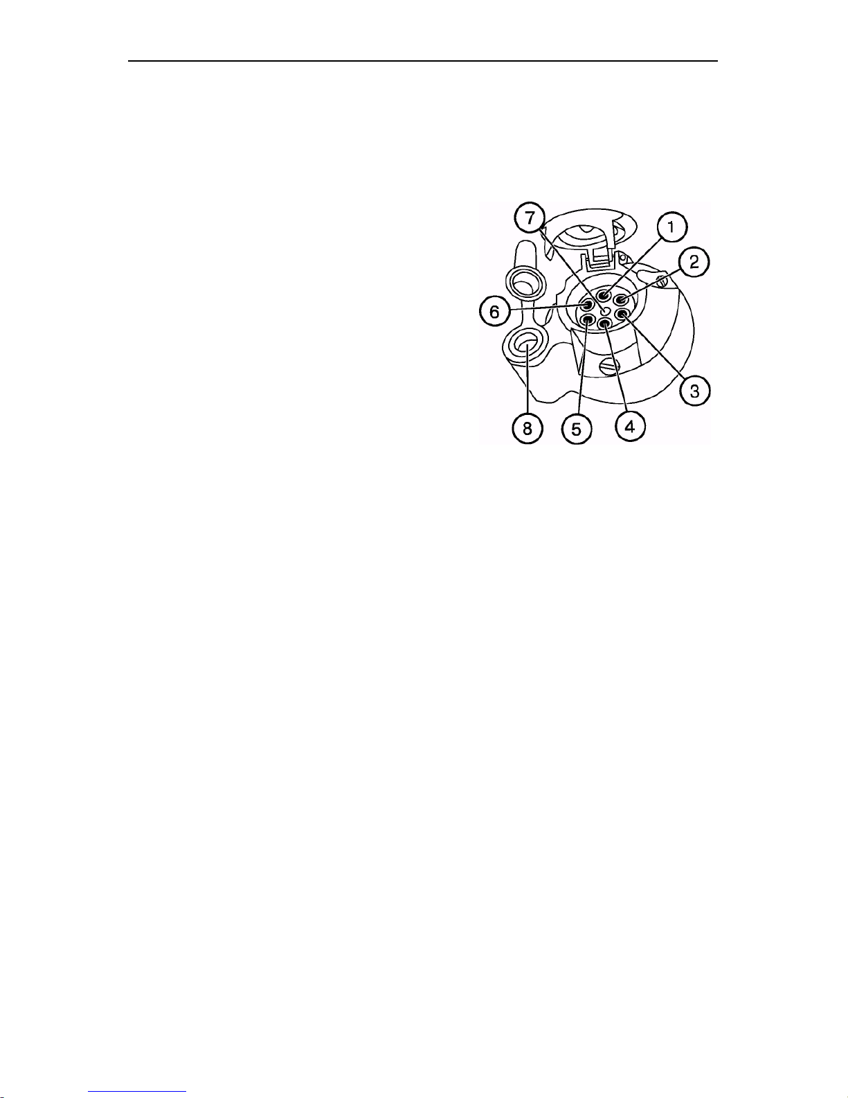
BELARUS-1221.2/1221В.2/1221.3 Operating controls and instruments
55
Electric equipment connector components
A combined multipin socket is designed
for connecting the trailer electrical
equipment or electrical equipment of
trailed agricultural implement and service lamp. It is installed on the cab’s
rear support. A plug of the wire bundle
of the hitched machines and a plug of
service lamp are connected to the
socket.
Socket connection terminal marking:
1 – Turn indicator, left;
2 – Horn;
3 – “Ground”;
4 – Turn indicator, right;
5 – Right clearance light;
6 – Stop light;
7 – Left clearance light;
8 – Service lamp connection.
Page 57
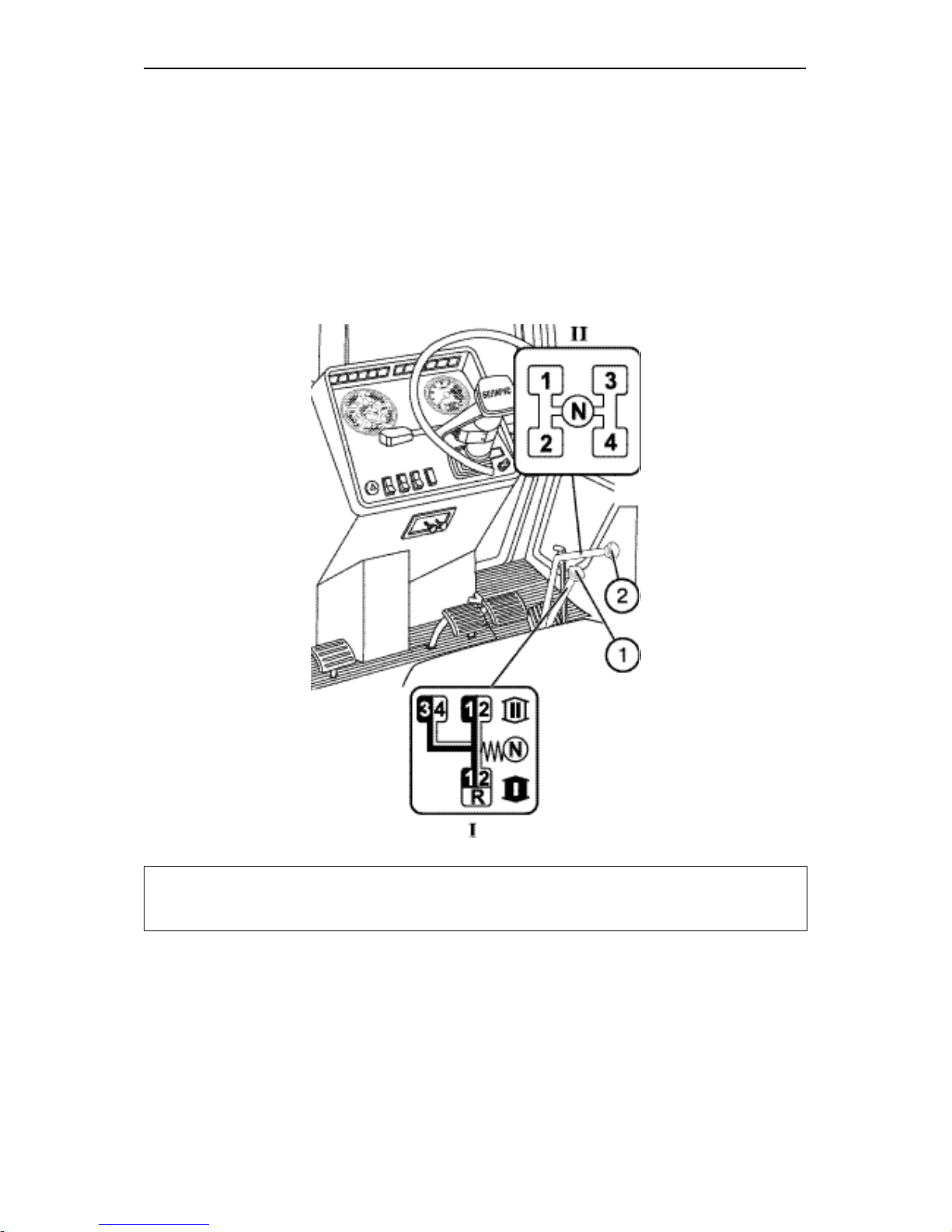
BELARUS-1221.2/1221В.2/1221.3 Operating controls and instruments
56
Gearbox control (16F+8R)
The gearbox is controlled by two levers:
a lever of ranges shifting (1) and a lever
of gears shifting (2).
Select the required ranges and gears in
accordance with the shifting patterns I
and II as shown on the figure below.
IMPORTANT! In order to shift the gear correctly smoothly, without jerks, move the
gear shifting lever (2) in accordance with the pattern (see the figure above) and keep it
pressed until the gear is switched.
Page 58
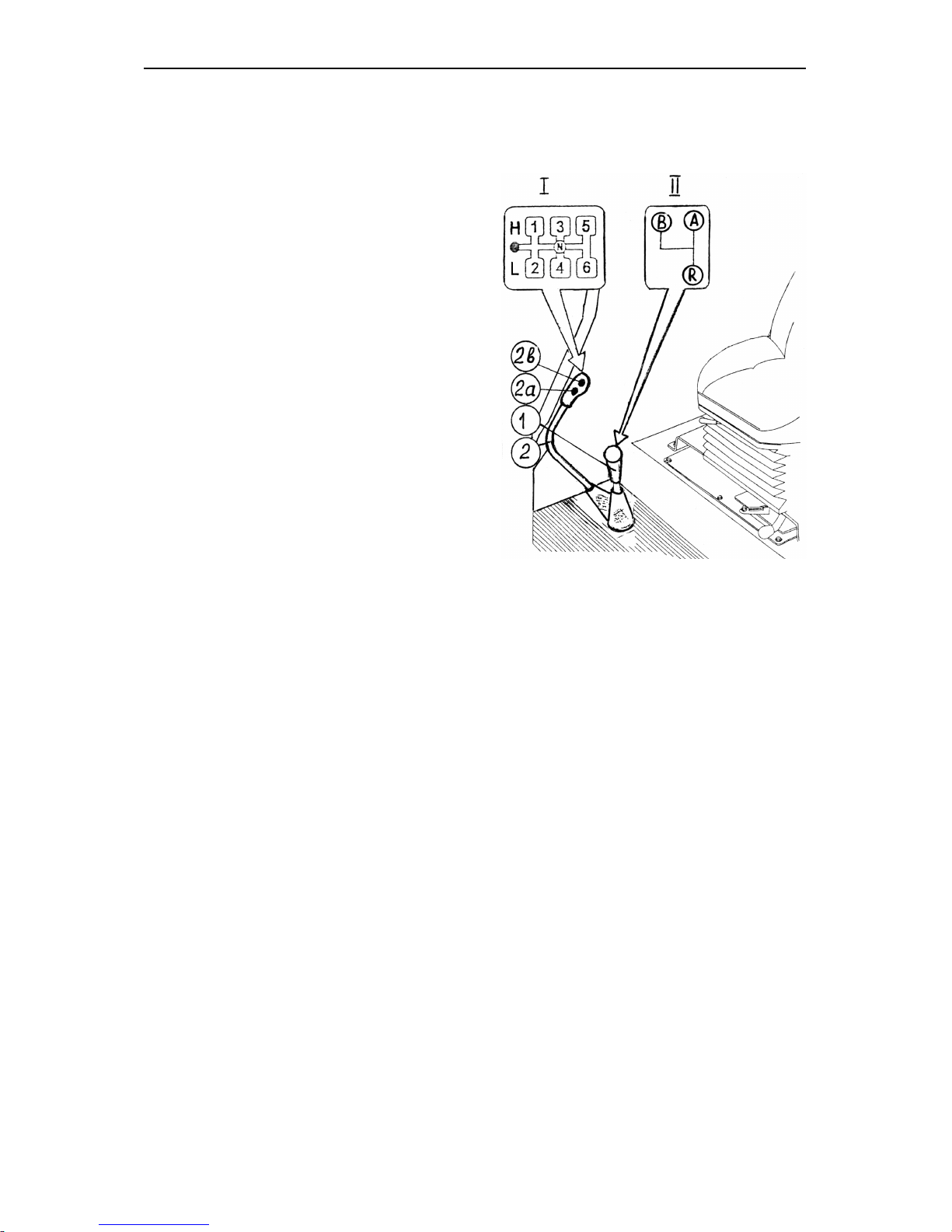
BELARUS-1221.2/1221В.2/1221.3 Operating controls and instruments
57
Gearbox control (24F+12R) (if installed)
Gears shifting lever (2)
The shifting pattern is shown in the figure on the right (pattern I).
“On” button (2а) of gearbox reducer
low gear (L).
On” button (2в) of gearbox reducer
high gear (H).
Ranges shifting lever (1)
The shifting pattern is shown in the figure on the right (pattern II).
А – two low ranges of forward motion;
В – two high ranges of forward motion;
R – two ranges of reverse motion;
Н –high pass of gearing;
L – low pass of gearing.
Page 59
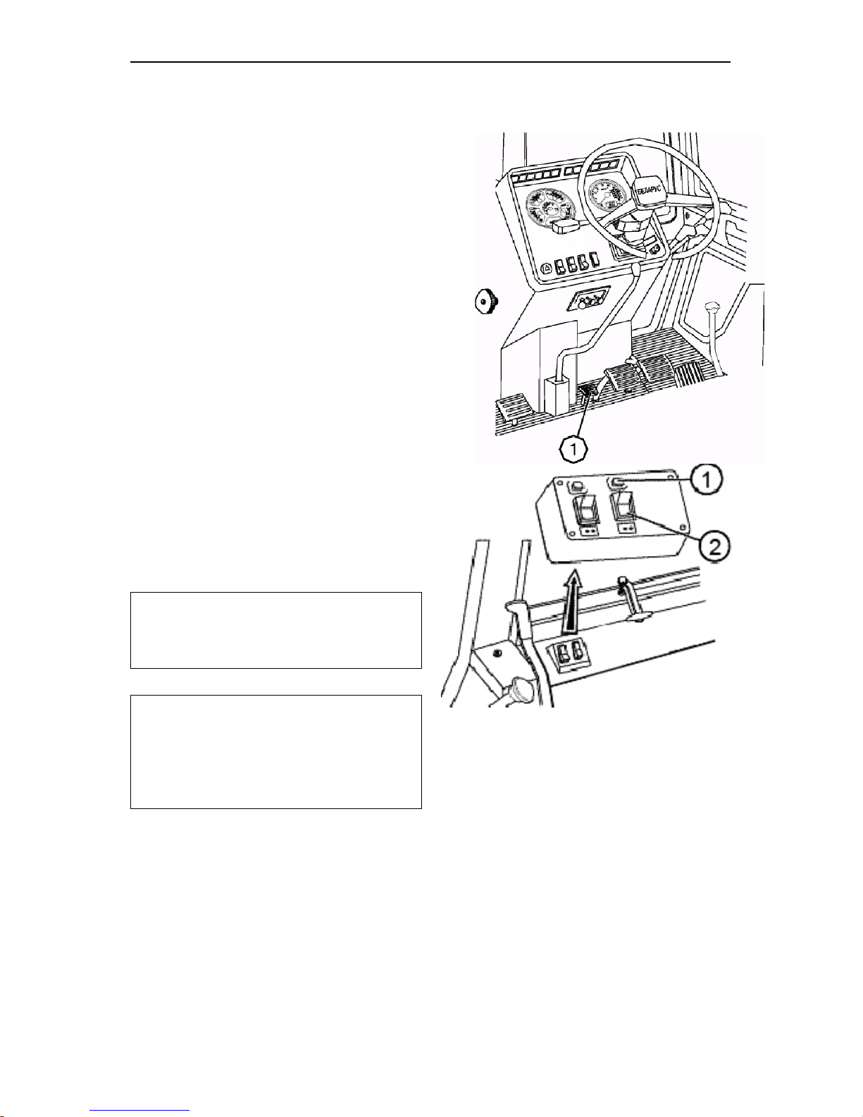
BELARUS-1221.2/1221В.2/1221.3 Operating controls and instruments
58
Control of the rear axle differential
lock
The rear axle differential lock is controlled by the button (4), located on the
dashboard near FDA control button (2).
Three position button (4) has the following positions:
• “Automatic locking” — on pressing the
upper part of the button (fixed position);
• “Differential lock is switched off —
middle position (fixed);
• “Forced blocking” — on pressing the
lower part of the button (unfixed). When
the button is released it automatically
switches to the middle position (“Differential lock is switched off”).
On switching on the differential lock
alarm lamp (3) lights up, which goes off
when the differential lock switches on automatically and when the button (4) is put
in the middle position.
Important! Engage the forced differential lock only shortly to overcome
road obstacles and carry out the field
and transportation works.
Warning: Do not use the differential
lock at the speeds exceeding 10 km/h
and when turning the tractor. Otherwise the tractor control becomes difficult, power transmission is quickly
worn out, the safety is endangered.
Electrical schematic of FDA and rear
axle differential lock control system is
given in the section “Appendix”.
Page 60
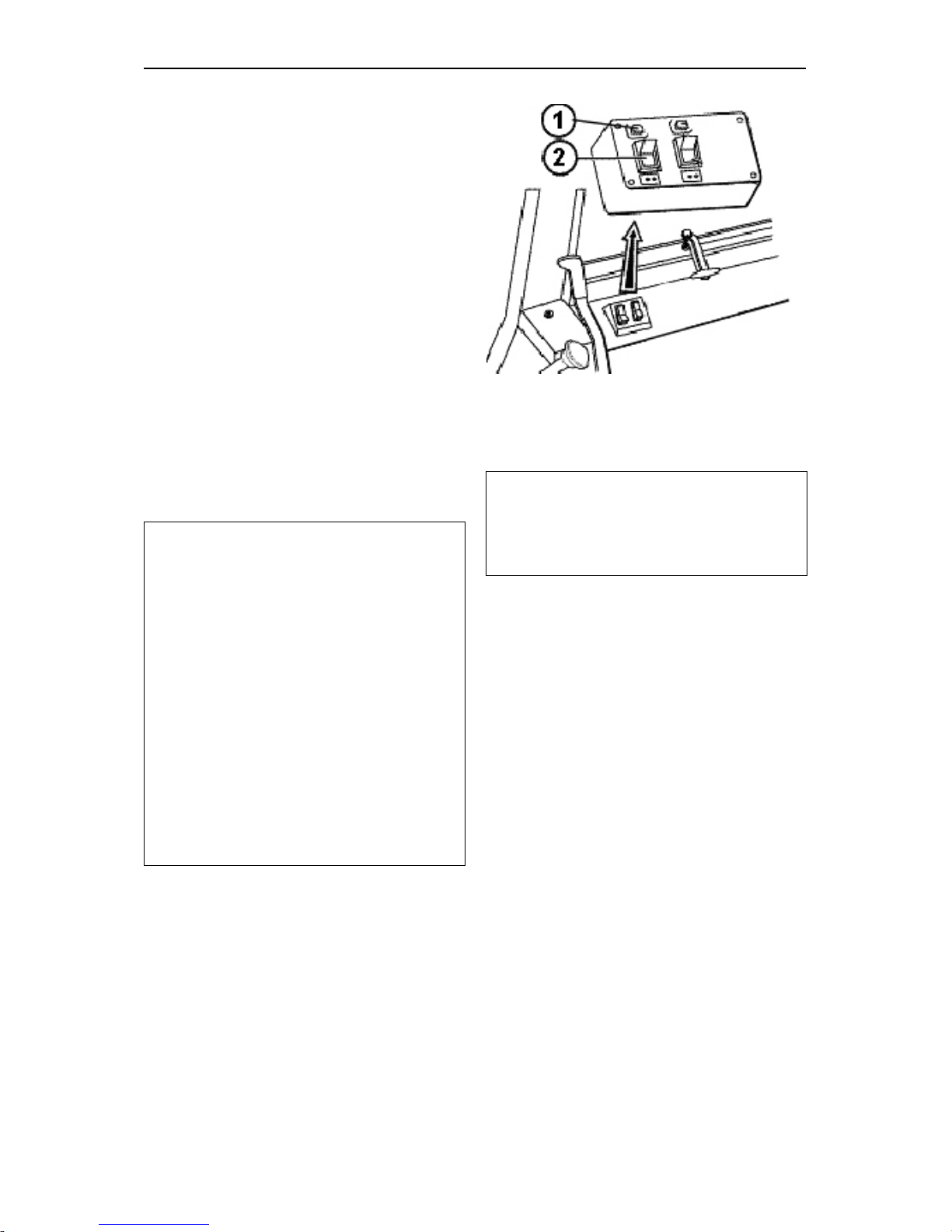
BELARUS-1221.2/1221В.2/1221.3 Operating controls and instruments
59
FDA drive control
FDA drive is controlled by the button (2),
located on the board above the right control unit. The button (2) has three fixed
positions:
• “FDA is automatically “on” — on
pressing the upper part of the button;
• “FDA is “off” — middle position of the
button;
• “Forced FDA engagement” — on
pressing the lower part of the button.
On engaging FDA drive the alarm lamp
(1) lights up. The lamp goes out on
putting the button (2) in the middle position and in the moment of switching off
the drive in the automatic mode.
Attention!
1. Operating on the roads with hard
surface switch off the FDA (middle position of the button (2) in order to prevent tyres and drive parts from increased wear.
2. Use the forced FDA engaging mode
shortly only to overcome obstacles and
when operating on reverse,
3. It is categorically forbidden to operate in the mode of forced FDA engagement when the speed is over 15
km/h.
4. It is categorically forbidden to use
FDA in the mode of automatic engagement by the reverse motion.
Electrical schematic of FDA and rear
axle differential lock control system is
given in the section “Appendix”.
Note: A braking relay is installed in the
electrical line of FDA drive control, it
ensures automatic switching on of FDA
when pressing synchronized pedals of
tractor brakes.
Page 61
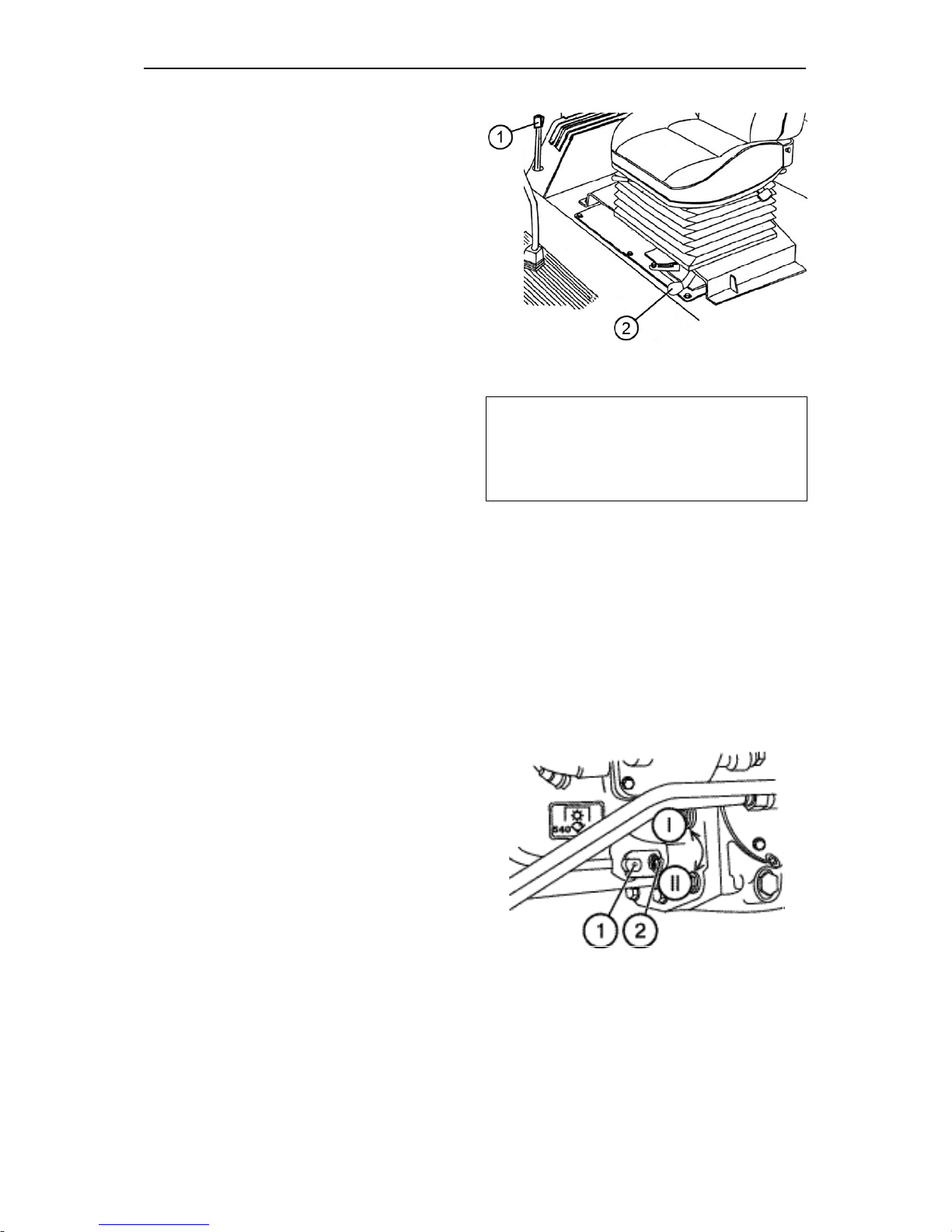
BELARUS-1221.2/1221В.2/1221.3 Operating controls and instruments
60
Switching on rear PTO shaft
The lever (1) has 2 positions:
• “PTO is engaged” — extreme upper
position,
• “PTO is disengaged” — extreme lower
position.
Independent and synchronous PTO
drives
The lever (2) has three positions:
• “Independent drive is engaged” — ex-
treme right position;
• “Synchronous drive is engaged — ex-
treme left position;
• “Disengaged” — middle position.
Engage the synchronous PTO drive only
at low gears on minimum engine idle
speed doing the following:
• Start the engine and set the minimum
idle speed;
• Press home the clutch pedal and en-
gage I or II gear;
• Release the clutch pedal slowly and
simultaneously turn the lever (2) in the
extreme left position.
Speed switch of independent PTO
drive
Independent drive lever (1) has two positions:
I — 540 rpm — extreme, contraclockwise;
II — 1000 rpm — extreme clockwise.
To set a required PTO speed release the
bolt (2), turn the lever (1) and tighten the
bolt (2).
Important! Use the PTO synchronous
drive only at low gears at tractor motion speed not higher than 8 km/h.
Otherwise tractor power train may get
seriously damaged.
Page 62
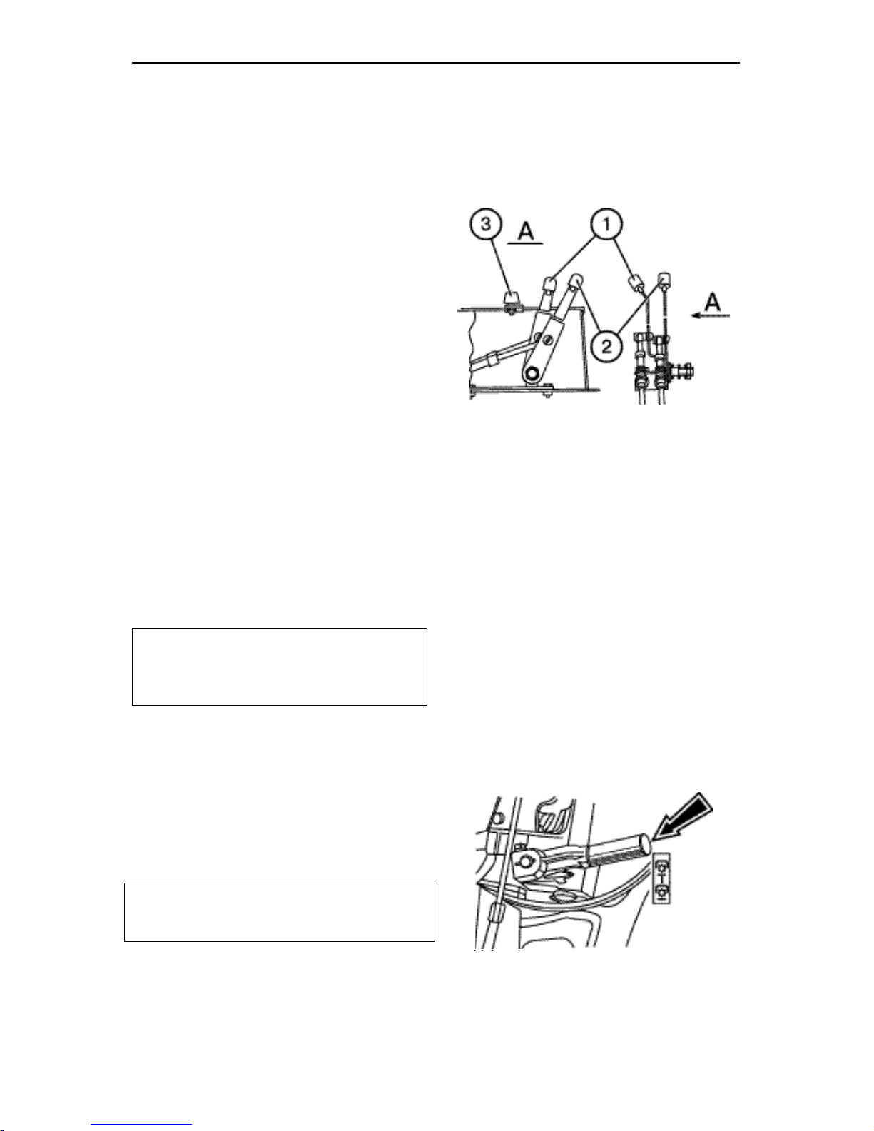
BELARUS-1221.2/1221В.2/1221.3 Operating controls and instruments
61
Hydraulic lift linkage control
The hydraulic lift linkage is controlled using two control levers (1) and (2), located
on the right control board inside the cab.
The draft control lever (2) is the nearest
to the operator's seat and has the following positions:
• Extreme forward — maximum depth
of ploughing (“9”).
• Extreme rearward — minimum depth
of ploughing (“0”). Full range of the
lever's positions is denoted with number from “0” to “10”.
The position control lever (1) has following positions:
• Extreme rearward (“1”) — transport
position of rear lift device.
• Extreme forward (“9”) — minimum
height of the implement above the
ground.
The maximum lifting height of the implement using the lever (1) is eliminated by
adjustable stop (3).
Note: The mixed control is carried out
by means of the limitation of the tillage
depth using the lever (1) during draft
control operations.
Hydraulic system pump control
The control lever has two positions:
• “The pump is engaged” – upper position;
• “The pump is disengaged” – lower position.
Important! Disengage the pump at cold
start or maintenance. Engage the pump
at the engine minimum idle speed only.
Page 63
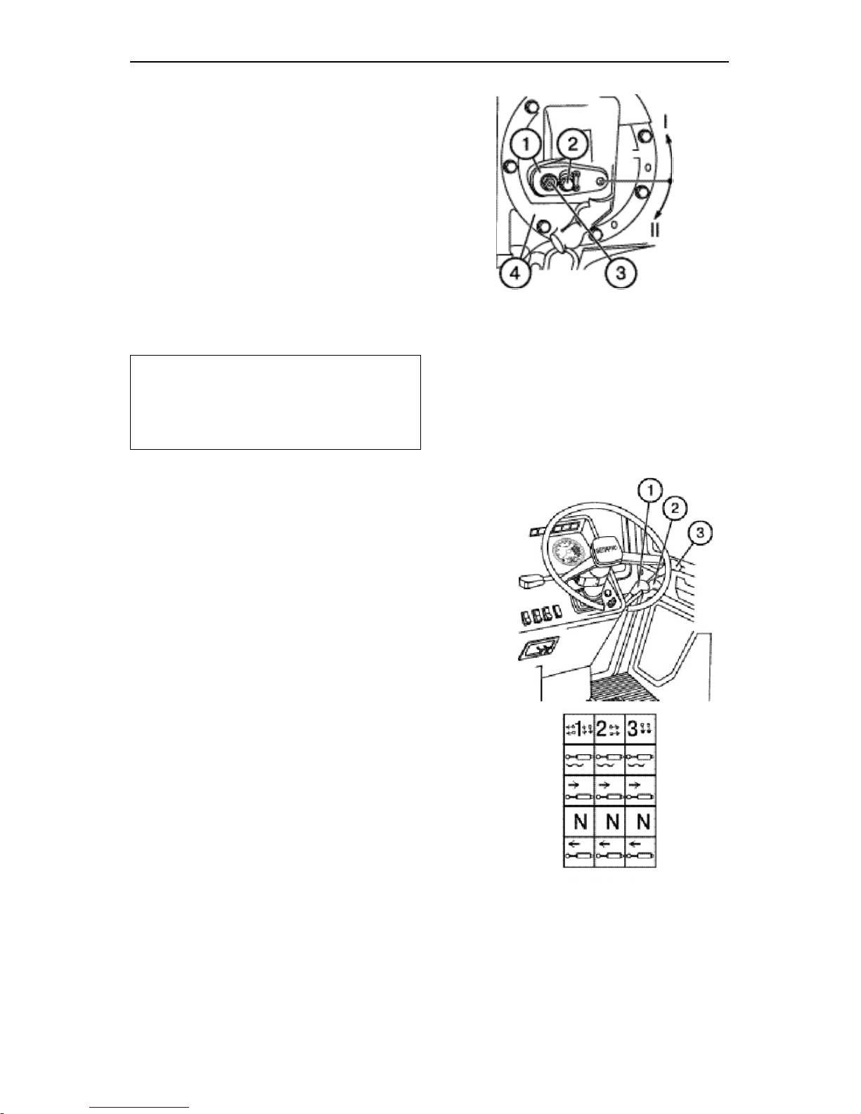
BELARUS-1221.2/1221В.2/1221.3 Operating controls and instruments
62
Gearbox oil pump control
The gearbox oil pump control lever (1)
can have two fixed positions:
I — “Pump drive from engine” (normal
operating position) — the lever (1)
is turned counterclockwise (when
looking at GB from the left tractor
side) relative to the axis (3) until the
lower edge of the lever slot stops
and is fixed by the bolt.
II — non-working position.
Important! Set the lever (1) in the position II when there is a necessity to remove and to mount the assembled GB
pump drive (4) and then fix the lever (1)
in the position I again.
Hydraulic system distributor control
Each of the three remote levers (1, 2, 3),
controls the remote cylinders and has
four positions:
• “Neutral” — low middle (fixed);
• “Lift” — low (non-fixed); after releasing
the lever returns to “neutral";
• “Positive lowering” — upper middle
(non-fixed) between the “float” and
“neutral”. After releasing the lever returns to «Neutral";
• “Float” — upper (fixed)
Page 64
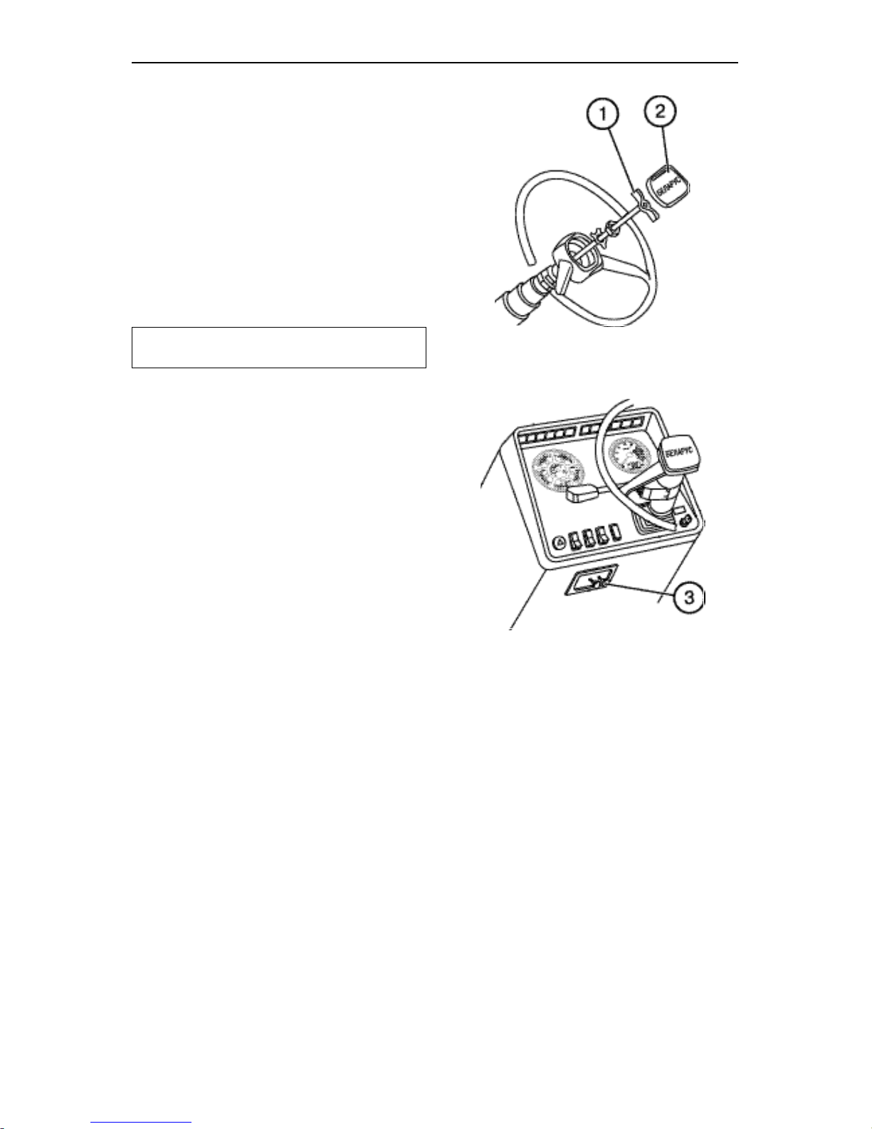
BELARUS-1221.2/1221В.2/1221.3 Operating controls and instruments
63
Changing of steering wheel position
To adjust the height of the steering
wheel, proceed as follows:
• Remove the cover (2);
• Unscrew the clamp (1) for 3…5 turns;
• Set the steering wheel in the required
position;
• Tighten the clamp (1) manually and fix
the cover (2) back.
Note: Steering wheel height adjustment range is 100 mm.
The steering column can tilt to four different positions from 25° to 40° relative
to horizontal line in increments of 5°). In
order to tilt the steering column, pull the
handle (3) on.
Page 65
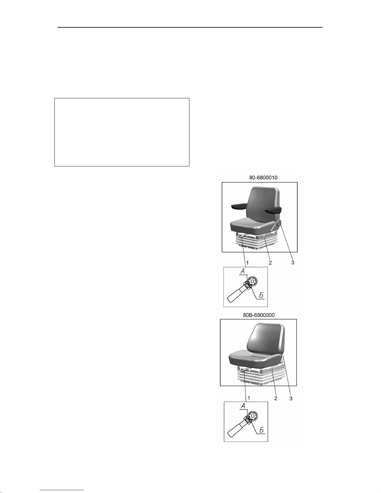
BELARUS-1221.2/1221В.2/1221.3 Operating controls and instruments
64
“BELARUS” 80-6800010/
80В-6800000 seat
The 80-6800010 seat is distinguished
from the 80В-6800000 seat by the
mounting seat and a possibility to complete the 80-6800010 seat with elbows
and a safety belt.
Important! Before operating the tractor
Adj
ust the seat to the most comfortable
position. All adjustments should be made
while sitting in the seat.
The seat is considered correctly adjusted
according to the weight if it moves on the
half of its travel under the operator's
weight (suspension travel is 100mm).
Seat adjustments:
According to the driver's weight from
50 till 120 kg.
Seat adjustments are carried out by the
lever (1). To adjust the seat to larger
weight move the lever pawl (1) to the
position “A” and tight the springs using
to-and-fro motion. To adjust the seat to
the smaller weight move the lever pawl
to the position “B” and release the
springs using to-and-fro motion.
Back inclination adjustment within
the range from 15° to 20°(for the seat
80-6800010).
Carried out by the flywheel (2). To increase the angle of the back inclination
turn the flywheel clockwise, to reduce it
turn the flywheel contraclockwise.
Back inclination adjustment within
the range from 5° to 25°Р (for the seat
80Б-6800000)
Carried out by the lever (2). Lift the lever
upwards to the stop, move the back and
release the lever. The back will be fixed
in the given position.
Longitudinal seat adjustment within
the range of 160 mm.
Carried out by the lever (3). To move
the seat forward/backward pull the lever
upwards, move the seat and release the
lever. The seat is automatically fixed in
the necessary position.
Height adjustment within the range of
60 mm. The seat has three height positions “lower”, “middle” and “upper”. To
move the seat from the “lower” position
to the “middle” one or from the “middle”
position to the “upper” one smoothly lift
the seat upwards to the clickwork (the
indicator click sounds). To move seat
from the “upper” position to the “lower”
one move the seat sharply upwards to
the stop and move down.
Note: It is not possible to move the
seat from the “middle” position to the
“lower” position.
Page 66
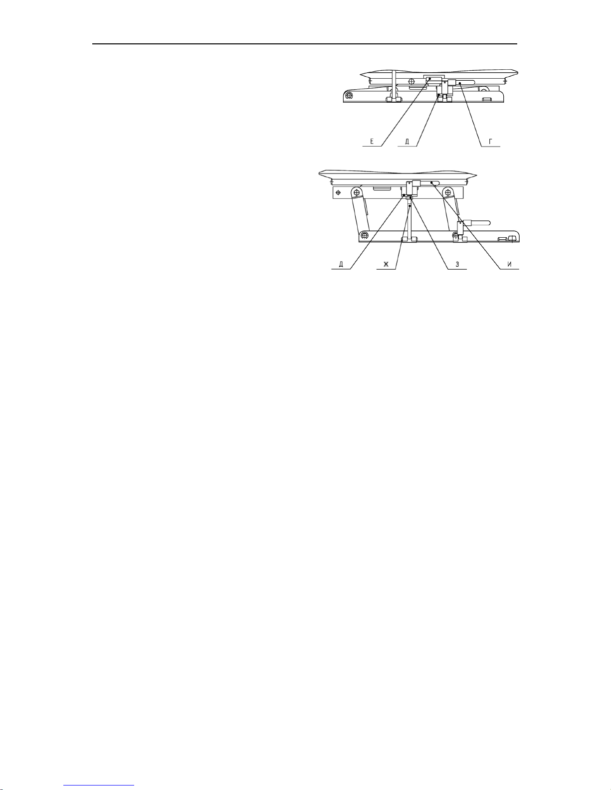
BELARUS-1221.2/1221В.2/1221.3 Operating controls and instruments
65
“Reverse position” (for the trac-
tor with the reverse control panel
“BELARUS-1221В.2”). To set the seat
to the reverse position it is necessary to
turn the clamps “Г” off and move them
out of the panel brackets edges “Д”, lift
the lever “Е” and turn the seat half-way
(180°). Sharply lift and pull it the seat
upwards. Set the screws “Ж” into the
slots of the panel brackets “Д”, put the
screw «З» on in the brackets to the stop
and fasten the clamps “И” with the turning torque 44 … 56 Nm.
Page 67
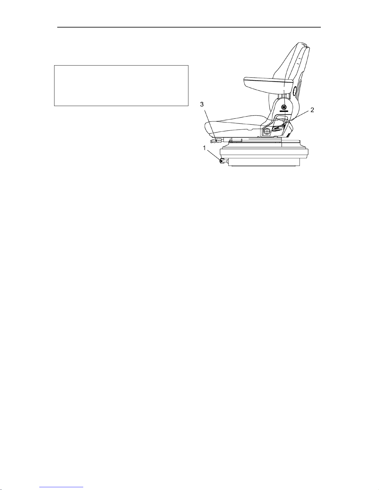
BELARUS-1221.2/1221В.2/1221.3 Operating controls and instruments
66
The seat Grammer MSG85/721
(if installed)
Important! Prior to beginning the operation of the tractor, adjust the seat to the
position being the most con
venient for
you. Perform all the adjust
ments while
sitting on the seat.
Seat adjustments:
According to the driver's weight with-
in the range from 50 to 130 kg with the
mass indication every 10 kg. Carried
out by the lever (1). To adjust the seat to
the bigger weight turn the handle clockwise, to adjust the seat to the lower
weight turn the handle contraclockwise.
Adjustment of back inclination from -
10° до 35°.
Carried out by the lever (2). Lift the lever
upwards to the stop, move the back and
release the lever. The back is fixed in the
necessary position.
Longitudinal seat adjustment within
the range of 150 mm.
Carried out by the lever (3). To move
the seat forward/backward pull the lever
upwards, move the seat and release the
lever. The seat is automatically fixed in
the necessary position.
Height adjustment within the range of
60 mm. The seat has three height positions “lower”, “middle” and “upper”. To
move the seat from the “lower” position
to the “middle” one or from the “middle”
position to the “upper” one smoothly lift
the seat upwards to the clickwork (the
indicator click sounds). To move seat
from the “upper” position to the “lower”
one move the seat sharply upwards to
the stop and move down.
Note: It is not possible to move the
seat from the “middle” position to the
“lower” position.
Page 68
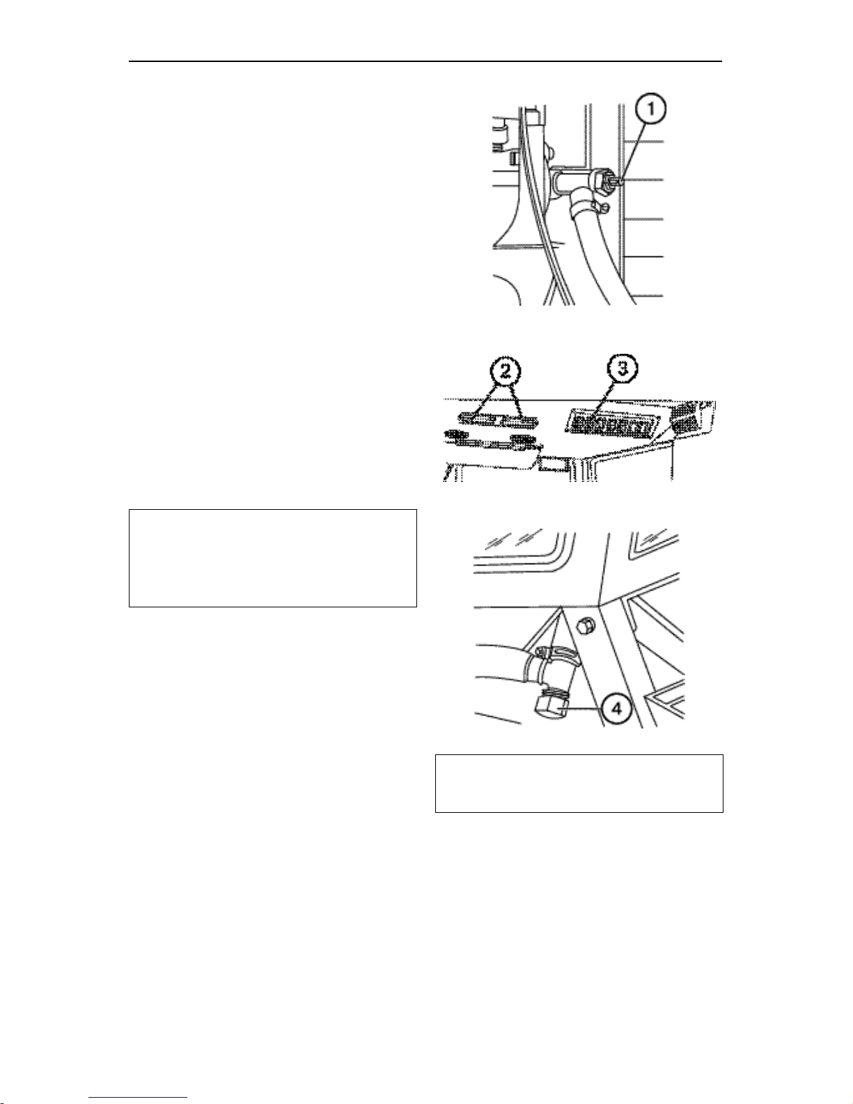
BELARUS-1221.2/1221В.2/1221.3 Operating controls and instruments
67
Cab Heater Control
To put the cab heater into operation,
proceed as follows:
1. Open the cock (1) from the left-hand
side of the engine over fine fuel filter.
Turn the cock handle counterclockwise against the stop. Make sure the
coolant circulates in heater system
slightly turning off the drain plug (4)
from the right-hand side of the cab.
Tighten the drain plug.
2. Turn on the heater fan using the
switch (3), located on the upper panel
of cab roof.
3. By opening or closing recirculation
shutters (2) you can control the
amount of fresh air coming into the
cab from the outside. Adjust the airflow direction through controlled
channels.
Note: If you want to warm-up air in the
cab quickly, open the recirculation
shutters fully and switch the heater fan
to high speed using switch (3).
Drain plugs (4) from the left-hand side
and from the right-hand side of the cab
are provided for system emptying filled
with water in the frost season. To avoid
ice plugs, aerate the system with compressed air, but before it close water
dump valves from water radiator and engine cylinder block and replace the radiator cap.
Note: For vent mode of the system in
the warm season the cock (1) has to
be closed.
Page 69
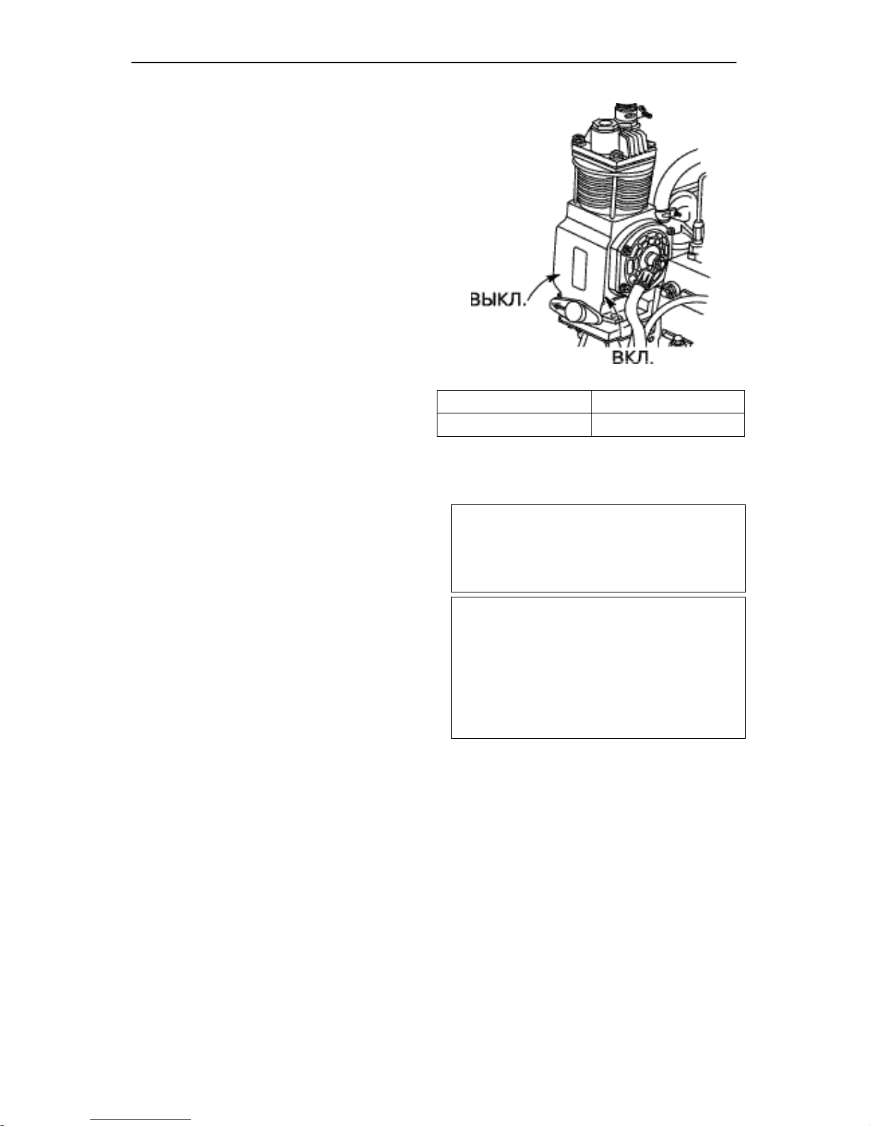
BELARUS-1221.2/1221В.2/1221.3 Operating controls and instruments
68
Pneumatic system compressor control
The handle of compressor control has
two positions:
• “Compressor ON” – when turning
the handle so that the arrow on the
arm is directed backwards to tractor
motion;
• “Compressor OFF” – when turning
the handle so that the arrow is directed forward to tractor motion.
Выкл.
Disengage
Вкл.
Engage
Reversible Control Station BELARUS -1221В.2)
Tractors are equipped with the reversible control station to broaden the possibilities of unitizing with the forwardmounted agricultural machines.
The components of the reversible control station are as follows:
• additional rear-located steering col-
umn with metering pump;
• double foot controls of the engine
throttle, clutch and service brakes;
• mechanism of seat reversal;
• additional horn button and the en-
gine emergency modes indicators.
ATTENTION!
1. Tractor reverse control station intends only for the field operations
at the reverse running.
2. When running at the reverse mode,
lock the standard service brake.
3. Never drive the tractor at the reverse
mode over the general-purpose
roads, during operations, not connected with agriculture, and by lifton/lift-off of the tractor.
Page 70
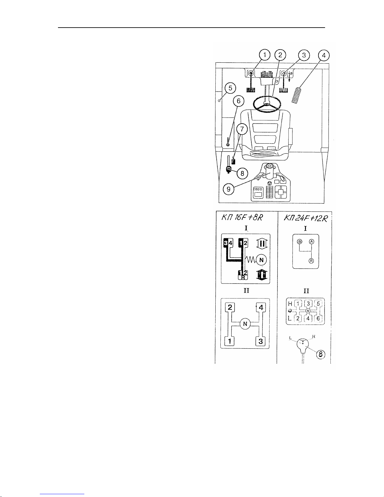
BELARUS-1221.2/1221В.2/1221.3 Operating controls and instruments
69
Reversible station controls.
The additional reverse controls are
located at the rear side of the cab
as shown in the figure below:
1 - the clutch is disengaged when
pressing the pedal. Clutch engagement takes place by pedal
release.
2 –steering wheel of tractor turning
(it is taken from the steering
column of forward motion (9)).
3 –brakes pedal. Both tractor
brakes and pneumatic drive of
trailer brakes are engaged by
depressing the pedal.
4 –foot throttle. Fuel feeding is in-
creased by pressing the foot
throttle.
5 – horn button.
6 –fuel delivery control lever. Ex-
treme rearward position (on re-
verse) corresponds to full fuel
delivery, extreme forward posi-
tion corresponds to engine
stopping.
7 –gearbox ranges selecting lever
(see pattern I).
8 –transmission speed control lever
(see pattern II).
9 –steering column of forward mo-
tion.
To adjust the tractor for reverse
operation, proceed as follows:
• lock the standard brake pedals;
• transfer the steering wheel to the
additional steering column. For that
purpose turn off the handwheel of
the steering wheel fixation, transfer
the steering wheel and fix it at the
required height;
• turn the revolving seat for reverse
operations;
• set the HPS switch cock to the
“reverse” position.
Page 71

BELARUS-1221.2/1221В.2/1221.3 Description and operation
70
DESCRIPTION AND OPERATION
Engine
The tractor is equipped with a Д-260.2/Д-
260.2С/Д-260.2S2 six-cylinder in-line in-
line, four-stroke turbo-charged, directinjection liquid-cooled diesel engine (with
a charge air cooler with coolant for the Д-
260.2S2 engine).
The engine is started by means of an
electric starter.
The engine (Fig. E-1, E-2) consists of a
cylinder block, two cylinder heads, crank
mechanism, valve control as well as feed,
lubrication, cooling and starting systems
and electric equipment.
The cylinder block (20) (Fig. E-1) is designed as a monoblock consisting of a
rigid iron casting.
Six replaceable sleeves (15) made of
special cast iron are installed in the cylinder block bores.
The sleeve is installed in the cylinder
block at two centring ‘belts’. At the upper
belt the sleeve is restrained with a shoulder, while at the bottom one it is packed
with two rubber rings.
From the bottom, the cylinder block is
closed with a crankcase casting (1) made
of aluminium alloy.
The two interchangeable cylinder heads
(18) (one per three cylinders) are iron
cast.
The cylinder head contains the inserted
valve seats made of heat and abrasion
resistant alloy. In the cylinder head, the
injectors (14) (Fig. E-2) (three per head)
are installed.
The provide the tightness of the joint between the cylinder heads and the cylinder
blocks, a gasket (19) made of asbestos-
steel cloth is inserted. The bores for the
cylinder sleeves and the oil passageway
are edged with sheet steel. When assembling the engine at the manufacturing
plant, the cylinder holes in the gasket are
additionally edge-formed with Teflon
rings.
The crank gear (Fig. E-1) includes a
crankshaft (25), together with main- and
connecting-rod bearings, a flywheel (22),
pistons (14) in assembly with piston rings
and pins, and connecting rods (13).
The crankshaft is a steel member made
with counterweights and supported on
seven bearing saddles. Crankpins are
made with pockets intended for additional
centrifugal cleaning of oil. They are
stopped with threaded plugs.
Valve timing drive and oil pump drive
gear as well as a water-pump, alternator
and air-conditioner compressor (if installed) drive pulley are mounted on the
crankshaft front-end.
To reduce the crankshaft torsional vibration amplitude, the pulley is fitted with a
liquid-type torsional vibration damper (3)
(Fig. E-1).
The piston is made of aluminium alloy. A
combustion chamber is made in the piston crown. Three compression piston
rings and one oil ring with an expander
are installed in the upper part of the piston. The top compression piston ring has
a tapered face. A “non-resistive” spacer is
installed under the top ring.
Page 72
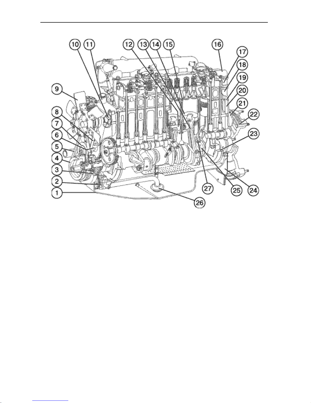
BELARUS-1221.2/1221В.2/1221.3 Description and operation
71
Fig. E-1. Д-260.2 engine (longitudinal section):
1 – crankcase; 1 – oil pump; 3 – vibration damper; 4 – crankshaft pulley; 5 – fan driving belt; 6 – valve-timing
gear cover; 7 – jockey; 8 – alternator driving belt; 9 – fan; 10 – water pump; 11 – thermostat housing; 12 –
piston pin; 13 – connecting rod; 14 – piston; 15 – cylinder sleeve; 16 – cap; 17 – cylinder head cover; 18 –
cylinder head; 19 – cylinder head gasket; 20 – cylinder block; 21 – rear sheet; 22 – flywheel; 23 – counter-
weight; 24 – cover; 25 – crankshaft; 26 – oil pump header; 27 – piston cooling jet
Page 73

BELARUS-1221.2/1221В.2/1221.3 Description and operation
72
The piston pin is a hollow member made
of chrome-nickel steel. Pin axial displacement in the piston-pin bosses is checked
by piston-pin retaining circlips.
The connecting rod is an I-section steel
part, with a bushing pressed into its top
end. To lubricate the piston pin, the connecting rod top end and the bushing are
provided with drilled passages. The bottom end consists of the rod and cap which
bear the same markings. The connecting
rod caps are not interchangeable. Besides, the connecting rods have group
designations of the mass of top and bottom ends; these are marked on the endface of the top rod end. The engine shall
be fitted with connecting rods belonging to
the same group.
The main- and crankpin bearing inserts
of the crankshaft are thin-walled parts
made of bimetal strip. The shells are
manufactured in two sizes as to the inner
diameter, in accordance with the rated diameter of the crankshaft necks.
The flywheel is made of cast iron and
bolted to the crankshaft flange. A steel
gear rim is pressed onto the flywheel.
The valve actuating and timing gear (refer to Fig. E-2) consists of timing gears,
camshaft, inlet and outlet valves, as well
as their fitting and driving parts.
The camshaft (1) is driven from the
crankshaft through the valve timing gears
and rides on four supports.
The tappets (2) are steel members, with
spherical bottoms. The camshaft cams are
made with a slight tilt that forces the tappets to rotate when in operation.
The tappet pushrods (5) are made of a
steel bar. The downwardly concave part of
the tappet and cup the push-rod cup are
hardened.
The valve rocker arms (7) are made of
steel and rocks on rollers installed in supports. The rocker-arm roller is hollow, with
six radial bores for arm lubrication. Displacement of the rocker arms along the
roller is restricted by spreader springs.
The inlet and outlet valves (3) are made
of high-temperature steel and free to
move in their guide bushes. The bushes
are press-fitted in the cylinder heads.
Each valve closes under the force of two
springs: outer (12) and inner (10) fixed on
its stem by means of a valve spring retainer (9) and valve locating split cones
(10).
The sealing collars (18) fitted on the valve
guiding bushes keep oil from leaking down
into the engine cylinders through gaps between the valve stems and guiding
bushes.
Page 74
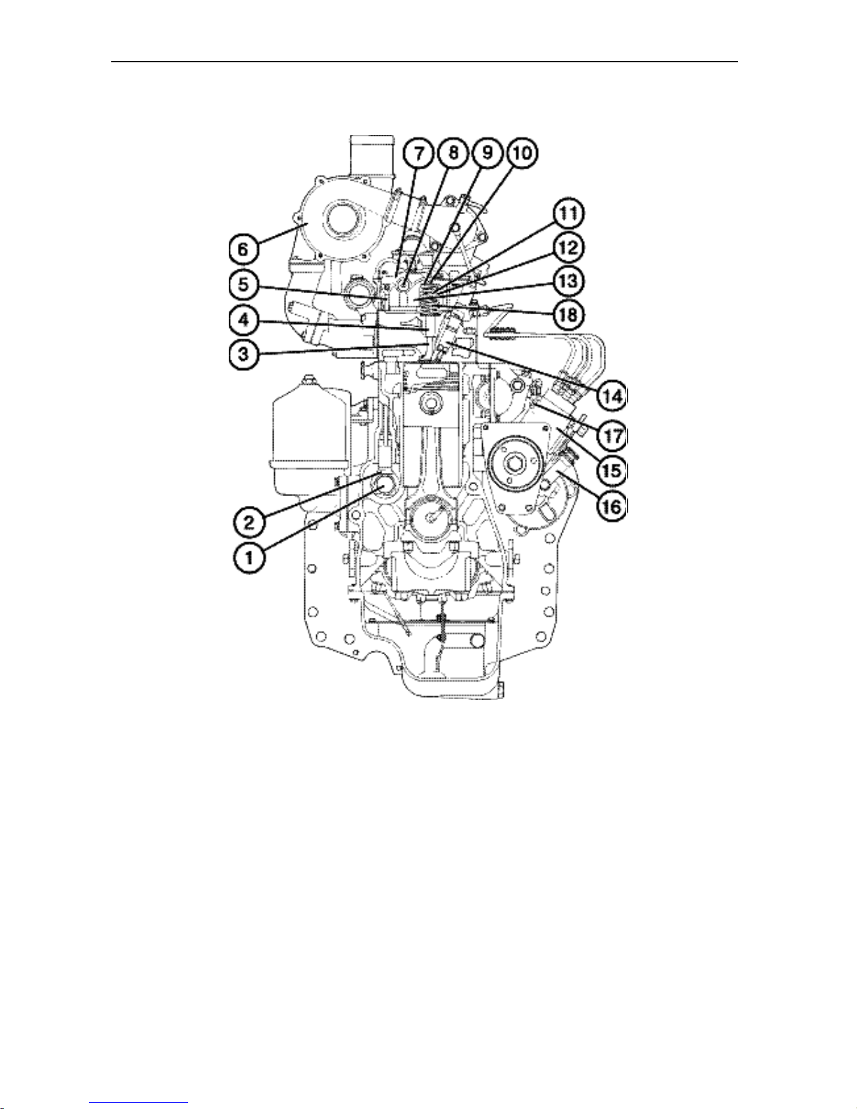
BELARUS-1221.2/1221В.2/1221.3 Description and operation
73
Fig. E-2. Д-260.2 diesel engine (cross section):
1 – camshaft; 2 – tappet; 3 – valve; 4 – valve guiding bush; 5 – pushrod; 6 – turbocharger; 7 – rocker arm; 8
– roller; 9 – spring retainer (disk); 10 – split cones; 11 – inner spring; 12 – outer spring; 13 – support; 14 –
injector; 15 – fuel pump
*)
; 16 – boost fuel hand-pump; 17 – plug to bleed air from the oil pump head; 18 –
sealing collar
*) The distributive-type fuel pump shown in Fig. E-2 is not used at present. The Д-260.2/Д-
260.2С/Д-260.2S2 engines are equipped with in-line pumps Type 363-40 (YAZDA Open
Joint-Stock Company, Russia) or PP6M10P1f (Motorpal, Czechia).
The Д-260.2 engine may be equipped with the РР6М10Р1f-3492 fuel pump manu-
factured by the Motorpal Joint-Stock Company (Czechia).
Page 75

BELARUS-1221.2/1221В.2/1221.3 Description and operation
74
The adjusting parameters of the fuel pumps are shown in the Table below
Parameter description
Unit of measure-
ment
Value
РР6М10Р1f-
3492
(Д-260.2)
1. Average fuel feed per cycle through induction (high-pressure) pipe-
lines, at 100 min-1 rpm, no less than
mm
3
/cycle
150
2. Camshaft rated speed min-1 1050±10
3. Average fuel feed per cycle through pump high-pressure pipelines,
at rated RPM
mm
3
/cycle
80±2
4. Irregular fuel feed through induction pipelines , at rated RPM, no
more than
%
6
5. RPM at regulator action commencement min-1 1080±10
6.Complete fuel-feed cutoff automatically by the regulator – within the
RPM range
min
-1
1170
not more than
7. Average fuel feed per cycle by pump sections, at diesel-engine
speed:
800 min-1
500 min
-1
mm
3
/cycle
83±2.5
70±3.5
8. Pressure at pneumatic adjuster start/end action, at n = 500 min-1
MPa
0.005…0.01
0.025…0.03
9. Average fuel feed per cycle, at 500 min-1 and no-supercharging
pressure condition
mm3/cycle
55.5…64.5
Note: The parameters to be adjusted as per items 3…7 should be checked with the pneumatic ad-
juster arbitrarily disconnected (air pressure in the pneumatic adjuster is 0.05…0.06 MPa).
In case of a difficult engine start or
smoky exhaust, as well as after replacing
or installing the fuel pump after adjustment and/or repair, be sure to check the
timing angle of the fuel pump.
To check the timing angle, proceed
as follows:
- set the regulator control levers to
a position corresponding to maximum fuel
feed;
- disconnect the injection pipeline
from the union of the first pump section;
connect a fuel injection timing meter
(momentoscope) instead (a female-swivel
nut with a short tube coupled through a
rubber pipe with a 1…2-mm inner dia.
glass tube);
- turn the crankshaft clockwise with
the help of a wrench, until fuel free of
bubbles flows from the device glass tube;
- remove some fuel from the glass
tube by shaking the latter;
- turn the crankshaft in the opposite direction (counter-clockwise) through
30…40°;
- observe the fuel level in the glass
tube when rotating slowly the engine
crankshaft; stop the crankshaft rotation
the instant the fuel begins to rise;
- read the position of the locating
pin arrow on the valve control mechanism
cover.
If it is within “21…23” on the
graduated scale located on the vibration
damper housing, then the setting angle of
fuel injection advance is correct, i.e. the
first cylinder piston is in the position corresponding to 21…23° to TDC.
If the arrow is outside the stated
range, proceed with re-adjustment; to do
this:
- bring the locating pin arrow in coincidence with mark “22” of the graduated
scale on the vibration damper housing by
turning the crankshaft;
Page 76

BELARUS-1221.2/1221В.2/1221.3 Description and operation
75
- remove the hatch cover;
- back off 1…1.5 turn three M10
nuts which fasten the fuel-pump drive
gear to the fuel pump drive flange;
- remove some fuel from the injection meter glass tube, if any;
- using a wrench, rotate the fuel
pump shaft by its nut in one and the other
direction within the limits of the slots on
the fuel pump-drive gear surface, until the
injection meter glass tube is full;
- set the fuel pump shaft to its extreme (counter-clockwise) position within
the limits of the slots;
- remove part of the fuel from the
device glass tube;
- rotate slowly the fuel pump shaft
clockwise until the fuel in the glass tube
begins to rise ;
- at the moment when fuel starts to
rise in the glass tube, stop rotation of the
shaft and tighten home the nuts fastening
the gear to the fuel pump drive flange;
- re-check the instant of fuel feed
onset;
- disconnect the injection meter
and replace it with the injection (highpressure) pipeline and fasten the hatch
cover back in place.
Page 77
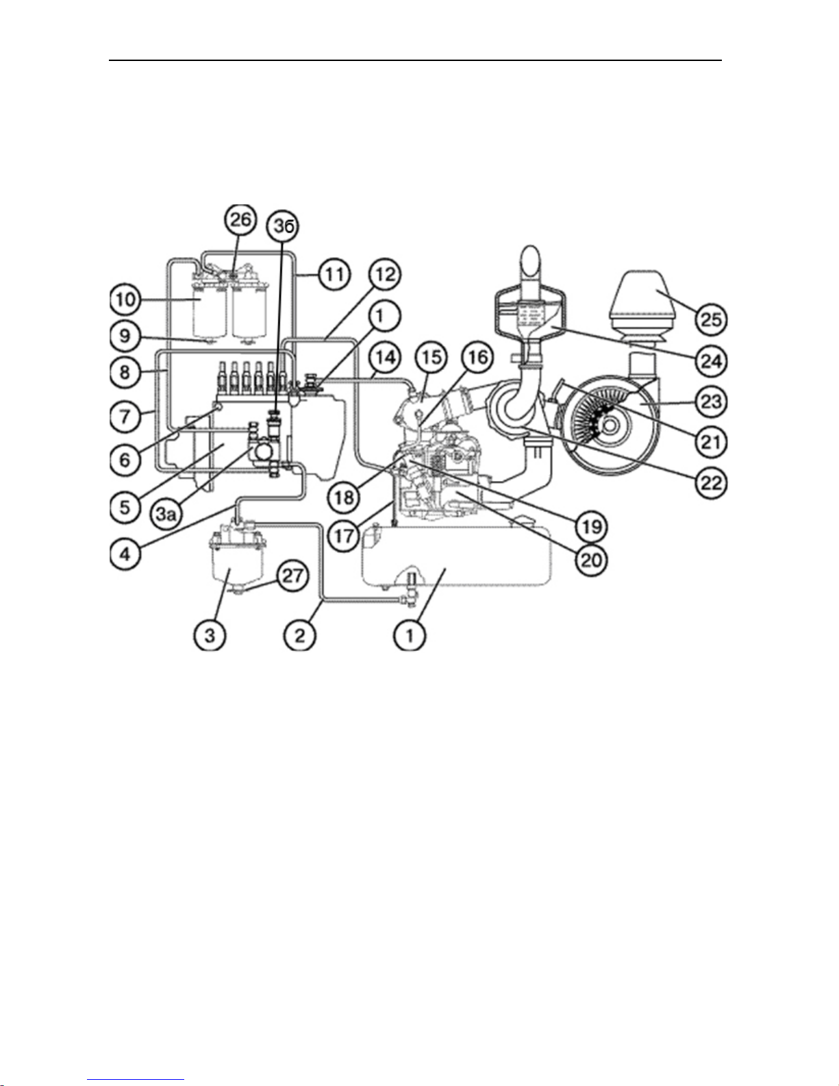
BELARUS-1221.2/1221В.2/1221.3 Description and operation
76
The engine feed circuit (refer to Fig. E-3) consists of an air-cleaner, air-delivery
conduit, induction and exhaust manifolds, turbocharger, exhaust silencer, fuel tank, coarse
and fine fuel filters, fuel pump, injectors, as well as fuel-injection and delivery pipelines.
Fig. E-3. Fuel feed circuit diagram:
1 – fuel tank; 2 – connecting pipe from the fuel tank; 3 – coarse fuel filter; 4 – ; 4 – connecting pipe from the
coarse fuel filter; 5 – fuel pump; 6 – plug to bleed air from the oil pump head; 7 – fuel offtake pipe from the
lower-pressure chamber to the fuel-lift pump; 8 – pipe to deliver fuel from the fuel-lift pump to the fine fuel
filter; 9 – plug to drain sludge; 10 – fine fuel filter; 11 – fuel offtake pipe from the fine filter to the lowerpressure chamber of the pump; 12 – fuel injection pipe; 13 – pneumatic adjuster; 14 – air-delivery pipe from
the turbocharger downstream air-delivery conduit to the pneumatic adjuster; 15 – induction manifold; 16 –
fuel overflow pipe; 17 – fuel drainage pipeline; 18 – fuel overflow pipe; 19 – injector; 20 – cylinder head; 21 –
air-cleaner clogging indicator pipeline; 22 – turbocharger; 23 – air-cleaner; 24 – exhaust silencer; 25 –
coarse air filter (monocyclone); 26 – air-bleeding plug; 27 – plug to drain sludge.
Page 78
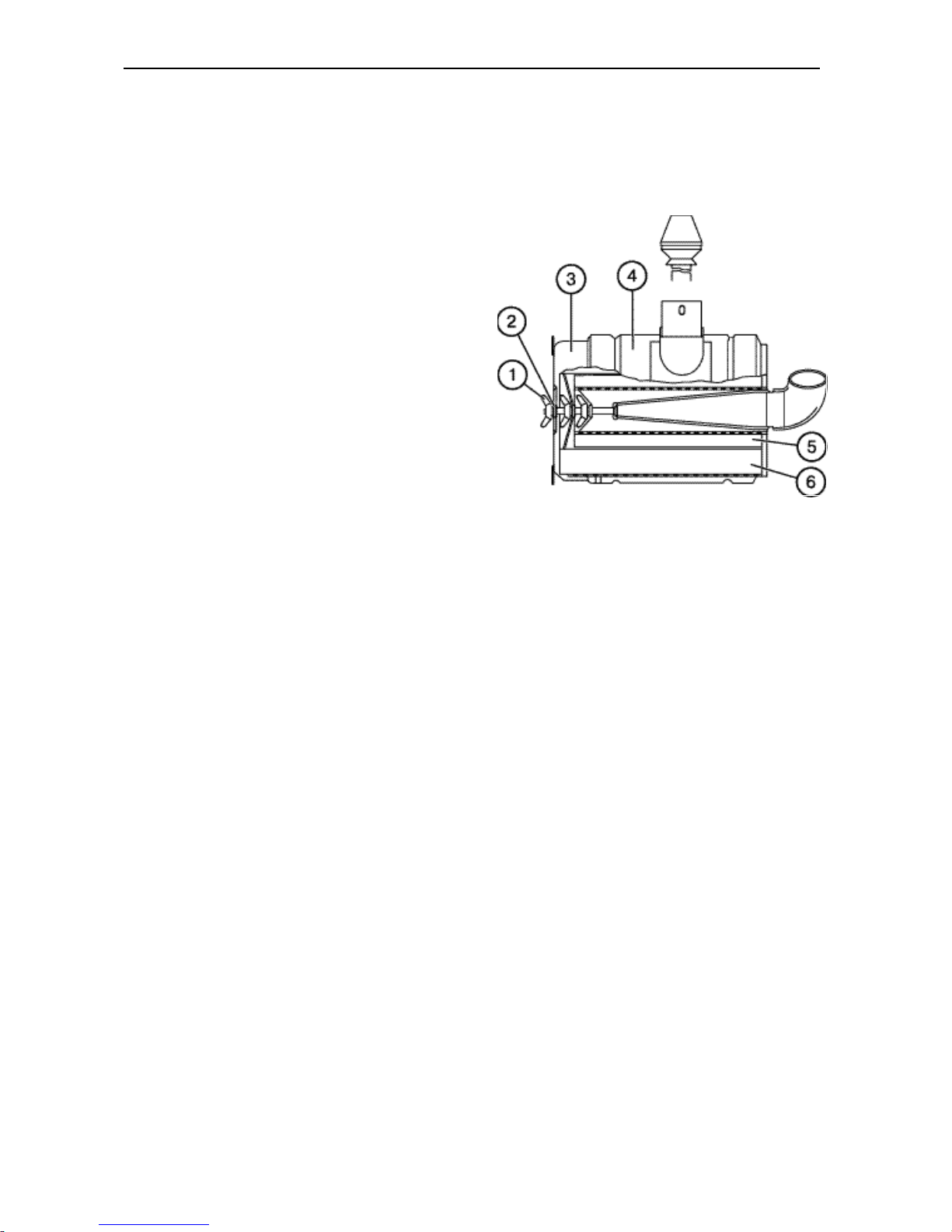
BELARUS-1221.2/1221В.2/1221.3 Description and operation
77
The air cleaner (refer to Fig. E-4) is a drytype filter with paper filtering cartridges. It
provides the three-stage purification. The
first stage – preliminary inertial cleaning;
the second and third – dry cleaning in
master 6 and check 5 paper filtering elements.
To warn of the extent of air-cleaner clogging, a pilot lamp is installed in the instrument panel pilot lamp cluster. The electric
air cleaner clogging sensor operates at
the induction-pipe depression of 650 ± 50
mm of water.
Fuel is to be cleaned from mechanical impurities by a coarse fuel filter (3) (refer to
Fig. E-3) which includes a screening element. Sludge is drained from the filter
through a drainage plug (27) located in the
bottom part of the cup housing.
Fig. E-4. Air cleaner:
1 – winged nut; 2 – washer; 3 – pan; 4 – housing;
5 – check filter element; 6 – master filter element.
The fine fuel filter (refer to Fig. E-3) has a
replaceable filter element which is installed in the filter housing.
The fine fuel filter is intended for multiple
usage, subject to regular replacement of
filter elements and rubber gaskets, and
observance of the operating instructions.
To bleed air from the diesel-engine feed
circuit, the filter housing is provided with a
plug (26), refer to Fig. E-3.
Fuel injection into the cylinders is
achieved by injectors (19) (refer to Fig. E-
3) (ФДМ-22), closed-type, with five-bore
nozzles.
The diesel fuel injection pump (5) (refer to
Fig. E-3) is an in-line type six-plunger
member with a pneumatic anti-smoking
adjuster.
The fuel pump is driven off the crankshaft,
through fuel distribution gearing.
The fuel pump forms an integral unit with
the fully-variable regulator and piston-type
fuel-lift pump.
The regulator houses a fuel supply corrector, automatic fuel-feed enrichment unit
running at start-up revolutions, and an
anti-smoking pneumatic adjuster.
The fuel-lift pump (3a) (refer to Fig. E-3)
is mounted on the fuel injection pump
body and actuated by the camshaft eccentric.
To bleed the air from the feed system, a
hand-
operated piston-type boost pump (3b) is
provided; and a plug (6) serves to bleed
the air from the fuel-pump head.
Fuel supply is controlled by the pedal or
lever.
To stop the engine (also in emergency),
the engine stop handle is provided.
Fuel pump parts are lubricated from the
engine lubrication system.
Page 79
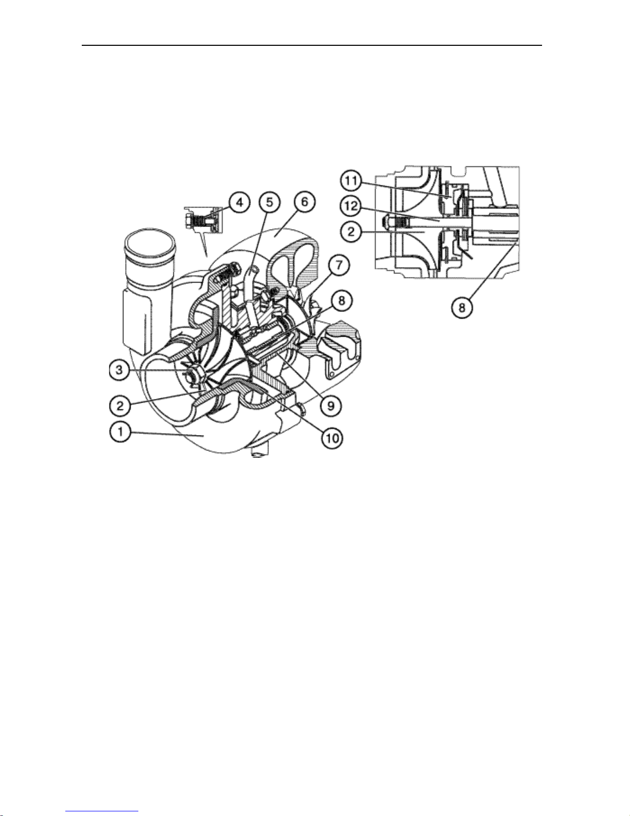
BELARUS-1221.2/1221В.2/1221.3 Description and operation
78
Turbocharger
The turbocharger (refer to Fig. E-6) serves
to charge air into diesel cylinders, using
the energy of exhaust gases. It consists of
a centrifugal one-stage compressor (2)
and a centripetal radial-flow turbine (7)..
The turbine wheel (7) is cast of heatresistant nickel allow and welded to the
rotor shaft (12). The compressor wheel (2)
is an aluminium casting and is attached on
the rotor shaft by means of a special nut
(3).
Fig. E-6. Turbocharger
1 – compressor housing; 2 – compressor wheel; 3 – special nut of the compressor wheel; 4 – fixing nut; 5 –
oil-delivering pipe with a mounting flange; 6 – turbine body; 7 – turbine wheel; 8 – bearing; 9 – intermediate
body; 10 – diffuser; 11 – disk; 12 – shaft
The principle of operation of the turbocharger is that exhaust gases from the cylinders enter the gas-turbine chamber from
the exhaust manifold. While expanding,
the gases rotate the turbine wheel together with its shaft, the other end of
which is fitted with the compressor wheel.
From the turbine, the gases are discharged into the atmosphere through an
exhaust pipe.
The air pressure differential downstream
the compressor in the rated mode of the
engine running shall be 0.05…0.08 MPa
(0.5…0.8 kgf/cm2).
Installation of the charge air cooler
(CAC) (BELARUS-1221.3)
The charge air cooler (13) (Fig. E-7) is installed in front of the water radiator (14)
and connected to the turbocharger (15)
and the engine induction manifold (16)
through a system of air-ducts (1, 4, 10)
and junction branch-pipes (3, 5, 11).
The CAC is designed as an air-to-air heat
exchanger consisting of a core member in
the form of ribbed tubes, reservoirs, and
junction branches. Air is delivered from
the turbocharger to the CAC, cools in the
latter, thus, improving the power and economic as well as ecological characteristics
Page 80
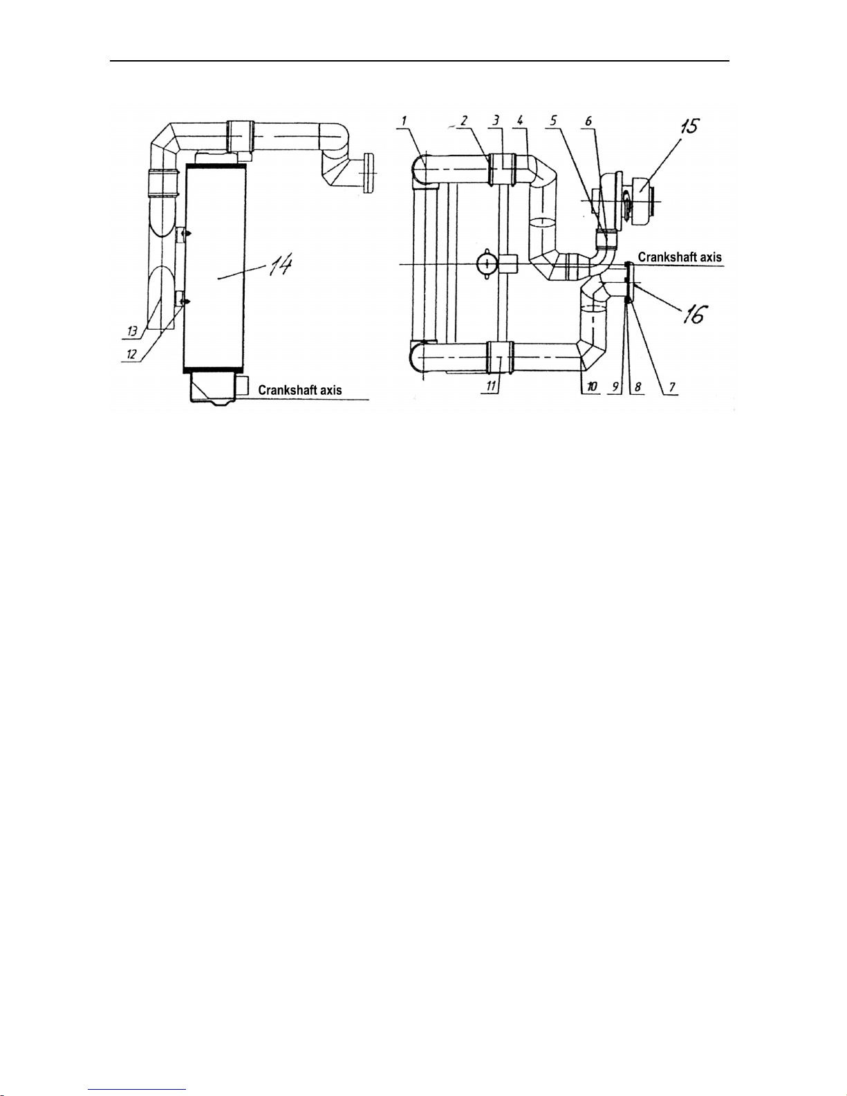
BELARUS-1221.2/1221В.2/1221.3 Description and operation
79
of the engine, and flows to the diesel suc- tion manifold.
Fig. E-7. CAC outfit:
1, 4, 10 – air ducts; 2, 6 – clamp; 3, 5, 11 – junction branch-pipes; 7 – gasket; 8 – washer; 9 – bolt M8x16; 12
– nut; 13 – cooler (CAC); 14 – water radiator; 15 – turbocharger; 16 – engine induction manifold.
The engine lubrication system is combined: some parts are force-lubricated, the
others are splashed lubricated. The system comprises an oil pump, oil filter with a
paper filter element, centrifugal oil pump,
and an oil-to-liquid heat exchanger. The
lubrication system diagram is shown in
Fig. E-8.
The oil pump (20) is a gear-type, singlestage unit driven from the crankshaft. It is
provided with an overflow valve which
opens at a pressure of 0.7…0.75 MPa
(7…7.5 kgf/cm2) and passes oil from the
discharge chamber into the suction chamber.
The oil filter is of the single-flow type, with
a paper filter element. The filter is provided with an overflow valve (1). The valve
opens in case of excessive clogging of the
filter element as well as when attempting
to start a cold engine and returns oil into
the main pipeline while bypassing the filter
element. This valve is not adjustable. Besides, the filter is provided with a relief
valve (21) adjusted to maintain a pressure
within 0.28…0.45 MPa (2.8…4.5 kgf/cm2)
limits in the lube system.
With the engine running, oil, filtered and
cooled in the oil-to-liquid heat exchanger
(3), is supplied to all the bearings of the
crankshaft and camshaft through the passageways in the cylinder block. The pistons (15) are cooled through the nozzles
(16) built into the engine block main journals. For lubricating the turbocharger (7)
and compressor (9) of the tractor pneumatic system, oil is delivered via separate
pipes downstream of the heat exchanger
(3).
Page 81
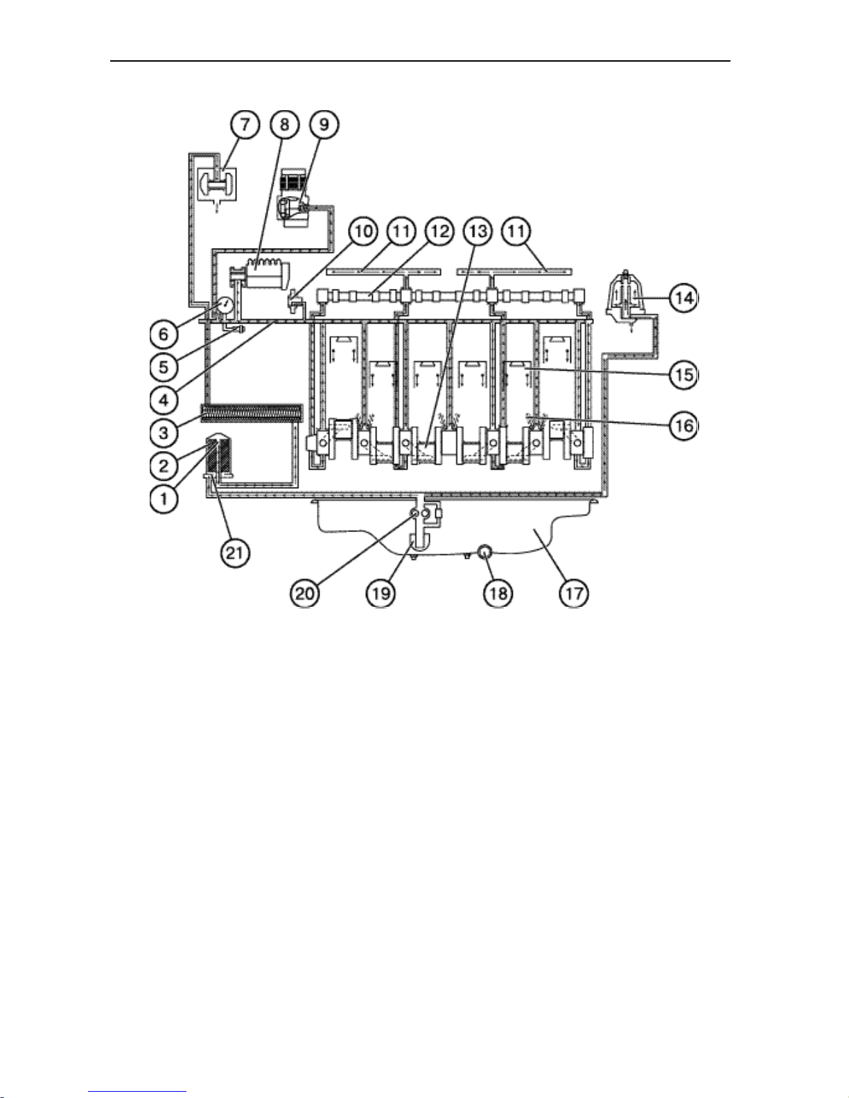
BELARUS-1221.2/1221В.2/1221.3 Description and operation
80
Fig. E-8. Lubrication system diagram:
1 – overflow valve; 2 – oil filter, paper; 3 – heat-exchanger; 4 – main oil pipeline; 5 – oil pressure sensor; 6 –
manometer; 7 – turbocharger; 8 – fuel pump; 9 – compressor of the pneumatic system; 10 – intermediate
pinion; 11 – oil passageway to rocker arm axle; 12 – camshaft; 13 – crankshaft; 14 – centrifugal oil filter; 15 –
piston; 16 – cooling nozzle; 17 – oil pan; 18 – drain plug; 19 – oil pickup; 2 – oil pump; 21 – relief valve.
Page 82

BELARUS-1221.2/1221В.2/1221.3 Description and operation
81
The engine cooling system is of a liquid
closed type, with forced circulation of the
coolant. The system consists of a cooling
jacket, water pump, radiator, fan with
automatically controlled viscous coupling,
two thermostats, expansion tank, connecting hoses and drain cocks.
Thermal state of the diesel is regulated by
changing the air flow passing through the
cooling system radiator as well as by
means of two thermostats.
The coolant temperature is monitored by
the temperature indicator and light alarm
whose sensors are located in the thermostat covers. The normal heat condition of
the engine corresponds to the coolant
temperature of 80…97°C.
The engine lubricating oil is cooled in an
oil-to-liquid heat-exchanger built into the
engine block. To control the oil pressure,
the sensors of oil pressure gauge and
pressure warning indicator installed in the
heat-exchange pipe tap are used. The
normal engine heat condition as to lubricating oil is within 80…120°C.
The radiator is of finned tubular design. A
steam valve in the radiator filler neck
maintains the pressure within 0.045…0.05
MPa (0.45…0.50 kgf/cm2), while an air
valve monitors the vacuum within
0.008…0.01 MPa (0.08…0.10 kgf/cm2).
The fan runs in the two operating modes:
• automatic;
• forced.
The automatic mode is provided through a
viscous friction coupling (12) (refer to Fig.
E-8) as follows: at the coolant temperature
below 80°C the return spring (7) holds the
valve (10) closed; viscous liquid flows over
to the clutch reserve cavity; the driving
(11) and driven (13) disks are rotating with
a gap in-between and, thus, ensure the
fan switched-off state (in this case, the fan
rotational frequency shall not exceed
1,500 rpm).
At the diesel coolant temperature exceeding 80°C, the thermosensitive element
opens the valve (10) acting through the
rod (17) and pusher (9) against the force
of the return spring (7). The viscous liquid
flows over into the head cavity through a
hole in the driving disk and fills in the gap
between the driving and driven disks, with
the result that the disk are engaged, and
the fan is turned on in its normal operating
duty.
Attention: With the compressor running, the forced mode of fan operation
shall be chosen.
To switch over the fan to the forced (con-
tinuous) operation mode proceed as follows:
• screw out the nut (4) of the stop (5) by
4…5 turns (about 5 mm);
• turn the fan by hand so that the stop (5)
would enter the hole (3) in the driving
disk (11). To lock the driving and driven
disks, press the stop (5) by hand.
Page 83
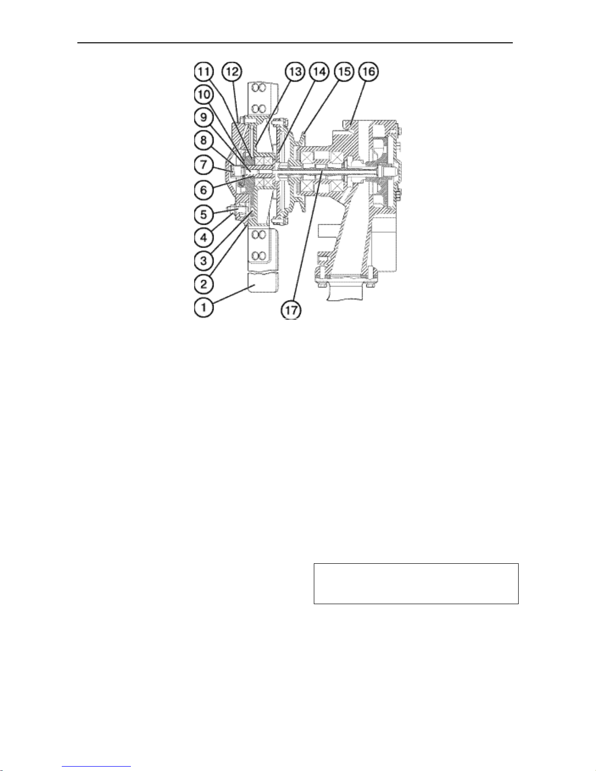
BELARUS-1221.2/1221В.2/1221.3 Description and operation
82
Fig. E-9. Pump assembled with the clutch:
1 – fan blade; 2 – driven cover; 3 – hole for stop; 4 – stop nut; 5 – stop; 6 – stem; 7 – return spring; 8 –
spring holder; 9 – pusher; 10 – valve; 11 – driving disk; 12 – clutch; 13 – driven disk; 14 – drive shaft; 15 –
water pump pulley; 16 – water pump; 17 – rod.
Electrical Equipment and the Starting
System
One of electric assembly units to be installed on the engine is an 1150 W 14 V
alternator represented by a contactless
five-phase homopolar generator with oneend magnet excitation, built-in rectifier
unit and integral voltage regulator. The
alternator is driven from the crankshaft
pulley, with a V-belt.
The engine is started by a 5.5 kW 24 V
electric starter. The starter is switch on
remotely, by means of an electromagnetic
relay and starter switch.
To facilitate the engine starting at low
temperature, the remotely-controlled glow
plugs are used installed in the cylinder
heads. The plugs, when switched on,
heat the air sucked into the cylinders.
Compressor of the pneumatic system
To ensure the reliable operation of the
tractor pneumatic system, the engine is
equipped with a single-piston, singlestage compressor. The compressor is
mounted on the fuel distribution unit cover
flange and driven from the fuel-pump
drive gear.
Note: With the compressor running, the
forced mode of fan operation shall be
chosen.
Page 84
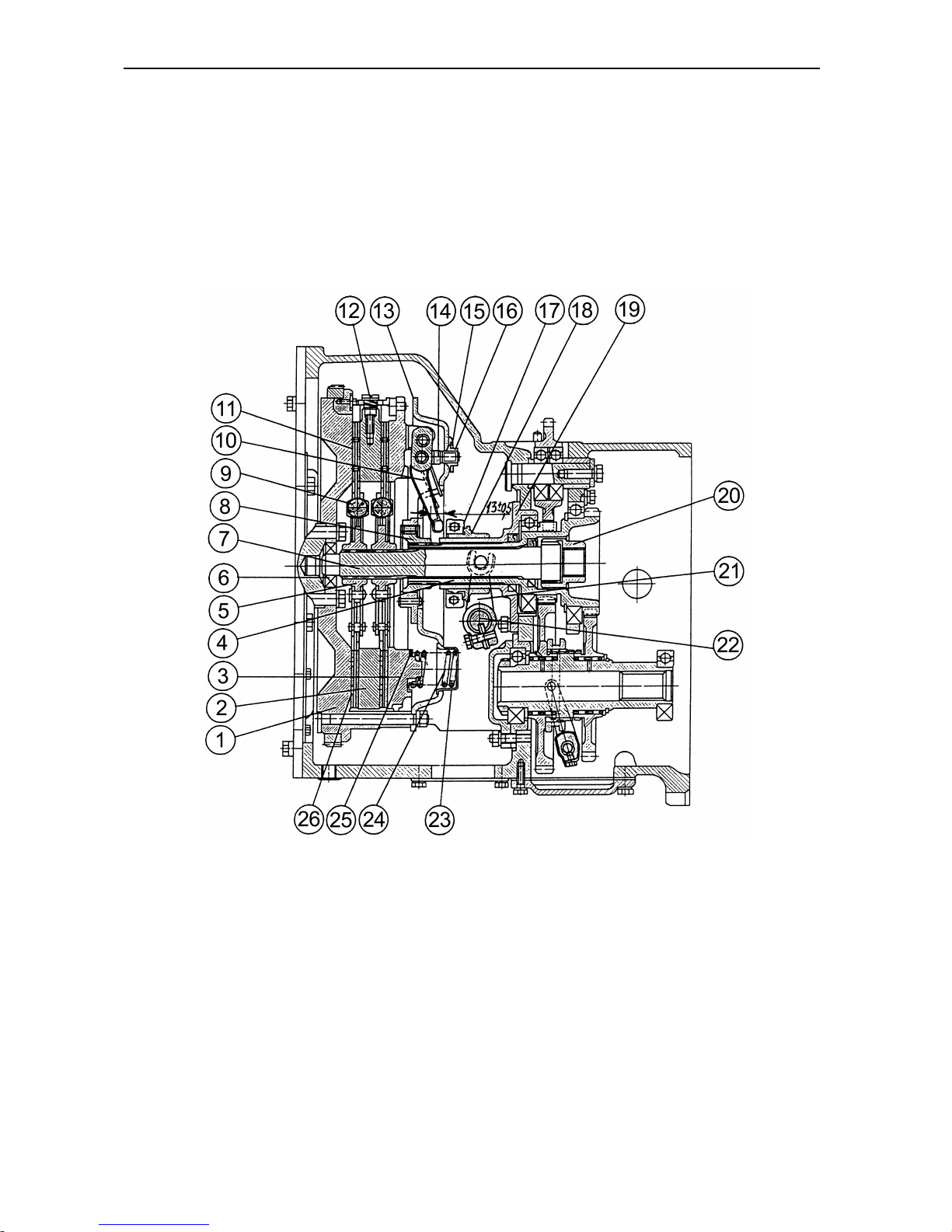
BELARUS-1221.2/1221В.2/1221.3 Description and operation
83
Power Transmission Train
The power train incorporates a clutch,
transmission gearbox, FDA drive, FDA,
and rear axle. It serves to transmit torque
from the engine crankshaft to the front and
rear wheels.
Clutch
The clutch (Fig. E-10) is of friction, doubledry-disk, permanently closed type.
Fig. E-10. Clutch:
1 – flywheel; 2 – intermediate disk; 3 – pressure disk; 4 – input shaft; 5 – clutch hub; 6 – bearing; 7 – power
shaft; 8 – hub; 9 – vibration damper; 10 – release lever; 11 – friction pad; 12 – leverage; 13 – bearing disk;
14 – fork; 15 – washer; 16 – adjusting nut; 17 – throw-out bearing; 18 – retractor; 19 – bracket; 20 – coupling
bushing; 21 – fork; 22 – fork control axle; 23 – shell; 24 – pressure spring; 25 – heat-insulation liner; 26 –
driven disk.
Page 85
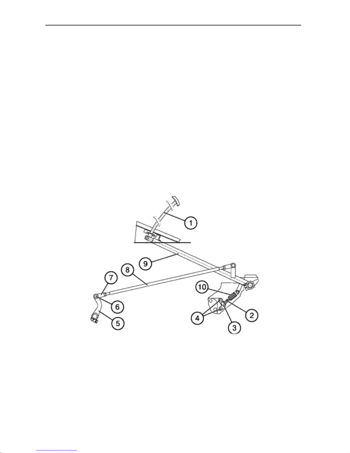
BELARUS-1221.2/1221В.2/1221.3 Description and operation
84
The driving parts of the clutch are the flywheel (1), pressure disk (3), and the intermediate disk (2) with three spikes on its
surface which enter special slots of the
flywheel. Two driven disks (26) together
with vibration dampers (9) mounted on the
power shaft (7) form the clutch driven unit.
Nine pressure springs (24) ensure the required thrust force on the friction surfaces
of the driving and driven units of the clutch
to deliver engine power to the transmission.
The intermediate disk (2) has leverages
(12) which provide automatic adjustment
of its position when disengaging the
clutch.
Forks (14) give support to the release levers. The forks are attached to the bearing
disk by means of adjusting nuts (16) fixed
with washers (15).
Clutch control (BELARUS-
1221.2/1221.3)
The clutch is disengaged by stepping on
the clutch pedal (1) (Fig. E-11) which acts
through the linkage (1), (8), (5) onto the
retractor (18) (Fig. E-10) and the throw-out
bearing (17).
When the pedal (1) is released (Fig. E-
11), the clutch is engaged by the pressure
springs (24) (Fig. E-10). The spring (10) of
the servounit (Fig. E-13) makes the clutch
engagement easier and always presses
the lever (9) against the cab floor when
the clutch is engaged.
Fig. E-11. Clutch control:
1 – pedal; 2 – servounit adjusting bolt; 3 – bracket; 4 – fastening bolt; 5 – lever; 6 – pin; 7 – fork; 8 – rod; 9 –
lever; 10 – servounit spring.
Page 86
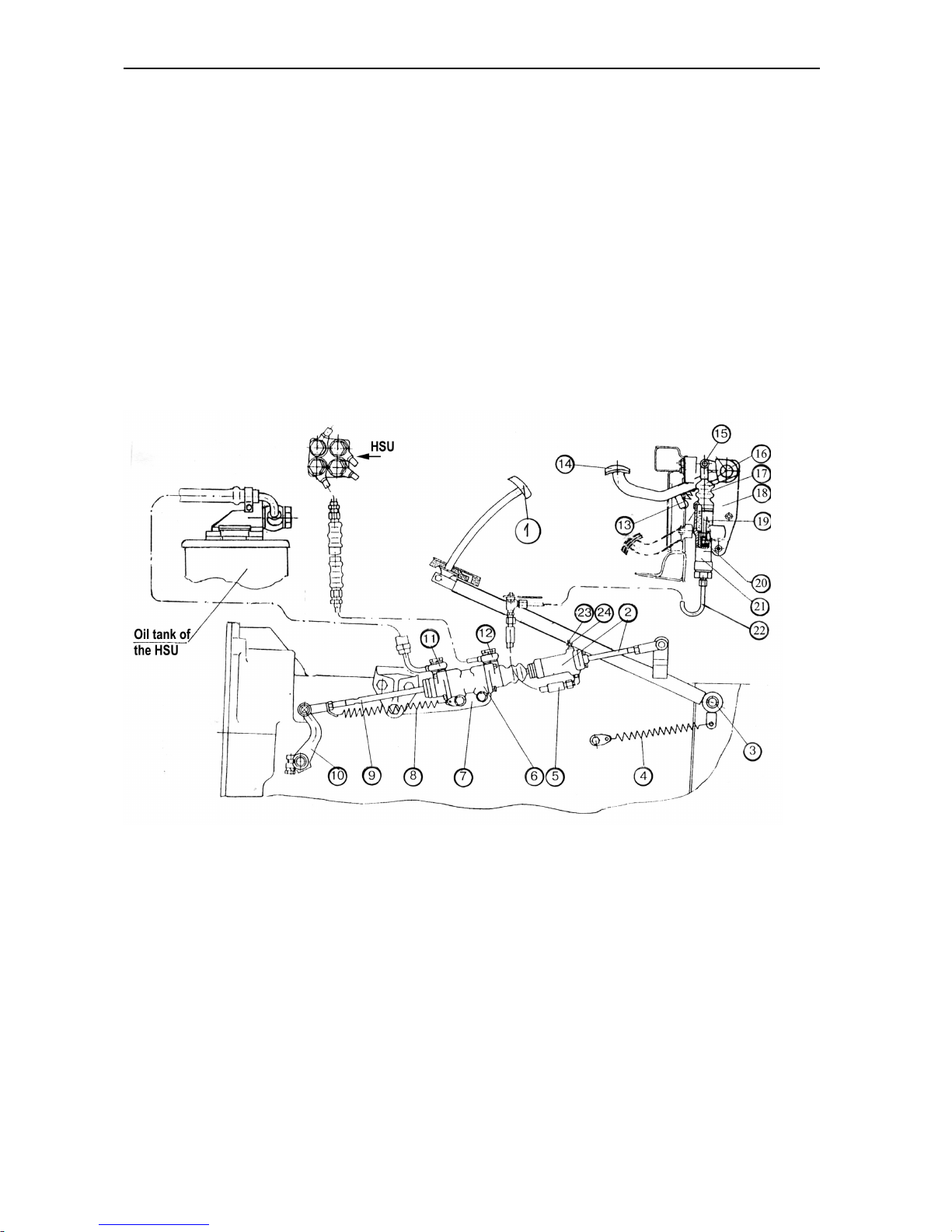
BELARUS-1221.2/1221В.2/1221.3 Description and operation
85
Clutch control (BELARUS-1221В.2)
I. Forward run
The clutch is disengaged by stepping on
the pedal (1), Fig. E-11а acting upon the
operating cylinder (2) of the hydraulic
booster (6) and then upon the rod (9) and
lever (10) of the shaft of the clutch disengagement forks. The hydraulic booster
reduces the efforts needed to press the
pedal when disengaging the clutch; also,
it controls the travel of the lever (10) in
proportion to that of the pedal.
On releasing the clutch pedal, all the
clutch control components return to their
initial position by the force of contracting
springs (4, 8). To operate the hydraulic
booster, a discharged oil flow is used
supplied from the HSU metering pump
through pipeline (12). After the hydraulic
booster the oil is drained in to the HSU
reservoir via the discharge oil pipeline
(11).
With the engine inoperative, the control
train functions as a mechanical one (Fig.
E-11).
Fig. E-11а. Clutch control of a reversible tractor:
1 – clutch pedal; 2 – operating cylinder with a rod; 3 – axle; 4, 8 – contracting spring; 5 – hose; 6 – hydraulic
booster; 7 – bracket; 9 – rod; 10 – lever; 11 – discharge oil pipeline; 12 – delivery pipeline; 13 – backward
spring; 14 – overhung pedal; 15 – pin; 16 – axle; 17 – boot; 18 – bracket; 19 – piston rod; 20 – piston; 21 –
master cylinder; 22 – oil pipeline; 23 – cap; 24 – overflow valve.
II. Reverse.
The hydrostatic drive consisting of an
overhung pedal (14) with backward spring
(13), master cylinder (21), oil pipeline
(22), and operating cylinder (2) with a rod
is used in this case.
The clutch is disengaged by means of the
pedal (14) which acts on the piston rod
(19) and piston (20) of the master cylinder. Under the action of the piston, the
fluid passing through the oil pipe (22) and
hose (5) causes the hydraulic booster (6)
pushrod to move and, thus, to release the
clutch in the manner described for the
forward run of the tractor. As this takes
place, the body of the service cylinder (2)
and the rod as well as the pedal (1) remain stationary in the initial position.
Page 87
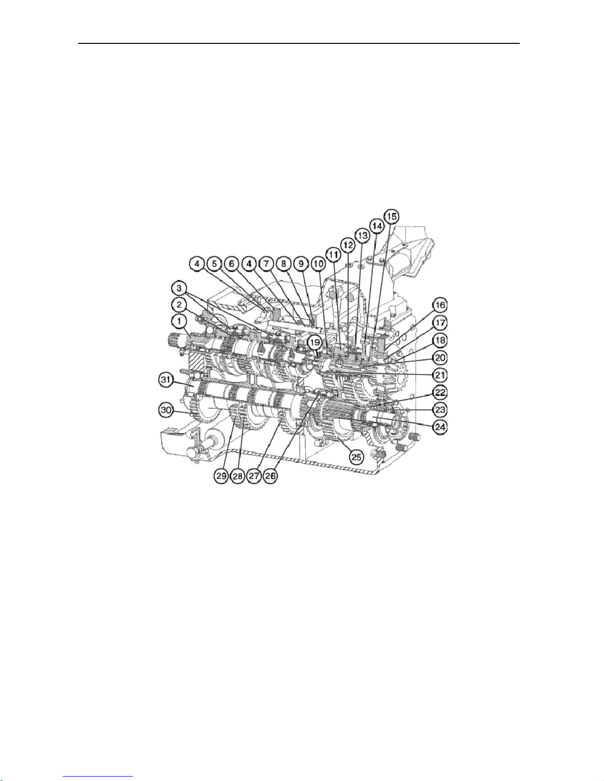
BELARUS-1221.2/1221В.2/1221.3 Description and operation
86
Clutch casing
The clutch casing houses drives of a continuous PTO, HLL oil pump, and oil pump
of the transmission gearbox hydraulic system.
Transmission gearbox (GB) (16F+8R)
The transmission gearbox (Figs. E-12, E-
14) is a 16/8 mechanical-type fixed-ratio
unit (4 forward and 2 reverse gear ranges)
with the intra-range gear shifting by
means of synchronizers. The GB provides
16 forward and 8 reverse speeds as well
as FDA and synchronous PTO drive. The
GB consists of housing, speed-gear assembly, downshift gear shaft and reverse
gear, gear cluster, secondary gear-shaft,
control mechanism, and the GB hydraulic
system.
Fig. E-12. Transmission gearbox:
1 – primary shaft; 2, 20 – bushings; 3 – synchronizer; 4 – forks; 5, 7 – dog; 6 – fork assembly; 8 – ball; 9 –
spring; 10, 17 – bearings; 11, 14, 15, 22, 23, 25, 27, 28, 29, 30 – gears; 12 – half-coupling; 13, 26 – toothed
couplings; 16, 21 – adjusting shims; 18 – secondary shaft; 19 – nut; 24 – gear-cluster shaft; 31 – intermedi-
ate shaft
Page 88
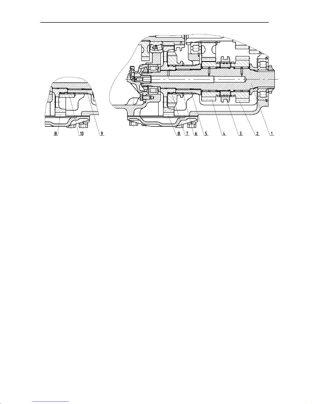
BELARUS-1221.2/1221В.2/1221.3 Description and operation
87
Fig. E-12.2. Shaft of downshift gears:
1 – primary shaft; 2, 4, 7, 8 – gears; 3 – coupling; 5, 9, 10 – bushings; 6 – retaining ring
The speed-gear assembly consists of a
primary shaft (1) (Fig. E-12.1) in assembly with free needle bearing-mounted
gears. The male splines carry two splined
bushings (2) with inertia-type cone synchronizers (3) mounted thereon.
The driven gears (27,28,29,30) are fitted
on the intermediate shaft (31) with slight
interference.
The gears (22) and (25) are fitted on the
gear-cluster shaft (24). The rear shaft
bearing is located in the gear (23) boss of
the synchronous PTO and FDA drive.
The secondary gear-shaft (18) is installed
in the GB housing on the tapered roller
bearings (10) and (17). The FDA driving
gear (15) is fitted immovably on the shaft.
The boss of this gear houses a driven
gear (14) on needle bearings. The bushing (20) carries a driven gear (11) on its
boss. The half-coupling (12) is mounted
between the gears (11) and (14) on the
shaft (18) splines. The entire set of parts
on the shaft (18) is tightened up by the
nut (19).
The gear (4) of the 1st and 2nd ranges and
the gear (2) of the reverse are fitted on
the shaft of downshift gears and reverse
(1) (Fig. E-12.2). The gear (8) is mounted
on the shaft by means of a bronze bushing. Depending on the standard equipment of the gearbox, the design of the
shaft of downshift gears differs as follows:
1) if the gearbox provides for the
possibility of installation of the
speed-reduction gear, the
splined bushing (5) is fitted with
the speed-reduction gear wheel
(7) connected with the splines of
the gear (8) and fixed by means
of the retaining ring (6) on the
bushing (5);
2) if the gearbox does not provide
for the possibility of installation of
the speed-reduction gear, the
splined bushing (9) is fitted with
the bushing (10) connected with
the gear (8) through the splines
and fixed by means of the retaining ring (6) on the bushing (9).
Page 89
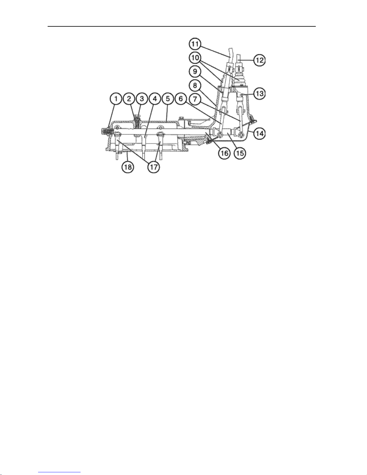
BELARUS-1221.2/1221В.2/1221.3 Description and operation
88
Fig. E-13. Synchronized transmission gearbox control mechanism:
1 – stop; 2 – ball; 3 – spring; 4 – arm; 5 – cover; 6, 7 – levers; 8 – casing; 9 – sphere socket; 10 – boot; 11 –
speed-range change-over fork; 12 – gear shifting fork; 13 – spring; 14 – cover; 15, 16 – shafts; 17 – arms; 18
– gear gate.
GB control mechanism
The GB control mechanism (Fig. E-13)
comprises the gear-shift and speed-range
change-over mechanisms. The gear-shift
mechanism is installed in the fork member (6) (Fig. E-12) and in the casings (5)
and (8) (Fig. E-13). The engagement is
achieved through the lever (7), shaft (15)
and arm (4). The dogs (5) and (7) are installed in the fork member (6) (Fig. E-12)
with the forks (4) fixed thereto. To exclude simultaneous engagement of two
speeds, the locking balls are located between the dogs (5) and (7). To hold the
forks (4) in the neutral and engaged posi-
tions, the spring-loaded ball-point locks
(8) are provided.
The speed-range change-over mechanism consists of a fork (11) of the range
change-over handle, lever (6), shaft (16)
and arms (17) located in the bodies (5)
and (8) as well as parts installed in the
transmission gearbox casing.
The toothed couplings (13, 26) (Fig. E-
12.1) and (3) (Fig. E-12.2) are moved by
forks (1, 4, 14) (Fig. E-14) attached on
the dogs (2, 5, 15), respectively. The
toothed couplings (13, 26) (Fig. E-12.1)
and (3) (Fig. E-12.2) are fixed in neutral
and engaged positions by the parts (8,
11, 12) (Fig. E-14).
Page 90
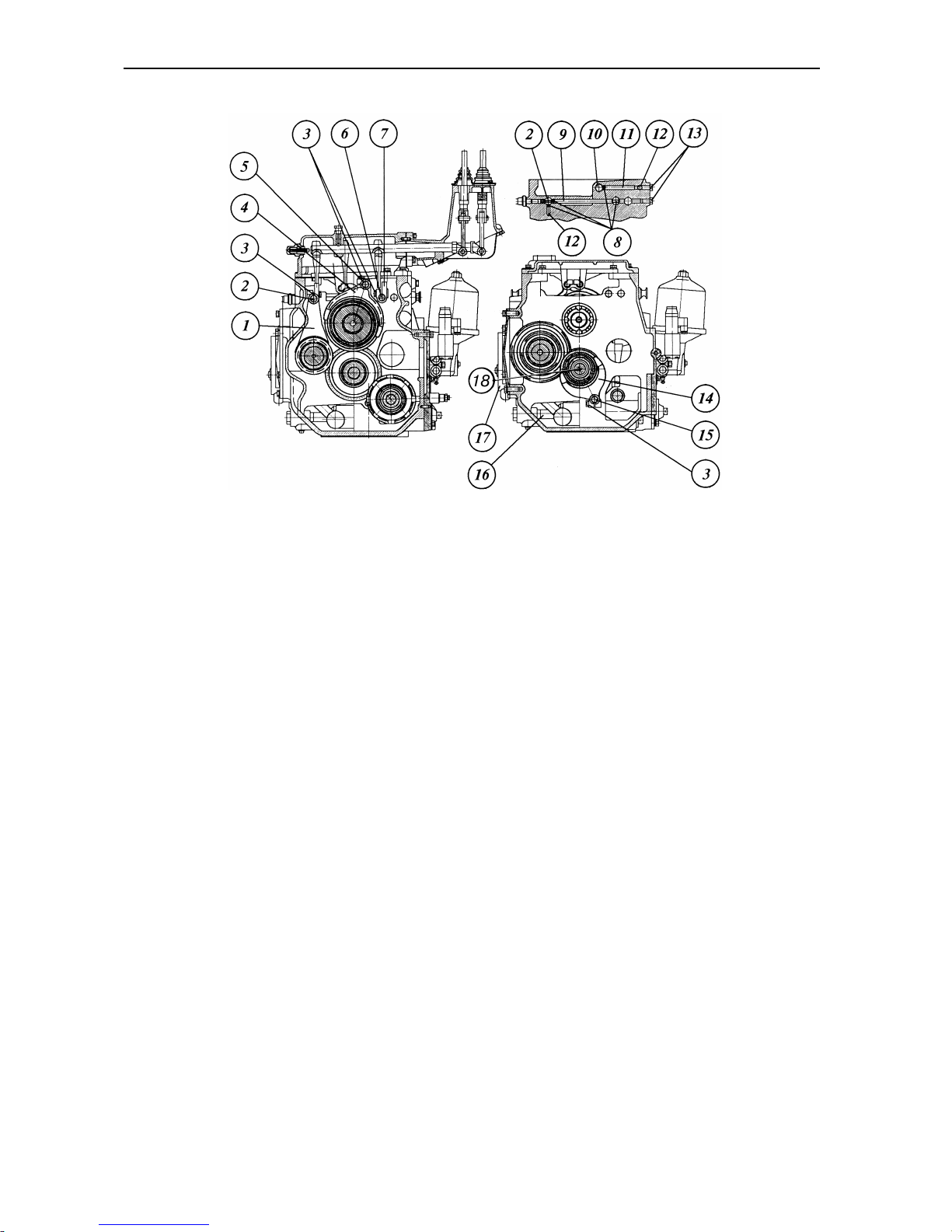
BELARUS-1221.2/1221В.2/1221.3 Description and operation
89
Fig. E-14. Gearbox:
1, 4, 14 – forks; 2, 5, 6, 10, 15 – dogs; 3, 13 – bolts; 7 – dog; 9 – pin; 11 – lock;
12 – spring; 8 – ball; 16 – filter; 17 – pump casing; 18 – inner shaft.
To exclude simultaneous engagement of
the two toothed couplings (26) (Fig. E-
12.1) and (3) (Fig. E-12.2) the locking
balls (8) (Fig. E-14) are installed in holes
in the GB casing (Fig. E-14).
Page 91
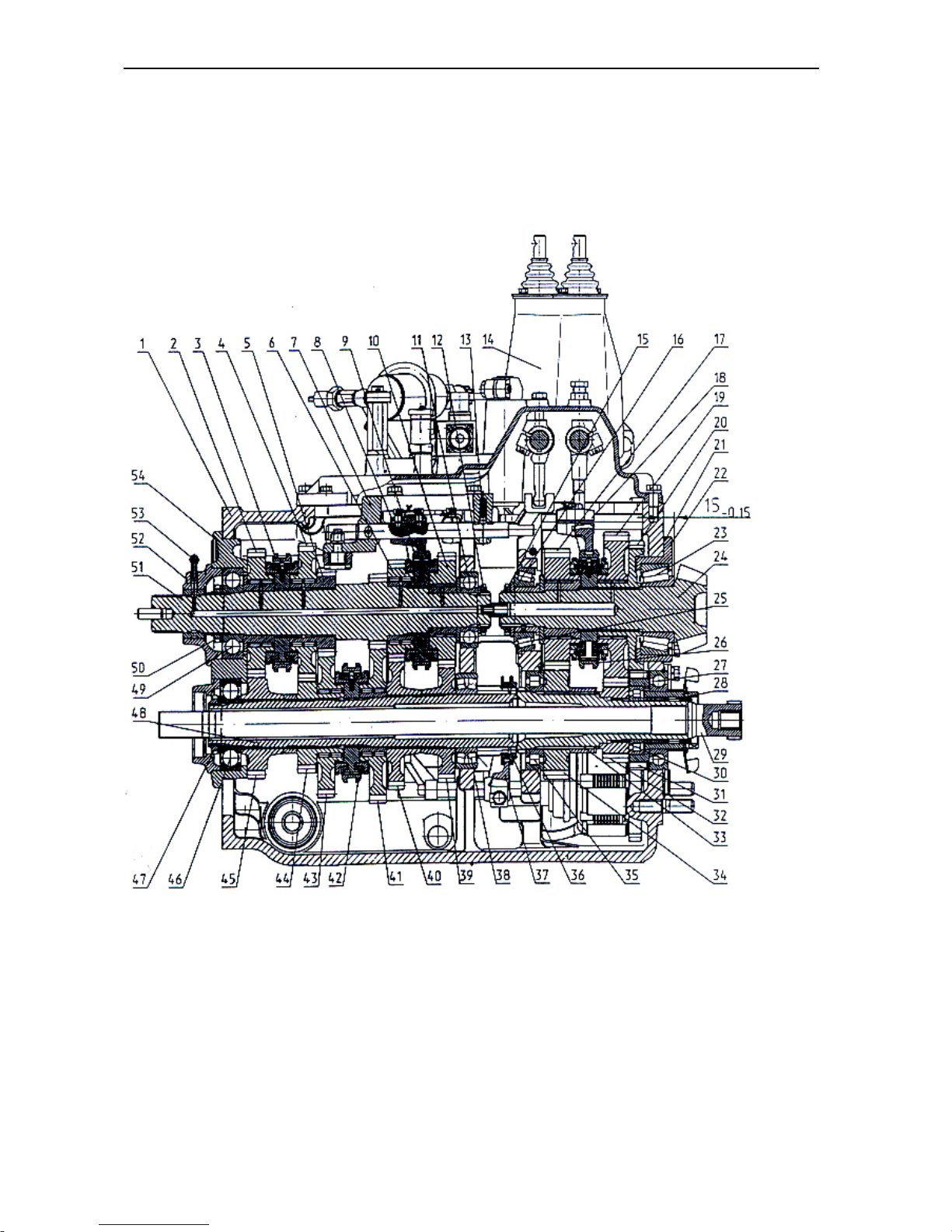
BELARUS-1221.2/1221В.2/1221.3 Description and operation
90
24F+12R gearbox (GB) (option)
The transmission gearbox (Fig. E-15.1) is a mechanical-type fixed-ratio unit with speed
ranges. It consists of a speed-gear assembly, downshift gear and reverse shaft, gear cluster, secondary shaft which are installed in the casing as well as the control mechanism and
hydraulic system units.
Fig. E-15.1. Transmission gearbox (longitudinal section):
1 – casing; 2, 4, 5, 6, 10, 17, 19, 20, 31, 32,34, 39, 40, 41, 43, 44, 45 – gears; 3, 9, 26, 42 – synchronizers; 7
– fork asembly; 8, 18, 37 – forks; 11, 23, 25, 27, 28, 30, 35, 38, 46, 49 – bearings; 12, 15, 47, 50 – nuts; 13 –
ball-point lock; 14 – control mechanism; 16, 21 – adjusting shims; 22 – bearing seat; 29 – continuous PTO
drive shaft; 33 – gear-cluster shaft; 36 – toothed coupling; 48 – intermediate shaft; 51 – primary shaft; 52 –
lubrication delivery cup; 53 – oil pipeline; 54 – cover.
Page 92
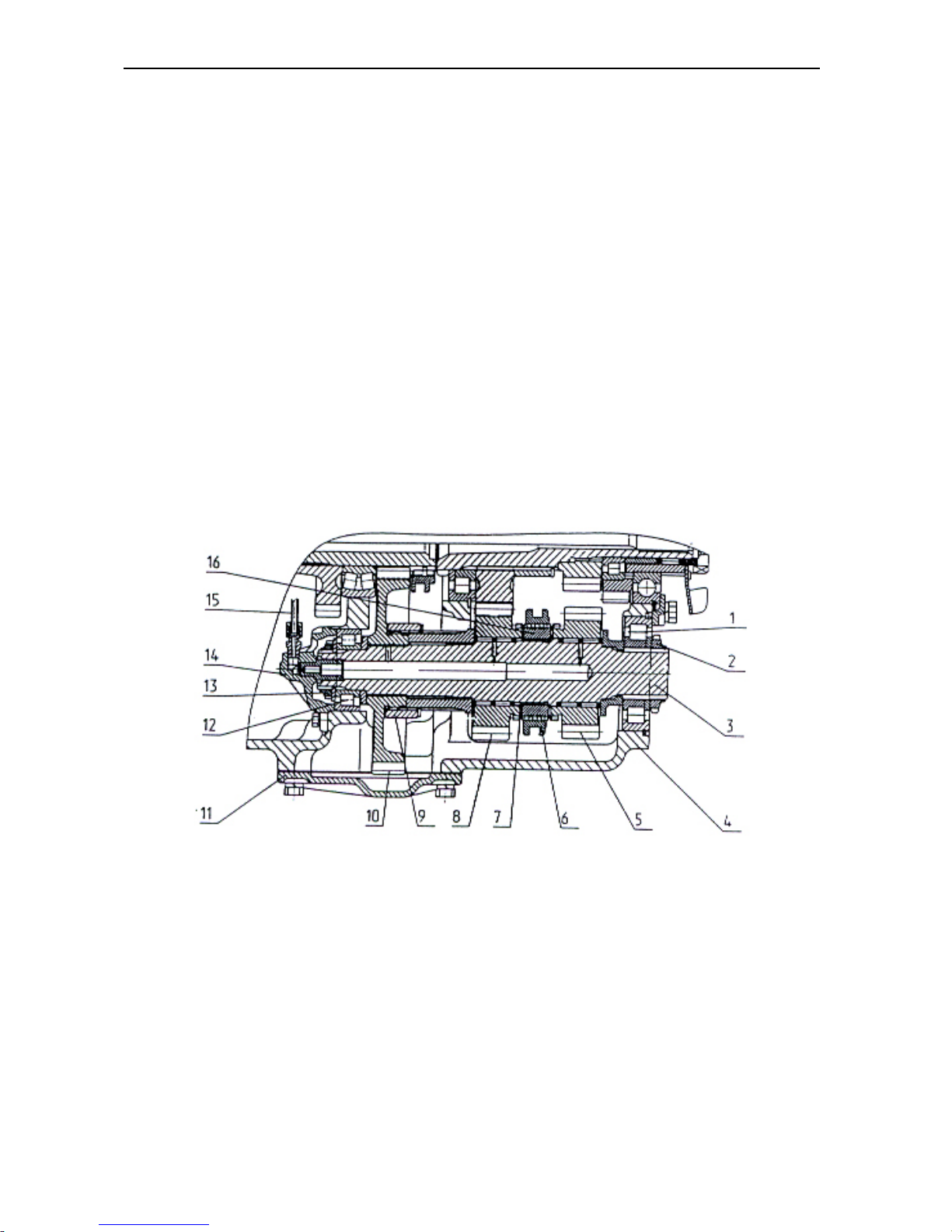
BELARUS-1221.2/1221В.2/1221.3 Description and operation
91
The speed-gear assembly is mounted
on the cover (54) and consists of the primary shaft (51) with driving pinions (2, 4,
6, 10) mounted in needle bearings riding
thereon. These pinions ensure engagement of the 5th, 6th, 3rd and 4th gear, respectively. The driving pinion of the 1st
gear is made integral with the shaft (51)
and the driving pinion of the 2nd gear is
fixed rigidly on the shaft. The needle
bearings are force-lubricated through the
oil pipeline (53) and holes drilled in the
shaft. The male splines of the shaft carry
two inertia-type synchronizers (4) and (9);
the latter effect engagement of the 5th, 6th,
3rd, and 4th gears. The primary shaft rests
on ball bearings mounted in the cover
(54) and casing (1).
The intermediate shaft (48) carries the
press-fitted driven pinions (54, 40 and 39)
of the 5th, 6th, 3rd and 4th gear, respectively. The driven pinions (43 and 41) of
2nd and 1st gears, respectively, rest on
needle bearings. An inertia-type synchronizer (42) to help engagement of the 1st
and 2nd gears.
The downshift and reverse gear shaft 3
(see Fig. E-15.2) is mounted in the body
(4) and rests on bearings (1 and 12). The
shaft also carries a driven pinion (10)
which is coupled to the shaft through
bushings (9), forward driving pinion (8)
and reverse pinion (5) running in needle
bearings. These pinions are coupled with
the shaft through a toothed coupling (6).
Bushing (16) which sits on male splines
of the shaft is locked on the shaft by
means of a retaining ring (7).
Fig. E-15.2 Downshift and reverse gear shaft:
1, 12 – bearings; 2, 13 – nuts; 4 –casing; 5, 8, 10 –pinions; 6 – toothed coupling; 7 – retaining ring; 9 – bush-
ing; 11 – cover; 14 – oil delivery cup; 15 – oil pipeline; 16 – bushing
Page 93
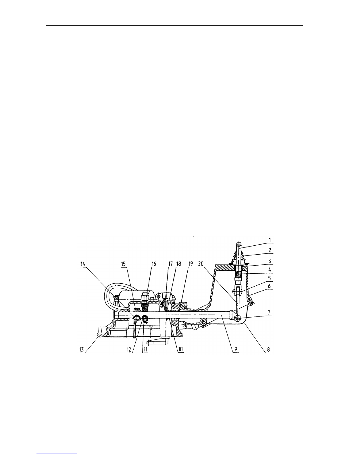
BELARUS-1221.2/1221В.2/1221.3 Description and operation
92
The gear-cluster shaft 33 (see Fig. E-
15.1) is installed in the casing (1) and
rests in bearings (27) and (35). Gears
(32) and (34) are splined-mounted on the
shaft and locked with retaining rings. The
PTO driven pinion (31) is mounted on the
shaft in roller bearings (28) and (30).
The secondary shaft 24 (see Fig. E-
15.1) is installed in the body (1) in tapered bearings (23) and (25). The bearings are adjusted by shims (16), while the
position of the shaft bevel pinion relative
to the body end-face (size 15
-0.15
) is adjusted through selection of the adjusting
shims (21). The FDA and synchronous
PTO drive pinion (20) and the synchronizer (26) boss are rigidly fixed on the
shaft. The driven pinions (17) and (19)
rest in needle bearings; the latter are
force-lubricated through the holes drilled
in the shaft. The shifting between the pinions is made with the locked-on-dog fork
(18) by means of the synchronizer (26).
The dog is installed in a recess in the
casing (1) and fixed with a ball-point lock.
The sets of components on the primary,
intermediate, secondary as well as downshift-and –reverse gear shafts are tightened up by nuts (12, 15, 47 and 50).
Transmission Gearbox Control
Mechanism
The transmission gearbox mechanism
comprises a gear-shift mechanism and a
speed-range change-over mechanism
with an electro-hydraulic system of
change-over between high “H” and lower
“L” stages of the GB reduction gear.
The gear-shift mechanism (Fig. E-15.3)
is mounted in the speed-gear assembly,
fork member (7) and the control mechanism (14) cover (see Fig. E-15.1).
The cover (54) (Fig. E-15.1) houses the
dogs with shifting forks of 1st, 2nd and 5th,
6th gears fastened thereto. The dogs are
fixed in the cover with ball-point locks.
The position of forks on the dogs is adjusted by means of tapered screws.
Fig. E-15.3. Gear-shift mechanism:
1 – fork; 2 – boot; 3 – sphere socket; 4 – spring; 5, 7 – pins; 6 – casing; 8 – cover; 9 – shaft; 11 – bolt; 12 –
bushing; 13 – cover; 14 – key; 15, 20 – levers; 16 – pick-up; 17 – screw; – 18 – washer; 19 – retaining ring.
Page 94
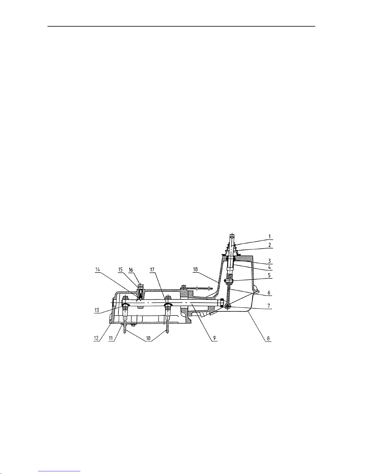
BELARUS-1221.2/1221В.2/1221.3 Description and operation
93
Three dogs, a fork (8), ball-point lock (13)
and parts of the two gear engagement
lockout mechanism are installed in the
fork assembly (7). The member is attached to the transmission gearbox casing (1).
The shaft (9) with the arm (15) and bushing (12) fitted thereon is installed in the
supports of cover (13) and casing (6) (see
Fig. E-15.3). The two bushings (18) and
spring (10) are installed between the retaining rings (19). The bushing end-faces
abut the screw (17) and the casing (6)
end-face. This arrangement serves to set
the gear-shift lever to neutral. The shaft
(9) is coupled with fork (1), with the gearshift lever fixed thereto through the pins
(5 and 7) and lever (20). The fork (1) is
located in the casing (6), in the sphere
socket (3) and spring-loaded with the
spring (4).
The speed range change-over mecha-
nism (Fig. E-15.4) is installed in the
transmission gearbox casing (1) and
cover of the gear-shift mechanism (14)
(see Fig. E-15.1).
In the casing (1), the fork (37) for changing-over the toothed coupling (36), the
fork for changing-over the toothed coupling (6) (see Fig. E-15.2) and the fork
(18) for changing-over the synchronizer
(26) (see Fig. E-15.1) are mounted on the
dogs. The dogs are locked in the body
with ball-point locks.
In the control mechanism (Fig. 15.4), the
shaft (9) together with arms (10) keyed
thereto rests in the supports of cover (12)
and housing (18). The shaft (9) is locked
with a ball-point lock (14) and is connected to fork (1) with attached speedrange change-over lever by means of
pins (5 and 7). The fork (1) is located in
the casing (18), in the sphere socket (3)
and preloaded with spring (4).
Fig. E-15.4. Speed-range change-over mechanism:
1 – fork; 2 – boot; 3 – sphere socket; 4 – spring; 5, 7 – pins; 6, 10 – levers; 8 – covers; 9 – shaft; 11 – link;
13, 17 – keys; 14 – ball-point lock; 15 – nut; 16 – bolt; 18 – casing.
Page 95
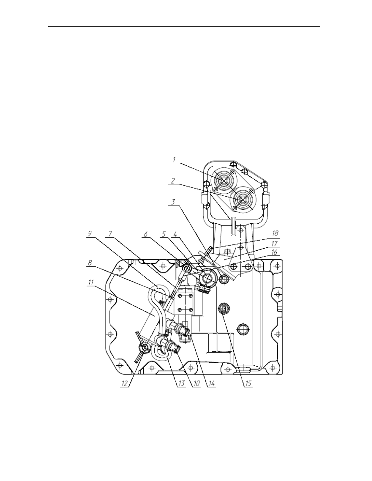
BELARUS-1221.2/1221В.2/1221.3 Description and operation
94
The high-to-low reduction gear stage
switch-over mechanism of the transmission gearbox (Fig. E-15.5) is
mounted on the gear-shift mechanism
cover and consists of a cylinder (11) fixed
on the axle (12), pusher (7) and lever (5)
mounted on the roller (4). The fork (16) is
connected with the lever (5) by means of
the pin (6). The lever of the roller (4)
meshes with the dog of the fork (18) (Fig.
E-15.1) and forces the synchronizer (26)
coupling to move as the roller rotates.
The position of lever (5) is adjusted by
changing the length of the pusher (7) with
further locking by a check-nut (8). The
cylinder (11) communicates with the hydraulic system through an electrohydraulic valve (14). The sensor (15)
connects the valve (14) to the electric circuit when the gear-shift lever is in its neutral position, only. The drawn-in position
of the cylinder corresponds to the lower
“L” stage of the transmission gearbox reduction gear. Pressure-sensitive pick-ups
(10) serve to indicate the engaged state
of the reduction gear.
Fig. E-15.5. High-to-low reduction gear stage switch-over mechanism:
1 – gear-shift fork; 2 – speed range change-over fork; 3 – bolt; 4 – roller; 5 – lever; 6 – pin; 7 – pusher; 8 –
check-nut; 9, 13 – oil pipelines; 10 – pressure-sensitive pick-up; 11 – hydraulic cylinder; 12 – axle; 14 – elec-
tro-hydraulic valve; 15 – sensor, 16 – fork, 17 – bracket, 18 – adjusting screw.
Page 96
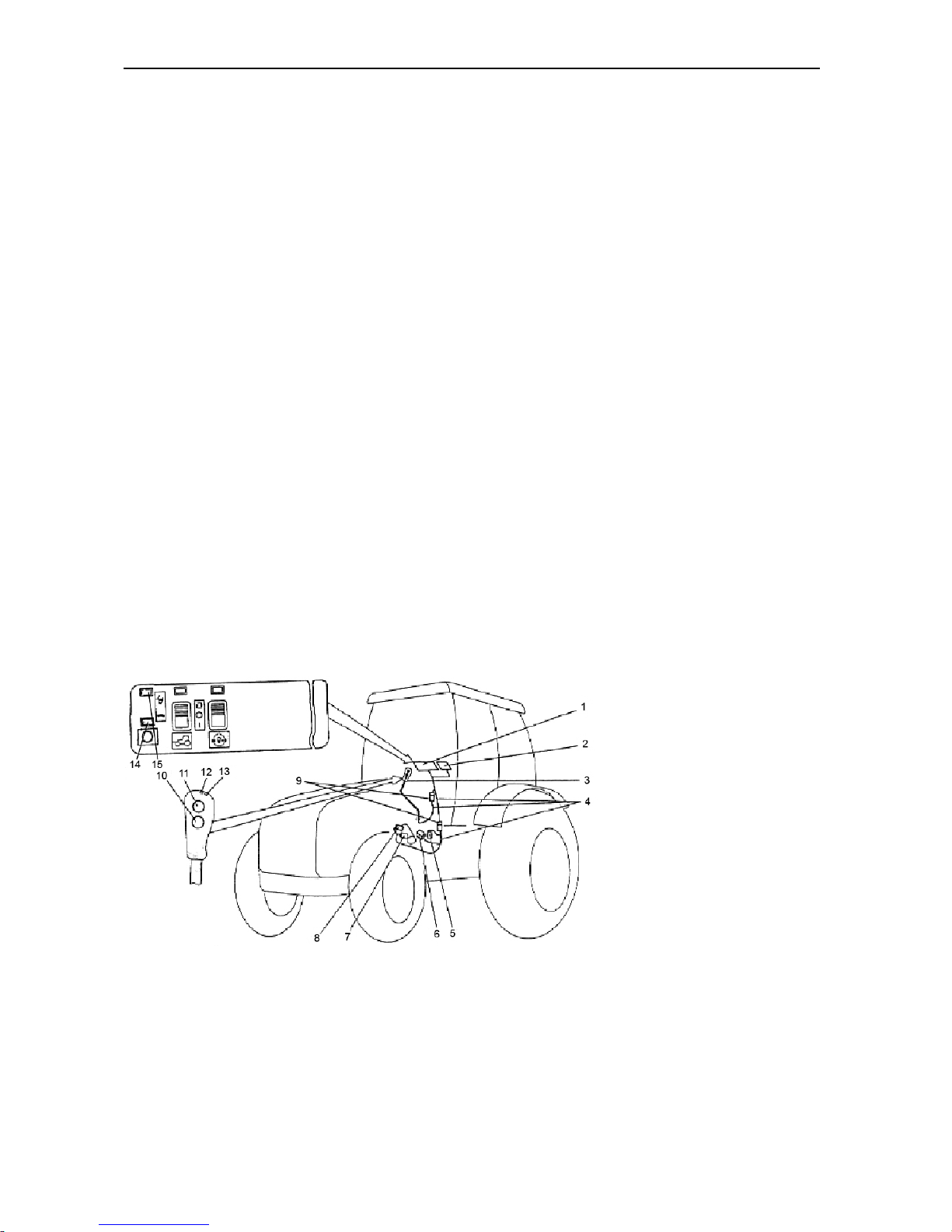
BELARUS-1221.2/1221В.2/1221.3 Description and operation
95
Transmission Gearbox Reduction Gear
Control System
The electro-hydraulic control system
(Fig. E-15.6) involves a control panel (1)
located in the tractor cab to the right of
the driver, a gear-shift and reduction gear
stage switch-over lever (3), GB neutral
pickup (5), sensors (7 and 8) mounted on
the reduction gear switch-over hydraulic
cylinder (11) (Fig. E-15.5), electrohydraulic distributor (6) located atop of
the transmission gearbox cover, and connecting cables (4) with terminal blocks
(9). The system is supplied with power
from the on-board power system through
a fuse block (2). Voltage is applied following the engine start-up.
The handle of the lever (3) contains the
pushbuttons (10 and 11) and indicators
(LEDs) (13, 12) to signal the high or low
reduction gear stage ON-state, respectively.
The panel (1) contains also the indicators
(15 and 14) to signal the ON-state of the
high or low reduction gear stage and reduction gear control relay.
The system allows the reduction gear
stages to be switched over when the
lever (3) is in its neural position only (contacts of the transmission gearbox neutral
position pickup (5) are closed).
Signals are applied to sensors (13, 12)
and (15, 14) from respective pressuresensitive pickups (8, 7).
Following the engine start-up, the default
setting is the reduction gear low stage
ON. In this case, the LED indicators (13,
15) should be on.
Switch over to the reduction gear high
stage is to be effected by depressing the
pushbutton (11). Now, the LED indicators
(13, 15) should go off, while LEDs (12,
14) turn on.
Switching over from high to low stage is
achieved be depressing the pushbutton
(10).
The control system circuit diagram for the
GB reduction gear, DL and FDA control is
given at the end of the “Manual”.
ATTENTION! The reduction gear stages shall be
only changed-over from the
lower stage to the higher
one and vice versa when
the tractor is fully stopped.
Fig. E-15.6
1 – control panel; 2 – fuse box; 3 – gear-shift and reduction gear stage switch-over lever; 4 – connecting cables; 5 – transmission gearbox neutral position pickup; 6 – reduction-gear electrical distributor; 7 – higher
stage pressure pickup; 8 – lower stage pressure pickup; 9 – terminal blocks; 10 – lower stage switch-on
pushbutton; 11 – higher stage switch-on pushbutton; 12 – higher stage LED indicator; 13 – lower stage LED
indicator; 14, 15 – pilot lamps.
Page 97
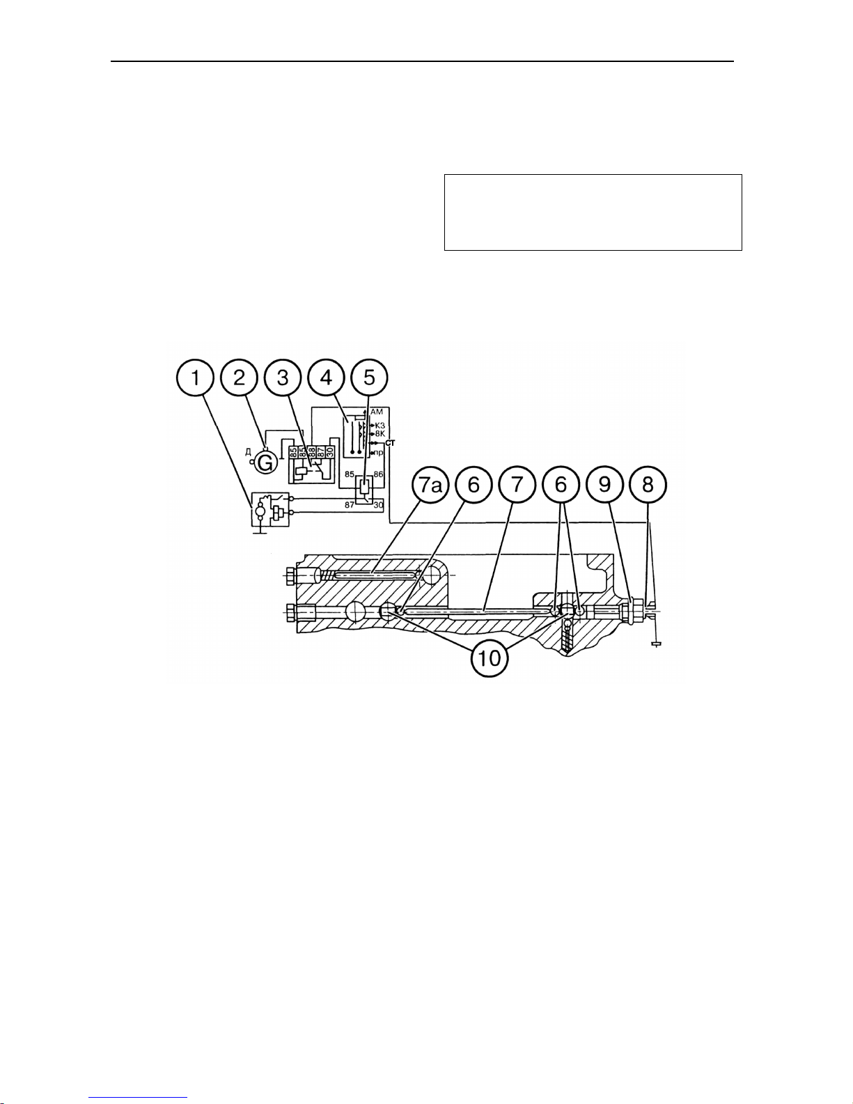
BELARUS-1221.2/1221В.2/1221.3 Description and operation
96
Engine Starting Interlock
As a precautionary measure against the
engine starting when the range is
switched on, the tractor is equipped with a
special interlock device (Fig. E-15.7). The
interlock consists of a switch (8) located in
the transmission gearbox casing on the
left side, balls (6) and pins (7, 7а).
On switching the range on, the interlock
mechanism opens the switch contacts and
breaks the circuit of the starter intermediate relay (1).
The shims (9) are provided to adjust the
instant of contact opening (9).
ATTENTION! Before proceeding to
starting the engine, set the transmission
gearbox speed-range change-over lever
to its neutral position!
Fig. E-15.7. Diagram of interlocking the engine starting:
1 – starter; 2 – alternator; 3 – interlock relay; 4 – starter switch; 5 – starter relay; 6 – interlock mechanism
balls; 7 – pin; 7a – lock; 8 – unlock switch; 9 – adjusting shims; 10 – range switch-over dogs
Page 98
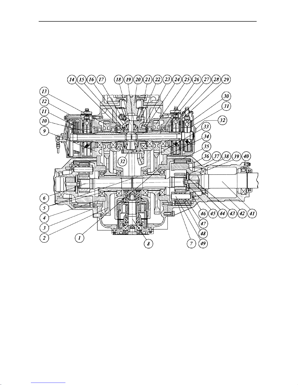
BELARUS-1221.2/1221В.2/1221.3 Description and operation
97
Rear Axle
The rear axle (Fig. E-16) consists of the
final drive, differential assembled with a
hydraulically-driven friction clutch used for
locking, hub drives located in the rear axle
housing, and the will transmission assemblies located in the half-axle housings.
Fig. E-16. Rear axle:
1, 4, 9, 27 – bearing bodies; 2 – hub-drive gear; 3 – left-hand half-axle housing; 5 – hub-drive gear bushings;
6 – torsion bar; 7 – differential pinion; 8 – PTO; 10 – left-hand hub-drive pinion shaft; 11 – differential lock
clutch; 12 – differential lock housing; 13 – hub-drive pinion; 14 – half-axle gear bearing washer; 15 – halfaxle gear; 16 – differential cover; 17 – differential pinion; 18 – differential spider; 19 – spherical washer; 20 –
final drive pinion; 21 – final drive gear; 22 – differential case; 23 – bearing; 24 – thrust ring; 25 – hub-drive
pinion; 26 – right-hand pinion shaft; 28 – service brake; 29 – service brake housing; 30 – parking brake; 31 –
parking brake housing; 32 – bolt; 33 – hub-drive gear; 34, 44 – adjusting shims; 35 – crown gear; 36 – crown
gear hub; 37 – cage; 38 – sun gear; 39, 40 – bearings; 41 – half-axle; 42 – right-hand half-axle; 43 – bolt; 45
– thrust washer; 46 – arresting plate; 47 – washer; 48 – rollers; 49 – differential pinion axle.
Page 99

BELARUS-1221.2/1221В.2/1221.3 Description and operation
98
Final Drive
The final drive of a bevel circular-arc teeth
type consists of a final-drive bevel pinion
(20), which is integral with the transmission gearbox secondary shaft, and a final
drive gear (21), the latter being bolted to
the differential case (22).
Differential
The differential of the closed lockable
bevel-pinion type consists of the case (22)
and cover (16) fastened together by
means of the bolts (32), four differential
pinions (17) together with spherical washers (19) and two thrust washers (14). The
differential case is installed as an assembly in the rear-axle housing in two roller
bearings (23). To lock the differential, the
hydraulically-controlled friction multipledisk clutch (Fig. E-17) which interlocks the
cross and the differential pinions with the
left-hand half-axle gear of the differential.
Hub Drives
The hub drives consist of two pairs of
straight spur pinions and gears (13, 2) and
(25, 33) (Fig. E-16).
The hub-drive pinions (13, 25) are
mounted in the splines of shafts (10, 26)
which are running in roller bearing bodies.
The differential is locked axially by means
of the bearings (23).
The shafts (10) and (26) link the half-axle
gears (15) with the hub-drive pinions and
the brake disks through their spline joints.
The hub-drive gears (2, 33) are mounted
on splined bushings (5) which are
mounted on ball bearings.
The adjusting shims (34) with the thickness of 0.2 mm and 0.5 mm are inserted
between the flanges of the bearing bodies
(9, 27) and the rear axle housing for adjustment of the axial clearance in the
bevel roller bearings (23) and backlask in
the final drive pinion-to-gear (20), (21)
pair. The bevel roller bearings shall be so
adjusted that the torque needed for turning the differential would be 5 to 8 N-m.
The backlash in the final drive shall be
within the range 0.20…0.55 mm.
Wheel Transmissions
The wheel transmissions are made up of
two straight-spur planetary trains, located
in the half-axle housings (3, 42), torsion
bars (6) made with splines which link the
hub-drive gears (2, 33) with the abovementioned planetary trains through
splined bushings (5).
The planetary train consists of a fixed
crown gear (35) mounted on the boss (36)
and bolted to the housing (42); carrier
(37); sun gear (38) seated on the splines
of torsion bar (6) and four differential pinions (50) running on the rollers (48) of the
axles (49).
The half-axle bearings (39, 40) are adjusted by formation of stocks of shims (44)
with the thickness of 0.2-mm and 0.5 mm.
Page 100
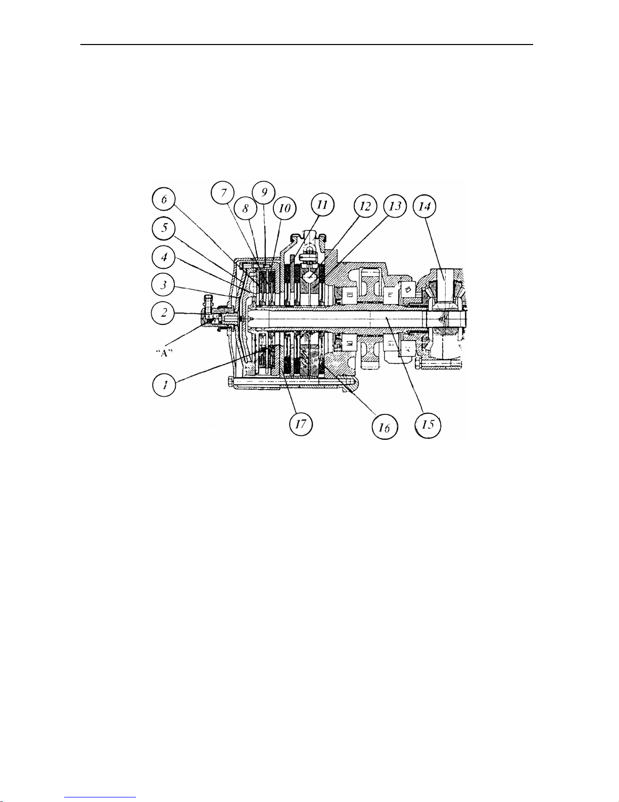
BELARUS-1221.2/1221В.2/1221.3 Description and operation
99
Differential Lock Clutch and Three-Disk Service Brake
The multiple-disk hydraulically controlled
differential lock clutch (1) (Fig. E-17) is located in casing (8) which is bolted to the
rear axle housing through the housing of
the left-hand three-disk brake and the
bearing body. The three-disk dry service
brake housing (17) contains the brake
disks (16), pressure disks (13), intermediate disk (11), balls (15) and brake release
springs (not shown).
Fig. E-17. Differential lock clutch:
1 – lock clutch; 2 – adapter; 3 – diaphragm cover; 4 – pressure disk; 5 – diaphragm; 6 – release disk; 7 –
intermediate disk; 8 – housing; 9 – clutch body; 10 – locking; 11 – brake intermediate disk; 12 – ball; 13 –
pressure disk; 14 – differential spider; 15 – lock-up shaft; 16 – brake disk; 17 – left-hand three-disk brake
housing.
The clutch consists of lock-up shaft (15)
which is spline-coupled with the differential spider (14), body (9), pressure disk (4),
release disk (6), diaphragm (5), cover (3),
adapter (2) and disks (10) spline-mounted
on the left-hand wheel transmission pinion.
Under the action of oil delivered under
pressure to the rod-end chamber “A” from
the ADL control hydraulic system, the diaphragm (5) in conjunction with the
pressure disk (4) moves and presses
disks (10) against the bearing surfaces of
the clutch body (9), intermediate disk (7)
and release disk (6) so that the differential
(the differential spider with the left-hand
half-axle gear) gets locked. When the front
wheels turn to a certain degree from the
straight-line motion, the rod-end chamber
“A” opens to the discharge line, and the
differential unlocks.
 Loading...