

Beko V30, T82 Service Bulletin

TV
TV
No. OF ISSUE : SB-BK0202
ISSUE DATE : 2002. 09. 06
« FILE THIS SERVICE BULLETIN WITH YOUR SERVICE MANUAL «
I/C : INTERCHANGEABILITY CODE
A
B
C
D
code
Interchangeable : Old and new parts can be used in products
as the bulletin regardless of manufacture date.
Old parts can be substituted for new parts : Old parts can be used in previous
products only. But new parts can be used regardless of manufacture date.
New parts can be substituted for old parts : Only new parts can be used
in products regardless of manufacture date.
Not interchangeable : New parts can be used in new products only.
N/C : NUMERAL CODE
1. To improve performance
2. To improve productivity
3. To improve reliability
4. Change of material or dimension
5. Addition
6. Deletion
7. Correction
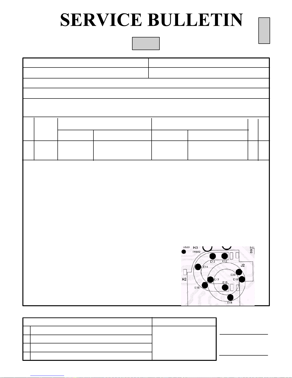
2. SYMPTOM/REASON :
The FBT is damaged due to arcing as shown in the attached picture. If the FBT is produced by
Termal, it must be changed with an Eldor FBT.
Note: The pin positions (on PCB) of Termal and Eldor brand FBT’s are different. Thus, 3 metal
eyelets should be removed and 5 eyelets should be added.
Please apply the following procedure to replace Termal FBT with Eldor FBT:
- Desolder the pins of Termal FBT and remove it.
- Remove the metal eyelets in position E17, E19 and E20 by cutting heads on the
component side of PCB (It is not necessary to remove E18)
Not: It is needed to prevent a possible arcing from ferrite of Eldor FBT to the eyelets of old FBT.
- Place metal eyelets (part code : 013114 ) to positions E12, E13, E14, E15 and E16.
- Fasten eyelets by applying pressure to the solder side with a (+) type screwdriver and turn it.
- Solder new Eldor FBT on the positions E12, E13, ... (see the component-side layout below).
1. GENERAL INFORMATION
? Application Model :
BUYER NAME : LG
BEKO MODEL : V30, T82
APPLICABLE SERIAL NO. : Immediately
SUBJECT : Damage of FBT due to Arcing (Replacing Termal brand FBT with Eldor FBT)
BUYER(LGE) MODEL : 28CZ10RX, 32CZ10RX
DATE OF CHANGE : 2002.08.24
l Issued by BEKO Engineering & Customer Service Division
Cengiz ARAT
CHIEF ENGINEER, R&D
Sükrü AKTAS
MANAGER, QA
NO
LOCA
NO.
BEFORE CHANGE AFTER CHANGE
PART NO. DESC. / SPEC. PART NO. DESC. / SPEC.
I
/
C
N/C
BEKO
1 TR502 058834-TR5 28” 16:9 FBT (Termal) 057834-EL2 28” 16:9 FBT (Eldor) C 3
1 TR502 058234-TR5 32” 16:9 FBT (Termal) 057234-EL3 32” 16:9 FBT (Eldor) C 3
« R529 119110 RMF 1R J 1W 119155 RMF 1.5R J 1W C 3
« If CPT brand is 28” Video Color (W66EJU023X015), then
Heater resistor R529 has to be replaced from 1R to 1.5R to
decrease the Heater voltage (for other CPT brands and
screen sizes, the R529 should not be replaced).
?? The part number of FBT is actually 058838(28”) and
058238(32”) in SPPL. So, if you order with those
part number, Beko will deliver Eldor FBT automatically.

CONTENTS PAGE
Safety Instructions 3
Technical Specifications 4
Pin Voltages of IC’s 5
Pin Voltages of Some Transistors 8
Oscillograms 9
Electrical and Service Adjustments 12
Trouble Shooting Guide 16
Parts List 23
Circuit Diagram PIP Module 30
Circuit Diagrams Attached
27/05/2002, Version 2
SAFETY INSTRUCTIONS
GENERAL GUIDELINES
1. It is advised to insert an isolation transformer
in the AC supply before servicing a hot
chassis.
2. Potentials as high as 33KV are present when
this receiver is in operation. Operation of the
receiver without the rear cover involves the
danger of a shock hazard from t he receiver
power supply. Servicing should not be
attempted by any one who is not
competent with the precautions necessary
when working on the high voltage
equipment. Always discharge the anode of
the tube.
3. When servicing observe the original lead
dress in the high voltage circuits. If a short
circuit is found, replace all the parts which
have been overheated or damaged by the
short circuit.
4. Always use the manufacturer’s replacement
safety components. The critical safety
components marked with
on the
schematics diagrams should not be
replaced by other substitutes. Other
substitute may create the electrical shock,
fire or other hazards. Take attention to
replace the spacers with the originals.
Furthermore where a short circuit has
occurred, replace those components that
indicate evidence of overheating.
5. After servicing, see that all the protective
devices such as insulation barriers, insulation
papers, shields and isolation R-C
combinations are correctly installed.
6. When the receiver is not being used for a
long time of period of time, unplug the
power cord from the AC outlet.
7. After servicing make the following leakage
current checks to prevent the customer
from being exposed to shock hazard.
LEAKAGE CURRENT COLD CHECK
1. Unplug the AC cord and connect a jumper
between the two prongs of the plug.
2. Turn the receiver’s power switch on.
3. Measure the resistance value with an
ohmmeter, between the jumpered AC plug
and each exposed metallic cabinet part on
the receiver, such as screw heads, aerials,
connectors, control shafts etc. When the
exposed metallic part a return path to the
chassis the reading should be between
4Mohm and the 20Mohm. When the
exposed metal does not have a return path
to the chassis, the reading must be infinite.
LEAKAGE CURRENT HOT CHECK
1. Plug the AC cord directly in to the AC
outlet. Do not use an isolation transformer
for this check.
2. Connect a 2Kohm 10W resistor in series with
an exposed metallic part on the receiver
and an earth, such as a water pipe.
3. Use an AC voltmeter with high impedance
to measure the potential across the resistor.
4. Check each exposed metallic part and
check the voltage at the each point.
5. Reverse the AC plug at the outlet and
repeat each of the above measurements.
6. The potential at the any point should not
exceed 1.4 Vrms. In case a measurement is
outside the limits specified, there is the
possibility of a shock hazard, and the
receiver should be repaired and rechecked
before it is returned to the customer.
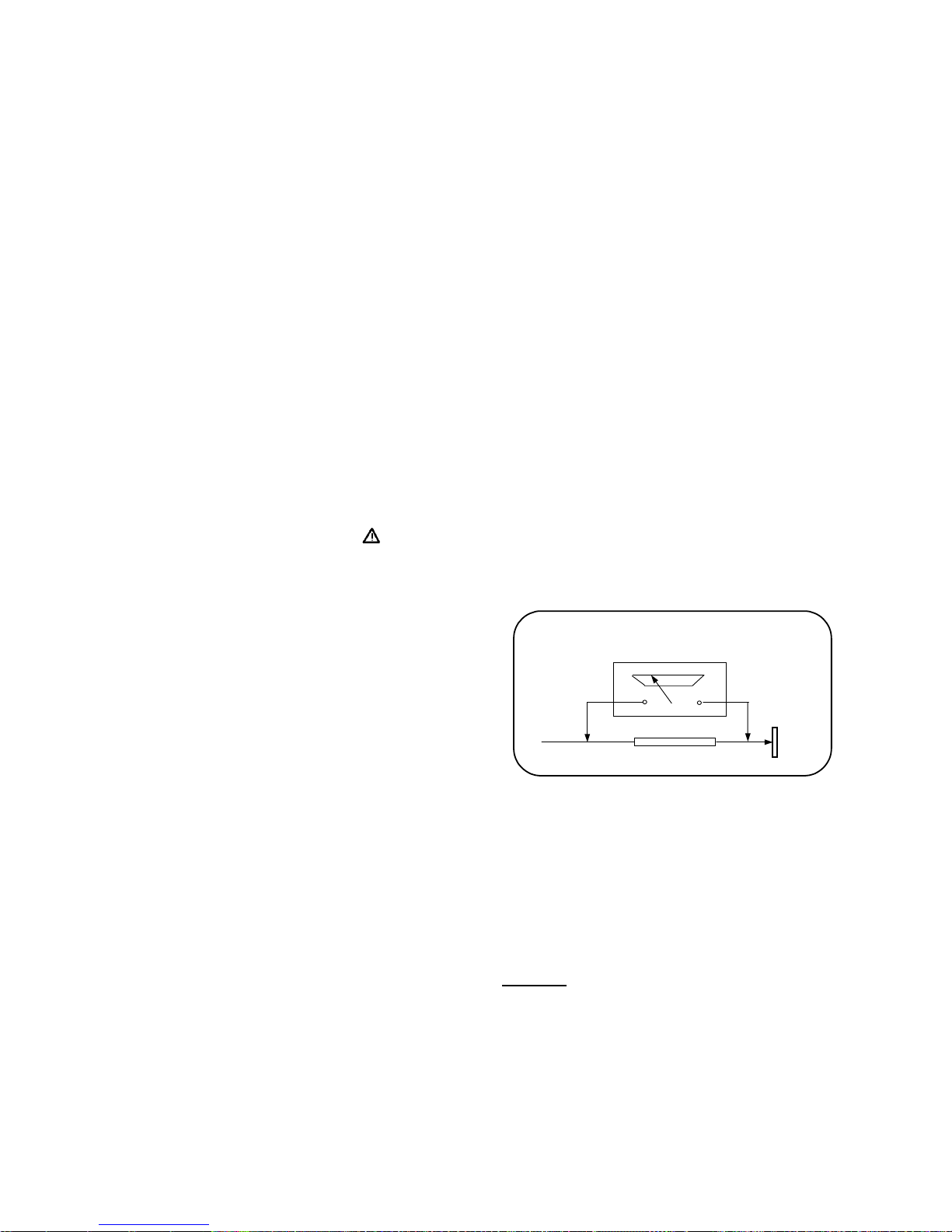
HOT CHECK CIRCUIT
AC-Voltmeter
TO INSTRUMENTS
EXPOSED
METALLIC PARTS
Water pipe
(earth)
2 K Ohm
Figure 1
X-RAY RADIATION WARNING
The primary source of X-ray radiation in this receiver
is the picture tube. The chassis is specially
constructed to limit X-ray radiation. For continued
X-ray radiation protection, replace the tube with
the same type of the original one.
CAUTION
AFTER REMOVAL OF THE ANODE CAP, DISCHARGE
THE ANODE OF THE PICTURE TUBE AND THE ANODE
CAP TO THE METAL CHASSIS, CRT SHIELD, OR THE
CARBON PAINTED ON THE CRT WITH A HIGH
VOLTAGE PROBE AND MULTIMETER (SELECT VDC)
AND THEN SHORT CIRCUIT DIRECTLY TO DISCHARGE
COMPLETELY.

TECHNICAL SPECIFICATIONS
Power source: 220-240 VAC, 50-60Hz
Power consumption (max.)
1
: 120 W 21” Pure Flat
125 W 25”, 28” Mono
145 W 25”, 28” 4/3, 29” Pure Flat
140 W 29” Super Flat
150 W 28” 16/9 Super Flat
155 W 28” 16/9 Pure Flat, 32” Super Flat
165 W 32” Pure Flat
160 W 33”
Standby power consumption : 3 W
Aerial impedance : 75Ohm, coaxial type
Receiving system
2
: PAL BG
PAL SECAM BG
PAL SECAM BG DK
PAL SECAM BG LL’
PAL I
Receiving channels: VHF BAND I , CH2-4
VHF BAND III , CH5-12
CABLE TV S1-41
UHF BAND CH21-69
NTSC Playback Frequencies: 3.58&4.43 MHz
Audio outputs : Stereo : 2 x 10W RMS at %10 THD (Except 21” Pure Flat)
2 x 7W RMS at %10 THD (21” Pure Flat)
+ 20W RMS at %10 THD (if subwoofer available)
Mono : 2 x 7W RMS at %10 THD
High Voltage : 28.5 ± 0.5 KV 25”, 28”4/3
29.0 ± 0.5 KV 28”16/9, 29”, 32” Super Flat
29.5 ± 0.5 KV 32” Pure Flat, 33”
Focus voltage : %25.6 ± %38 of EHT
Grid 2 voltage : 0-1400 V
Heater voltage : 6.2 ± 0.2 Vrms
Video/Audio Terminals : AV1/2 IN Video : 1 Vpp,75 Ohm
Audio : 0.5 Vrms, >10 Kohm
AV1 IN RGB
AV1/2 OUT Video : 1 Vpp, 75 Ohm
Audio : 0.5 Vrms, <1 Kohm
AV2 IN (RCA) Video : 1 Vpp, 75 Ohm
Audio : 0.5 Vrms, >10 Kohm
Operating temperature : 0-45 Degrees
Safety : IEC 65 /BS P2N
X-Ray radiation : ACC. IEC 65/BS P2N
1
: 20W should be added to find the max. power consumption of the models with subwoofer.
2
: TV set is produced to receive “one” of these colour and sound systems.
12
Pin Connection V DC Pin Connection V DC
1
Not connected
33
Scart 2 sound output (R) 3.7
2
Gnd 0
34
Scart 2 sound output (L) 3.7
3
Gnd 0
35
Reference analog ground 0
4
Digital control input/output 0
36
Scart 1 sound output (R) 3.7
5
Digital control input/output 0
37
Scart 1 sound output (L) 3.7
6
Gnd 0
38
Volume capacitor Headphone
7
Standby (in normal operation it must be high) 4.9
39
Analog Supply High Voltage (8V) 8
8
Not connected 4.9
40
Volume capacitor Speaker
9
SCL 2.4-2.6
41
Ground for Analog Power Supply High
0
10
SDA 1.8-2.1
42
Internal Analog Reference Voltage 3.7
11
Not connected 2.4
43
Scart 4 input (L) 3.7
12
Not connected 2.4
44
Scart 4 input (R) 3.7
13
Not connected 2.4
45
Analog Shield Ground 0
14
Not connected 4.9
46
CINCH - sound input (L) 3.7
15
Not connected 0.7
47
CINCH - sound input (R) 3.7
16
Not connected 0.7
48
Analog Shield Ground 0
17
ADR Bus Clock Output 0.7
49
Scart 2 sound input (L) 3.7
18
Digital Circuitry Supply Voltage 4.9
50
Scart 2 sound input (R) 3.7
19
Digital Circuitry Supply Ground 0
51
Analog Shield Ground 0
20
Not connected 0.7
52
Scart sound 1 input (R) 3.7
21
Not connected (Ground) 0
53
Scart 1 sound input (L) 3.7
22
Not connected (Ground) 0
54
A/D converter ref. Voltage 2.5
23
Not connected (Ground) 0
55
Mono sound input 3.7
24
MSP RESET input 4.9
56
Ground for Analog Power Supply Voltage 0
25
Headphone sound output (R) 2.1
57
Analog Power Supply Voltage (5V) 4.9
26
Headphone sound output (L) 2.1
58
IF input 1 1.5
27
Reference analog ground 0
59
IF Common reference for IF IN1/IN2 1.5
28
Speaker output (R) 0.1-2.1
60
IF input 2 0
29
Speaker output (L) 0.1-2.1
61
Factory test mode enable (ground) 0
30
Not connected 0.1-2.1
62
Crystal oss. input 2.3
31
Not connected 0.1-2.1
63
Crystal oss. output 2.3
32
Not connected 0
64
Not connected (Ground) 0
Pin Connection V DC Pin Connection V DC
1
Left In 1.6
7
0,5-0,9
2
Left In V 1.6
8
Right out 14.2
3
Mute 15.3
9
VS 28
4
Right In V 1.6
10
Left out 13.9
5
Right In 1.6
11
0,5-0,9
6
Gnd 0
12
Left In 0.6
Pin Connection V DC Pin Connection V DC
1
Input A 0,98 (0)
6
Vertical Flyback Supply Voltage 45,6 (10,9)
2
Input B 0.94 (0)
7
Output A 7,64 (0,1)
3
Supply voltage 14,7 (1.0)
8
Guard Output 0,3 (0)
4
Output B 7,55 (0,4)
9
Feedback Input 7,9 (0)
5
Gnd 0 (0)
Pin Connection V DC Pin Connection V DC
1
Demag 0.85 (0.0)
5
Driver 2.1 (0.14)
2
I sense 0.1 (0.32)
6
VCC 12.3 (8.8)
3
Control input 5 (5.5)
7
Not connected -
4
Gnd 0
8
VI 116 (117)
(*)
Standby values are given in parenthesis
IC303, IC304 (TDA7263) Audio Output IC
IC 301 (MSP 3400G) MULTI STANDARD SOUND PROCESSOR
IC601 (MC44608 AP) Power Supply IC
IC501 (TDA835X) Vertical Deflection Output IC
14
1. PH601 (PC127FY) PHOTOCOUPLER 2. T603 (BC848) NPN
Pin
Standby VDC
TV ON VDC
1 B C E B C E
2
T603
0.6 0.02 0 0.1 0.3 0
3
4
3. T604 (BC848) NPN 4. T605 (BC848) NPN
Standby VDC TV ON VDC Standby VDC TV ON VDC
B C E B C E B C E B C E
T604
0.02 12.7 0 0.7 0.05 0
T605
0.6 0.02 0 0.1 0.7 0
5. T606 (BC848) NPN 6. T607 (BC848) NPN
Standby VDC TV ON VDC Standby VDC TV ON VDC
B C E B C E B C E B C E
T606
0.6 0 0 1 6.8 0
T607
0.6 0 0 0.1 2.5 0
7. T307 (BC848) NPN
Standby VDC
TV ON VDC
B C E B C E
T307
0.6 0 0 0.1 15 0
PIN VOLTAGES OF SOME TRANSISTORS
10
5
12.3
ON VDC
11
Standby VDC
12.5
11.5
5.5
8.8
Note:
TV is connected to a patern generator (Colour bar, sound 1 kHz).
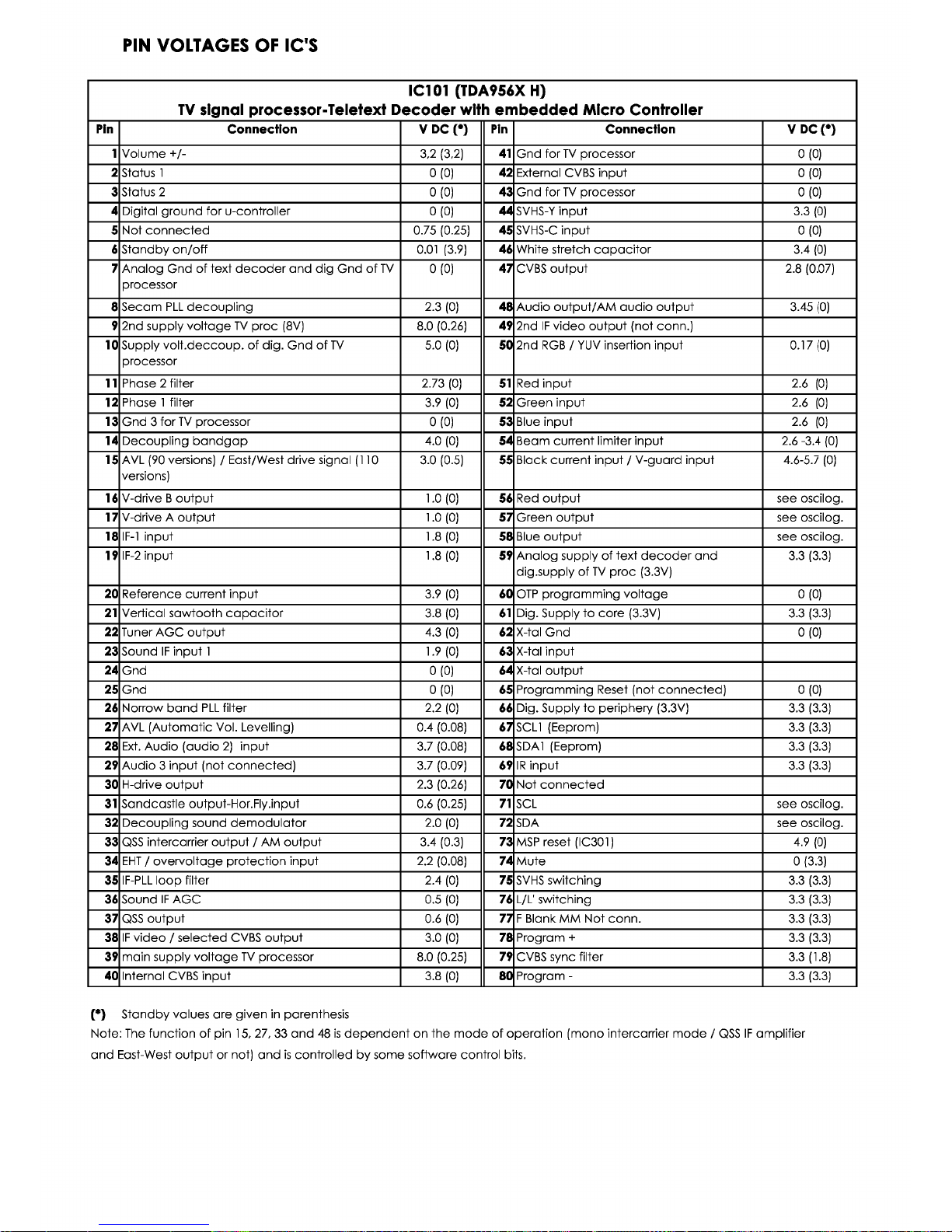
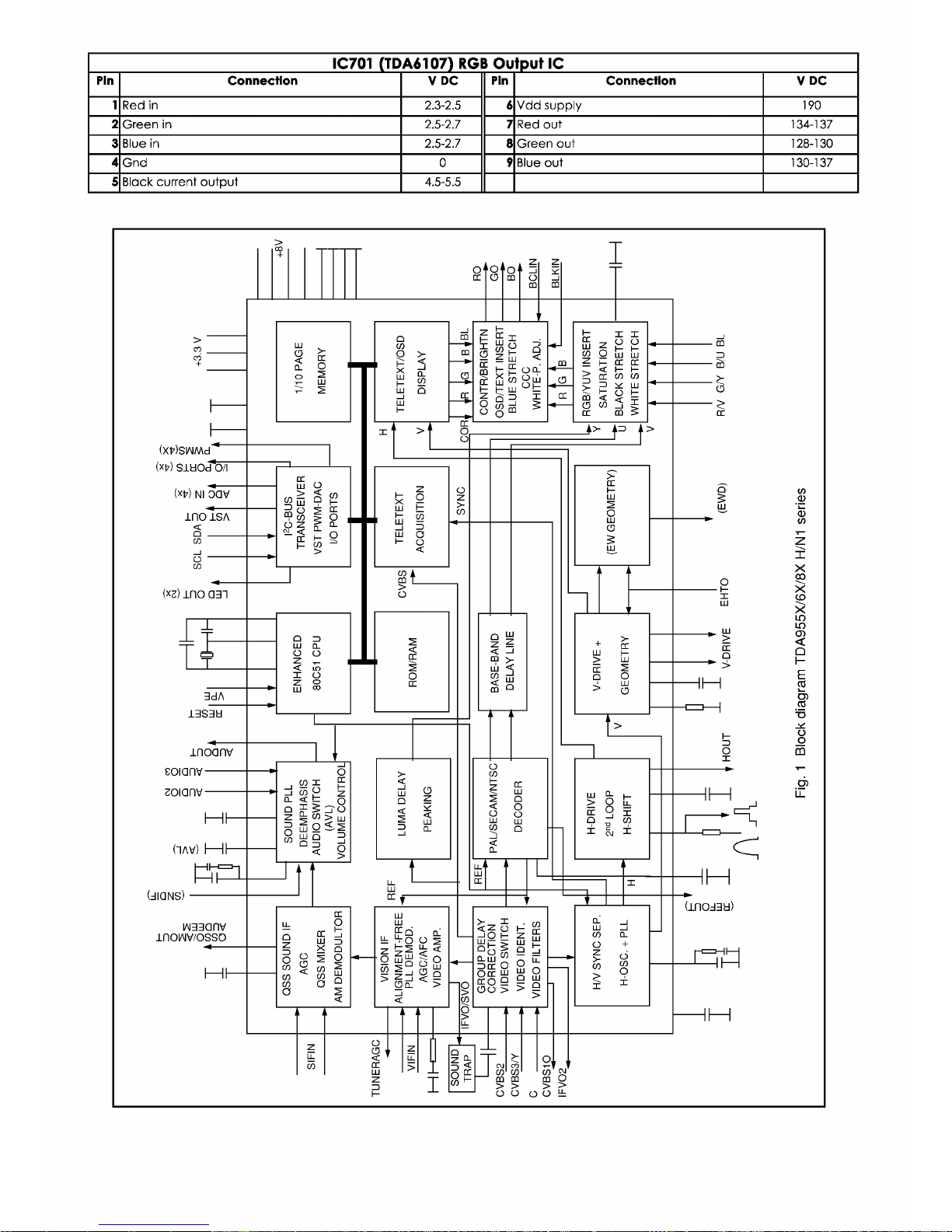
1. IC101 (TDA956X)
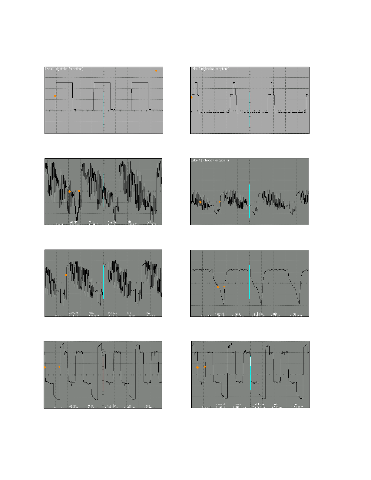
OSCILLOSGRAPHS OF SOME IC PINS
Pin 30
2V/div, 20 usn/div, Vpp=4.9 V, 15625 kHz
Pin 31
2V/div, 20 usn/div, Vpp=5.6 V, 15625 kHz
Pin 38
2V/div, 20 usn/div, Vpp=2.9 V, 15625 kHz
Pin 40
500 mV/div, 20 usn/div, Vpp=1.2 V, 15625 kHz
500 mV/div, 20 usn/div, Vpp=2.1 V, 15625 kHz
Pin 55
Pin 56 Pin 57
Pin 47
500 mV/div, 20 usn/div, Vpp=2.7 V, 15625 kHz
500 mV/div, 20 usn/div, Vpp=2.6 V, 15625 kHz
 Loading...