

Page 1

Service Manual
K5 CHASSIS-DVD COMBO TV
Page 2

CONTENTS PAGE
o Safety Instructions 2
o Technical Specifications 3
o Remote Control 4
o Preparations 7
o Operating Your TV 8
o Block Diagram 21
o IC Datasheets&Specs 22
o Pin Voltages of IC’s 29
o Oscillosgraphs Of Some IC Pins 31
o Electrical Adjustments 35
o Channel Frequency Tables 38
o Spare Part List 41
1
Page 3
1. SAFETY INSTRUCTIONS .
GENERAL GUIDELINES
1. It is advised to insert an isolation transformer
in the AC supply before servicing a hot
chassis.
2. Potentials as high as 33KV are present when
this receiver is in operation. Operation of the
receiver without the rear cover involves the
danger of a shock hazard from the receiver
power supply. Servicing should not be
attempted by any one who is not competent
with the precautions necessary when working
on the high voltage equipment. Always
discharge the anode of the tube.
3. When servicing observe the original lead
dress in the high voltage circuits. If a short
circuit is found, replace all the parts which
have been overheated or damaged by the
short circuit.
4. Always use the manufacturer’s replacement
safety components. The critical safety
components marked with
on the
schematics diagrams should not be replaced
by other substitutes. Other substitute may
create the electrical shock, fire or other
exposed metallic part a return path to the
chassis the reading should be between
4Mohm and the 20Mohm. When the exposed
metal does not have a return path to the
chassis, the reading must be infinite.
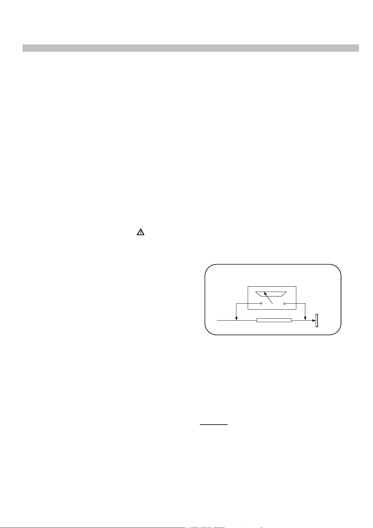
LEAKAGE CURRENT HOT CHECK
1. Plug the AC cord directly in to the AC outlet.
Do not use an isolation transformer for this
check.
2. Connect a 2Kohm 10W resistor in series with
an exposed metallic part on the receiver and
an earth, such as a water pipe.
3. Use an AC voltmeter with high impedance to
measure the potential across the resistor.
4. Check each exposed metallic part and
check the voltage at the each point.
5. Reverse the AC plug at the outlet and repeat
each of the above measurements.
6. The potential at the any point should not
exceed 1.4 Vrms. In case a measurement is
outside the limits specified, there is the
possibility of a shock hazard, and the receiver
should be repaired and rechecked before it
is returned to the customer.
hazards. Take attention to replace the
spacers with the originals. Furthermore where
a short circuit has occurred, replace those
components that indicate evidence of
overheating.
5. After servicing, see that all the protective
HOT CHECK CIRCUIT
TO INSTRUMENTS
EXPOSED
METALLIC PARTS
AC-Voltmeter
Water pipe
(earth)
devices such as insulation barriers, insulation
papers, shields and isolation R-C
2 K Ohm
combinations are correctly installed.
6. When the receiver is not being used for a
long time of period of time, unplug the
power cord from the AC outlet.
7. After servicing make the following leakage
current checks to prevent the customer from
being exposed to shock hazard.
LEAKAGE CURRENT COLD CHECK
1. Unplug the AC cord and connect a jumper
between the two prongs of the plug.
2. Turn the receiver’s power switch on.
3. Measure the resistance value with an
ohmmeter, between the jumpered AC plug
and each exposed metallic cabinet part on
the receiver, such as screw heads, aerials,
Figure 1
X-RAY RADIATION WARNING
The primary source of X-ray radiation in this receiver
is the picture tube. The chassis is specially
constructed to limit X-ray radiation. For continued Xray radiation protection, replace the tube with the
same type of the original one.
CAUTION
AFTER REMOVAL OF THE ANODE CAP, DISCHARGE THE
ANODE OF THE PICTURE TUBE AND THE ANODE CAP TO
THE METAL CHASSIS, CRT SHIELD, OR THE CARBON
PAINTED ON THE CRT WITH A HIGH VOLTAGE PROBE
AND MULTIMETER (SELECT VDC) AND THEN SHORT
CIRCUIT DIRECTLY TO DISCHARGE COMPLETELY
connectors, control shafts etc. When the
2
Page 4

2. TECHNICAL SPECIFICATIONS .
Power source: 220-240V AC, 50-60Hz
Power consumption (nom.) : 73W 20”, 21”
Standby power consumption : 2 W
Aerial impedance : 75Ohm, coaxial type
1
Receiving system
: PAL BG
PAL SECAM BG
PAL SECAM BG DK
PAL I
Receiving channels: VHF BAND I CH2-4
VHF BAND III CH5-12
CABLE TV S1-41
UHF BAND CH21-69
Audio outputs : 7W RMS at %10 THD 21”
High Voltage : 25 ± 0.5 KV 21”
Focus voltage : %25.6 ± %38 of EHT
Grid 2 voltage : 0-1400 V
Heater voltage : 6.2 ± 0.2 Vrms
Video/Audio Terminals : AV1 IN Video : 1 Vpp,75 Ohm
Audio : 0.5 Vrms, >10 Kohm
RGB
AV1OUT Video : 1 Vpp, 75 Ohm
Audio : 0.5 Vrms, <1 Kohm
AV2 IN Video : 1 Vpp,75 Ohm
Audio : 0.5 Vrms, >10 Kohm
RGB
AV2OUT Video : 1 Vpp, 75 Ohm
Audio : 0.5 Vrms, <1 Kohm
AV3 IN (RCA, optional) Video : 1 Vpp, 75 Ohm
Audio : 0.5 Vrms, >10 Kohm
Ambient temperature : 5ºC-40 ºC Degrees
Safety : IEC 65 /BS P2N
X-Ray radiation : ACC. IEC 65/BS P2N
Disc formats: DVD R, DVD RW, CD-R, CD-RW
Media formats: DVD video, audio CD, video CD
(VCD 1.0/1.1/2.0), S-Video CD,
CD-ROM (MP3, JPEG)
1
: TV set is produced to receive “one” of these colour and sound systems.
3
Page 5
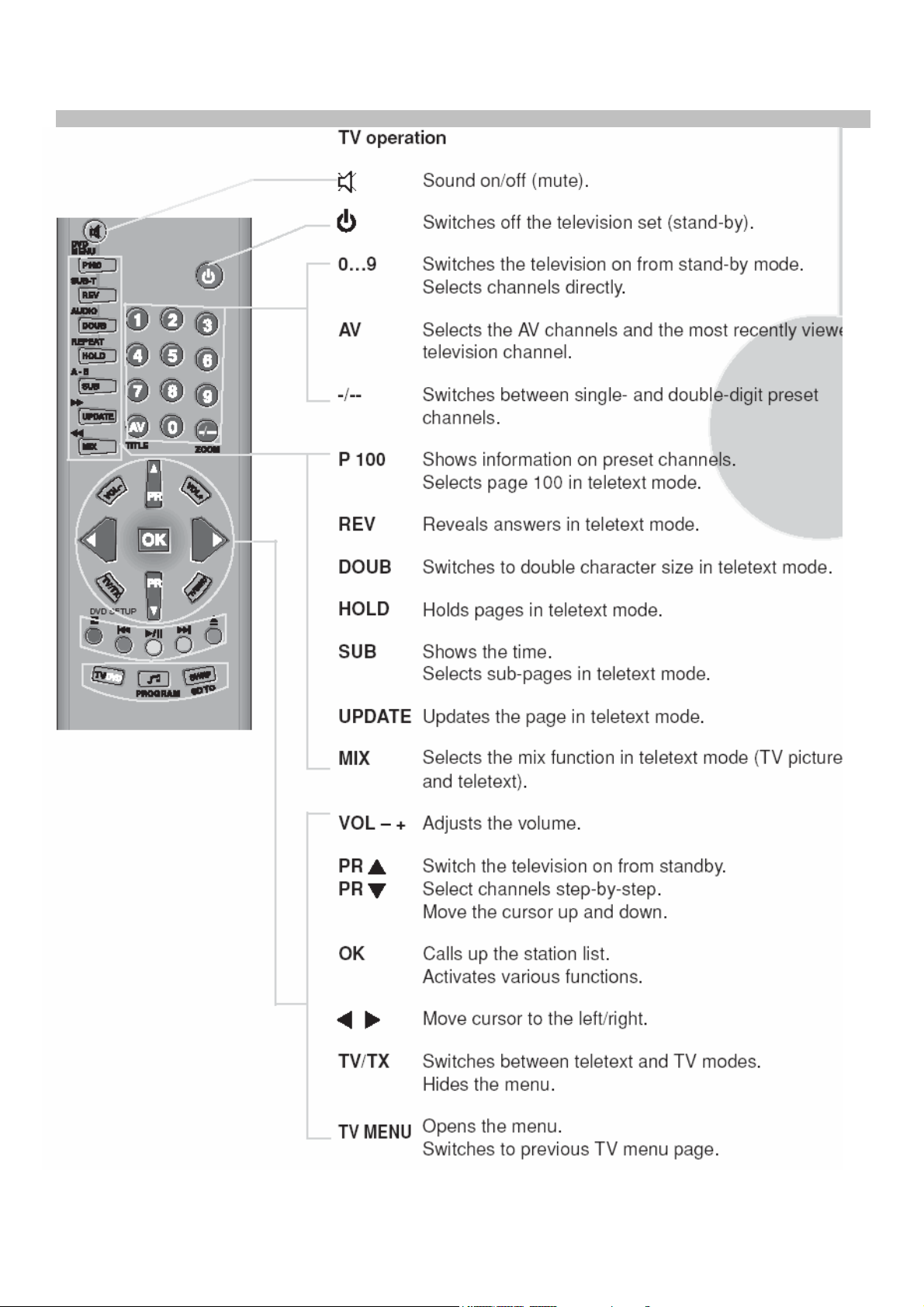
3. REMOTE CONTROL .
4
Page 6
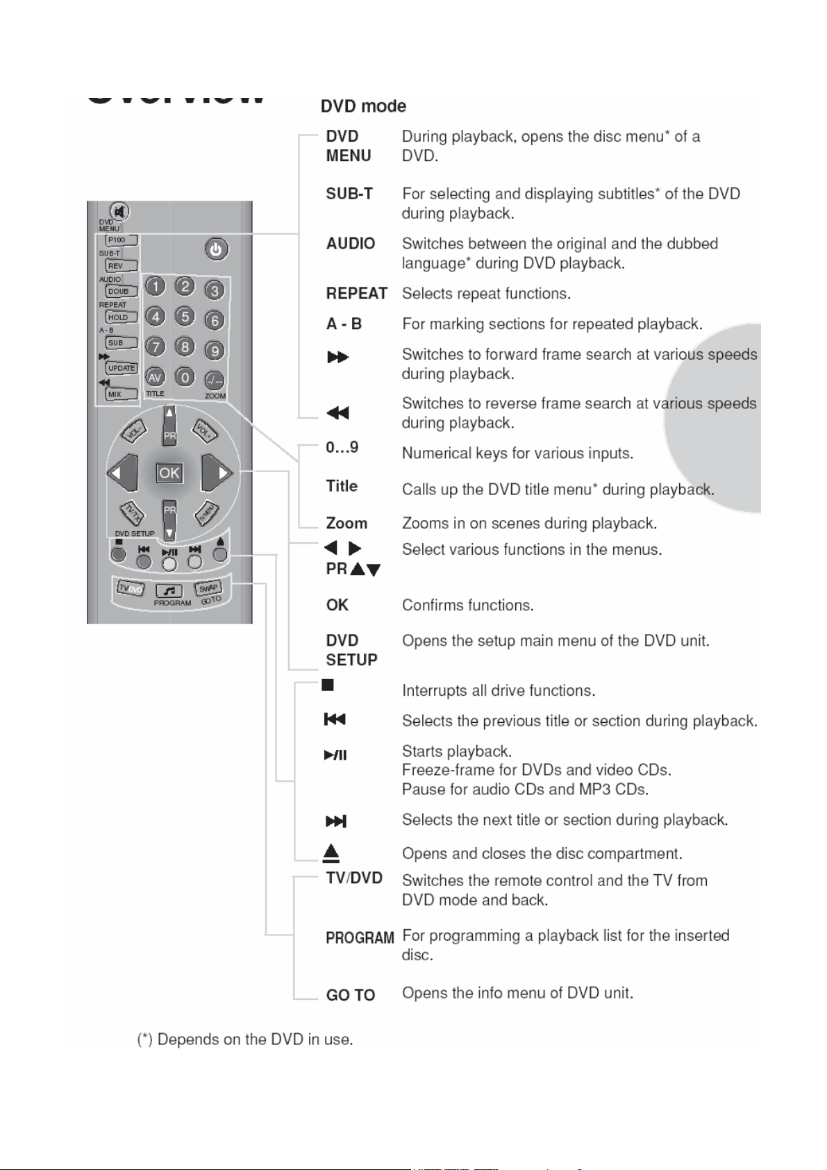
5
Page 7
Special features
• Your TV can receive stereo channels directly (NICAM
optional).
• Automatic tuning system with country selection.
• 100 Programme Memory.
• Available for Cable Channels (A decoder may be required).
• Manual Fine Tuning.
• Child Lock.
• Return to the last viewed channel (SWAP).
• Spatial Sound effect.
• 16:9 picture format.
• S-Video connection (optional).
• Audio/Video RCA sockets (optional).
• Sound adjustment using one button (Smart control).
• Equalizer Sound Setup.
• Automatic Volume Limiting.
• Your TV set is equipped with an On-Screen Display system.
This system enables the user to see the functions on-screen
and to control them efficiently.
• Infrared Remote Control.
• Virtual Dolby Surround (optional).
• Dynamic Bass (optional).
• Multi language menu system.
• On Timer.
• Off Timer.
• Stereo headphone socket (optional).
• 2 Scart Socket: Video cassette recorder, satellite receiver,
video disc player,DVD, TV games or a home computer can be
connected to this AV socket with an appropriate connecting
cable.
• Channel naming.
• Teletext reception.
• Automatic recognition of the broadcasting format (4:3, 16-9)
via WSS feature.
• Channel editing.
• Quick Program Display.
• Alarm function (optional).
• Zoom.
• Freeze.
• MP3 Playback.
• JPEG display.
• Dolby Digital.
• Coaxial output (optional).
• Screen saver.
• SPDIF output.
• Last memory.
• Kid Safe mode.
(*): These features are not available in all models.
6
Page 8

4. PREPARATIONS .
MAIN SUPPLY CONNECTIONS
Connect the TV mains plug into your domestic mains
socket outlet (230 V 50Hz AC).
Press the Program up, Program down button or
Numeric Buttons on the remote handset to switch
• the TV on.
AERIAL CONNECTION
Using a 75Ω aerial lead connect your TV to the
aerial outlet in your home.
BATTERY FITTING
Insert the 2 AAA Batteries supplied into the
compartment on the rear of the remote control,
ensure you follow the polarity diagram inside
the compartment.
4
4
PIN CONNECTIONS FOR SCART SOCKET
1-
Audio output Right 11- RGB input, Green
2- Audio input Right 12-
3- Audio output Left(Mono)13- Red ground
4- Audio ground 14- Ground
5- Blue ground 15- RGB input, Red
6- Audio input Left(Mono) 16- Blanking Signal
7- RGB input, Blue 17- Video output ground
8- Switching voltage 18- Video input ground
9- Green ground 19- Video output
10- 20- Video input
21- Screening
CONNECTING TV WITH VIDEO AND SATELLITE/DIGITALRECEIVER
7
Page 9
5. OPERATING YOUR TV .
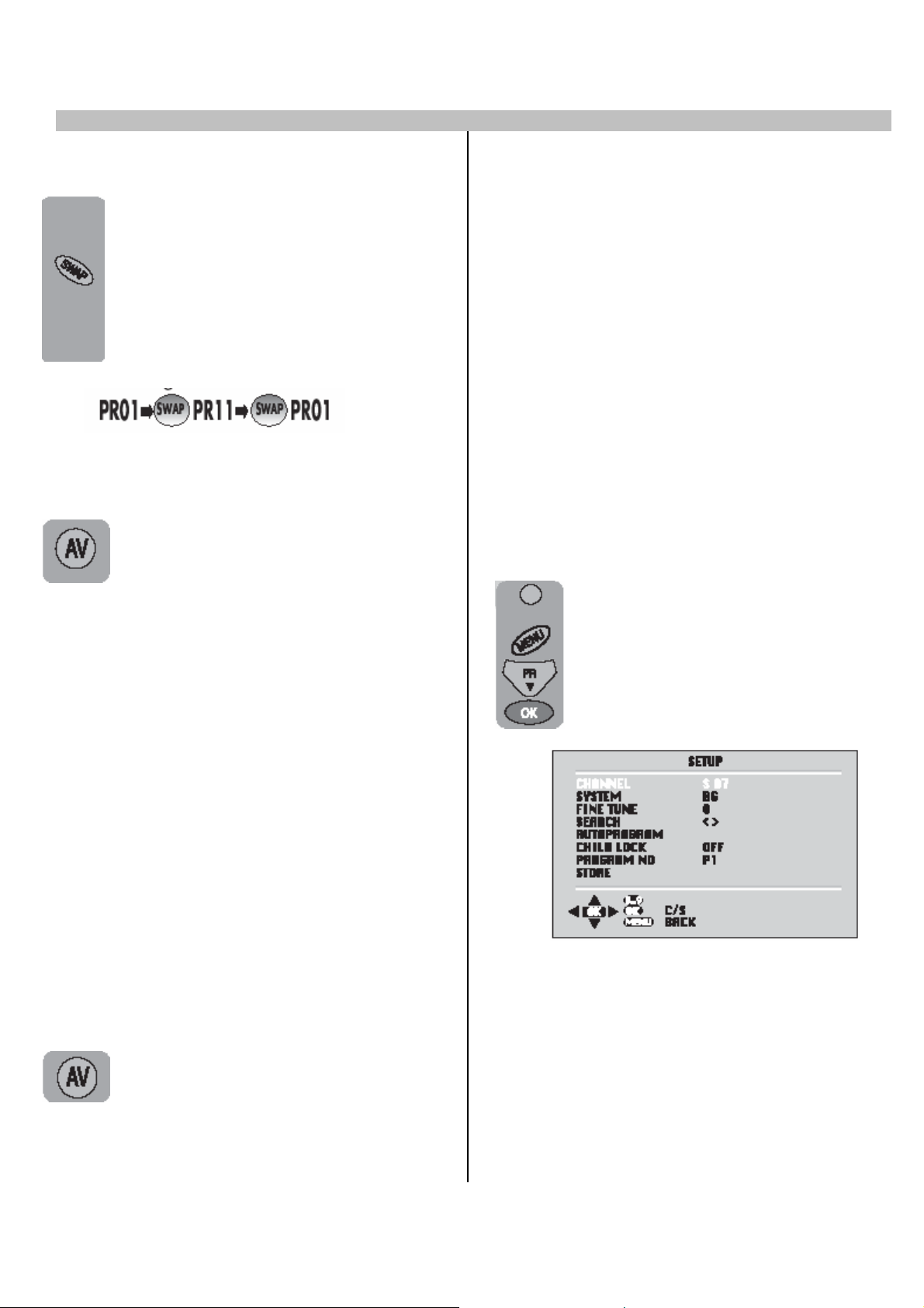
A. SWAP FUNCTION
Allows you to swap between the
program you are watching and the
last selected program. i.e. If you were
watching Program 1 and
change to Program 11, press the
SWAP button to go back to
Program 1. Press it again to return to
Program 11.
C. TUNING THE TELEVISION
There are two ways of tuning your television:
• Manual, where you control the tuning process
or Autoprogram where the television does it all
automatically.
• The TV sets equipped with ATS (Automatic
Tuning System) sorts the channels regarding
the broadcasting system of your country
(optionally).
Please Note
If the TV is set to a channel with no signal the
B. AV
Press theAV button to select your
For use when you are connecting an
external source to your TV (Video
recorder, DVD player etc.) via the SCART
sockets or RCA sockets.
See ‘Connecting external equipment’.
Press the AV button to select your input as
follows:
2 Scart models:
1 AV1 when using SCART socket 1.
TV will return to standby after 5 minutes. The
time remaining is displayed on the screen.
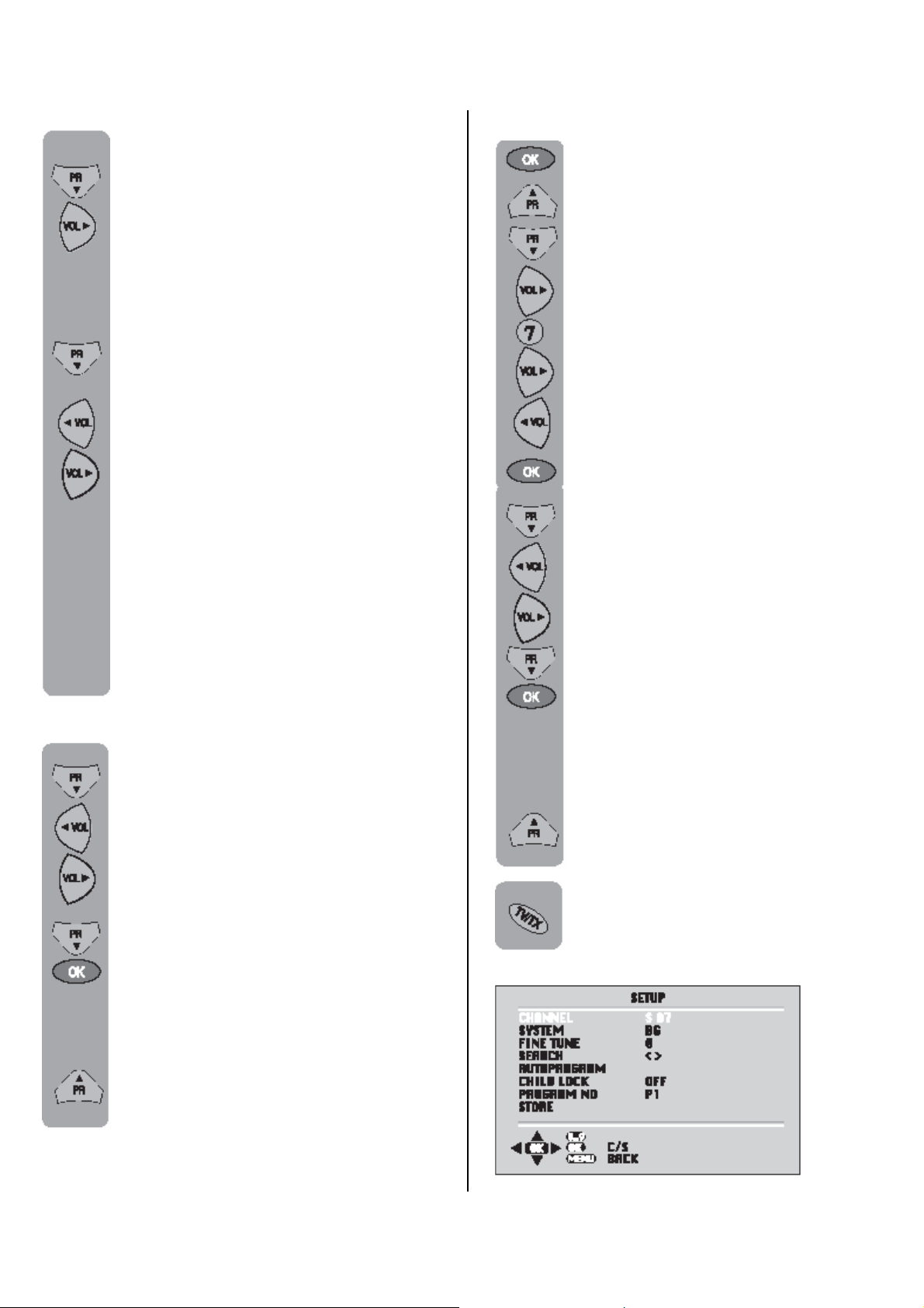
Manual Tuning
Tuning the TV is accessed through the SETUP
menu.
There are two ways to access the SETUP
menu:
Press the blue Setup button or Press
the Menu button and use the
Program down button to select
SETUP. Press the OK button to
enter the SETUP menu.
2 AV2 when using SCART socket 2.
3 AV2-S for S-Video equipment. (Optional)
4 AV3 when using the RCA sockets
of the TV. (Optional)
5 AV3-S when using the S-video socket and
RCA audio sockets of the TV. (Optional)
1 Scart models:
1 AV1 when using SCART socket 1.
2 AV2 when using the RCA sockets of the
TV. (Optional)
3 AV2-S when using the S-video socket and
RCA audio sockets of the TV. (Optional)
Press the AVbutton again to return
toTV
Please note
The system will displayed automatically on
SYSTEM row i.e.BG, L, I, DK depending the
receiving broadcasting system of the country. In
some countries the broadcasting system can be
both in BG/DK or BG/LL´. Only the TV sets
produced with Pal Secam BG/DK or Pal Secam
BG/LL´ systems can receive both BG/DK or
BG/LL´ broadcasts. In this case the user can
select the required SYSTEM using Volume
up/down buttons.
8
Page 10
Please note
If you do not press any buttons for 15
seconds the TV will exit the menu
system.
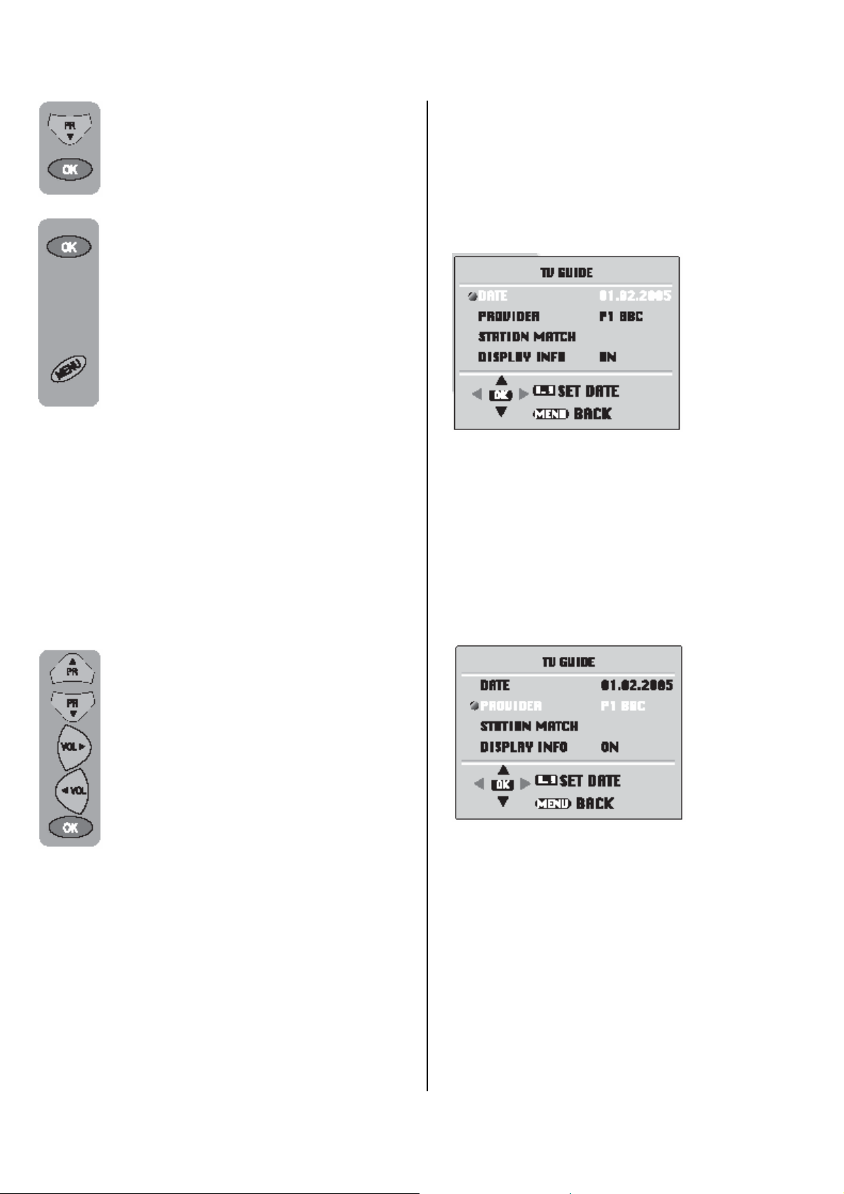
In the Setup menu select PROG NO
and change to P1 using the Program
down button to select it and the
Volume up button to change it.
Starting with Program 1, tune in the
first channel as follows:
Use the Program down button to
select SEARCH.
Press the Volume up or Volume
down button to start the tuning
search.
When the search finds a strong
channel signal it will stop searching.
The picture will appear.
Identify which channel you are
watching (BBC 1, ITV 1 etc.) and
decide which program number you
want it to be.
Use the Program down button to
select PROGRAM NO.
Use the Volume up/down buttons to
select the program number.
Use the Program down button to
select Store. Press theOK button and
STORED will appear on the STORE
line.
Tuning with channel numbers
Enter the SETUP menu by pressing
the blue button. Press the OK button
to enter the CHANNEL row.
Use the OK button to select “S” for
cable channels and “C” for terrestrial
broadcast.
Use Volume up button to select the
channel number buttons.
Enter the channel number using the
Numeric buttons.
Press the Program down/up buttons
to exit the channel row.
Use the Program down button to
select PROGRAM NO.
Use the Volume up/down buttons to
select the program number.
Use the Program down button to
select STORE. Press the OK button
and STORED will appear on the
STORE line.
You have now stored the first
channel.
Use the Program up button to select
again SEARCH and continue the
tuning procedure until you have tuned
in all the programmes you want or the
television can receive.
To exit the SETUP menu press the
TV/TX button.
Automatic tuning (Autoprogram)
Enter the SETUP menu as before.
You have now stored the first
channel.
Use the Program up button to select
again SEARCH and continue the
tuning procedure until you have tuned
in all the programmes you want or the
television can receive.
9
Page 11
Use the Program down button to
select AUTOPROGRAM and the OK
button. A list of Press countries will
appear. Select the desired country
using Program and Volume buttons.
When you are sure the aerial is
connected properly press the OK
button. Autoprogam will start.
To cancel Autoprogram while it
isworking press the Menu button.
Your TV is now tuned and ready to use.
Please note:
If auto sort fails to arrange the programmes in
the required sequence please refer to
programme table.
Fine tuning
Although the search and Autoprogram will
automatically try and tune to the best reception,
in areas of poor reception a bit of fine tuning
may be required.
In the SETUP menu use the Program
up/down buttons to select FINE
TUNE. Use the Volume up and
Volume down buttons to fine tune.
When you have finished use the
Program down button to select
STORE and press the OK button.
D. FEATURES
1-) TV GUIDE(Optional)
You can see the TV Guide information on the
screen by pressing "DOUB" button while a
provider channel or a supported channel by
provider is selected. The information of the
current and next programmes which is sent by
provider is displayed on the screen.
Note: TV Guide information may not have for all
programmes. It depends on the broadcasting
and determined by broadcasting company.
Note: TV Guide is not displayed on the screen,
if there is not a provider in the saved channels.
DATE: Date information is given by provider
channel. You can use the numeric buttons to
change the date.
PROVIDER: Provider is the channel which send
the TV Guide information. You can select the
provider via this function. Press Volume
up/down buttons to select the provider and
then press "OK".
.
STATION MATCH: The supported channels by
provider may not be defined automatically. You
can open this menu and define the provider for
these channels. Adjusting the provider just one
time is enough for these channels.
10
Page 12
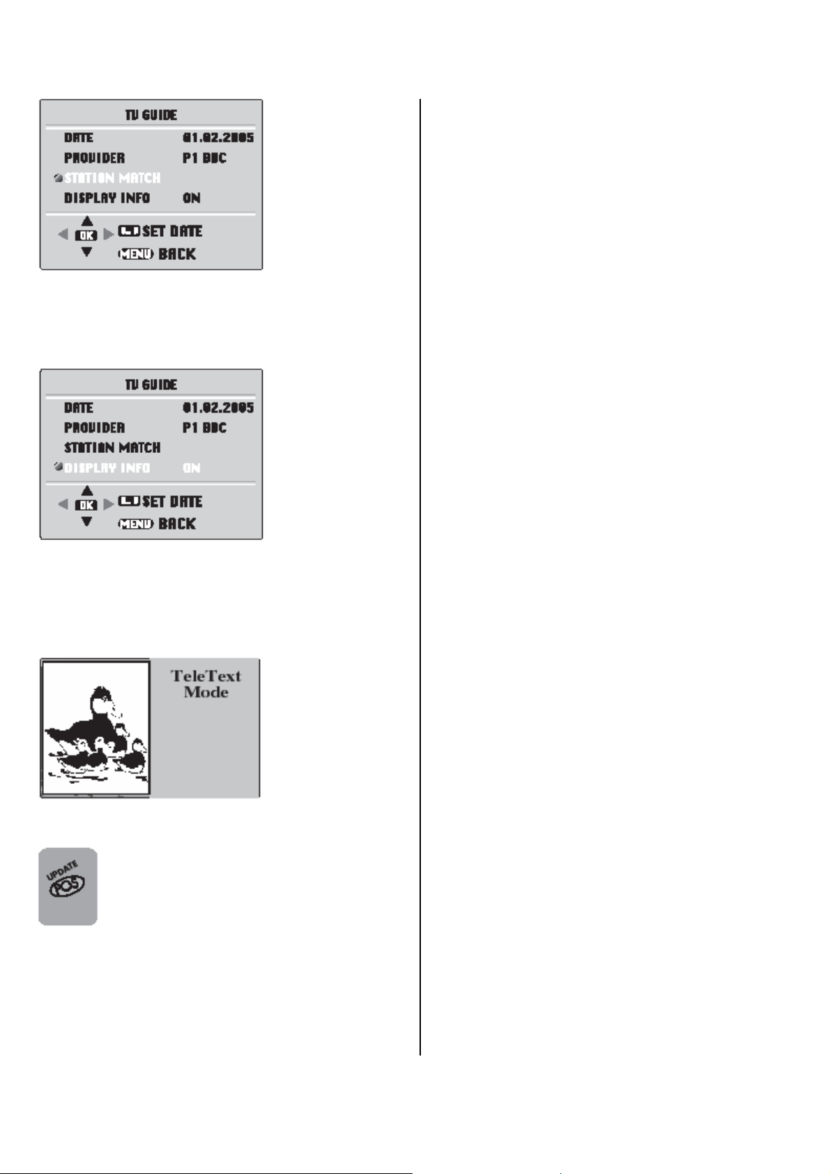
DISPLAY INFO: If you want to see the TV
Guide information automatically while changing
the channels, this option should be open. In this
case, if you open the provider channel Mini
Guide occurs on the screen.
2-) PAT (Picture and Text) (OPTIONAL)
In the double window function, you can also
display the teletext screen in the second
window.
3-) PIP Picture Position Change
Press the POS button repeatedly until
desired position is achieved. The PIP
picture moves clockwise.
11
Page 13

12
Page 14
13
Page 15
14
Page 16
15
Page 17
16
Page 18
17
Page 19
18
Page 20
19
Page 21
20
Page 22
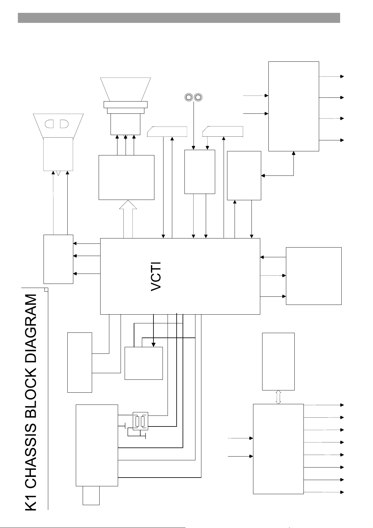
6. K1-K5 ŞASİ BLOK DİAGRAMI .
FBT
TR 502
SCART 1
115 V / 122
SCART 2
2
T
U
O
V
1
T
U
O
V
POWER AMP.
IC 301 AN 5277
AOUT1R
AOUT1L
MUTE
B
R
G
IC 201
SWITCH
MC14052B
T703
RGB IN
54
CVBS OUT
40
30/31/32
Video-Controller-
16
T701, T702,
CRT MODÜLÜ
7
6
71/72/73
47
50
49
FRONT AV
DVD/SCART
CVBS OUT
H-OUT
11
41
10
Family
IC 101
Text-IFAudio IC
14
58
57
17
SAPTIRMA
HORIZONTAL
60
2SD2586
H-SYNC
61
8584 59
VPROT
VDR Q
VDR T
IC 501
SAPTIRMA
TDA 8357
VERTICAL
EHT 45 V 33 V 12 V
KEYBOARD & IR
LED
IR
TUNER
SCL SDA IF1 IF2
AGC
SDA
SCL
EEPROM
WR. PRO.
IC 401
24C16
SDA
SCL
220V AC in
IC 602
ICE1QS01
SMPS CONT.
SMPS
TR601
6.5 V 5 V 3.3 V 1.8 V
115/122 V24 V 12 V 8 V
Page 23
7. IC DATASHEETS&SPECS .
7.1)VCT 49XYI
GENERAL DECRIPTION
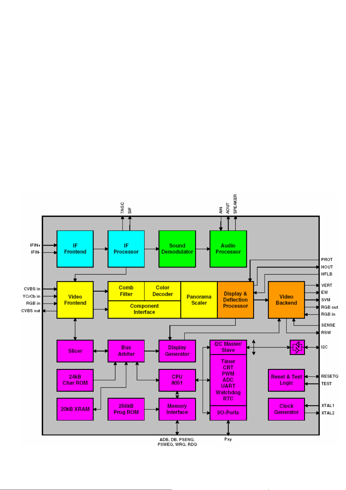
The VCT 49xyI is an IC family of high-quality singlechip TV processors. Modular design and deepsubmicron technology allow the economic integration of features in all classes of single-scan TV sets.
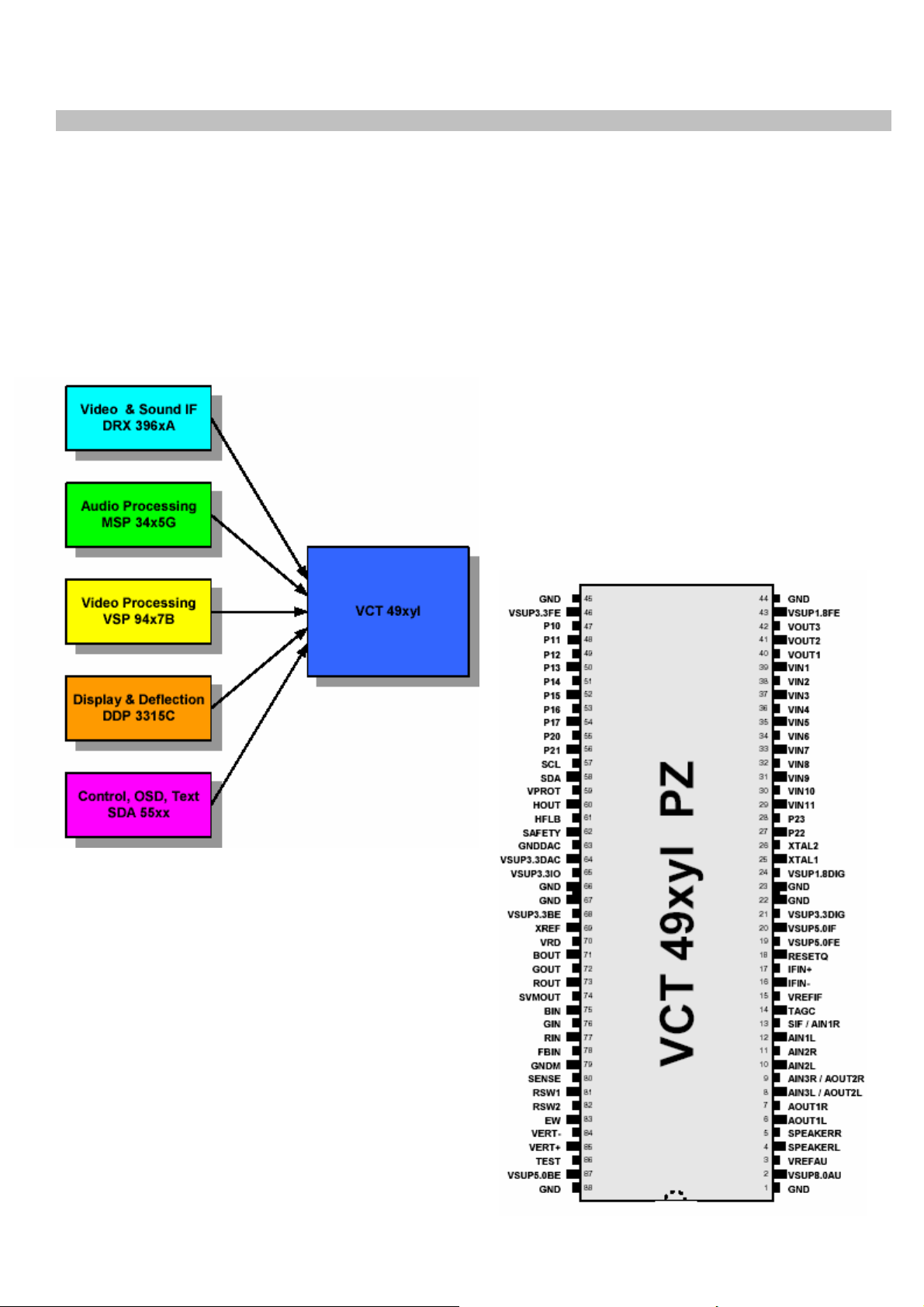
The VCT 49xyI family is based on functional blocks contained and approved in existing products like
DRX 396xA, MSP 34x5G, VSP 94x7B, DDP 3315C, and SDA 55xx.
Each member of the family contains the entire IF, audio, video, display, and deflection processing for
4:3 and 16:9 50/60-Hz mono and stereo TV sets. The integrated microcontroller is supported by a
powerful OSD generator with integrated Teletext & CC acquisition including on-chip page memory.
Features
The VCT 49xyI family offers a rich feature set,
overing the whole range of state-of-the-art
50/60-Hz TV applications.
– PSSDIP88-1/-2 package
– PMQFP144-2 package
– Submicron CMOS technology
– Low-power standby mode
– Single 20.25 MHz reference crystal
– 8-bit 8051 instruction set compatible CPU
– Up to 256 kB on-chip program ROM
– WST, PDC, VPS, and WSS acquisition
– Closed Caption and V-chip acquisition
– Up to 10 pages on-chip teletext memory
– Multi-standard QSS IF processing with single SAW
– FM Radio and RDS with standard TV tuner
– TV-sound demodulation:
• all A2 standards
• all NICAM standards
• BTSC/SAP with MNR (DBX optional)
• EIA-J
– Baseband sound processing for loudspeaker
channel:
• volume and balance
22
Page 24
• bass/treble or equalizer
• loudness and spatial effect (e.g. pseudo stereo)
• Micronas AROUND (virtual Dolby optional)
• Micronas BASS
• further optional and licence requiring sound enhancements as BBE, SRS Wow and Micronas
VOICE
– CVBS, S-VHS, YCrCb and RGB inputs
– 4H adaptive comb filter (PAL/NTSC)
– multi-standard color decoder (PAL/NTSC/SECAM)
– Nonlinear horizontal scaling “panorama vision”
– Luma and chroma transient improvement (LTI, CTI)
– Non-linear color space enhancement (NCE)
– Dynamic black level expander (BLE)
– Scan velocity modulation output
– Soft start/stop of H-drive
– Vertical angle and bow correction
– Average and peak beam current limiter
– Nonlinear and dynamic EHT compensation
– Black switch off procedure (BSO)
23
Page 25
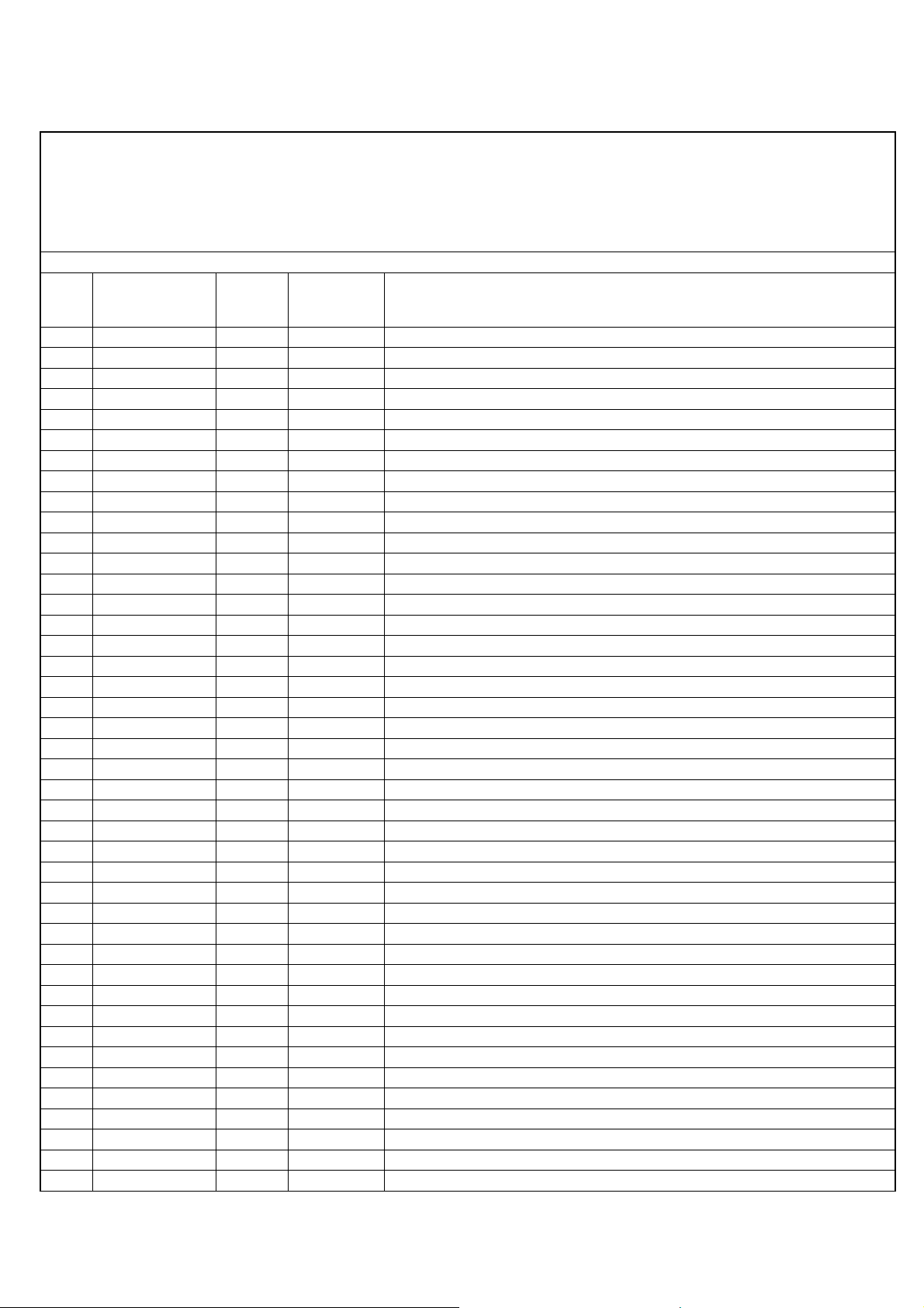
PIN CONNECTIONS AND SHORT DESCRIPTIONS
NC = not connected
LV = if not used, leave vacant
OBL = obligatory; connect as described in circuit diagram
IN = Input Pin
OUT = Output Pin
SUPPLY = Supply Pin
Connection
Pin
No Pin Name Type
1 GND SUPPLY OBL Ground Platform
2 VSUP8.0AU SUPPLY OBL Supply Voltage Analog Audio, 8.0 V
3 VREFAU OBL Reference Voltage, Audio
4 SPEAKERL OUT LV Analog Loudspeaker Output, Right
5 SPEAKERR OUT LV Analog Loudspeaker Output, Right
6 AOUT1L OUT LV Analog Audio 1 Output, Left
7 AOUT1R OUT LV Analog Audio 1 Output, Right
8 AIN3L/AOUT2L IN/OUT LV Analog Audio 3 Input, Left / Analog Audio 2 Output, Left
9 AIN3R/AOUT2R IN/OUT LV Analog Audio 3 Input, Right / Analog Audio 2 Output, Right
10 AIN2L IN GND Analog Audio 2 Input, Left
11 AIN2R IN GND Analog Audio 2 Input, Right
12 AIN1L IN GND Analog Audio 1 Input, Left
13 AIN1R/SIF IN/OUT GND Analog Audio 1 Input Right/Analog 2nd Sound IF Output
14 TAGC OUT LV Tuner AGC Output
15 VREFIF OBL Reference Voltage, IF ADCs
16 IFIN- IN VREFıf Differential IF Input
17 IFIN+ IN VREFıf Differential IF Input
18 RESETQ IN/OUT OBL Reset Input/Output
19 VSUP5.0FE SUPPLY OBL Supply Voltage Analog IF Front-end, 5.0 V
20 VSUP5.0IF SUPPLY OBL Supply Voltage IF ADC, 5.0 V
21 VSUP3.3DIG SUPPLY OBL Supply Voltage Digital Core, 3.3 V
22 GND SUPPLY OBL Ground Platform
23 GND SUPPLY OBL Ground Platform
24 VSUP1.8DIG SUPPLY OBL Supply Voltage Digital Core, 1.8 V (main and stand by supply)
25 XTAL1 IN OBL Analog Crystal Input
26 XTAL2 OUT OBL Analog Crystal Output
27 P22 IN/OUT LV Port 2, Bit 2 Input/Output
28 P23 IN/OUT LV Port 2, Bit 3 Input/Output
29 VIN11 IN GND Analog Video 11 Input
30 VIN10 IN GND Analog Video 10 Input
31 VIN9 IN GND Analog Video 9 Input
32 VIN8 IN GND Analog Video 8 Input
33 VIN7 IN GND Analog Video 7 Input
34 VIN6 IN GND Analog Video 6 Input
35 VIN5 IN GND Analog Video 5 Input
36 VIN4 IN GND Analog Video 4 Input
37 VIN3 IN GND Analog Video 3 Input
38 VIN2 IN GND Analog Video 2 Input
39 VIN1 IN GND Analog Video 1 Input
40 VOUT1 OUT LV Analog Video 1 Output
41 VOUT2 OUT LV Analog Video 2 Output
42 VOUT3 OUT LV Analog Video 3 Output
(If not
used) Short Description
24
Page 26

Supply Voltage Analog Video Front-end, 1.8 V (main and stand by
43 VSUP1.8FE SUPPLY OBL
44 GND SUPPLY OBL Ground Platform
45 GND SUPPLY OBL Ground Platform
46 VSUP3.3FE SUPPLY OBL
47 P10 IN/OUT LV Port 1, Bit 0 Input/Output
48 P11 IN/OUT LV Port 1, Bit 1 Input/Output
49 P12 IN/OUT LV Port 1, Bit 2 Input/Output
50 P13 IN/OUT LV Port 1, Bit 3 Input/Output
51 P14 IN/OUT LV Port 1, Bit 4 Input/Output
52 P15 IN/OUT LV Port 1, Bit 5 Input/Output
53 P16 IN/OUT LV Port 1, Bit 6 Input/Output
54 P17 IN/OUT LV Port 1, Bit 7 Input/Output
55 P20 IN/OUT LV Port 2, Bit 0 Input/Output
56 P21 IN/OUT LV Port 2, Bit 1 Input/Output
57 SCL IN/OUT OBL I²C Bus Clock Input/Output
58 SDA IN/OUT OBL I²C Bus Data Input/Output
59 VPROT IN GND Vertical Protection Input
60 HOUT OUT LV Horizontal Drive Output
61 HFLB IN HOUT Horizontal Flyback Input
62 SAFETY IN GND Safety Input
63 GNDDAC SUPPLY OBL Ground Video DACs
64 VSUP3.3DAC SUPPLY OBL Supply Voltage Video DACs, 3.3 V
65 VSUP3.3IO SUPPLY OBL Supply Voltage I/O Ports, 3.3 V (main and Standby supply)
66 GND SUPPLY OBL Ground Platform
67 GND SUPPLY OBL Ground Platform
68 VSUP3.3BE SUPPLY OBL Supply Voltage Analog Video Back-end, 3.3 V
69 XREF OBL Reference Current for RGB DACs
70 VRD OBL Reference Voltage for RGB DACs
71 BOUT OUT VSUP5.0BE Analog Blue Output
72 GOUT OUT VSUP5.0BE Analog Green Output
73 ROUT OUT VSUP5.0BE Analog Red Output
74 SVMOUT OUT VSUP5.0BE Scan Velocity Modulation Output
75 BIN IN GND Analog Blue Input, Back-end
76 GIN IN GND Analog Green Input, Back-end
77 RIN IN GND Analog Red Input, Back-end
78 FBIN IN GND Fast Blank Input, Back-end
79 GNDM IN GND Reference Ground for Sense ADC
80 SENSE IN GND Sense ADC Input
81 RSW1 OUT LV Range Switch 1 Output
82 RSW2 OUT LV Range Switch 2 Output
83 EW OUT GND Vertical Parabola Output
84 VERT- OUT GND Differential Vertical Sawtooth Output
85 VERT+ OUT GND Differential Vertical Sawtooth Output
86 TEST IN GND Test Input, reserved for Test
87 VSUP5.0BE SUPPLY OBL Supply Voltage Analog Video Back-end, 5.0 V
88 GND SUPPLY OBL Ground Platform
supply)
Supply Voltage Analog Video Front-end, 3.3 V (main and stand by
supply)
25
Page 27
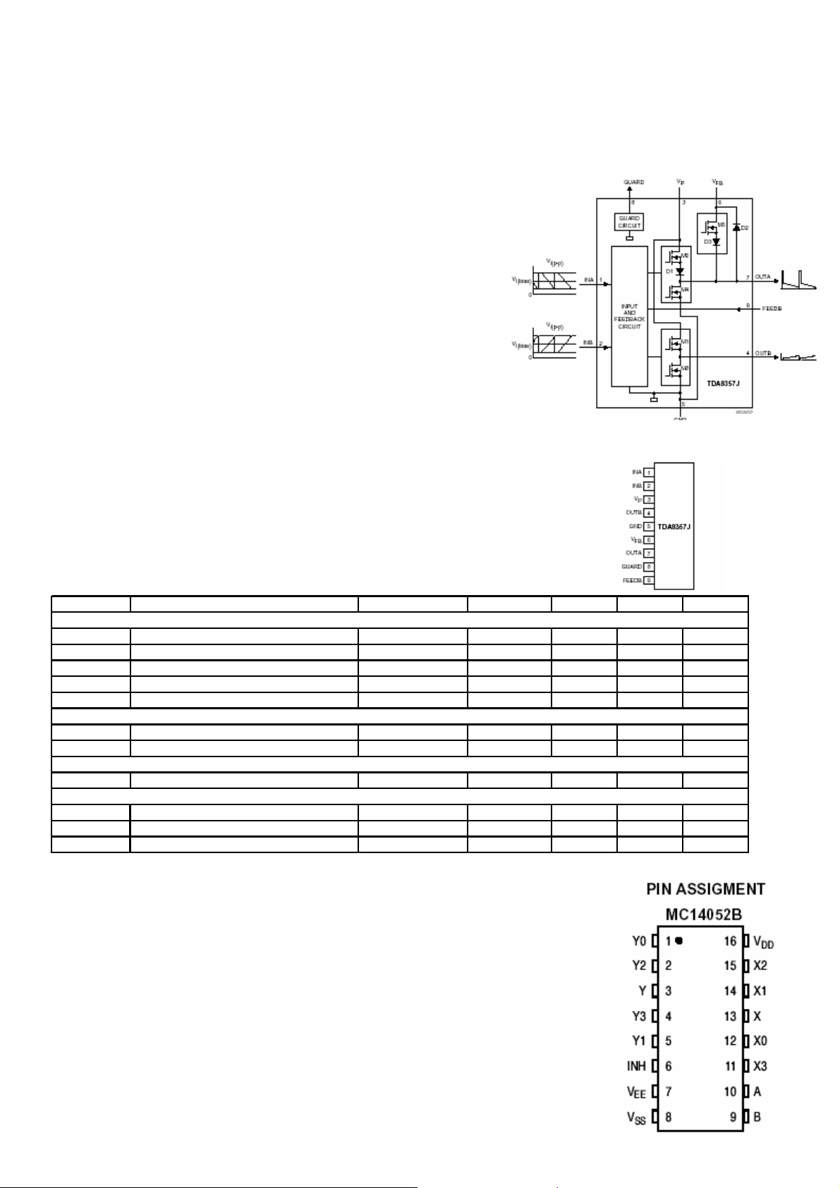
7.2)TDA 8357
GENERAL DESCRIPTION
The TDA8357J is a power circuit for use in 90° and
110° colour deflection systems for 25 to 200 Hz field
frequencies, and for 4 : 3 and 16 : 9 picture tubes. The IC
contains a vertical deflection output circuit, operating as a
high efficiency class G system. The full bridge output
circuit allows DC coupling of the deflection coil in
combination with single positive supply voltages.
The IC is constructed in a Low Voltage DMOS (LVDMOS)
process that combines bipolar, CMOS and DMOS
devices. DMOS transistors are used in the output stage
because of absence of second breakdown.
FEATURES
• Few external components required
• High efficiency fully DC coupled vertical bridge outputcircuit
• Vertical flyback switch with short rise and fall times
• Built-in guard circuit
• Thermal protection circuit
• Improved EMC performance due to differential inputs
SYMBOL PARAMETERS CONDITIONS MIN. TYP. MAX UNIT
Supplies
Vp Supply voltage 7.5 12 18 V
VFB flyback supply voltage 2 x VP 45 66 V
Iq(P)(av) average quiescent supply current during scan - 10 15 mA
Iq(FB)(av) Iq(FB)(av) during scan - - 10 mA
Ptot total power dissipation - - 8 W
Inputs and outputs
Vi(p-p) input voltage (peak-to-peak value) - 1000 1500 mV
Io(p-p) output current (peak-to-peak value) - - 2.0 A
Flyback switch
Io(peak) maximum (peak) output current
Thermal data; in accordance with IEC 60747-1
Tstg storage temperature -55 - +150
Tj junction temperature - - +150
t ≤ 1.5 ms
--± 1.2A
7.3)MC14052B
The MC14052B analog multiplexer is a digitally–controlled analog switch.
The MC14052B effectively implements a DP4T solid state switch. This
device’s feature low ON impedance and very low OFF leakage current.
Control of analog signals up to the complete supply voltage range can be
achieved.
• Triple Diode Protection on Control Inputs
• Switch Function is Break Before Make
• Supply Voltage Range = 3.0 Vdc to 18 Vdc
ºC
ºC
26
Page 28
• Analog Voltage Range (VDD – VEE) = 3.0 to 18 V Note: VEE must be _ VSS
• Linearized Transfer Characteristics
• Low–noise – 12 nV//Cycle, f . 1.0 kHz Typical
This device contains protection circuitry to guard against damage due to high static voltages or electric
fields. However, precautions must be taken to avoid applications of any voltage higher than maximum
rated voltages to this high–impedance circuit. For proper operation, Vin and Vout should be constrained
to the range VSS _ (Vin or Vout) _ VDD. Unused inputs must always be tied to an appropriate logic
voltage level (e.g., either VSS, VEE or VDD). Unused outputs must be left open.
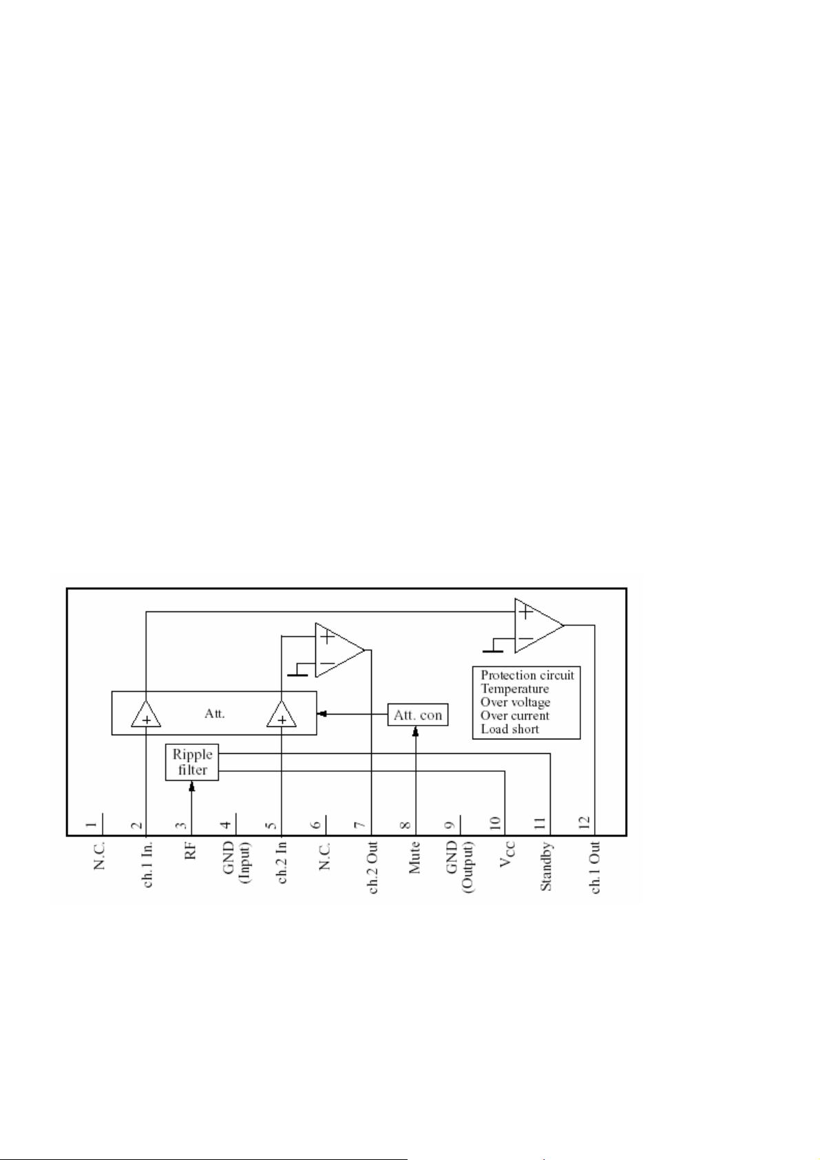
7.4)AN5277(Dual Channel SEPP Power Amplifier)
The AN5277 is a monolithic integrated circuit designed for 10.0 W (26 V, 8 W)output audio power
amplifier. It is a dual channel SEPP IC suitable for stereo operation in TV application.
Features
• Few external components :
• No Boucherot cells(output C, R)
• No Bootstrap Capacitors
• No Negative Feedback Capacitors
• Built-in muting circuit
• Built-in standby circuit
• Built-in various protection circuits (Load-short, thermal, over-voltage and current)
• High ripple rejection(55 dB)
• Compatible with AN5275, AN5276
• Operating voltage range 10 ~ 32 V(26 V typ.)
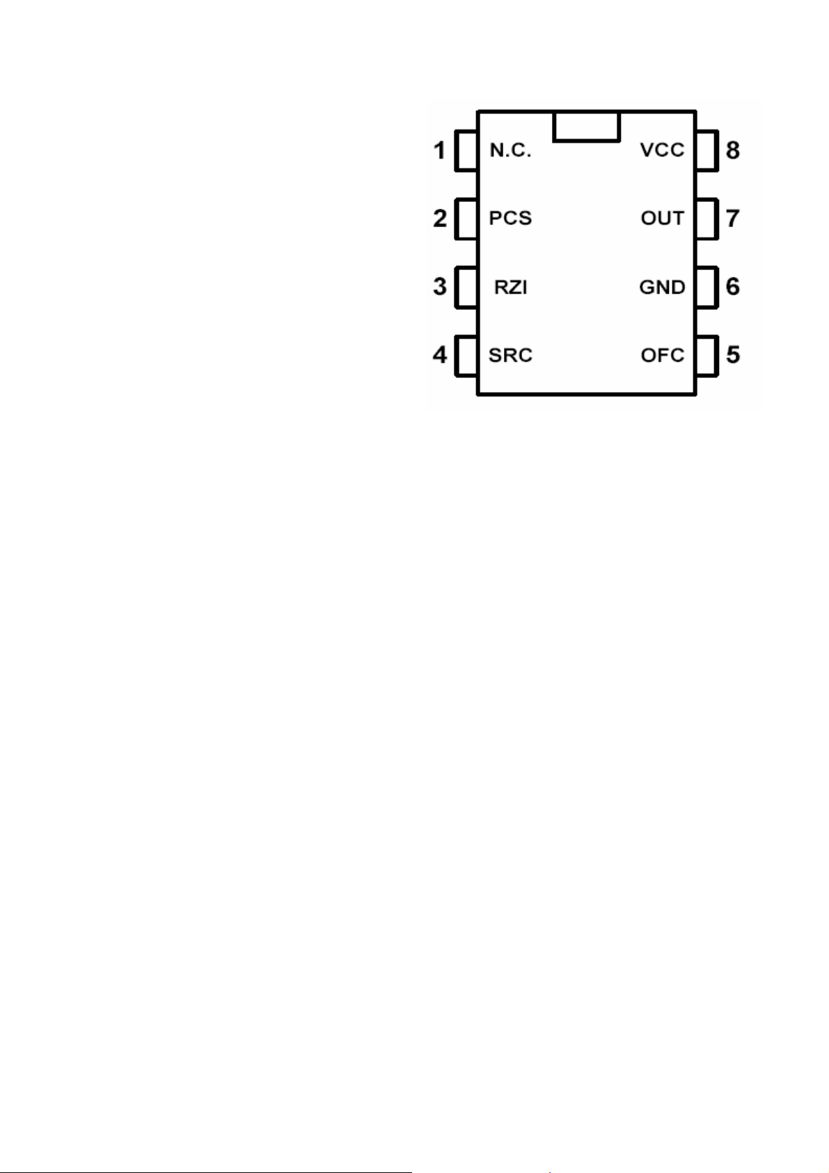
7.5)ICE1QS01(Controller for Switch Mode Power Supplies Supporting Low Power
Standby and Power Factor Correction (PFC))
Features
• Line Current Consumption with PFC
• Standby Input Power < 1 W
• Stable Standby Frequency
27
Page 29
• Low Power Consumption
• Very Low Start-up Current
• Soft-Start for noiseless Start-up
• Standby Burst Mode with and without
Control Signal for lowered Output Voltages
• Digital Frequency Reduction in small Steps
at Decreasing Load
• Over- and Undervoltage Lockout
• Switch Off at Mains Undervoltage
• Mains Voltage Dependent Fold Back Point
Correction
• Ringing Suppression Time Controlled from
Output Voltage
• Easy Design In
• Free usable Fault Comparator
Functional Description
The ICE1QS01 is optimized to control free running flyback converters with and without Power Factor
Correction (with PFC Charge Pump). The switching frequency is reduced in small steps with
decreasing load towards a minimum of 20 kHz in standby mode. This function is performed by a digital
circuit to avoid any jitter also with periodically pulsed loads. To provide extremely low power
consumption at light loads, this device can be switched into Standby Burst Mode. This is also possible
without standby control signal (for adapter application). Additionally, the start up current is very low. To
avoid switching stresses of the power devices, the power transistor is always switched on at minimum
voltage. The device has several protection functions: VCC overand undervoltage, mains undervoltage
and current limiting. Regulation can be done by using the internal error amplifier or an opto coupler
feedback. The output driver is ideally suited for driving a power MOSFET. The ICE1QS01 is suited for
TV-sets, VCR- sets, SAT- receivers and other consumer applications in the power range from 0 to app.
300 W.
28
Page 30
8. PIN VOLTAGES OF IC’S .
IC 101(VCTI)
Video-Controller-Text-IFAudio IC Family
Pin
No
Pin Name Short Description
1 GND Ground Platform 0 0 45 GND Ground Platform 0 0
2 VSUP8.0AU Supply Voltage Analog Audio, 8.0 V 8,13 1,35 46 VSUP3.3FE
3 VREFAU Reference Voltage, Audio 3,67 0 47 P10 Port 1, Bit 0 Input/Output 3,27 0
4 SPEAKERL Analog Loudspeaker Output, Right 3,72 0 48 P11 Port 1, Bit 1 Input/Output 0 3,27
5 SPEAKERR Analog Loudspeaker Output, Right 3,72 0 49 P12 Port 1, Bit 2 Input/Output 3,3 3,29
6 AOUT1L Analog Audio 1 Output, Left 3,72 0 50 P13 Port 1, Bit 3 Input/Output 0 3,28
7 AOUT1R Analog Audio 1 Output, Right 3,72 0 51 P14 Port 1, Bit 4 Input/Output 0 0
8 AIN3L/AOUT2L
9 AIN3R/AOUT2R
10 AIN2L Analog Audio 2 Input, Left 3,7 0 54 P17 Port 1, Bit 7 Input/Output 2,79 2,79
11 AIN2R Analog Audio 2 Input, Right 3,7 0 55 P20 Port 2, Bit 0 Input/Output 3,32 2,9
12 AIN1L Analog Audio 1 Input, Left 3,7 0 56 P21 Port 2, Bit 1 Input/Output 3,24 0,6
13 AIN1R/SIF
14 TAGC Tuner AGC Output 3,77 0,82 58 SDA I²C Bus Data Input/Output 3,3 3,06
15 VREFIF Reference Voltage, IF ADCs 2,42 0,9 59 VPROT Vertical Protection Input 0,05 0
16 IFIN- Differential IF Input 2,43 0,76 60 HOUT Horizontal Drive Output 1,55 3,29
17 IFIN+ Differential IF Input 2,43 0,76 61 HFLB Horizontal Flyback Input 0,65 0
18 RESETQ Reset Input/Output 3,29 3,27 62 SAFETY Safety Input 0,03 0,43
19 VSUP5.0FE
20 VSUP5.0IF Supply Voltage IF ADC, 5.0 V 4,92 1 64 VSUP3.3DAC Supply Voltage Video DACs, 3.3 V 3,29 1
21 VSUP3.3DIG Supply Voltage Digital Core, 3.3 V 3,14 1 65 VSUP3.3IO
22 GND Ground Platform 0 0 66 GND Ground Platform 0 0
23 GND Ground Platform 0 0 67 GND Ground Platform 0 0
24 VSUP1.8DIG
25 XTAL1 Analog Crystal Input 1,71 1,7 69 XREF Reference Current for RGB DACs 1,22 0
26 XTAL2 Analog Crystal Output 1,74 1,72 70 VRD Reference Voltage for RGB DACs 1,24 0,95
27 P22 Port 2, Bit 2 Input/Output 3,27 3,26 71 BOUT Analog Blue Output 4,66 1
28 P23 Port 2, Bit 3 Input/Output 3,27 3,26 72 GOUT Analog Green Output 4,66 1
29 VIN11 Analog Video 11 Input 0,12 0,09 73 ROUT Analog Red Output 4,66 1
30 VIN10 Analog Video 10 Input 0 0,09 74 SVMOUT Scan Velocity Modulation Output 1,77 0,37
31 VIN9 Analog Video 9 Input 0,5 0,09 75 BIN Analog Blue Input, Back-end 0,19 0
32 VIN8 Analog Video 8 Input 0,5 0,09 76 GIN Analog Green Input, Back-end 0,19 0
33 VIN7 Analog Video 7 Input 0,99 0,09 77 RIN Analog Red Input, Back-end 0,19 0
34 VIN6 Analog Video 6 Input 0,99 0,09 78 FBIN Fast Blank Input, Back-end 0,07 0,07
35 VIN5 Analog Video 5 Input 0,99 0,09 79 GNDM Reference Ground for Sense ADC 0 0
36 VIN4 Analog Video 4 Input 1 0,09 80 SENSE Sense ADC Input 0,23 0
37 VIN3 Analog Video 3 Input 1 0,09 81 RSW1 Range Switch 1 Output 0,03 0
38 VIN2 Analog Video 2 Input 1 0,09 82 RSW2 Range Switch 2 Output 0,01 0
39 VIN1 Analog Video 1 Input 1 0,09 83 EW Vertical Parabola Output 4,37 0
40 VOUT1 Analog Video 1 Output 1,08 1,49 84 VERT- Differential Vertical Sawtooth Output 0,82 0
41 VOUT2 Analog Video 2 Output 1,08 1,49 85 VERT+ Differential Vertical Sawtooth Output 0,79 0
42 VOUT3 Analog Video 3 Output 1,17 0,98 86 TEST Test Input, reserved for Test 3,71 0
43 VSUP1.8FE
44 GND Ground Platform 0 0 88 GND Ground Platform 0 0
Analog Audio 3 Input, Left / Analog
Audio 2 Output, Left
Analog Audio 3 Input, Right / Analog
Audio 2 Output, Right
Analog Audio 1 Input Right/Analog
2nd Sound IF Output
Supply Voltage Analog IF Front-end,
5.0 V
Supply Voltage Digital Core, 1.8 V
(main and stand by supply)
Supply Voltage Analog Video Frontend, 1.8 V 1,9 1,9 87 VSUP5.0BE
V DC
3,43 0 52 P15 Port 1, Bit 5 Input/Output 0 0
3,44 0 53 P16 Port 1, Bit 6 Input/Output 2,77 2,77
3,7 0 57 SCL I²C Bus Clock Input/Output 3,3 3,06
4,96 1 63 GNDDAC Ground Video DACs 0 0
1,85 1,97 68 VSUP3.3BE
Pin
No
Pin Name Short Description
ST-BY
Supply Voltage Analog Video Frontend, 3.3 V
Supply Voltage I/O Ports, 3.3 V
(main and Standby supply)
Supply Voltage Analog Video Backend, 3.3 V
Supply Voltage Analog Video Backend, 5.0 V 5,01 0
V DC
ST-BY
3,3 3,3
3,31 3,31
3,28 1
29
Page 31
IC 301(AN 5277)
Dual Channel SEPP Power Amplifier
Pin
No
Pin Name Short Description
1 N.C NOT CONNECTED 0 0 7 CH.2 OUT CHANNEL 2 OUTPUT 12 0
2 CH.1 IN. CHANNEL 1 INPUT 0 0 8 MUTE MUTE 0,37 4,44
3 RF RIPPLE FILTER 23,1 0,76 9 GND(OUTPUT) OUTPUT GROUND 0 0
4 GND(INPUT) INPUT GROUND 0 0 10 Vcc Vcc 25,3 8,47
5 CH.2 IN CHANNEL 2 INPUT 0 0 11 ST-BY STANDBY 16,5 0,43
6 N.C NOT CONNECTED 0 0 12 CH.1 OUT CHANNEL 1 OUTPUT 12 0
V DC
Pin
No
ST-BY
Pin Name Short Description
V DC
ST-BY
IC 602(ICE1QS01)
Dual Channel SEPP Power Amplifier
Pin
No Pin Name Short Description
1 N.C NOT CONNECTED 0 0 5 OFC
2 PCS PRIMARY CURRENT SIMULATION 1,3 9,06 6 GND GROUND 0 0
REGULATION AND ZERO CROSSING
3 RZI
4 SRC
INPUT
SOFT-START AND REGULATION
CPACITOR
V DC
1,35 0,04 7 OUT OUTPUT 1,79 0
2,76 0,34 8 Vcc SUPPLY VOLTAGE 11,4 10,1
Pin
No Pin Name Short Description
ST-BY
OVERVOLTAGE FAULT
COMPARATOR 0 0
V DC
ST-BY
IC 501(TDA 8357)
VERTICAL DEFLECTION
Pin
No
Pin Name Short Description
1 INA INPUT A 0,79 0 6 Vfb FLAYBACK SUPPLY COLTAGE 46,5 0
2 INB INPUT B 0,77 0 7 OUTA OUTPUT A 6,46 0
3 Vp SUPPLY VOLTAGE 12,4 0 8 GUARD GUARD OUTPUT 0,25 0
4 OUTB OUTPUT B 6,5 0 9 FEEDB FEEDBACK INPUT 6,55 0
5 GND GROUND 0 0
V DC
Pin
No
ST-BY
Pin Name Short Description
V DC
ST-BY
30
Page 32
9. OSCILLOSGRAPHS OF SOME IC PINS .
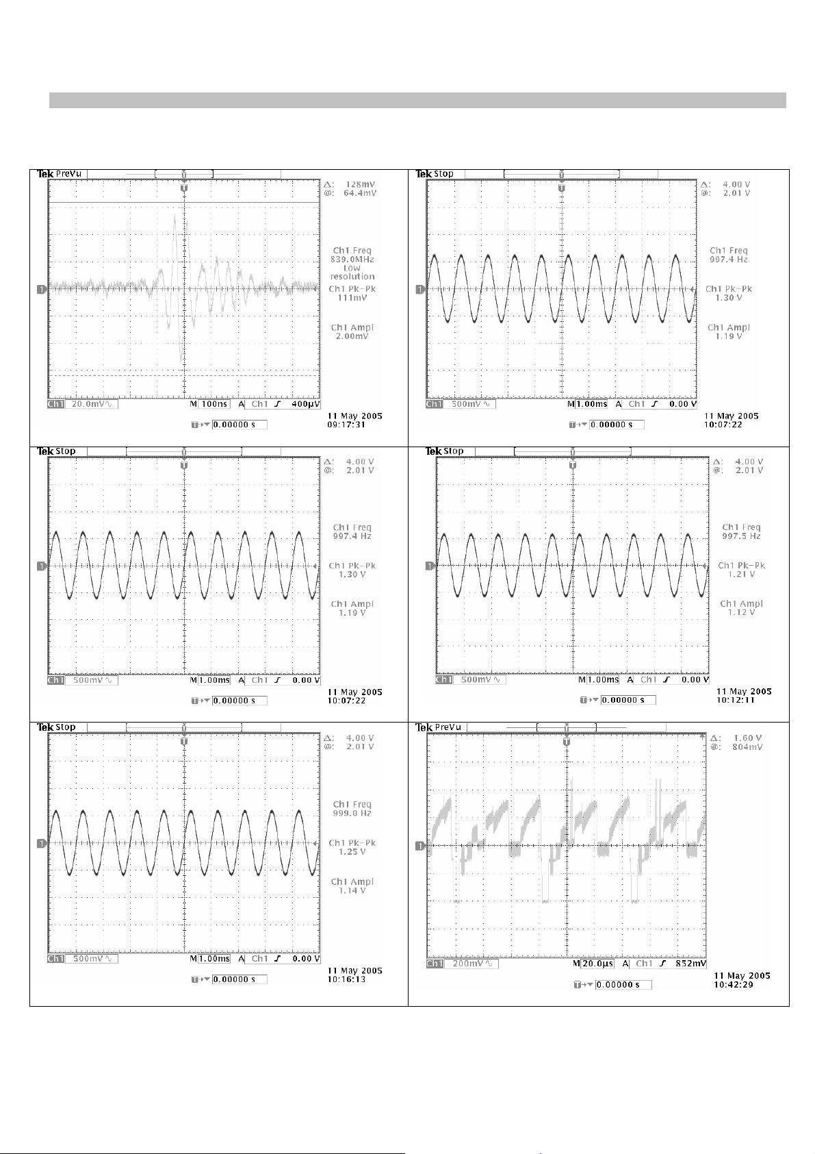
Note : A pattern Generator is connected to the TV (Colour Bar, sound 1 kHZ)
9.1 VCTI-IC 101
Pin 02, Supply Voltage Analog Audio, 15625 kHz
Pin 07, Analog Audio Output, Right, 15625 kHz
Pin 06, Analog Audio 1 Output, Left, 15625 kHz
Pin 08, Analog Audio 3 Input,Left, 15625 kHz
Pin 09, Analog Audio 3 Input,Right, 15625kHz
Pin 38, Analog Video 2 Input, 15625kHz
31
Page 33
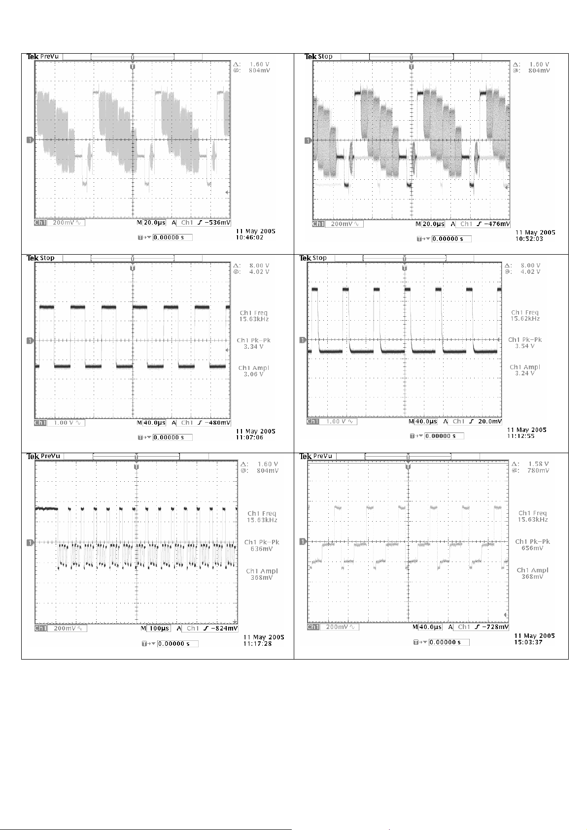
Pin 40, Analog Video 1 Output, 15625 kHz
Pin 41, Analog Video 2 Output, 15625 kHz
Pin 60, Horizontal Drive Ouput, 15625 kHz
Pin 71, Analog Blue Ouput, 15625 kHz
Pin 61, Horizontal Fylback Input, 15625 kHz
Pin 72, Analog Green Ouput 15625 kHz
32
Page 34
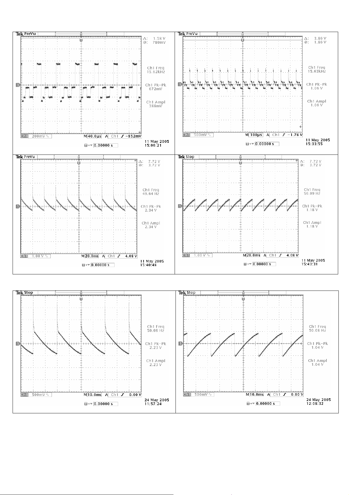
Pin 73, Analog Red Ouput, 15625 kHz
Pin 80, Sense ADC Input, 15625 kHz
Pin 84,Differential Vert. Sawtooth Out(VERT-), 15625 kHz
9.2 TDA 2822-IC 301
Pin 1, Input A, 15625 kHz
Pin 85, Differential Vert. Sawtooth Out(VERT+), 15625 kHz
Pin 2, Input B, 15625 kHz
33
Page 35
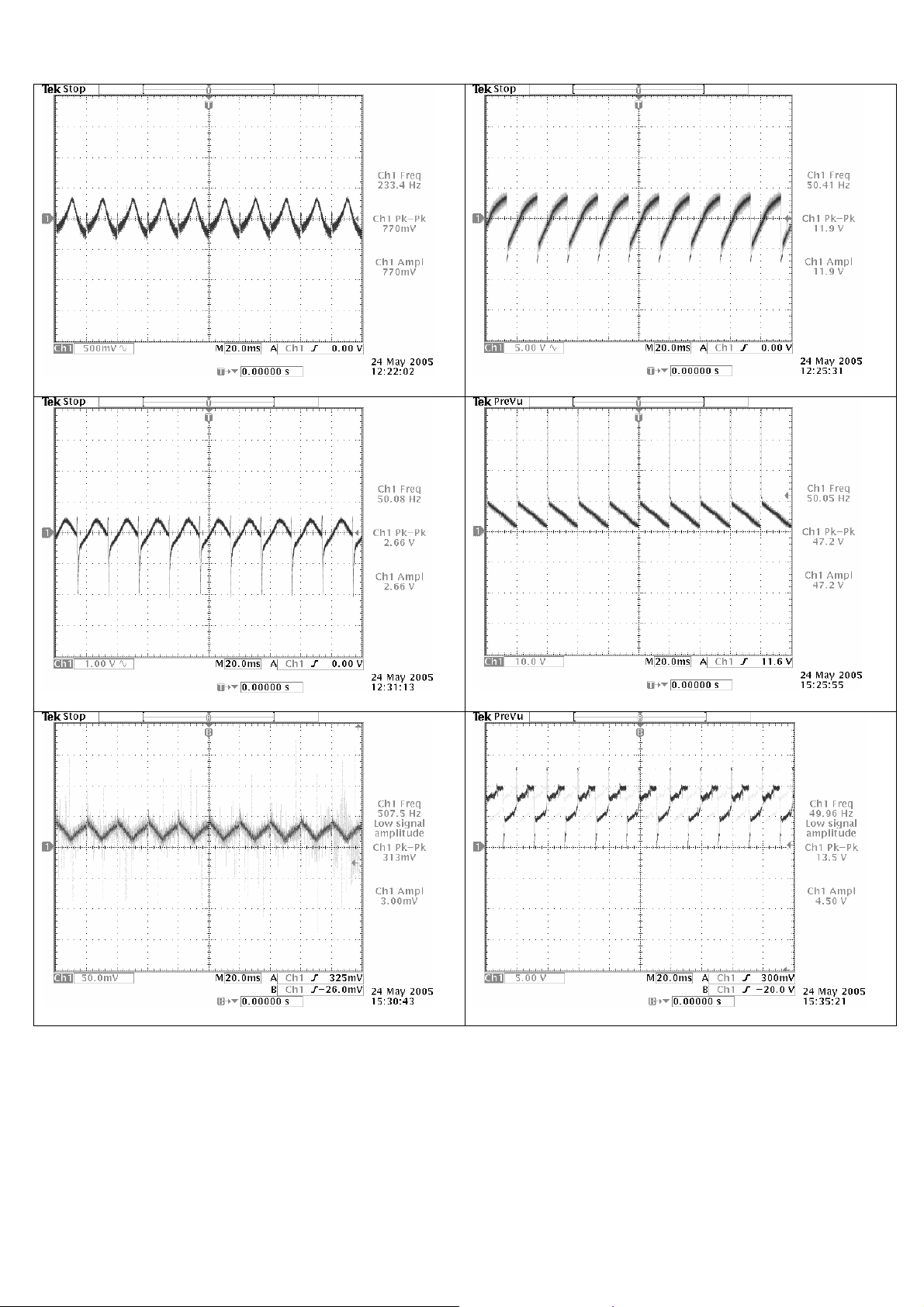
Pin 3, Supply Voltage, 15625 kHz
Pin 4, Output B, 15625 kHz
Pin 6, Flyback Supply Voltage, 15625 kHz
Pin 8, Guard Output, 15625 kHz
Pin 7, Output A, 15625 kHz
Pin 9, Feedback Input, 15625 kHz
34
Page 36

10. ELECTRICAL ADJUSTMENTS .
1. ELECTRICAL ADJUSTMENTS
1.1 Supply Voltage Adjustment
Connect a digital voltmeter to the cathode of diode D610 at the AV mode of the TV and set the screen voltage
to the minimum with the screen potentiometer. Adjust the main supply voltage (B+) with P601 potentiometer to
the following value (after supply adjustment, readjust Screen and focus voltage).
21” : 122 VDC (for A51QDX993X030)
2. SERVICE ADJUSTMENTS
To enter the Service Mode, ‘Service In/Out” button on the Service Remote Control or activate the “Picture Menu”
with the user remote control and press “9301” (Press “0” button to exit the Service Mode). To exit from the
service menu, TV/TX button should be typed on the Remote Control.
While the service menu is on screen, version and the date of the software are written on right bottom of the
screen.
For Example:
SK5.256-01 T09
12:07:26
10/03/05 F1
2.1 AGC Adjustment
• Switch to Service Menu
• Find the “AGC METHOD” under “OPTIONS” sub-menu with P+/P-,
• Set its value to “SYNC+PEAK WHITE”.
• Find “AGC” under “IF ADJ.” sub-menu with P+/P-,
• Set its value to “4”
• Find “AGC FOR VHF I” under “IF ADJ.” sub-menu with P+/P-,
• Set its value to “4”
• Set “PIP AGC” topic‘s value to “15”
• Set “PIP AGC FOR VHF I” topic‘s value to “20”
• Exit from the service menu.
2.2 Screen Adjustment
• Switch the TV to the AV mode
• Do not make any connecttion from the scart switch
• Switch on the service menu
• Set the value of “BLUEBLACK” option to “OFF”
• Set the value of the “SCREEN ADJ.” to the indicated value in FACTORY SETTINGS TABLE
• Press “OK” button on the RC
• There should appear a horizontal line on the center of the set
• Adjsut the screen potentiometre to set the line at the first seen point.
• Exit from the service menu
35
Page 37

2.3 White Balance Adjustment
• Apply a white pattern with a pattern generator to the antenna input.
• Enter the Service Menu and access to VIDEO ADJ. I sub-menu
• Set the value of “G.CUT OFF” value to “156” and “G.DRIVE” value to “356”.
• Adjust red drive with“R.DRIVE” and blue drive with “B.DRIVE” .
• Adjust red cut off with “R.CUT OFF” and blue cut off with “B. CUT OFF”
• If white balance can not be adjusted properly, slightly change the values of “G.CUT OFF” and “G.DRIVE”.
• Exit from Service menu.
2.4 Geometry Adjustments
• Apply the cross hatch pattern with a pattern generator to the antenna input.
• Enter Service Menu and access to GEOMETRY sub-menu
• The options, “50Hz GEOM.”, “50Hz. GEOM.HOR.II”, “50Hz GEOM.EHT” are for PAL/SECAM.
• The options, “60Hz GEOM.”, “60Hz. GEOM.HOR.II”, “60Hz GEOM.EHT” are for NTSC.
• Adjust Vertical Amplitude with “VERTICAL AMPLITUDE” option.
• Adjust vertical centring with “VERTICAL SHIFT”, vertical linearity with “LINEARITY” , vertical s-correction with
“S-CORRECTION”, vertical parallelogram with “VERTICAL ANGLE”, vertical bow with “VERTICAL BOW”,
horizontal centering with “HORIZONTAL SHIFT”, trapeze adjustment with “TRAPEEZE CORR.I”, general
parabole adjustment with “CUSHION CORR.I” options.
• Adjust the parabole of the top corners with “UPPER CORNER 1” and “UPPER CORNER 2”.
• Adjust the parabole of the bottom corners with “LOWER CORNER 1” and “LOWER CORNER 2”.
• Adjust the horizontal OSD centering with “HORIZONTAL OSD POSITION” and vertical OSD centering with
“VERTICAL OSD POSITION”
• For NTSC adjustments, connect an NTSC signal from AV1 follow the adjustments explained above under
the sub-menus “60Hz GEOM.”, “60Hz. GEOM.HOR.II”, “60Hz GEOM.EHT”.
• Exit from the Service Menu.
2.7 Options Menu
Enter the Service Menu with the Service RC and and access to OPTION sub-menu and the options and their
defitinons are written below.
AV1YUV : AVAILABLE(Component input is available from Scart 1); N/A(Not Available)
AV2&AV3 : AV2&AV3 N/A (Not Available); AV2 AVAIL.-AV3 N/A (AV1 Available, AV2 Not Av.);
AV2&AV3 AVAILABLE ( Both Available)
AV4 : NONE(No Front AV); CVBS+SVHS(Both Available); CVBS ONLY(Front AV Available);
SVHS ONLY(SVHS available)
TELETEXT : DEFAULT(Teletext); FASTEXT; TOPTEXT; FASTEXT+TOPTEXT
LANGUAGE : 1 (English, French, German, Italien, Spanish, Portuguese, Dutch, Greek, Danish, Swedish,
Finnish, Norwegian, Turkish, Hebrew, Russian, Hungarian, Slovak, Czech, Polish, Albanian,
Macedonian, Serbian, Slovenian, Romanian, Croatia, Bulgarian);
2 (English, French, German, Italian, Dutch, Greek, Danish, Swedish, Spanish, Portuguese,
Norwegian, Finnish, Albanian, Macedonian, Turkish, Russian, Hebrew, Hungarian, Croatia,
Romanian, Bulgarian, Slovenian, Czech, Slovak, Arabish, Persian)
TXT TABLE : AUTO; WEST(English, French, German, Turkish, Spanish, Italian, Finnish, Swedish, Norwegian,
Danish); EAST(Polish, French, Hungarian, Czech, German, Slovenian, Italian, Romanian);
GREEC(English, French, Turkish, German, Finnish, Norwegian, Swedish, Danish, Spanish, Italian,
Greek); CYRILLIC(English, Russian, German, Czech, Estonian, Ukrainian, Latvian); ARABIC(English,
French, German, Turkish, Spanish, Italian, Finnish, Swedish, Norwegian, Danish, Arabic);
FARSI(English, French, German, Turkish, Spanish, Italian, Finnish, Swedish, Norwegian, Danish,
Persian); HEBREW(English, French, German, Tuskish, Italian, Finnish, Swedish; Norwegian,Danish)
CRT : 4:3; 16:9
PIP : AVAILABLE; N/A
MAIN TUNER : Philips; Panasonic DB2G3-DA5G3; Temic; Panasonic D44G3; Sharp or Alps
PIP TUNER : Philips; Panasonic DB2G3-DA5G3; Temic; Panasonic D44G3; Sharp or Alps
SVM&DCI : ON; OFF; MENU
36
Page 38

BLUEBLACK : ON(blueblack acticated), OFF(Blueblack inactivated)
LTI&COMB : ON; OFF
CTI :ON(Colour Transition Improvement available); OFF(N/A)
ADAPTIVE PKG : ON(Digital Noise Reduction available); OFF(N/A); MENU(via menu)
PROTECTION : N/A(No Protection circuit); BCL ONLY(Only Beem Current Limiting available); VERTICAL ONLY(
Only Vertical protection avaliable); BCL&VERTICAL(Both avaliable)
PANORAMA : AVAILABLE; N/A
KEYBOARD : P-P+V-V+; MENU P/V-+
GAME : AVAILABLE; N/A
ALARM TIMER : AVAILABLE; N/A
DVD LANG : A; B; C; D
DEMO : 0(Otoprogram in first start, closed); 1(open)
2.7 Sound Options Menu
BG : EUROPE(BG Europe); NEW ZELLAND(BG New Zelland); AUSTRALIA(BG Australia); N/A(BG not
avaliable)
DK : AVAILABLE; N/A
I : AVAILABLE; N/A
L/L’ : AVAILABLE; N/A
FM RADIO
/ TV GUIDE : NONE(Radio&EPG, not available); FM RADIO(Only radio avaliable); TV GUIDE(Only TV Guide
avaliable)
NICAM : AVAILABLE; N/A
DOLBY VITUAL : AVAILABLE; N/A
BASS OPTION : DYNAMIC BASS(Dynamic Bass avaliable); SUBWOOFER(Subwoofer avaliable); NONE
HEADPHONE : AVAILABLE; N/A
CARRIER MUTE : VIA MSP; VIA MICRO
PAT : AVAILABLE(Picture and Text avaliable); N/A
SIMPLE HOTEL : AVAILABLE; N/A
HOTEL MAX
VOL : Limites the max volume level in hotel mode
AGC METHOD : SYNC PEAK WHITE; FIXED
TILT : N/A; AVAILABLE
CRT 4:3,
MODE 16:9 : VIA FLYBL(Prevents cut off line to be seen by shifting up); DISABLE CUTOFF( Directly Prevents Cut
off line to be seen)
2.7 Hotel Mode
If “Simple Hotel” option in the Service Menu is selected as “ON”, to access set up menu “4658” should be typed
whilst the “Features Menu” is on screen. After finishing the adjustments by taking the TV to St.by or shutting down,
the access can be re-inhibited.
37
Page 39
2.7 Factory Settings for Service Mode
Values given in Table 1 are typical values and can vary according to the CRT type.
FACTORY SETTINGS FOR SERVICE MODE
VIDEO ADJ. I
R.DRIVE 356 356 356 356 VERTICAL AMPLITUDE -250 -250 -170 -105
G.DRIVE 356 356 356 356 VERTICAL SHIFT 2 2 2 2
B.DRIVE 356 356 356 356 LINEARITY 20 20 -12 -12
R. CUTOFF 156 156 156 156 S-CORRECTION 140 140 130 140
G. CUTOFF 156 156 156 156 VERTICAL ANGLE 0 0 0 0
B. CUTOFF 156 156 156 156 VERTICAL BOW 0 0 0 0
IBRM 270 270 290 280 START LINE MEASUR. 11 11 14 11
WDRM 290 290 240 250 VER. BLANKING STOP 20 20 22 20
SCREEN ADJ. 296 296 250 405 VER. BLANKING START 333 333 -34 333
VIDEO ADJ. II HORIZONTAL WIDTH 0 0 0 0
BCL GAIN 270 270 270 330 HORIZONTAL SHIFT -23 -23 -23 -39
BCL TRESHOLD 200 200 200 160 TRAPEZE CORR. I 0 0 0 0
BCL TRESHOLD II 130 130 80 74 CUSHION CORR. I 0 0 0 0
BCL TIME CONSTANT 1 511 511 511 511 UPPER CORNER 1 I 0 0 0 0
BCL TIME CONSTANT 2 0 0 0 0 LOWER CORNER 1 I 0 0 0 0
OSD BRIGHTNESS 120 110 120 120 UPPER CORNER 2 I 0 0 0 0
OSD CONTRAST 140 140 110 120 LOWER CORNER 2 I 0 0 0 0
TXT BRIGHTNESS 110 90 110 110 HOR. BLANKING STOP 215 215 215 215
TXT CONTRAST 110 110 110 110 HOR. BLANKING START 1235 1235 1235 1235
YC DELAY FOR PAL 9 9 9 9 HOR. OSD POSITION 31 31 31 31
YC DELAY FOR SECAM 2 2 2 2 VER. OSD POSITION 18 18 18 18
YC DELAY FOR NTSC 10 10 10 10 60 HZ GEOM.
SUBCARRIER ADJ. 18 18 18 18 VERTICAL AMPLITUDE -206 -206 -180 -130
VIDEO ADJ. III VERTICAL SHIFT 9 9 4 5
DPWL GAIN -300 -300 -300 -300 LINEARITY 0 0 -50 -70
DPWL START P. 400 400 400 400 S-CORRECTION -41 -41 100 140
PWL TIME CONSTANT 1 1 1 1 VERTICAL ANGLE 0 0 0 0
PWL 90 90 70 90 VERTICAL BOW 0 0 0 0
SVM GAIN 0 0 0 0 START LINE MEASUR. 11 11 16 11
SVM CORING 0 0 0 0 VER. BLANKING STOP 18 18 18 18
SVM LIMITTER 0 0 0 0 VER. BLANKING START 333 333 333 333
SVM DELAY 0 0 0 0 HORIZONTAL WIDTH 0 0 0 -57
SVM DIFF. WINDOW 0 0 0 0 HORIZONTAL SHIFT -42 -42 -50 -42
PIP POSITION TRAPEZE CORR. I 0 0 0 0
HORIZONTAL CUSHION CORR. I 0 0 0 0
VERTICAL UPPER CORNER 1 I 0 0 0 0
SOUND OPTIONS LOWER CORNER 1 I 0 0 0 0
BCL DELTA 50 50 20 50 UPPER CORNER 2 I 0 0 0 0
TILT 0 0 0 0 LOWER CORNER 2 I 0 0 0 0
50HZ GEOM. EHT HOR. BLANKING STOP 190 175 175 183
EHT TRESHOLD 70 70 70 70 HOR. BLANKING START 1225 1225 1225 1225
EHT TIME CONSTANT 40 40 40 40 HOR. OSD POSITION 18 18 16 18
VERTICAL EHT 1 -162 -162 -130 -200 VER. OSD POSITION 6 6 10 9
VERTICAL EHT 2 -160 -160 -50 -40 50 HZ GEOM. HOR. II
HORIZONTAL EHT 1 0 0 0 0 HOR. WIDTH II 110 110 110 110
HORIZONTAL EHT 2 0 0 0 0 VER. ZOOM II 60 60 50 60
EHT DTC 0 0 0 0 FLYBL 14 14 17 14
EHT P1 0 0 0 0 TRAPEZE CORR. II 0 0 0 0
EHT P2 0 0 0 0 CUSHION CORR. II 0 0 0 0
60 HZ GEOM. EHT UPPER CORNER 1 II 0 0 0 0
EHT TRESHOLD 80 80 80 80 LOWER CORNER 1 II 0 0 0 0
EHT TIME CONSTANT 40 40 40 40 UPPER CORNER 2 II 0 0 0 0
VERTICAL EHT 1 -93 -93 -130 -180 LOWER CORNER 2 II 0 0 0 0
VERTICAL EHT 2 -80 -80 -40 -40 60 HZ GEOM. HOR. II
HORIZONTAL EHT 1 0 0 0 0 HOR. WIDTH II 110 110 110 110
HORIZONTAL EHT 2 0 0 0 0 VER. ZOOM II 60 60 60 60
EHT DTC 0 0 0 0 FLYBL 10 10 10 10
EHT P1 0 0 0 0 TRAPEZE CORR. II 0 0 0 0
EHT P2 0 0 0 0 CUSHION CORR. II 0 0 0 0
UPPER CORNER 1 II 0 0 0 0
LOWER CORNER 1 II 0 0 0 0
LOWER CORNER 2 II 0 0 0 0
21"
Master
UPPER CORNER 2 II 0 0 0 0
21"
Grun.
21"
GS9
21"
VC0 50 HZ GEOM.
21"
Master
21"
Grun.
21"
GS9
21"
VC0
38
Page 40
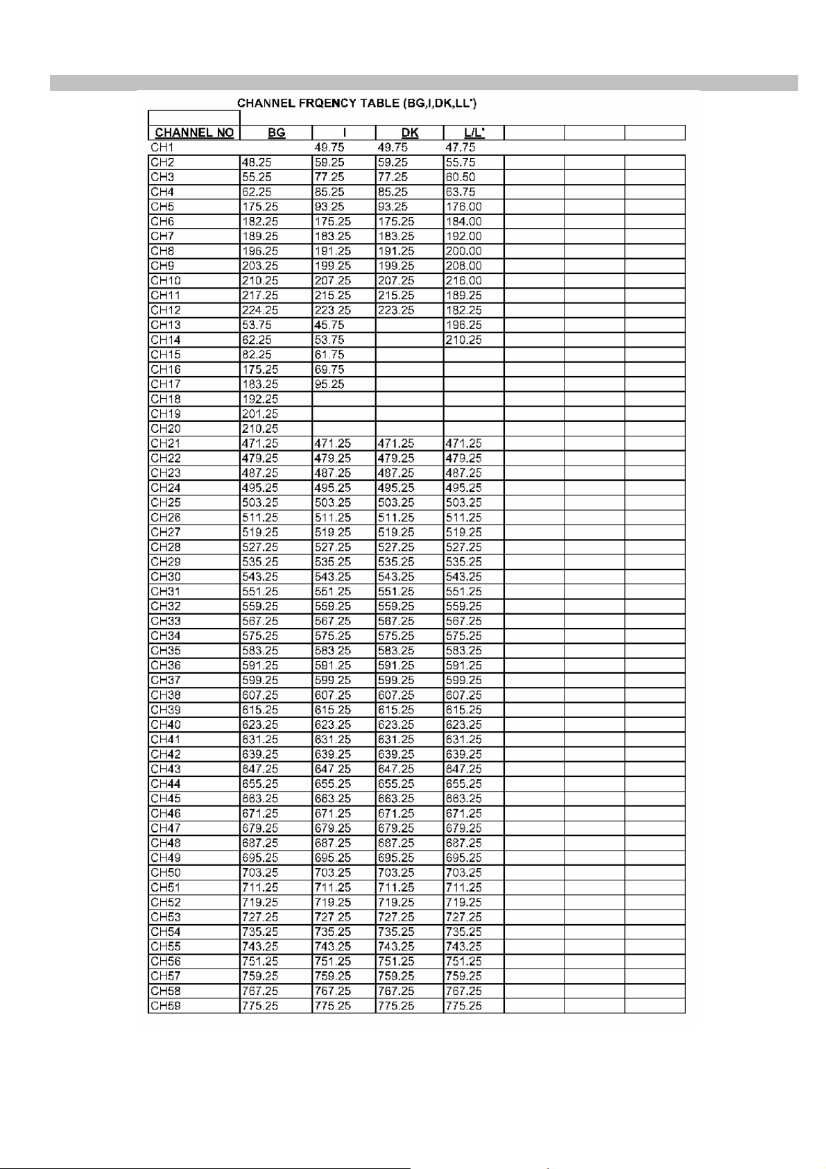
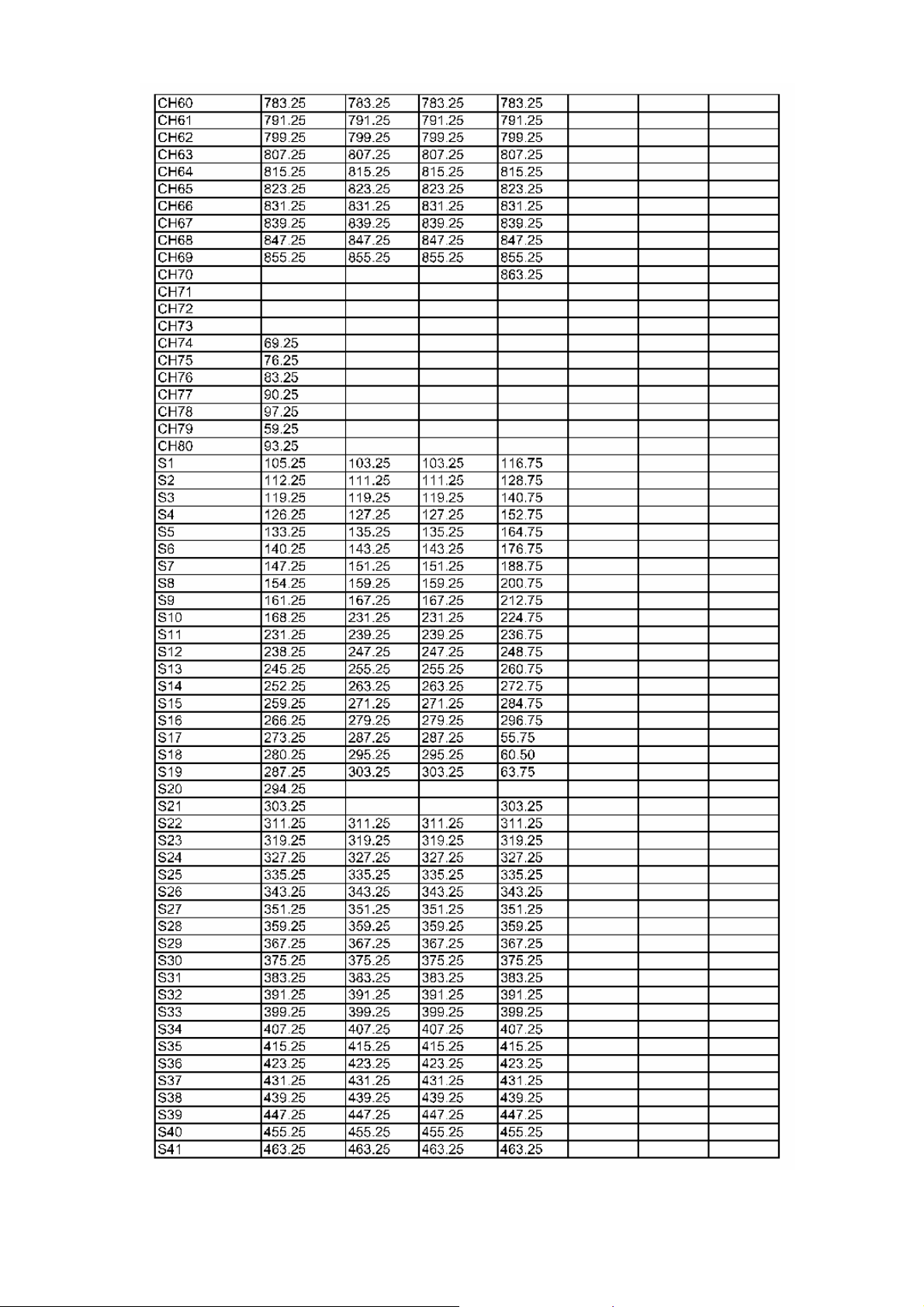
11. CHANNEL FREQUENCY TABLE .
39
Page 41
40
Page 42
R
R
R
R
R
R
R
R
R
R
R
R
R
R
R
R
R
R
R
R
R
R
R
R
R
R
R
R
R
R
R
R
R
R
R
R
R
R
R
R
R
R
R
R
R
R
R
R
R
R
R
R
R
R
R
R
R
R
R
R
R
R
R
R
R
R
R
R
R
R
R
R
R
R
R
R
R
R
R
R
R
R
R
R
R
R
R
R
R
R
R
R
R
R
R
R
R
R
R
R
R
R
R
R
R
R
R
R
R
R
R
R
R
R
R
R
R
R
R
R
R
R
R
R
R
R
V
R
R
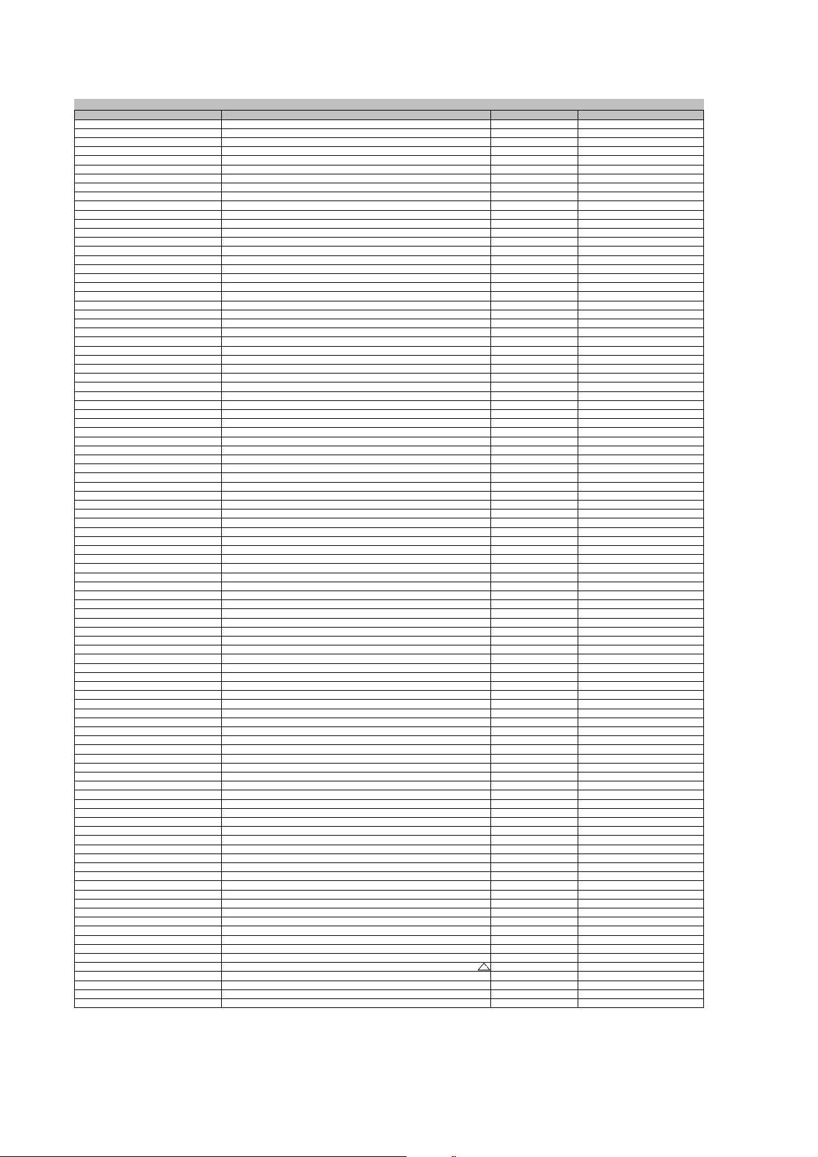
12. SPARE PARTS LIST
C01 EC 47UF M 6.3V 11*5 R:5 251487
C02-C03 CC-CHIP 100PF J 50V /1206 NPO 291101
C102 EC 47UF 16V 11*5 R:5 251478
C103 CC-CHIP 10NF K 50V /0603 X7
C104-C110 CC-CHIP 1NF K 50V /0603 X7
C111-C123 CC-CHIP 100NF K 50V /0603 X7
C125-C128 CC-CHIP 100NF K 50V /0603 X7
C129-C135 EC 3.3UF 16V 11*5 R:5 250333
C136-C146 CC-CHIP 47PF J 50V /0603 NPO TAPE 290475
C148-C151 CC-CHIP 47PF J 50V /0603 NPO TAPE 290475
C152-C155 CC-CHIP 22PF J 50V /0603 NPO TAPE 290223
C156-C157 CC-CHIP 100PF J 50V /0603 NPO 291104
C158 CC-CHIP 27NF J 25V /0603 X7
C160 EC 4.7UF 63V 11*5 R:5 250475
C161 CC-CHIP 1UF K 16V /0805 X7
C162-C163 CC-CHIP 1NF K 50V /0603 X7
C202-C210 EC 4.7UF 16V 11*5 R:5 250470
C211-C212 CC-CHIP 220PF J 50V /0603 NPO TAPE 291226
C215-C216 CC-CHIP 22NF K 50V/0603 X7R TAPE 293234
C218-C219 CC-CHIP 22NF K 50V/0603 X7R TAPE 293234
C220-C225 CC-CHIP 220PF J 50V /0603 NPO TAPE 291226
C228-C230 EC 47UF 16V 11*5 R:5 251478
C233-C235 CC-CHIP 10NF K 50V /0603 X7
C236-C241 CC-CHIP 4.7NF K 50V /0603 X7
C242 EC 47UF 16V 11*5 R:5 251478
C243 CC-CHIP 10NF K 50V /0805 X7
C247-C248 CC-CHIP 1NF K 50V /0603 X7
C249 EC 10UF 16V 5*3.5 R:5 251105
C250 CC-CHIP 220NF K 50V /0805 X7
C251 CC-CHIP 10NF K 50V /0603 X7
C252-C253 CC-CHIP 100PF J 50V /0603 NPO 291104
C301 CC-CHIP 10NF K 50V /0603 X7
C302 CC 1NF K 63V NPO R:5 202109
C304-C307 CC-CHIP 1NF K 50V /0603 X7
C308 EC 10UF 16V 5*3.5 R:5 251105
C309-C310 CC-CHIP 100NF K 50V /0603 X7
C311-C313 EC 100UF 16V 11*6 R:5 252112
C315 CC-CHIP 47NF K 25V /0603 X7R TAPE 293478
C316-C317 CC-CHIP 470NF K 16V /0805 X7
C318-C321 CC-CHIP 1NF K 50V /0603 X7
C322 EC 100UF 25V 11*6 R:5 252113
C323-C324 CC-CHIP 1.5NF K 50V /0603 X7R TAPE 292153
C325 CC-CHIP 68NF K 50V /0603 X7
C326 EC 1500UF 35V 20*13 R:5 253155
C327-C328 EC 1000UF 16V 20*10 R:5 253115
C329-C330 C-PEM 100NF J 100V R:5 274107
C331 C-CE 100NF 50V K R:5 224112
C401 EC 4.7UF 16V 11*5 R:5 250470
C402 CC-CHIP 22NF K 50V/0603 X7R TAPE 293234
C404-C405 CC-CHIP 10NF K 50V /0603 X7
C406-C407 CC-CHIP 33NF K 50V /0603 X7
C408-C410 CC-CHIP 10NF K 50V /0603 X7
C412-C421 CC-CHIP 1NF K 50V /0603 X7
C422-C424 EC 10UF 16V 5*3.5 R:5 251105
C426 CC-CHIP 100NF K 50V /0603 X7
C428 CC-CHIP 100NF K 50V /0603 X7
C429-C431 EC 100UF 16V 11*6 R:5 252112
C435-C437 CC-CHIP 330PF J 50V /0603 NPO 291337
C438 CC-CHIP 47NF K 25V /0603 X7R TAPE 293478
C441 CC-CHIP 100PF J 50V /0603 NPO 291104
C442 CC-CHIP 33PF J 50V /0603 NPO TAPE 290335
C445-C446 CC-CHIP 10PF J 50V /0603 NPO TAPE 290107
C447 CC-CHIP 220NF Z 16V /0603 Y5V TAPE 294235
C502 CC 470PF K 500V Y5P R:5 201470
C503 CC-CHIP 100NF K 50V /0603 X7
C504 CC-CHIP 47NF K 25V /0603 X7R TAPE 293478
C506-C507 CC-CHIP 10NF K 50V /0603 X7
C508-C509 CC-CHIP 100NF K 50V /0805 X7
C510 C-PEM 1NF J 100V R:5 272110
C511 C-PEM 47NF K 63V R:5 273471
C512 EC 47UF 25V 11*5 R:5 251479
C514 CC-CHIP 1NF K 50V /0603 X7
C515 EC 4.7UF 50V 11*5 R:5 250479
C517 CC 10NF K 50V R:5 203106
C518 C-PEM 220NF J 100V R:5 274230
C519 CC 68PF J 500V NPO R:5 200680
C52 EC 47UF 16V 11*5 R:5 251478
C522 C-PEM 330NF J 250V R:15 274330
C527 C-PPM 7.8NF %3.5 1.5/1.6KV R:15 CLASS-B 272780
C528 C-PPM 270NF J 250V R:15 274274
C530 EC 1UF 160V 11*6.3 R:5 250100
C531 EC 47UF 63V 11*6.3 R:5 251475
C532 EC 22UF 250V 20*13 R:5 251230
C533 EC 470UF 16V 12.5*10 R:5 252482
C534 EC 22UF-M 50V 11*5 R:5 251221
C602 CC-CHIP 47NF K 25V /0603 X7R TAPE 293478
C603-C607 CC-CHIP 10NF K 50V /0603 X7
C608 EC 10UF 63V 11*5 R:5 251116
C611 CC-CHIP 33NF K 50V /0603 X7
C612-C621 CC-CHIP 47NF K 25V /0603 X7R TAPE 293478
C622 EC 1500UF 35V 20*13 R:5 253155
C623 CC-CHIP 100NF K 50V /0603 X7
C624 C-PEM 100NF J 250V R:10 274105
C625 C-PPM 330NF K 275V-AC R:22.5 CLASS-B 274342
C626 C-PEM 220NF K 275V-AC R:15 CLASS-B 274238
C627 C-PPM 33NF J 630V R:15 203330
C628-C629 CC 470PF 2K
C630-C631 EC 47UF 160V 21*13 R:5 251489
Insertion Point Object description Component Definition
293113
292114
294122
294122
293271
295110
292114
293113
292475
293108
292114
294233
293113
293113
292114
294122
294476
292114
293685
293113
293334
293113
292114
294122
294122
294122
293113
294109
292114
293113
293334
294122
201471
See the "CPT Difference List", too
See the "CPT Difference List", too
41
Page 43
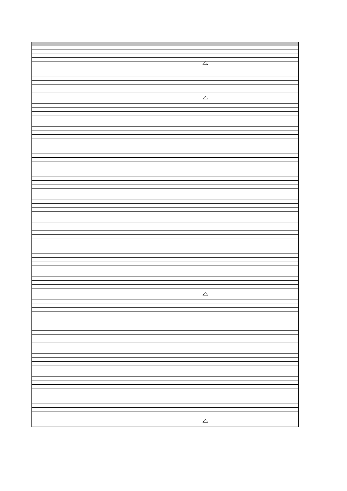
C632 CC-CHIP 56PF J 50V/0603 NPO TAPE 290562
R
R
R
R
A
R
R
R
R
R
R
R
R
R
R
R
A
R
R
R
R
R
R
R
R
R
R
R
R
R
R
R
R
R
R
R
R
R
R
R
C
R
R
C
R
R
C
R
R
C
R
R
C
R
7
R
R
C
R
R
R
R
R
R
R
R
C
R
R
C
R
R
R
R
R
R
R
R
R
R
R
R
R
L
R
R
R
8
R
R
R
R
R
R
R
R
R
R
R
R
R
R
R
R
5
R
5
R
R
R
R
R
R
R
R
C633 CC-CHIP 680PF J 0603 50V NPO 291688
C634 C-PEM 100NF J 250V R:10 274105
C635 CC-CHIP 1.5NF K 50V /0603 X7R TAPE 292153
C636-C637 CC 220PF M 250VAC R:10 Y5U AH/NS
C639-C642 CC 1NF K 1KV Y5P R:5 202105
C644 C-PEM 100NF J 250V R:10 274105
C646 CC-CHIP 100NF K 50V /0805 X7
C647-C649 CC-CHIP 10NF K 50V /0603 X7
C650 CC-CHIP 47PF J 50V /0603 NPO TAPE 290475
C651 EC 100UF 400V 30*22 R:10 252121
C652 EC 47UF 25V 11*5 R:5 251479
C653 CC 220PF K 2KV Y5P R:5 201226
C654 CC 2.2NF M 250VAC Y5U R:10 AH/NS
C655 C-ELA 2200UF 16V 20*13 R:5 253233
C656 EC 1000UF 16V 20*10 R:5 253115
C657 CC-CHIP 56PF J 50V/0603 NPO TAPE 290562
C658 EC 1000UF 16V 20*10 R:5 253115
C659 EC 47UF 25V 11*5 R:5 251479
C660 EC 1000UF 16V 20*10 R:5 253115
C661 CC 100PF 500V NPO R:5 201108
C662 EC 1000UF 16V 20*10 R:5 253115
C664-C667 EC 22UF 16V 11*5 R:5 251225
C668 EC 22UF 25V 11*5 R:5 251226
C670 EC 1000UF 16V 20*10 R:5 253115
C701 EC 10UF 16V 5*3.5 R:5 251105
C702 CC-CHIP 100NF K 50V /0603 X7
C704-C705 EC 10UF 250V 16*10 R:5 251109
C706-C708 CC-CHIP 680PF J 0603 50V NPO 291688
C709 CC-CHIP 10PF J 50V /0603 NPO TAPE 290107
C710-C712 CC 390PF J 50V SL R:5 201390
C713 CC 4.7NF K 1KV Z4V R:7.5 222477
C714 C-PEM 100NF J 250V R:10 274105
C920-C923 CC 1NF K 50V Y5P R:5 202106
C940-C941 C-PEM 47NF K 63V R:5 273471
D01 LED IR SIR563SB3F 23/940 303991
D102 DIODE 1N5819 SHOTH 303246
D201 DIODE 4148 MELF SOD-80
D202 DIODE 1N4148 52MM 302289
D401-D405 DIODE 4148 MELF SOD-80
D501 DIODE 1N4148 52MM 302289
D504-D505 DIODE 4148 MELF SOD-80
D508-D511 DIODE BA157 300311
D512 DIODE 4148 MELF SOD-80
D604 DIODE 1N4148 52MM 302289
D605 DIODE 4148 MELF SOD-80
D606-D609 DIODE RF200
D610 DIODE RGP30MS 303206
D611 DIODE 4148 MELF SOD-80
D612-D613 DIODE 1N4148 52MM 302289
D614 DIODE RGP10J 303217
D615 DIODE RGP30D 303228
D616 DIODE SB540 303424
D617-D618 DIODE RGP10J 303217
D619 DIODE BA157 300311
D620 DIODE 1N4148 52MM 302289
D621-D701 DIODE 4148 MELF SOD-80
D702-D704 DIODE 1N4148 52MM 302289
D705-D707 DIODE 4148 MELF SOD-80
D708 DIODE 1N4007 302948
DOWN TACT SWITCH 2 LEG (MTSB) 010844
EJECT TACT SWITCH 2 LEG (MTSB) 010844
F103 SAW FILTER X6966M 056298
FORWARD TACT SWITCH 2 LEG (MTSB) 010844
FS601 FUSE 3.15AT (215) 054280
IC01 IC-CHIP S3C1840DA9/SMB91 T&
IC101 IC VCTI-ECO-90DEG.-NO VD-FLASH-F1 453987
IC201 IC-CHIP MC14052BDR2 G T&
IC301 IC AN5277 453170
IC401 IC-CHIP AT24C16AN 10SU2.7 TAPE&REE
IC501 IC TDA8357 J N2 452975R-1
IC601 IC MC33269T G 0.8A LD TO220 453177
IC602 IC ICE1QS01 452785
IC603-IC604 IC LM317LZRAG 0.1A TO92 453176
IC605 IC TL431CLPRA G 451885R-1
IC606-IC60
IC609 IC TL431CLPRA G 451885R-1
L101-L102 COIL CHOKE 10UH LAN02 280MA/1
L103 COIL 10UH LAL02 053331
L104-L105 COIL 10UH K (TAIYO) LAL03 053711
L106 COIL 10UH LAL02 053331
L107-L108 COIL CHOKE 10UH LAN02 280MA/1
L109-L110 COIL 10UH K (TAIYO) LAL03 053711
L111 COIL 10UH K AXIAL LAL04 053500
L112 COIL CHOKE 10UH LAN02 280MA/1
L113 COIL 4.7UH LAL03 053734
L114 COIL 4.7UH LAL04 52MM 053732
L115 COIL-CHIP 8.2UH K /0805 053806
L116-L117 COIL 10UH LAL02 053331
L203-L204 COIL-CHIP 10UH K 080
L207-L208 COIL-CHIP 10UH K 080
L301 COIL 10UH K (TAIYO) LAL03 053711
L401-L403 COIL CHOKE 10UH LAN02 280MA/1
L404 COIL 10UH K (TAIYO) LAL03 053711
L405 COIL CHOKE 10UH LAN02 280MA/1
L406 COIL 4.7UH LAL03 053734
L504 COIL H-LIN 100UH 51600
L601 LINE FILTRE 2*18MH R<0.7R /2416008010122 51828
L602 COIL CHOKE 50UH DIALTECH 053739R-10
Insertion Point Object description Component Definition
201227
294109
293113
202220
294122
303195
303195
303195
303195
303195
303308
303195
303195
303195
452382
453174
452662R-2
IC-CHIP NCP1117DTARK G (DPAK) T&R TO252 453095
053823
053823
053823
053804
053804
053823
053823
See the "CPT Difference List", too
42
Page 44
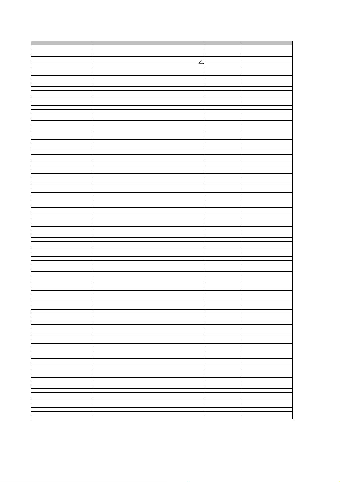
L603 COIL 4.7UH LAL03 053734
R
R
R
R
Y
R
R
R
R
R
R
R
R
R
R
R
R
R
R
R
R
R
R
R
R
R
R
R
R
R
R
R
R
R
R
R
R
R
R
R
R
R
R
R
R
R
R
R
R
R
R
R
R
R
R
R
R
R
R
R
R
R
R
R
R
R
R
R
R
R
R
R
R
R
R
R
R
R
R
R
R
R
R
R
R
R
R
R
R
R
R
R
R
R
R
R
L701 COIL- CHOKE 10UH R0814 14.1 053352
MENU TACT SWITCH 2 LEG (MTSB) 010844
P602 R-VAR 10K V(2.5MM) 5*3 133118
PH601 IC OPTOCOUPLER TCET1100/V310U27 VISHA
PLAY/PAUSE TACT SWITCH 2 LEG (MTSB) 010844
PR/VOL TACT SWITCH 2 LEG (MTSB) 010844
Q01 CER.RESONATOR GSB455E 056210
Q102 CRYSTAL 20.25MHZ 20PPM (106478) 056038
R01 RC-CHIP 0R /1206 179002
R102-R108 RC-CHIP 10K J 1/16W /0603 173108
R109-R110 RC-CHIP 100R J 1/16W /0603 171107
R113-R115 RC-CHIP 100R J 1/16W /0603 171107
R119 RC-CHIP 33K J 1/16W /0603 TAPE 173332
R120 RC-CHIP 0R /0603 1.6*0.8 TAPE 179005
R121 RC-CHIP 1K J 1/16W /0603 172104
R122-R123 CFR 220R J 1/4W 52MM 101223
R124 RC-CHIP 6.8K J 1/16W /0603 172686
R125-R126 CFR 4.7K J 1/4W /6 26MM 102487
R127 CFR 47K J 1/4W /6 26MM 103484
R128 RC-CHIP 100R J 1/16W /0603 171107
R129 CFR 100R J 1/4W 26MM 101117
R130 RC-CHIP 100R J 1/16W /0603 171107
R131-R132 CFR 100R J 1/4W 26MM 101117
R133 RC-CHIP 0R /0805 2*1.25 179001
R201-R202 RC-CHIP 18K J 1/16W /0603 TAPE 173183
R203-R204 RC-CHIP 330R J 1/16W /0603 TAPE 171336
R205-R206 RC-CHIP 560R J 1/16W/0603 TAPE 171562
R207-R209 RC-CHIP 470R J 1/16W /0603 TAPE 171472
R210 CFR 10K J 1/4W /6 52MM 103116
R211 RC-CHIP 0R /0603 1.6*0.8 TAPE 179005
R212 RC-CHIP 180R J 1/16W /0603 171184
R213-R223 RC-CHIP 75R J 1/16W /0603 170754
R224 RC-CHIP 180R J 1/16W /0603 171184
R225-R226 RC-CHIP 100R J 1/16W /0603 171107
R228 CFR 100R J 1/4W 26MM 101117
R229 RC-CHIP 100R J 1/16W /0603 171107
R230 RC-CHIP 100R J 1/16W /0603 171107
R233-R236 RC-CHIP 270R J 1/16W/0603 TAPE 171227
R237-R257 RC-CHIP 1K J 1/16W /0603 172104
R258 CFR 4.7R J 1/4W /6 26MM 109473
R259 CFR 10K J 1/4W /6 52MM 103116
R301-R302 RC-CHIP 330R J 1/16W /0603 TAPE 171336
R303-R304 RC-CHIP 7.5K J 1/16W /0603 172751
R305-R306 RC-CHIP 10K J 1/16W /0603 173108
R307 RC-CHIP 6.8K J 1/16W /0603 172686
R308 RC-CHIP 1K J 1/10W /0805 172101
R311 CFR 1K J 1/4W /6 52MM 102101
R312-R312 RC-CHIP 3.3K J 1/16W /0603 172336
R314 RC-CHIP 2.2K J 1/16W/0603 TAPE 172224
R317-R318 RC-CHIP 56K J 1/16W /0603 173563
R319-R320 RC-CHIP 4.7K J 1/16W /0603 TAPE 172479
R323-R324 CFR 4.7R J 1/4W /6 26MM 109473
R325 RC-CHIP 18K J 1/10W /0805 173182
R401 RC-CHIP 470R J 1/16W /0603 TAPE 171472
R402 RC-CHIP 10K J 1/16W /0603 173108
R404-R407 RC-CHIP 100R J 1/16W /0603 171107
R408-R409 CFR 100R J 1/4W 26MM 101117
R410-R413 RC-CHIP 100R J 1/16W /0603 171107
R414-R417 RC-CHIP 270R J 1/16W/0603 TAPE 171227
R418 RC-CHIP 1K J 1/16W /0603 172104
R419 CFR 1K J 1/4W /6 52MM 102101
R420 CFR 10K J 1/4W /6 52MM 103116
R423-R424 RC-CHIP 2.7K J 1/16W /0603 172276
R425 RC-CHIP 22R J 1/16W /0603 TAPE 170221
R427-R431 RC-CHIP 3.3K J 1/16W /0603 172336
R432 RC-CHIP 180R J 1/16W /0603 171184
R434 RC-CHIP 22K J 1/16W /0603 173229
R435 CFR 22K J 1/4W 26MM 103234
R436-R437 RC-CHIP 7.5K J 1/16W /0603 172751
R439-R441 RC-CHIP 150R J 1/16W /0603 171154
R442-R444 RC-CHIP 33R J 1/16W /0603 TAPE 170333
R445 RC-CHIP 4.7K J 1/16W /0603 TAPE 172479
R446 RC-CHIP 100K J 1/16W /0603 173114
R447 RC-CHIP 1.5K J 1/16W /0603 TAPE 172154
R448 CFR 10K J 1/4W /6 52MM 103116
R449 RC-CHIP 4.7K J 1/16W /0603 TAPE 172479
R450 CFR 10K J 1/4W /6 52MM 103116
R451 RC-CHIP 5.6K J 1/16W /0603 TAPE 172567
R452 RC-CHIP 47K J 1/16W /0603 TAPE 173478
R453 RC-CHIP 1.2K J 1/16W/0603 TAPE 172125
R454-R460 RC-CHIP 100R J 1/16W /0603 171107
R461 RC-CHIP 4.7K J 1/16W /0603 TAPE 172479
R462 CFR 4.7K J 1/4W /6 26MM 102487
R463 RC-CHIP 220R J 1/16W/0603 TAPE 171224
R464 RC-CHIP 22R J 1/10W /0603 170225
R466-R467 RC-CHIP 1.5K J 1/16W /0603 TAPE 172154
R468 RC-CHIP 1K J 1/16W /0603 172104
R472 RC-CHIP 1.5K J 1/16W /0603 TAPE 172154
R481 RC-CHIP 15K J 1/16W /0603 TAPE 173153
R501 RC-CHIP 18K J 1/16W /0603 TAPE 173183
R502 RC-CHIP 220R J 1/16W/0603 TAPE 171224
R504 RC-CHIP 1K J 1/16W /0603 172104
R506 RM 10K J 1/2W 52MM 113114
R508 CFR 2.7K J 1/4W /6 52MM 102273
R509 RC-CHIP 5.6K J 1/10W /0805 172561
R51 CFR 390R J 1/4W /6 26MM 101396
R510 RC-CHIP 5.6K J 1/10W /0805 172561
R511 RC-CHIP 560K J 1/16W /0603 174563
Insertion Point Object description Component Definition
452297R-2
See the "CPT Difference List", too
43
Page 45
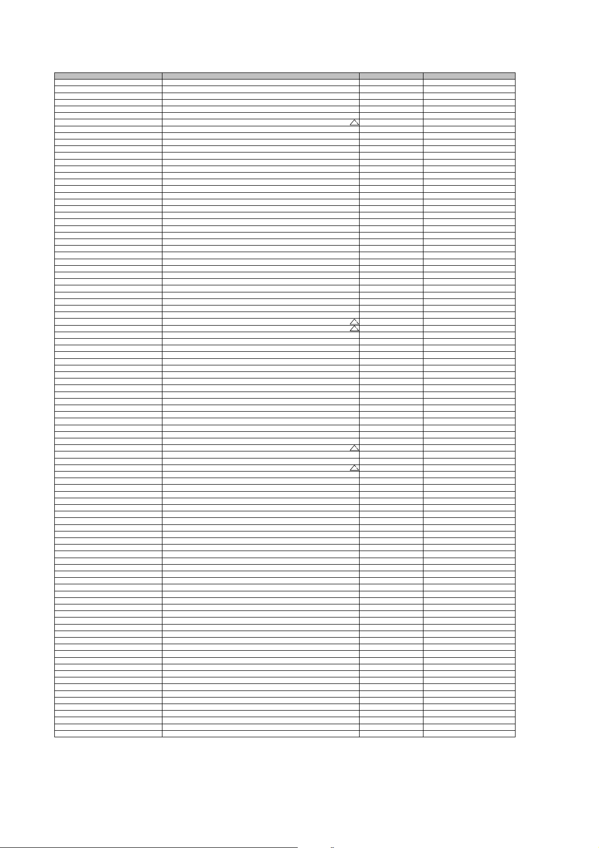
R513 RC-CHIP 10K J 1/16W /0603 173108
R
R
R
R
R
R
R
R
R
R
R
R
R
R
R
R
R
R
R
R
R
R
R
R
R
R
R
R
R
R
R
R
R
R
R
R
R
R
R
R
R
R
R
R
R
R
R
R
R
R
R
R
R
R
R
R
R
R
R
R
R
R
R
R
R
R
R
R
R
R
R
R
R
R
R
R
R
R
R
R
R
R
R
R
R
R
R
R
R
R
R
R
R
R
R
R
R
R514 RC-CHIP 10K J 1/16W /0603 173108
R515 CFR 2.7K J 1/4W /6 52MM 102273
R516-R517 RM 3.9R J 1/2W /9 52MM 111396
R52 CFR 220R J 1/4W 26MM 101236
R521 RW 4.7R J 7W R:5 129487
R522 RMF 0.22R J 1W 119224
R523 CFR 330R J 1/4W /6 52MM 101331
R524 CFR 1.5R J 1/2W /9 109150
R525 RMF 10R 1/4W 120118
R526 CFR 47K J 1/4W /6 26MM 103484
R527 CFR 470R J 1/2W /9 52MM 101471
R529 CFR 560R J 1/4W /6 52MM 101562
R531-R532 RM 150K J 1/2W ' SAFETY' 114151
R533 CFR 0.47R J 1/2W /9 52MM 109472
R534 CFR 47R J 1/4W /6 52MM 100473
R537 RC-CHIP 56R J 1/16W /0603 TAPE 170560
R538 RC-CHIP 1.5K J 1/16W /0603 TAPE 172154
R539 RC-CHIP 47K J 1/16W /0603 TAPE 173478
R54 CFR 1.5K J 1/4W /6 26MM 102166
R540 RC-CHIP 47K J 1/16W /0603 TAPE 173478
R541 RC-CHIP 10K J 1/16W /0603 173108
R542 RC-CHIP 1.5K J 1/16W /0603 TAPE 172154
R55 CFR 1K J 1/4W /6 52MM 102101
R56-R57 CFR 470R J 1/4W /6 52MM 101470
R58 CFR 390R J 1/4W /6 26MM 101396
R59 CFR 220R J 1/4W 26MM 101236
R601-R602 RC-CHIP 10K J 1/16W /0603 173108
R605 RC-CHIP 1K J 1/16W /0603 172104
R606 CFR 1K J 1/4W /6 26MM 102141
R608 RC-CHIP 390R %1 1/16W/0603 TAPE 171392
R609 RC-CHIP 1K J 1/16W /0603 172104
R610 CFR 1K J 1/4W /6 52MM 102101
R611 RC-CHIP 2.7K J 1/16W /0603 172276
R617 RC-CHIP 22K J 1/16W /0603 173229
R618 RC-CHIP 47K J 1/16W /0603 TAPE 173478
R619 RM 1M J .5W 52MM SAFETY 115110
R620 PTC 9R/2 PIN - 3 CYCLE BOX TYPE 154234
R621 RMO 68K J 2W 73MM 113684
R624 RC-CHIP 47K J 1/16W /0603 TAPE 173478
R625 RC-CHIP 3.3K J 1/16W /0603 172336
R626 RC-CHIP 22R J 1/10W /0603 170225
R627 CFR 47K J 1/4W /6 26MM 103484
R628 RM 115K %1 1/4W 114115
R629 CFR 10K J 1/4W /6 26MM 103136
R63 CFR 100R J 1/4W 26MM 101117
R631 RMO 47K J 1W 113475
R632 RC-CHIP 12K J 1/16W /0603 TAPE 173124
R634 RC-CHIP 0R /0603 1.6*0.8 TAPE 179005
R635 RW 2.7R K 5W R:15 MM 129272
R636 RM 1M J 1W 52MM 115103
R637 RC-CHIP 68K J 1/16W /0603 173685
R638 CFR 47R J 1/4W /6 52MM 100473
R639 CFR 120R J 1/4W 52MM 101124
R640 RC-CHIP 33R J 1/16W /0603 TAPE 170333
R644 RM 4.7M J 1/2W 52MM 'SAFETY ' 115470
R645 CFR 47R J 1/4W /6 52MM 100473
R648 RC-CHIP 820R J 1/16W /0603 TAPE 171824
R649 RPF 0.05R K 1/2W AXIAL 119003
R650 RC-CHIP 2.7K %1 1/16W /0603 172278
R651 RC-CHIP 39K J 1/16W /0603 TAPE 173394
R652 RM 150K J 1/2W ' SAFETY' 114151
R654 RC-CHIP 1.3K %1 1/16W/0603 TAPE 172131
R656-R658 RC-CHIP 240R %1 1/16W /0603 TAPE 171241
R659 RC-CHIP 390R %1 1/16W/0603 TAPE 171392
R660-R661 RC-CHIP 2.7K %1 1/16W /0603 172278
R663 RC-CHIP 365R %1 1/16W /0603 TAPE 171363
R664 RC-CHIP 390R %1 1/16W/0603 TAPE 171392
R665 RC-CHIP 470R %1 1/16W /0603 TAPE 171479
R666 RC-CHIP 120R %1 1/16W /0805 171128
R667 RC-CHIP 820R %1 1/16W /0603 TAPE 171825
R668 RC-CHIP 240R %1 1/16W /0603 TAPE 171241
R702-R705 RC-CHIP 1K J 1/16W /0603 172104
R706-R708 CFR 1K J 1/2W /6 52MM 102105
R709-R711 RC-CHIP 220R J 1/16W/0603 TAPE 171224
R712-R714 RC-CHIP 3.3K J 1/16W /0603 172336
R715 CFR 220R J 1/4W 26MM 101236
R716-R718 RMO 12K J 2W 113121
R719 CFR 330K J 1/4W /6 52MM 104332
R720 CFR 47K J 1/4W /6 26MM 103484
R721 CFR 1M J 1/4W /6 26MM 105110
R722-R724 RC-CHIP 22R J 1/10W /0603 170225
R725 CFR 1.5K J 1/2W /9 52MM 102159
R726-R727 CFR 100R J 1/4W 26MM 101117
R728 RC-CHIP 100R J 1/16W /0603 171107
R729 CFR 470K J 1/4W /6 26MM 104470
R730-R732 RC-CHIP 470R J 1/16W /0603 TAPE 171472
R920-R921 CFR 75R J 1/4W /6 26MM 100751
R922-R923 CFR 470R J 1/4W /6 26MM 101494
R940-R941 CFR 180R J 1/2W (A) 52MM 101184
R942-R943 CFR 390R J 1/4W /6 26MM 101396
REWIND TACT SWITCH 2 LEG (MTSB) 010844
SK202 SCART SOKET HR-DM2441S-O 31197
STOP TACT SWITCH 2 LEG (MTSB) 010844
T01 TRN BC337-25 401047
T102-T205 TRN-CHIP BC848BLT1G SOT23 401141
T206-T207 TRN-CHIP BC858BLT1G SOT23 401142
T301-T307 TRN-CHIP BC848BLT1G SOT23 401141
T401 TRN-CHIP BC818-215 SOT23 401193
Insertion Point Object description Component Definition
See the "CPT Difference List", too
See the "CPT Difference List", too
See the "CPT Difference List", too
44
Page 46
T403-T406 TRN-CHIP BC848BLT1G SOT23 401141
R
R
R
R
R
R
R
R
R
R
R
R
R
Y
R
R
R
D
K
R
Y
Y
A
R
R
R
R
R
R
R
O
R
Y
R
R
R
R
R
R
R
V
R
R
R
R
R
T407-T501 TRN-CHIP BC858BLT1G SOT23 401142
T502 TRN BC639 400240
T504 TRN. 2SD2586 401506
T505 TRN BC327-25RL1 G 400901
T506-T608 TRN-CHIP BC848BLT1G SOT23 401141
T609 TRN 2SK3567 TO220SIS 401512
T610 TRN STP20NE06LFP 401335
T701-T703 TRN-CHIP BC848BLT1G SOT23 401141
T704-T706 TRN BF421 401366
T707-T709 TRN 2SC3619 400891
TH601 THRYSTOR MCR22-8RL1G 410026
TR501 TRANSFORMER HORIZONTAL DRIVE E1 051839
TU102 TUNER PS ASIMETRIK ENV57DA5G3R(SEC LL I
TV/DVD TACT SWITCH 2 LEG (MTSB) 010844
UP TACT SWITCH 2 LEG (MTSB) 010844
X202 CON.MALE6' LI 2317-6S JST B 6B-XH-A WHIT 38874
X202-DVD CABLE 8+6'LI BEYAZ L=....K5 KX5511
X203 CONN.HOUSING X2003 RE
X204 CONN.HOUSING X2003 BLAC
X205 CONN. CINCH .......BLACK HOR. L6B 032937
X301 CONN.HOUSING X2004 GRE
X302 CONN.HOUSING X2003 GRE
X401
X402 CONN.HOUS.2P 2317-2S JST B 2B-XH-A RED 032993
X402-1 CONN.MALE 5 RIGHT-A 2317-5R JST S 5B-XH- 38889
X402-2 CONN.HOUSING.2P 2.5MM HORZ.250GX402-X402-2 CABLE HAR.CFIZ 2'LI TUS T. DVD L=...MM KX5530
X403 CONN.HOUS.3P 2317-3S JST B 3B-XH-A RED 31646
X403-DVD CABLE 3'LU 2317 BEYAZ KON.L=330 FER+SUN Y08509
X404 CONN.HOUSING 2.5TMK 2104 GRI 31989
X406 CONN.HOUS.5P 2317-5S JST B 5B-XH-A RED 031196
X406-X402-1 CABLE 5'LI RED/WHI CON.L=370 K5 KX5512
X407 CONN.HOUS.2P 2317-2S JST B 2B-XH-A WHITE 31245
X407-DVD CABLE BLEND/FER. 2'LI L=430 DIG.AUDI
X501 CONN.HOUSING 2'LI GRE
X502 CON.HOUSING LOCKED 5/4 31777
X503 CABLE WITH HOLDER 3+1P L=430 CRT/SASI K1 KX1553
X601 CON.HOUSING 2P MALE 31675
X602 CON.HOUSING 2P MALE TPK75(POW)12.6 RED 31797
X603 CON.MALE 5'LI 2317-5S JST B5B-XH-A BLACK 38890
X603-DVD CABLE 5'LI BLACK/WHI MINI KON.L=...K5 FE KX5513
X703 CRT SOCKET NARROW INCHANG 31532
X921 KONN. CINCH ........... YELLOW HOR.14.1 031165
X922 KONN. CINCH ........... RED HOR.14.1 031164
X923 KONN. CINCH ........ WHITE HOR.14.1 031163
X925 CONN.S-VHS 031795
X941 HEADPHONE JACK YKB21-5103 031423
ZD501 DIODE Z. BZX55C 15
ZD502 DIODE Z. BZX55C33 52MM 302318
ZD503-ZD504 DIODE Z. BZX55C8V2 26MM 302294
ZD601 DIODE Z.TZMB9V1 303454
ZD602 DIODE Z. BZX55C5V1 302298
TR502 DST 21PF TR/2416003313132 28KV K1 040150R-T1 See the "CPT Difference List", too
TR601 SMPS 20/21 EL/ 2084.0130 23V 050150R-E1 See the "CPT Difference List", too
Insertion Point Object description Component Definition
7RZ136RPS4
31857
31856
31858
CABLE WITH HOLDER 5P L=275 CRT/CHAS KX5558
DEGAUS BOB.KPL 21" B.SARGILI (9R PTC) 621167-AS
CPT SS A51QDX993X030 P.FLAT(MACAR) 056321-SS0
K5 CHASSIS-SD 21" P/BG/SX/2SC/K/S/A-OSD KX5110
DVD COMBO DIVX LOADER HUALU KX5001R
HOP. 8R 7W(NOM:)/10W (MAX) 120X50 7ZY107R
31854
31575
KX5504
31850
303826
See the "CPT Difference List", too
See the "CPT Difference List", too
See the "CPT Difference List", too
45
 Loading...