

Beko FLMSF53LL220, FLMSF53DL220, FLMSF53LL400, FLMSF53DL400 Installation And Operating Manual
METPOINT® FLM SF53
FLMSF53LL220 | FLMSF53DL220 | FLMSF53LL400 | FLMSF53DL400
Thermal ow meter
Installation and operating manual
EN - English
10-221

Installation and operating manual EN
2 METPOINT® SF53
Content
1. Safety information .......................................................................................................................................... 4
1.1. Pictograms and symbols .......................................................................................................................... 4
1.1.1. In this documentation ........................................................................................................................................................4
1.1.2. On the device .......................................................................................................................................................................4
1.2. Signal words according to ISO 3864 and ANSI Z.535 ................................................................................ 4
1.3. Safety instructions .................................................................................................................................. 5
1.4. Transport and storage ............................................................................................................................. 6
1.5. Intended use ........................................................................................................................................... 7
1.6. Warranty and liability ............................................................................................................................. 7
2. Product information ....................................................................................................................................... 8
2.1. Scope of delivery .................................................................................................................................... 8
2.2. Type plate ............................................................................................................................................... 8
2.3. Product overview and description ........................................................................................................... 9
2.3.1. Identication based on product code.............................................................................................................................9
2.3.2. Product description .........................................................................................................................................................10
2.3.3. Operating principle .......................................................................................................................................................... 10
2.4. Control and display elements ................................................................................................................ 11
2.4.1. Version with display .........................................................................................................................................................11
2.4.2. Version with LED .............................................................................................................................................................. 11
2.4.3. Direction of ow ............................................................................................................................................................... 12
2.5. Dimensions ........................................................................................................................................... 13
2.6. Technical data ....................................................................................................................................... 14
2.7. Measuring ranges ................................................................................................................................. 15
3. Installation ................................................................................................................................................... 17
3.1. Warning ................................................................................................................................................ 17
3.1.1. Requirements for piping ................................................................................................................................................. 17
3.1.2. Requirements for inlet/outlet sections ....................................................................................................................... 17
3.1.3. Turning housing ................................................................................................................................................................ 18
3.2. Installation ........................................................................................................................................... 19
4. Electrical installation .................................................................................................................................... 20
4.1. Pin assignment of plug-type connectors ................................................................................................ 20
4.2. Connection options ............................................................................................................................... 20
4.2.1. Bidirectional RS485 bus system .................................................................................................................................... 20
4.2.2. Current output 4 ... 20 mA, 3-wire .............................................................................................................................. 21
4.2.3. MBus....................................................................................................................................................................................21
4.2.4. Galvanically isolated pulse output ............................................................................................................................... 22
4.3. Connection of METPOINT® BDL ............................................................................................................. 23
4.3.1. Bidirectional RS485 bus system .................................................................................................................................... 23
4.3.2. Current output 4 ... 20 mA, 3-wire ............................................................................................................................... 24
4.3.3. Galvanically isolated pulse output ............................................................................................................................... 24
4.4. Connection to METPOINT® BDL compact ............................................................................................... 25
4.4.1. Bidirectional RS485 bus system .................................................................................................................................... 25
4.4.2. Current output 4 ... 20 mA, 3-wire ............................................................................................................................... 25
4.4.3. Galvanically isolated pulse output ............................................................................................................................... 26
4.5. Modbus termination ............................................................................................................................. 26

EN Installation and operating manual
3 METPOINT® SF53
5. Start-up ........................................................................................................................................................ 27
6. Conguration and operation ......................................................................................................................... 27
6.1. Display during operation ....................................................................................................................... 27
6.2. Setup menu .......................................................................................................................................... 28
6.3. Sensor Setup ......................................................................................................................................... 28
6.3.1. Entering pipe inside diameter ....................................................................................................................................... 29
6.3.2. Entering / changing consumption counter value ..................................................................................................... 29
6.3.3. Selecting units for consumption, ow, temperature and pressure ...................................................................... 30
6.3.4. Entering reference conditions ....................................................................................................................................... 31
6.3.5. Setting zero point for low-ow cut-o function ....................................................................................................... 32
6.4. Modbus setup ....................................................................................................................................... 33
6.4.1. Modbus settings (2001 ... 2005) ................................................................................................................................... 34
6.4.2. Values register (1001 …1500) ........................................................................................................................................34
6.5. Pulse / alarm ......................................................................................................................................... 35
6.5.1. Pulse output ...................................................................................................................................................................... 35
6.6. User Setup ............................................................................................................................................ 36
6.7. Advanced ............................................................................................................................................. 36
6.8. 4 ... 20 mA ............................................................................................................................................ 37
6.9. Info ...................................................................................................................................................... 38
6.10. MBus .................................................................................................................................................. 38
6.10.1. Default communication settings ................................................................................................................................ 38
6.10.2. Transferred values .......................................................................................................................................................... 38
7. Spare parts and accessories ........................................................................................................................... 39
8. Maintenance and servicing............................................................................................................................ 39
9. Cleaning sensor head .................................................................................................................................... 39
10. Calibration ................................................................................................................................................. 39
11. LED indicator .............................................................................................................................................. 39
12. Declaration of Conformity .......................................................................................................................... 40
Installation and operating manual EN
4 METPOINT® SF53
1. Safety information
1.1. Pictograms and symbols
1.1.1. In this documentation
General instructions
Observe installation and operating instructions
General hazard symbol (danger, warning, caution)
General hazard symbol (danger, warning, caution)
relating to mains voltage and powered machine parts
The packaging material is recyclable. Dispose of it according to the applicable statutory regulations.
1.1.2. On the device
General instructions
General hazard symbol (danger, warning, caution)
1.2. Signal words according to ISO 3864 and ANSI Z.535
DANGER
Imminent danger
Consequences of non-compliance: serious or even fatal injury
WARNING
Potential danger
Consequences of non-compliance: serious or even fatal injury
CAUTION
Imminent danger
Consequences of non-compliance: injury and/or damage to property
NOTICE
Additional notes, tips and hints
Consequences of non-compliance: inecient operation, extra maintenance;
no risk to persons
EN Installation and operating manual
5 METPOINT® SF53
1.3. Safety instructions
DANGER Escaping compressed gas
Risk of serious or even fatal injury from contact with escaping compressed gas or from unsecured plant
components.
• Before carrying out any assembly, installation or maintenance work, depressurise the system. All
above work must be carried out by authorised specialist technical personnel1.
• Use only pressure-resistant installation materials and suitable tools that are in proper working order.
• Before pressurising the system, check all unit parts and repair them, if necessary. Open valves slowly
to prevent pressure blows during operation.
• Make sure that no persons can be injured or objects can be damaged by condensate or escaping
compressed gas.
• Protect the device parts against vibration and impact.
DANGER Mains voltage
Risk of serious or even fatal injury from electric shock when coming into contact with non-insulated,
powered components.
• For the electrical installation of the device, adhere to all applicable regulations (e.g. VDE 0100 / IEC
60364).
• Before carrying out any maintenance work, de-energize the system.
• All electrical work must be carried out by authorised specialist technical personnel1.
• The permissible operating voltage is printed on the type plate and must be strictly adhered to.
• All components of the electrical installation on site must be approved and/or bear the CE mark.
• A reliably accessible circuit breaker (e.g. power plug or switch) that shuts o all conductors must be
installed close to the unit.
WARNING Operation of device outside limit range
If the specied limits are exceeded, there is a risk of device malfunction, potentially resulting in injury
and/or damage to property.
• The device must only be operated for the intended purpose and within the permissible limits
specied on the type plate and in the technical data.
• From 10 bar, install a high-pressure protection element for safe installation and removal of the device.
• Do not operate the device in connection with ammable gases.
• Strictly adhere to the prescribed operating times and maintenance intervals.
• Observe the prescribed storage and transport conditions.
• Prevent condensation on the sensor element. Ensure that the air fed through the device is free of
droplets.
1
Specialist technical personnel
Specialist technical personnel are persons who, due to their professional qualication and knowledge in the eld of measuring,
control and pneumatic technology, and their knowledge of the applicable statutory regulations, guidelines and standards are in a
position to foresee potential dangers in relation to the use of the device and are qualied to perform the tasks described in this
manual. Special operating conditions (e.g. aggressive media) require additional knowledge.
Installation and operating manual EN
6 METPOINT® SF53
1.4. Transport and storage
Despite our best eorts regarding packaging, etc., the device might be damaged during transport. Upon receipt, please remove all
packaging material and inspect the product for visible damage. If you detect such damage, immediately notify the carrier company
and BEKO TECHNOLOGIES GMBH or one of its agents.
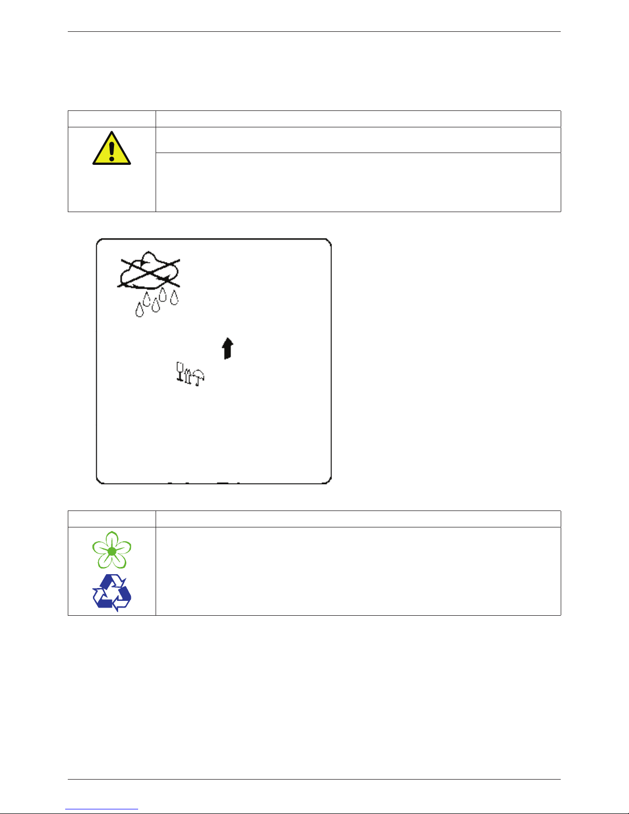
CAUTION Damage caused during transport or storage
Incorrect transport or storage, or the use of unsuitable lifting equipment might cause damage to the
device.
• The device must only be transported and stored by authorised and suitably trained technical
personnel.
• If you detect any damage, do not start the device.
• Adhere to the permissible storage and transport temperatures (see technical data).
• Protect the device against direct sunlight and heat radiation.
The device must be stored in the original
packaging. Seal the packaging and store it in a
dry and frost-free room. Ensure that the storage
temperature does not exceed the limits specied
on the type plate.
Even when packaged, take suitable measures to
protect the device against the elements.
While in storage, secure the device so that it
cannot topple over or fall, and protect it against
vibration.
NOTICE Recycling of packaging material
• The packaging material is recyclable. Dispose of the packaging material according to the applicable
statutory regulations.

EN Installation and operating manual
7 METPOINT® SF53
1.5. Intended use
The METPOINT® FLM is a thermal ow meter for the measurement of volume ow, consumption and ow velocity. By default, the
device is congured for the measurement of volume ow in m³/h, consumption in m³ and velocity in m/s.
• The METPOINT® FLM is primarily used in compressed air systems. On request, the sensor can be programmed by BEKO
TECHNOLOGIES GmbH for the measurement of other gases: nitrogen, argon, helium, carbon dioxide
• The device is not suitable for operation in potentially explosive or aggressive atmospheres.
• Protect the device against direct sunlight and heat radiation.
Operate the METPOINT® FLM only for the intended purpose and within the limit range specied in the technical data. Do not
operate the device with any media (uids, gas/vapour mixtures) other than those listed above. Any other use of the device is
deemed improper and poses a risk to persons, property and the environment.
1.6. Warranty and liability
All warranty shall be voided, if the METPOINT® FLM is used improperly, for a purpose other than the intended or is operated
outside the limits specified in the technical data. In such cases, the manufacturer shall also reject any liability for damages.
Improper operation includes:
• Incorrect installation, commissioning or operation; insucient maintenance
• Operation with defective components
• Non-compliance with the instructions in this document, in particular the safety instructions
• Modication of the device
• Non-compliance with the prescribed maintenance intervals
• Use of third-party spare parts that have not been approved by the manufacturer
Installation and operating manual EN
8 METPOINT® SF53
2. Product information
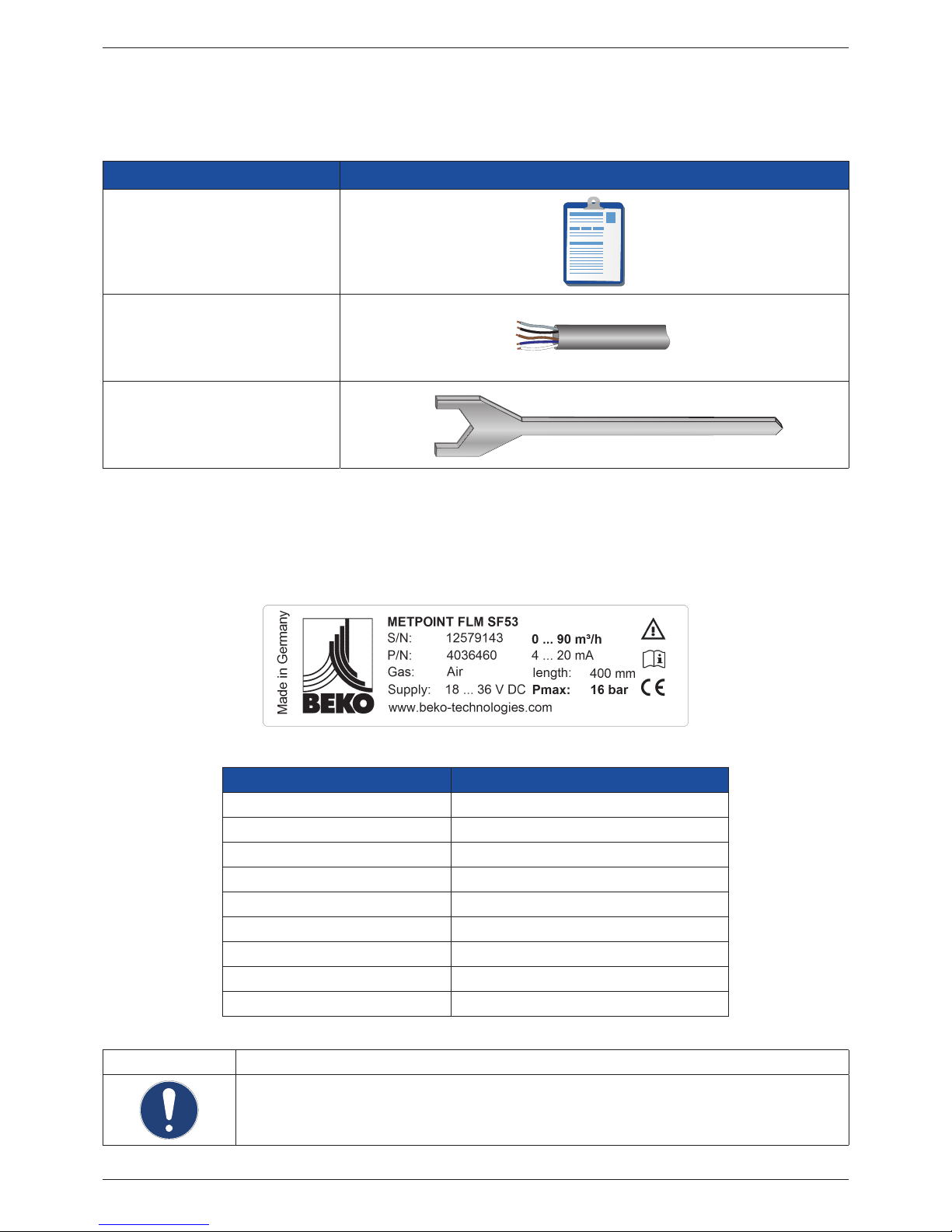
2.1. Scope of delivery
The table below shows the scope of delivery of the METPOINT® FLM.
Designation Picture
Calibration certicate
Connecting cable (5-wire)
Aligning aid
2.2. Type plate
The type plate is attached to the device housing. It contains all relevant technical data of the METPOINT® FLM. Please have these
details to hand when contacting the manufacturer or supplier:
Designation Description
METPOINT® FLM SF53 Type designation
S/N: 12579143 Serial number
P/N: 4036460 Product number
Gas: air Medium
Supply: 18 ... 36 V DC Power supply rating
0 ... 90 m³/h Min./max. measuring range
4 ... 20 mA Min./max. analog output current
Length: 400 mm Length of sensor tube
Pmax: 16 bar Max. permissible operating pressure
NOTICE Handling of type plate
Do not remove or cover the type plate, and protect it against damage.
For more information regarding the symbols printed on the type plate, see „Pictograms and symbols“
auf Seite 4.
EN Installation and operating manual
9 METPOINT® SF53
2.3. Product overview and description
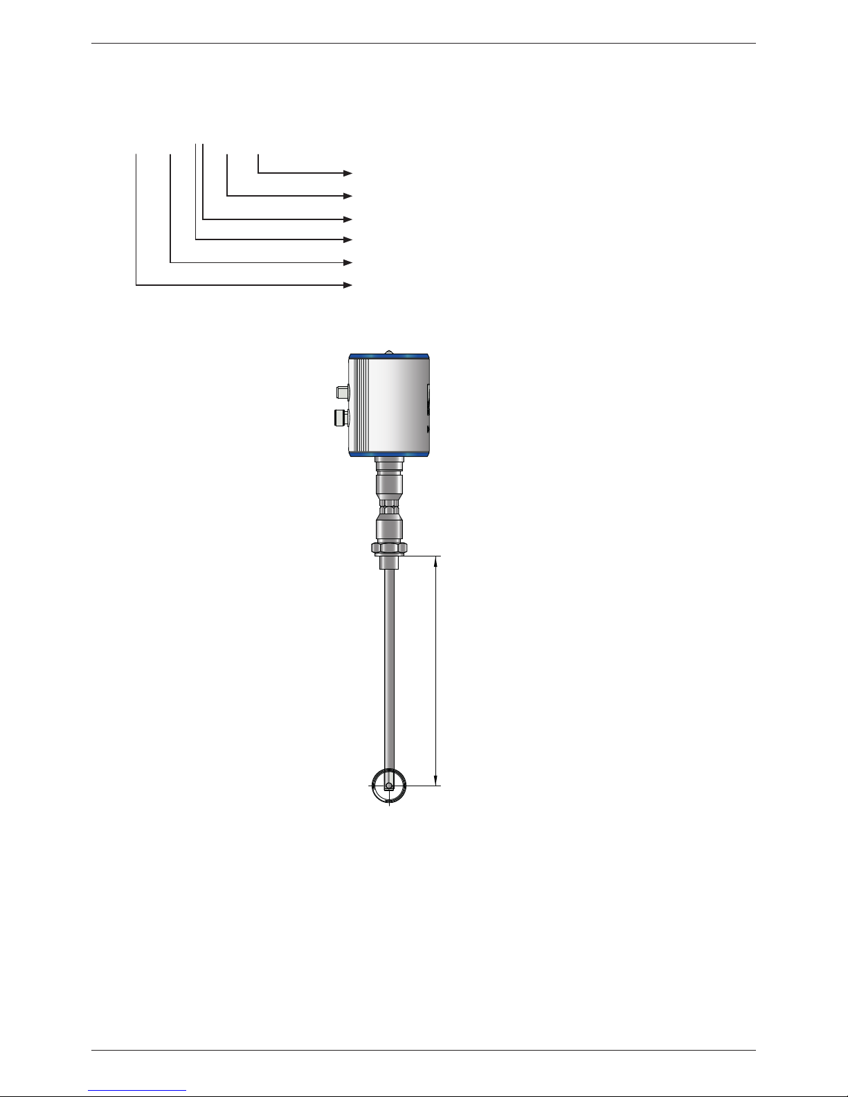
2.3.1. Identication based on product code
FLM
Sensor length (L)
Version with display
Interface: RS485
Operating pressure: 50 bar
SensorFlow (model designation)
FlowMeasurement (product designation)
SF 53
D
L220
L
Installation and operating manual EN
10 METPOINT® SF53
2.3.2. Product description
The METPOINT® FLM thermal ow meter measures the volume ow, which forms the basis for intelligent energy management.
It can be used to identify potential savings, overloads and weak points in a system to improve its eciency. By measuring the
actual ow to the various production units, operators are in a position to make decisions based on facts. The METPOINT® FLM
also indicates whether there are any leaks in their system. The METPOINT® FLM thus provides all the information operators need
to correctly dimension and congure their system and system components for improved eciency. The device is equipped with a
Modbus RTU(RS485) interface, a 4 ... 20 mA current output, a galvanically isolated pulse output and an optional MBus interface.
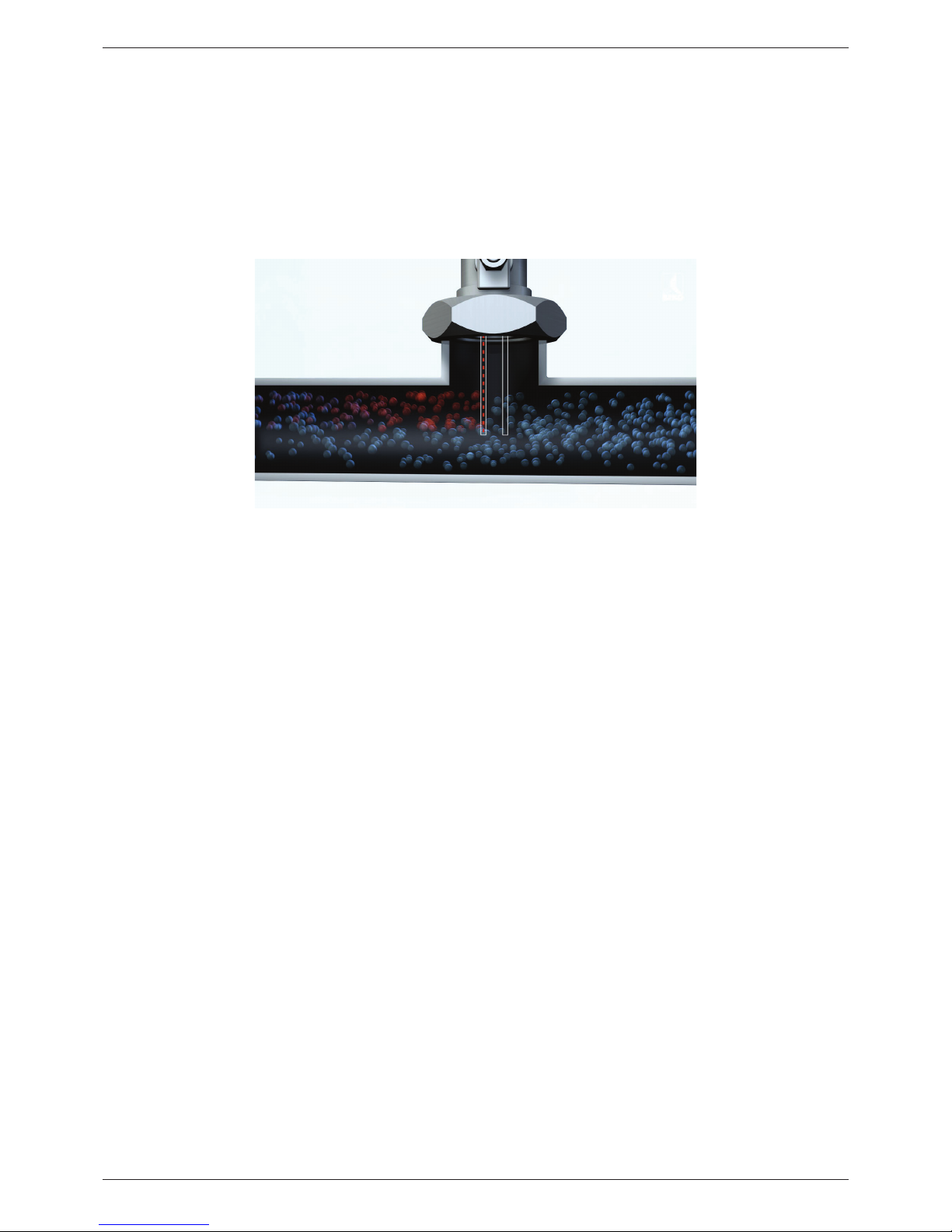
2.3.3. Operating principle
Two temperature sensors are installed in series in the direction of ow. The rst temperature sensor measures the current process
temperature, while the second sensor is electrically heated to a temperature that is exactly 40 K above the temperature measured
by the rst sensor. As the volume ow increases, the sensors would normally cool, but the electric heater of the second sensor
prevents such a temperature drop.
The electric energy required to maintain the temperature dierence is directly proportional to the volume ow. This energy
consumption of the heater is converted into the relevant ow measurements. Taking into account the inside diameter of the pipe,
the METPOINT® FLM determines the exact mass ow.
EN Installation and operating manual
11 METPOINT® SF53
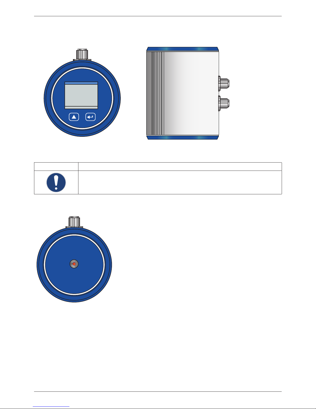
2.4. Control and display elements
2.4.1. Version with display
NOTICE Additional information
For more information regarding the operation of the device, see „Conguration and operation“ auf Seite
27.
2.4.2. Version with LED
The METPOINT® FLM features a LED calibration indicator mounted at the top of the housing. After 15 months, the LED begins to
ash, indicating that the device needs to be calibrated. The ashing LED does not have any eect on the measuring process, and
the device continues to provide accurate measuring signals.
On request, the calibration interval can be adjusted at the factory.
ME TPOINT® F LM
FLOW MEASURING
HW:1.00 SW:1.00
AIR
395,38
160515
m3/h
m
3
Plug-type connector A
Plug-type connector B
METPOINT® FLM
C
A
L
I
B
R
A
T
I
O
N
Installation and operating manual EN
12 METPOINT® SF53
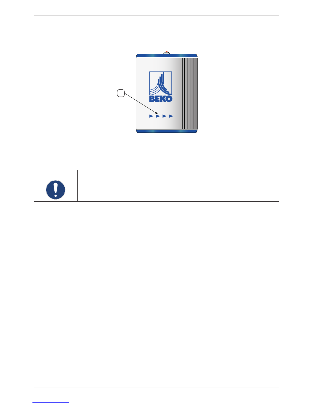
2.4.3. Direction of ow
The direction of ow is indicated by the arrows (1) on the housing of the METPOINT® FLM and on the sensor tube.
1
NOTICE Additional information
If necessary, turn the housing (e.g. to change the direction of ow through the device). For more
information, see „Turning housing“ auf Seite 18.
EN Installation and operating manual
13 METPOINT® SF53
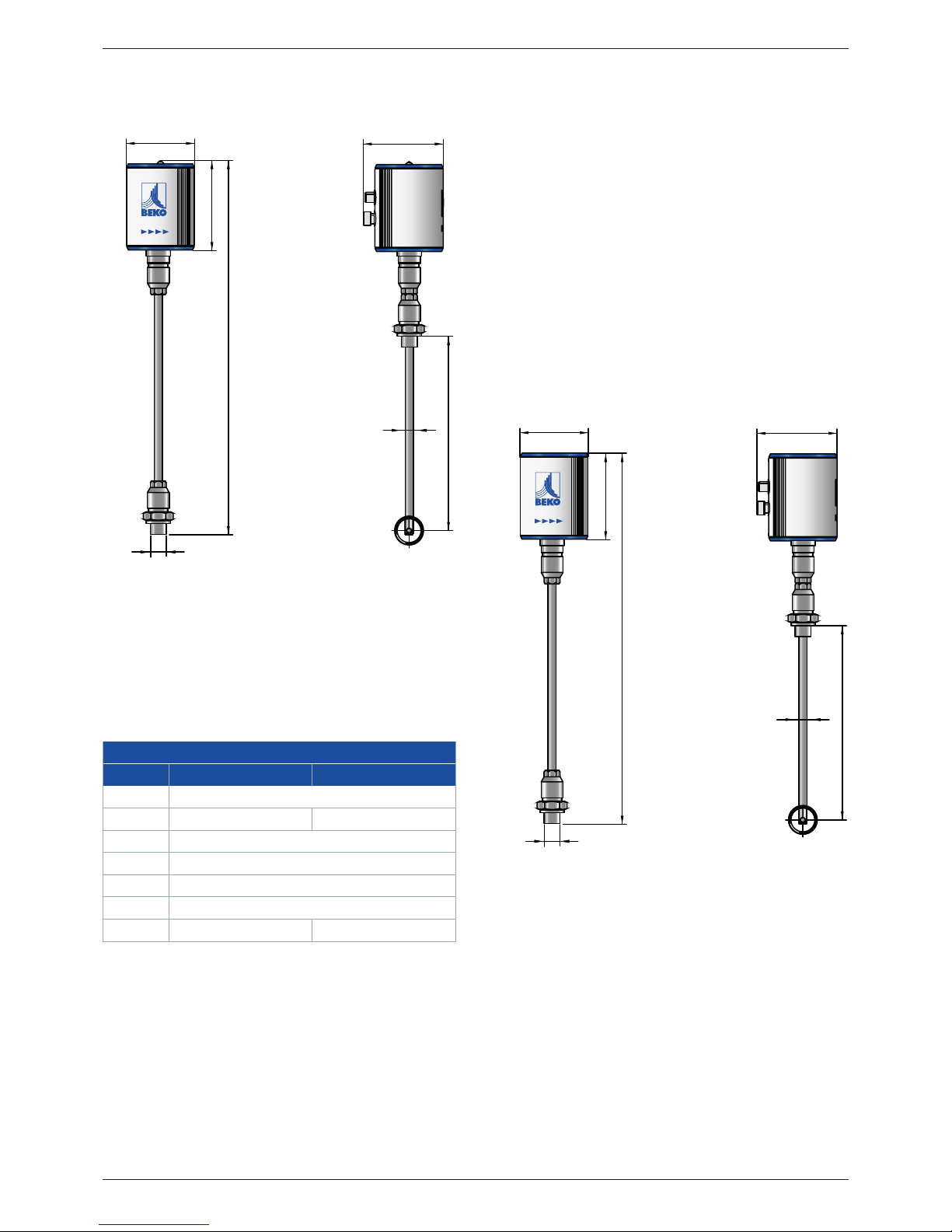
2.5. Dimensions
Dimensions
Version with display Version with LED
A G ½" (ISO 228/1)
B (mm) 415 (Standard) 418.5 (Standard)
C (mm) 80
D (mm) Ø 11.7
E (mm) 220 (standard), optional: 400
F (mm) 94
G (mm) 102 105.5
F
E
D
C
A
B
G
F
F
E
D
E
D
C
A
B
G
A
B
G
C

Installation and operating manual EN
14 METPOINT® SF53
2.6. Technical data
Technical data
SF53
Max. operating pressure 16 bar, optional 50 bar
Measuring technique Calorimetric
Operating temperature Sensor tube and ttings: -30 ... +140 °C
Housing: -30 ... +80 °C
Measured parameters m³/h (factory settings)
On the display version, the following units can be chosen:
m³/min, l/min, l/s, ft/min, cfm, m/s, kg/min, kg/s
Sensor Pt45, Pt1000
Media nitrogen, argon, helium, carbon dioxide
Humidity of medium max. 90 % rH (no droplets)
Power supply 18 ... 36 VAC
Power consumption max. 5 W
Digital output RS485 (Modbus RTU)
Analog output 4 ... 20 mA (max. load < 500 Ω)
Pulse output Floating switch contact
Passive: max. 48 VDC 150 mA
1 pulse per m³ or per litre
Unit adjustable at display
Accuracy ± 1.5 % of measured value
± 0.3 % of nal value
Display/indicator Display: TFT 1.8" (resolution: 220 x 167) or service LED
Screw tting G½ (ISO 228/1)
Material Sensor tube and ttings: 1.4301 stainless steel
Housing: Powder-coated aluminium
Flange: 1.4404 (DIN EN 1092-1)
 Loading...