

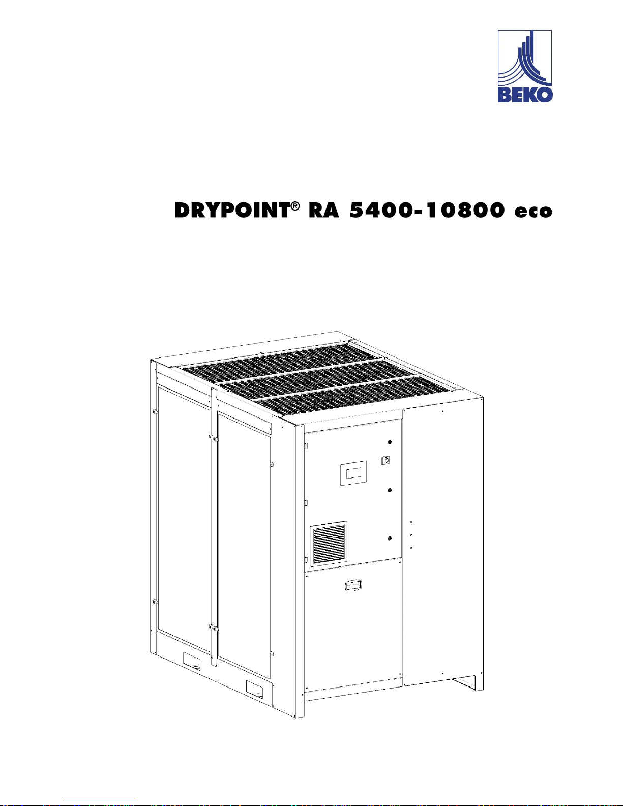
Beko DRYPOINT RA eco 6600-R, DRYPOINT RA eco 10800, DRYPOINT RA eco 5400-R, DRYPOINT RA eco 5400, DRYPOINT RA eco 7200-R Instructions For Installation And Operation Manual
...
EN - english
Instructions for installation and operation
Compressed air refrigeration dryer

2 DRYPOINT® RA 5400-10800 eco
Dear customer,
Thank you for deciding in favour of the DRYPOINT® RA 5400-10800 eco compressed-air refrigeration dryer. Please read
these installation and operating instructions carefully before mounting and starting up the DRYPOINT® RA 5400-10800
eco and follow our directions. Perfect functioning of the DRYPOINT® RA 5400-10800 eco and thus reliable compressedair drying can only be guaranteed when the provisions and notes stipulated here are strictly adhered to.

DRYPOINT® RA 5400-10800 eco 3
Contents
1 Name plate 5
2 Safety instructions 5
2.1 Safety pictograms in accordance with DIN 4844 6
2.2 Signal words in accordance with ANSI 7
2.3 Overview of the safety instructions 7
3 Proper use 10
4 Exclusion from a field of application 10
5 Instructions for the use of pressure equipment according to PED directive 2014/68/EU 10
6 Transport 11
7 Storage 11
8 Technical description 12
8.1 Control panel 12
8.2 Functional description 12
8.3 Flow diagram (Air-Cooled) 13
8.4 Flow diagram (Water-Cooled) 13
8.5 Refrigerating compressor 14
8.6 Condenser (air-cooled) 14
8.7 Condenser (water-cooled) 14
8.8 Cooling-water regulating valve 14
8.9 Filter dryer 14
8.10 Electronic Expansion Valve (EEV) 15
8.11 Alu-Dry module 15
8.12 Refrigerant pressure switches LPS - HPS 15
8.13 Compressor crankcase heater 15
8.14 Electrical panel fan 15
8.15 DMC50 electronic control unit 16
8.15.1 Starting the dryer (“ON” mode) 16
8.15.2 Stopping the dryer (“STANDBY” mode) 16
8.15.3 Performing the condensation drain test 16
8.15.4 Displaying process values T1, T2, T3, T4, HP, LP, % , % 17
8.15.5 How the DMC50 control unit displays and processes a service warning 18
8.15.6 How the DMC50 control unit displays and processes an alarm 19
8.15.7 Displaying the log file of stored alarms 21
8.15.8 Downloading the process values stored following an alarm 22
8.15.9 Displaying instantaneous process values for the compressor inverter 22
8.15.10 Displaying technical maintenance and energy savings data 23
8.15.11 Controlling the dryer from a remote workstation 24
8.15.12 How the alarm / service warning flagging contact operates 24
8.15.13 How the RS485 serial communication port operates 24
8.15.14 Displaying / changing process user parameters 25
8.15.15 Changing the system date / time 27
8.15.16 Changing the user interface language 27
8.16 Electronically level-controlled BEKOMAT condensate drain 28
9 Installation 29
9.1 Place of installation 29
9.2 Installation plan 30
9.3 Correction factors 31
9.4 Connection to the compressed-air system 32
9.5 Connection to the cooling-water network 33
9.6 Minimum cooling-water requirements: 33
9.7 Electrical connections 34
9.8 Condensate drain 35
10 Start-up 36
10.1 Preliminary stages 36
10.2 Initial start-up 37
10.3 Start-up and shut down 38
11 Technical data 39

4 DRYPOINT® RA 5400-10800 eco
11.1 Technical data DRYPOINT RA 5400-10800 eco 3/400/50 39
11.2 Technical data DRYPOINT RA 5400-10800 eco 3/460/60 40
12 Maintenance, troubleshooting, spare parts and dismantling 41
12.1 Checks and maintenance 41
12.2 Troubleshooting 42
12.3 Recommended spare parts 52
12.4 Maintenance works at the refrigeration cycle 53
12.5 Dismantling the dryer 53
13 Attachments 54
Exploded views – List of components 54
Electric diagrams – List of components 54
13.1 Dryers dimensions 55
13.1.1 DRYPOINT RA 5400-6600 eco 55
13.1.2 DRYPOINT RA 7200-8800 eco 55
13.1.3 DRYPOINT RA 10800 eco Air-Cooled 55
13.1.4 DRYPOINT RA 10800 eco Water-Cooled 55
13.2 Exploded views 55
13.2.1 DRYPOINT RA 5400-6600 eco Air-Cooled 55
13.2.2 DRYPOINT RA 5400-6600 eco Water-Cooled 55
13.2.3 DRYPOINT RA 7200-8800 eco Air-Cooled 55
13.2.4 DRYPOINT RA 7200-8800 eco Water-Cooled 55
13.2.5 DRYPOINT RA 10800 eco Air-Cooled 55
13.2.6 DRYPOINT RA 10800 eco Water-Cooled 55
13.3 Electric diagrams 55
13.3.1 DRYPOINT RA 5400-6600 eco 55
13.3.2 DRYPOINT RA 7200 eco 55
13.3.3 DRYPOINT RA 8800 eco 55
13.3.4 DRYPOINT RA 10800 eco 55
Name plate
DRYPOINT® RA 5400-10800 eco 5
Pos: 1 /Beko Technische Dokumentation/Ü berschriften/1/Sicherheitshinweise @ 0\mod_1 183637609261_6.doc @ 5365
1 Name plate
The name plate is on the back of the dryer and comprises all primary data of the device. Always refer to these data when
contacting the manufacturer or the sales department.
All guarantee claims will expire in the event that the name plate is modified or removed.
The dryer model printed on the nameplate includes one or more suffixes that specify one or more features of dryer.
Explanation of 1st suffix for power supply requirements :
1st SUFFIX
DESCRIPTION OF FEATURE
none
3/400/50
-R
3/460/60
-S
3/230/60 (with internal autotransformer)
-F
3/380/60 (with internal autotransformer)
-T
3/690/60 (with internal autotransformer)
Explanation of 2nd suffix for cooling requirements :
2nd SUFFIX
DESCRIPTION OF FEATURE
/ AC
Air cooled
/ WC
Fresh water cooled
/ SWC
Sea water cooled, tube bundle condenser
/ TBH
Fresh water cooled, tube bundle condenser
Explanation of (eventual) 3rd suffix for special feature :
3rd SUFFIX
DESCRIPTION OF FEATURE
-TAC
Anti corrosion treatment
-SP
Special feature
-OF
Dryer oil free
Examples : DP RA2200-R /AC eco → DRYPOINT RA2200 eco, 3/460/60, Air cooled
DP RA1800 /SWC eco → DRYPOINT RA1800 eco, 3/400/50, Sea water cooled, tube bundle cond.
DP RA2200-T /WC eco → DRYPOINT RA2200 eco, 3/690/60, Water cooled
2 Safety instructions
Pos: 2 /Beko Technische Dokumentation/Gl obale Texte/Allgemeiner Hinweis BM @ 0\mo d_1183615737313_6.doc @ 4004
Pos: 3 /Beko Technische Dokumentation/Sic herheit/Hinweis Anleitung BEKO @ 0\mod_11 84147787557_6.doc @ 5758
Please check whether or not these instructions correspond to the device type.
Please adhere to all advice given in these operating instructions. They include essential information which
must be observed during installation, operation and maintenance. Therefore, it must be ensured that these
operating instructions are read by the fitter and the responsible operator / certified skilled personnel prior
to installation, start-up and maintenance.
The operating instructions must be accessible at all times at the place of application of the DRYPOINT®
RA 5400-10800 eco compressed-air refrigeration dryer.
In addition to these operating instructions, local and national regulations need to be observed, where
required.
Ensure that operation of the DRYPOINT® RA 5400-10800 eco compressed-air refrigeration dryer only
takes place within the permissible limit values indicated on the name plate. Any deviation from these limit
values involves a risk for persons and for the material, and may result in malfunction or a breakdown.
After installing the device correctly and in accordance with the instructions in this manual, the dryer is
ready to operate, further settings are not required. Operation is fully automatic and maintenance is limited
to several examinations and cleaning measures which are described in the following chapters.
This manual must be available at all times for future reference and is a constituent part of the dryer.
If you have any queries regarding these installation and operating instructions, please contact BEKO
TECHNOLOGIES GMBH.
Safety instructions
6 DRYPOINT® RA 5400-10800 eco
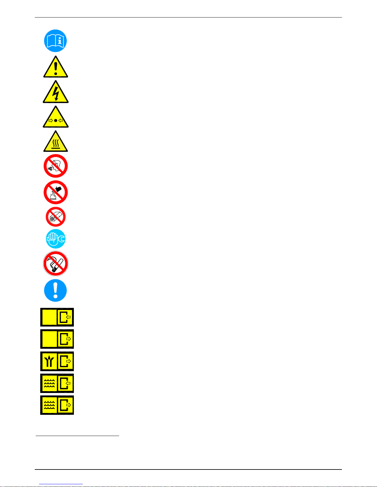
2.1 Safety pictograms in accordance with DIN 4844
Observe operating instructions
General danger symbol
Supply voltage
Danger: component or system under pressure
Hot surfaces
Non-breathable air
Do not use water to extinguish the fire
Do not operate with open cover (housing)
Maintenance works or controlling measures must only be carried out by qualified personnel 1
Do not smoke
Note
Pos: 4 /Beko Technische Dokumentation/Sic herheit/Gefahr Druckluft @ 0\mod_11841481 43854_6.doc @ 577
6
Connection point compressed-air inlet
Connection point compressed-air outlet
Connection point condensate drain
Connection point cooling-water inlet (water-cooled)
Connection point cooling-water outlet (water-cooled)
1
Certified skilled personnel are persons who are authorised by the manufacturer, with experience and technical training, who are well-
grounded in the respective provisions and laws and capable of carrying out the required works and of identifying and avoiding any
risks during the machine transport, installation, operation and maintenance.
Qualified and authorised operators are persons who are instructed by the manufacturer regarding the handling of the refrigeration
system, with experience and technical training, and who are well-grounded in the respective provisions and laws.
ARIA
AIR
LUFT
AIR
ARIA
AIR
LUFT
AIR
Safety instructions
DRYPOINT® RA 5400-10800 eco 7
Works can be carried out by the operator of the plant, provided that they are skilled accordingly 2.
NOTE: Text that contains important specifications to be considered – does not refer to safety precautions.
The device was carefully designed with particular attention paid to environmental protection:
• CFC-free refrigerants
• CFC-free insulation material
• Energy-saving design
• Limited acoustic emissions
• Dryer and packaging comprise reusable materials
This symbol advises the user to observe the environmental aspects and comply with the recommendations connected
with this symbol.
2.2 Signal words in accordance with ANSI
Danger!
Imminent hazard
Consequences of non-observance: serious injury or death
Warning!
Potential hazard
Consequences of non-observance: possible serious injury or death
Caution!
Imminent hazard
Consequences of non-observance: possible injury or property damage
Notice!
Potential hazard
Consequences of non-observance: possible injury or property damage
Important!
Additional advice, info, hints
Consequences of non-observance: disadvantages during operation and maintenance, no danger
2.3 Overview of the safety instructions
Certified skilled personnel
Installation works must exclusively be carried out by authorised and qualified skilled personnel. Prior to
undertaking any measures on the DRYPOINT® RA 5400-10800 eco compressed-air refrigeration dryer,
the certified skilled personnel shall read up on the device by carefully studying the operating instructions.
The operator is responsible for the adherence to these provisions. The respective directives in force apply
to the qualification and expertise of the certified skilled personnel.
For safe operation, the device must only be installed and operated in accordance with the indications in
the operating instructions. In addition, the national and operational statutory provisions and safety
regulations, as well as the accident prevention regulations required for the respective case of application,
need to be observed during employment. This applies accordingly when accessories are used.
Danger!
Compressed air!
Risk of serious injury or death through contact with quickly or suddenly escaping compressed air
or through bursting and/or unsecured plant components.
Compressed air is a highly dangerous energy source.
Never work on the dryer when the system is under pressure.
Never direct the compressed-air outlet or condensate drain hoses at persons.
The user is responsible for the proper installation of the dryer. Non-observance of the instructions in the
"Installation" chapter leads to the expiration of the guarantee. Improper installation may result in
dangerous situations for the personnel and/or the device.
Pos: 5 /Beko Technische Dokumentation/Sic herheit/Maßnahmen Druckluft BM @ 0\mod_ 1184148284291_6.doc @ 5812
Pos: 6 /Beko Technische Dokumentation/Sic herheit/Gefahr Netzspannung @ 0\mod_1184 148186948_6.doc @ 5794
Danger!
Supply voltage!
Contact with non-insulated parts carrying supply voltage involves the risk of an electric shock
resulting in injuries and death.
2
Certified skilled personnel are persons who are authorised by the manufacturer, with experience and technical training, who are wellgrounded in the respective provisions and laws and capable of carrying out the required works and of identifying and avoiding any
risks during the machine transport, installation, operation and maintenance.
Qualified and authorised operators are persons who are instructed by the manufacturer regarding the handling of the refrigeration
system, with experience and technical training, and who are well-grounded in the respective provisions and laws.
Safety instructions
8 DRYPOINT® RA 5400-10800 eco
Only qualified and skilled personnel are authorised to run electrically-operated devices. Prior to
undertaking maintenance measures at the device, the following requirements must be met:
Make sure that the power supply is switched off and that the device is off and marked for maintenance
measures. Please also ensure that the power supply cannot be re-established during the works.
Prior to carrying out maintenance works at the dryer, switch it off main switch (control panel pos.1) and
wait for at least 30 minutes.
Pos: 7 /Beko Technische Dokumentation/Sic herheit/Maßnahmen Netzspannung BM 31/32/33 @ 0\mod_1216898430699_6.doc @ 11319
Caution!
Refrigerant!
The compressed-air refrigeration dryer uses HFC-containing refrigerants as a coolant.
Please observe the corresponding paragraph entitled "Maintenance works at the refrigeration cycle".
Warning!
Refrigerant leak!
A refrigerant leak involves the danger of serious injury and damage to the environment.
The DRYPOINT® RA 5400-10800 eco compressed-air refrigeration dryer contains fluorinated greenhouse
gas/refrigerant.
Installation, repair and maintenance works at the refrigeration system must only be carried out by certified
skilled personnel (specialists). A certification in accordance with EC regulation 303/2008 must be
available.
The requirements of the EC 842/2006 directive must be met under all circumstances.
Please refer to the indications on the name plate as regards the type and amount of refrigerant.
Comply with the following protective measures and rules of conduct:
• Storage: Keep the container tightly closed. Keep it in a cool and dry place. Protect it against heat and
direct sunlight. Keep it away from ignition sources.
• Handling: Take measures against electrostatic charging. Ensure good ventilation/suction at the
workplace. Check fittings, connections and ducts for tightness. Do not inhale the gas. Avoid contact
with the eyes or the skin.
• Prior to carrying out works on refrigerant-carrying parts, remove the refrigerant to such an extent that
safe working is possible.
• Do not eat, drink or smoke during work. Keep out of the reach of children.
• Breathing protection: ambient-air-independent respirator (at high concentrations).
• Eye protection: sealing goggles.
• Hand protection: protective gloves (e.g. made of leather).
• Personal protection: protective clothing.
• Skin protection: use protective cream.
In addition, the safety data sheet for the refrigerant needs to be observed!
Caution!
Hot surfaces!
During operation, several components can reach surface temperatures of more than +60°C. There
is the risk of burns.
All components concerned are installed inside of the closed housing. The housing must only be opened
by certified skilled personnel 3.
Caution!
Improper use!
The device is intended for the separation of water in compressed air. The dried compressed air cannot be
used for breathing-air purposes and is not suitable for the direct contact with food.
This dryer is not suitable for the treatment of contaminated air or of air containing solids.
3
Certified skilled personnel are persons who are authorised by the manufacturer, with experience and technical training, who are wellgrounded in the respective provisions and laws and capable of carrying out the required works and of identifying and avoiding any
risks during the machine transport, installation, operation and maintenance.
Qualified and authorised operators are persons who are instructed by the manufacturer regarding the handling of the refrigeration
system, with experience and technical training, and who are well-grounded in the respective provisions and laws.
Safety instructions
DRYPOINT® RA 5400-10800 eco 9
Note!
Contaminated intake air!
In the event that the intake air is strongly contaminated (ISO 8573.1 class 3.-3 or poorer quality), we
recommend the additional installation of a prefilter (e.g. CLEARPOINT F040), to avoid clogging of the heat
exchanger.
Caution!
Heating-up through fire!
In the event of a heating-up through fire, the containers and pipes of the refrigerant system can
burst.
In this case, please proceed as follows:
Switch off the refrigeration plant.
Switch off the mechanical ventilation of the machinery compartment.
Use ambient-air-independent respirators.
Containers and plants which are filled with refrigerant can burst violently in the event of fire.
The refrigerants themselves are incombustible, but they are degraded to very toxic products at high
temperatures.
Remove the container/plant from the fire zone, as there is the risk of bursting!
Cool down containers and bottles via a directed water jet from a safe position.
In the event of fire, please use an approved fire extinguisher. Water is not a suitable agent to extinguish
an electrical fire.
This must only be carried out by persons who are trained and informed about the hazards emanating
from the product.
Caution!
Unauthorised intervention!
Unauthorised interventions may endanger persons and plants and lead to malfunction.
Unauthorised interventions, modification and abuse of the pressure devices are prohibited.
The removal of sealings and leadings at safety devices is prohibited.
Operators of the devices must observe the local and national pressure equipment regulations in the
country of installation.
Pos: 8 /Beko Technische Dokumentation/Sic herheit/Sicherheitshinweise, weitere BM (nicht E x) @ 0\mod_1183616103770_6.doc @ 4009os: 9 /Beko Technische Dokumentation/Sicherheit/Zus atz Sicherheitshinweise BM33 @ 0\mod_123192 6887620_6.doc @ 12829s: 10 /Beko Technische Do kumentation/Sicherheit/Vorsicht Fehlfunktion @ 0\mod_1214378096290_6.doc @ 9359
Note!
Ambient conditions!
In the event that the dryer is not installed under suitable ambient conditions, the ability of the device to
condense refrigerant gas is impaired. This can result in a higher load of the refrigerating compressor, and
in a loss of efficiency and performance of the dryer.
This in turn leads to overheated condenser fan motors, to malfunction of electric components and to a
breakdown of the dryer. Failures of this type will affect warranty considerations.
Do not install the dryer in an environment in which chemicals with a corrosive effect, explosive gases, toxic
gases, evaporation heat, high ambient temperatures or extreme dust and dirt can be found.

Proper use
10 DRYPOINT® RA 5400-10800 eco
Pos: 12 /Beko Technische Dokumentation/Üb erschriften/1/Bestimmungsgemäße Verwendung @ 0\mod_1183637706293_6.doc @ 5383
3 Proper use
This dryer was designed, manufactured and tested to separate the moisture which normally exists in compressed air.
Any other use is considered improper.
The manufacturer shall not be liable for problems occurring as a consequence of improper use. The user alone is
responsible for any damage resulting from that.
Furthermore, the correct use includes the compliance with the installation instructions, in particular in respect of:
• The voltage and frequency of the main voltage supply.
• The pressure, temperature and flow rate of the inlet air.
• The pressure, temperature and cooling-water throughput (water-cooled).
• The ambient temperature.
When delivered, the dryer is tested and fully assembled. The customer only needs to connect the device to the system
in accordance with the instructions in the following chapters.
Pos: 15 /Beko Technische Dokumentation/Üb erschriften/1/Ausschluss vom Anwendungsbereich @ 0\mod_1236003439359_6.doc @ 13709
4 Exclusion from a field of application
Pos: 16 /Beko Technische Dokumentation/B estimmungsgemäße Verwendung/BEKOMAT/Ausschl uß Anwendung BM 31/32/33 @ 0\mod_12 36003837511_6.doc @ 13736
Note!
Improper use!
The device is intended for the separation of water in compressed air. The dried compressed air cannot
be used for breathing-air purposes and is not suitable for the direct contact with food.
This dryer is not suitable for the treatment of contaminated air or of air containing solids.
5 Instructions for the use of pressure equipment according to PED directive 2014/68/EU
The DRYPOINT® RA 5400-10800 eco compressed-air refrigeration dryer contains pressure equipment in the sense of
the 2014/68/EU Pressure Equipment Directive. Therefore, the entire plant needs to be registered with the supervisory
authority if required in accordance with the local regulations.
For the examination prior to the start-up and for periodic inspections, the national regulations need to be observed, such
as the industrial safety regulation in the Federal Republic of Germany. In countries outside the EU, the respective
regulations in force there need to be adhered to.
The proper use of pressure devices is the basic requirement for safe operation. As regards pressure devices, the
following points need to be observed:
• The DRYPOINT® RA 5400-10800 eco compressed-air refrigeration dryer must only be employed within the pressure
and temperature range limits indicated by the manufacturer on the name plate.
• No welding must be carried out on the pressure parts.
• The DRYPOINT® RA 5400-10800 eco compressed-air refrigeration dryer must neither be installed in insufficiently
ventilated rooms nor near heat sources or inflammable substances.
• To avoid fractures resulting from material fatigue, the refrigeration dryer should not be exposed to vibrations during
operation.
• The maximum operating pressure indicated by the manufacturer on the name plate must not be exceeded. It is the
installer's responsibility to install the appropriate safety and control devices. Prior to the start-up of the DRYPOINT®
RA 5400-10800 eco compressed-air refrigeration dryer, the connected pressure generator (compressor etc.) must
be set to the max. permissible operating pressure. The integrated safeguard needs to be checked by an approved
inspection agency.
• The documents related to the DRYPOINT® RA 5400-10800 eco compressed-air refrigeration dryer (manual,
operating instructions, manufacturer's declaration etc.) must be kept safe for future reference.
• No objects whatsoever must be installed at or placed on the DRYPOINT® RA 5400-10800 eco compressed-air
refrigeration dryer and the connecting lines.
• Installation of the plant in frost-free places only.
• Operation of the plant is only permissible with fully closed and intact housing and cover panels. Operation of the
plant with damaged housing/cover panels is prohibited.
Transport
DRYPOINT® RA 5400-10800 eco 11
6 Transport
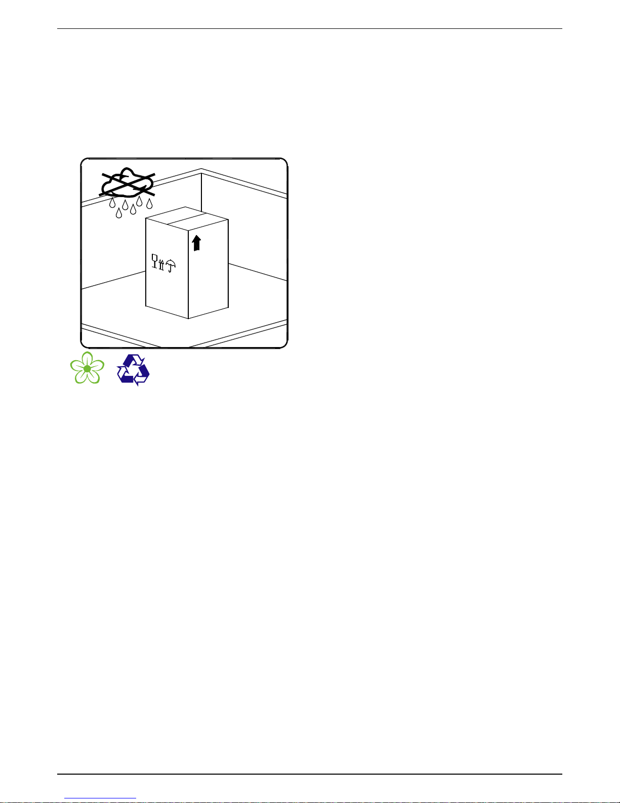
Check the packaging for visible loss or damage. If no visible damage can be ascertained, place the unit in close proximity
to the place of installation and unpack the device.
During this procedure, the dryer must always remain in an upright position. The components may be damaged when the
unit is tilted or turned upside down.
Store the device in a dry environment and do not expose it to extreme weather conditions.
Handle with care. Strong shocks can cause irreparable damage.
7 Storage
Keep the device away from extreme weather conditions
even when packaged.
Keep the dryer in an upright position, also while it is stored.
Tilting the device or turning it upside down can cause
irreparable damage to some components.
When the dryer is not in use, it can be stored in its
packaging in a dust-free and protected place at a
temperature min.+1° … max.+50°C and at a specific
humidity of max. 90%. If the storage period exceeds 12
months, you should contact the manufacturer.
The packaging material is recyclable. Dispose of the material in accordance with the
directives and provisions in force in the country of destination
SCC0001
Technical description
12 DRYPOINT® RA 5400-10800 eco
8 Technical description
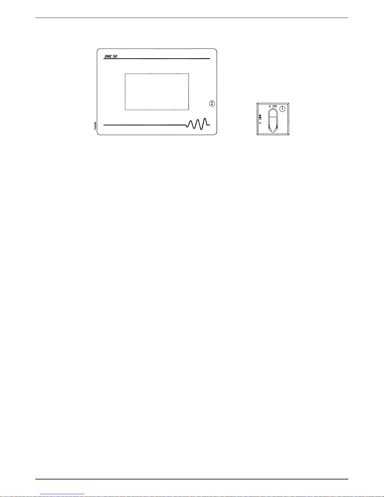
8.1 Control panel
The control panel explained below is the only dryer user interface.
1
Main switch
2 Electronic controller DMC50
8.2 Functional description
Operating principle – The dryer models described in this manual operate all on the same principle. The hot moisture
laden air enters an air to air heat exchanger. The air then goes through the evaporator, also known as the air to refrigerant
heat exchanger. The temperature of the air is reduced to approximately 2°C, causing water vapor to condense to liquid.
The liquid is continuously coalesced and collected in the separator for removal by the condensate drain. The cool
moisture free air then passes back through the air to air heat exchanger to be reheated to within 8 degrees lower than
the incoming air to the dryer.
Refrigeration circuit – Refrigerant gas is exhausted by the compressor and exits at high pressure towards a condenser
where heat is removed causing the refrigerant to condense to a high-pressure liquid state. The liquid is forced through an
electronic expansion valve (EEV) where the resulting pressure drop allows the refrigerant to boil off at a predetermined
temperature. Low-pressure liquid refrigerant enters the heat exchanger where heat from the incoming air is transferred
causing the refrigerant to boil; the resulting phase change produces a low pressure and low temperature gas. Then the
low-pressure gas goes back to the compressor, where it is re-compressed and begins the cycle again.
Operation in eco mode (Variable Speed) – The DMC50 electronic controller constantly monitors the evaporating
pressure (BLP), the condensing pressure (BHP) and the temperature of the DewPoint (BT1).
At each compressor start-up VS (Variable Speed) compressor’s speed is forced to a fixed speed (approx. 40-50% of its
maximum speed) for approx. 3 minutes to allow a proper oil circulation in the refrigerant circuit. During this period, if the
evaporating pressure (BLP) falls too low, DMC50 will activate a solenoid valve EVB that will increase the evaporating
pressure above the freezing point.
Expired the first 3 minutes, DMC50 will adjust VS compressor’s speed in order to keep the evaporating pressure almost
constant, allowing a constant dewpoint even with dryer thermal load variation.
Having an higher load to the dryer, the capacity of the VS compressor to its maximum speed is insufficient, the evaporation
pressure tends to increase beyond the set-point, so the FIX speed (on-off) compressor is activated increasing the system
cooling capacity. At this point VS compressor speed is automatically adjusted to maintain the evaporation pressure to
the set-point. In DP RA8800-10800 eco an additional FIX speed (on-off) compressor is installed to increase the system
cooling capacity.
When the load to the dryer decreases, with VS and FIX compressors turned on, the speed of the VS compressor is
decreased up to its minimum value; if the cooling capacity is still too high, the FIX compressor is switched off and VS
compressor speed is automatically adjusted to maintain the evaporation pressure to the set-point.
In very low load conditions (or no load), VS compressor will run at its lowest allowable speed. If that speed is larger than
load demand, the evaporating pressure will decrease from its setting point and when the temperature of the DewPoint
tends to fall close to the freezing point, the DMC50 controls the switching off of the VS compressor.
The VS compressor will be started again when the DewPoint temperature and evaporating pressure rises above a target
value.
The VS compressor is always the first to start and is always the last to stop.
The check valve CHV in combination with the Electronic Expansion Valve (EEV) help to extend the off time of the
compressor and avoid the immediate balancing of high and low pressures of the refrigerant circuit. The solenoid valve
EVB is activated before the compressor start as long as refrigerant pressures (low and high) get balanced.
Fan(s) speed will be controlled by the DMC50 in order to keep the condensing pressure measured by BHP almost constant
(air cooled).
With these dryers, the energy consumption will be adjusted closely proportional to the thermal load applied to the dryer
itself, allowing considerable energy savings in the majority of applications
Technical description
DRYPOINT® RA 5400-10800 eco 13
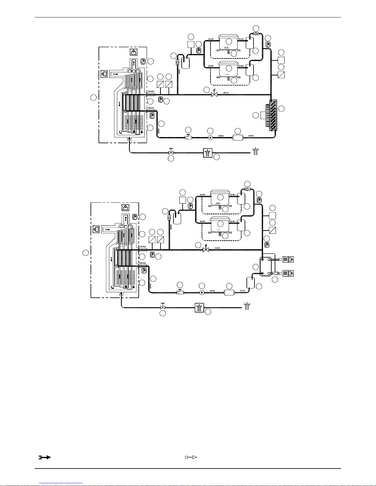
8.3 Flow diagram (Air-Cooled)
8.4 Flow diagram (Water-Cooled)
1
Alu-Dry module
18
Condenser (Water-Cooled)
1a
Air-to-air heat exchanger
19
Condenser water regulating valve (Water-Cooled)
1b
Air-to-refrigerant heat exchanger
20
Refrigerant accumulator
1c
Condensate separator
21
Electronic drainer
2
Refrigerant pressure switch LPS
25
Compressor crankcase heater
4
Refrigerant pressure switch HPS
34
Liquid sight glass
6f
Compressor FIX
35
Electronic Expansion Valve EEV
6v
Compressor VS
36
Liquid separator
8
Condenser (Air-Cooled)
37
Refrigerant pressure transducer BHP
9
Condenser fan (Air-Cooled)
39
Refrigerant pressure transducer BLP
10
Filter dryer
43
Oil separator
12.1
T1 Temperature probe – DewPoint
82
Check valve CHV
12.2
T2 Temperature probe – Air IN
85
Pressure balancing solenoid valve EVB
12.3
T3 Temperature probe – Compressor suction
86
Electronic Expansion Valve temperature sensor BS
12.4
T4 Temperature probe – Compressor discharge
87
Electronic Expansion Valve pressure transducer
BP
13
Condensate drain service valve
Compressed air flow direction
Refrigerant gas flow direction
13
1
1c
T1
1b
1a
10
85
6v
9
M
8
T2
12.2
25
DGF0149
21
12.1
4
P>
mA
P
37
T4
12.4
34
35
6f
25
43
82d
VS
FIX
43
P<
2
12.3
39
mA
P
82
87
V
P
BS
86
13
1
1c
T1
1b
1a
10
85
6v
T2
12.2
25
DGF0150
21
12.1
4
P>
mA
P
37
T4
12.4
34
35
6f
25
43
82d
VS
FIX
43
P<
2
12.3
39
mA
P
82
87
V
P
BS
86
20
18
19
T4
12.4

Technical description
14 DRYPOINT® RA 5400-10800 eco
8.5 Refrigerating compressor
The refrigerating compressor is the pump of the system, gas coming from the evaporator (low pressure side) is
compressed up to the condensation pressure (high pressure side). Dryer is equipped with multiple compressors, of which
one in variable speed.
Variable speed compressor
It is used a scroll fully hermetic compressor encapsulated with a BLDC (Brush Less Direct Current) motor which is the
latest and most efficient technology available for this application. Compressor motor speed is completely handled by an
heavy duty inverter, with a customized software capable to ensure a very wide capacity regulation. Compressor motor
protection is completely managed by the inverter
FIX speed compressor
It is used a scroll fully hermetic compressor encapsulated with an AC motor. Compressor is activated ON/OFF according
to the thermal load. The integrated safeguard protects the compressor against overheating and excess current. The
protection is automatically reset as soon as the nominal conditions are reached again.
8.6 Condenser (air-cooled)
The condenser is the component in which the gas coming from the compressor is cooled down and condensed becoming
a liquid. Mechanically, a serpentine copper tubing circuit (with the gas flowing inside) is encapsulated in an aluminium
fin package.
RA 5400-8800: The cooling operation occurs via a high efficiency fan(s) AC motor, creating airflow within the dryer,
moving air through the fin package. The fan(s) motor speed is completely handled by an heavy duty inverter, with a
customized software capable to ensure a very wide capacity regulation.
RA 10800: The cooling operation occurs via a high efficiency fan(s) DC motor with integrated inverter, creating airflow
within the dryer, moving air through the fin package. The fan(s) motor speed is completely handled by the fan integrated
inverter capable to ensure a very wide capacity regulation.
It’s mandatory that the ambient air temperature does not exceed the nominal values. It is also important to keep the
condenser unit free from dust and other impurities.
8.7 Condenser (water-cooled)
The condenser is the component in which the gas coming from the compressor is cooled down and condensed becoming
a liquid. Basically it is a water/refrigerating gas exchanger where the cooling water lowers the temperature of the
refrigerating gas.
The temperature of the inlet water must not exceed the nominal values. It must also guarantee an adequate flow and
that the water entering the exchanger is free from dust and other impurities.
8.8 Cooling-water regulating valve
The condenser water regulating valve is used to keep the condensing pressure/temperature constant when the WaterCooled is being used. Thanks to the capillary tube, the valve detects the pressure in the condenser and consequently
adjusts the water flow. When the dryer stops the valve automatically closes the cooling water flow.
The condenser water regulating valve is an operating control device.
The closure of the water circuit from the pressure condenser water regulating valve cannot be used as a safety
closure during service operations on the system.
ADJUSTMENT
The condenser water regulating valve is adjusted during the testing phase to a pre-set value that covers 90%
of the applications. However, sometimes the extreme operating conditions of the dryer may require a more
accurate calibration.
During start-up, a qualified technician should check the condensing pressure/temperature and if necessary
adjust the valve by using the screws on the valve itself.
To increase the condensing temperature, turn the adjusting screws counter-clockwise; to lower it turn the
screws clock-wise.
Water valve setting : R134.a pressure 10 barg (± 0.5 bar)
R407C pressure 16 barg (± 0.5 bar)
8.9 Filter dryer
Traces of humidity and slag can accumulate inside the refrigerant circuit. Long periods of use can also produce sludge.
This can limit the lubrication efficiency of the compressor and clog the expansion valve. The function of the filter drier,
located before the expansion valve, is to eliminate any impurities from circulating through the system.

Technical description
DRYPOINT® RA 5400-10800 eco 15
8.10 Electronic Expansion Valve (EEV)
The electronic expansion valve (EEV) is an expansion device which is composed by a valve body operated from a
stepper motor. This component is managed from its driver according to heat exchanger superheating.
This parameter is calculated from the driver using a temperature sensor BS and a pressure sensor BP installed at
evaporator outlet refrigerant pipe. The driver operates the motor opening or closing the electronic expansion valve
(EEV) in order to keep constant at the setpoint the superheating.
On this dryer type, every Alu-Dry module has its electronic expansion valve EEV which control its superheating
independently.
In case of multiple Alu-Dry module (1…n), every group composed by electronic expansion valve EEV (1…n), every
temperature sensor BS (1…n), every pressure sensor BP (1…n) and every driver DRV (1…n) is marked with a sticker.
The number on the sticker (1…n) identify the valve group.
8.11 Alu-Dry module
The heat exchanger module houses the air-to-air, the air-to-refrigerant heat exchangers and the demister type
condensate separator. The counter flow of compressed air in the air-to-air heat exchanger ensures maximum heat
transfer. The generous cross section of flow channel within the heat exchanger module leads to low velocities and
reduced power requirements. The generous dimensions of the air-to-refrigerant heat exchanger plus the counter flow
gas flow allows full and complete evaporation of the refrigerant (preventing liquid flood back to the compressor). The high
efficiency condensate separator is located within the heat exchanger module. No maintenance is required and the
coalescing effect results in a high degree of moisture separation.
8.12 Refrigerant pressure switches LPS - HPS
To ensure the operational reliability and the protection of the dryer, a series of pressure switches are installed in the gas
cycle.
LPS :
Low-pressure guard on the suction side of the compressor, which is triggered when the pressure drops below
the predetermined value. The values are reset automatically as soon as the nominal conditions are reestablished.
Calibrated pressure :
R 134.a
Stop 0.7 barg - Restart 1.7 barg
R 407 C
Stop 1.7 barg - Restart 2.7 barg
HPS :
The high-pressure control unit on the discharge side of the compressor is activated when the pressure exceeds
the predetermined value. It features a manual-resetting button mounted on the protection device.
Calibrated pressure :
R 134.a
Stop 20 barg - Manual reset (P<14 bar)
R 407 C
Stop 30 barg - Manual reset (P<23 bar)
8.13 Compressor crankcase heater
At low temperatures oil can more easily be mixed with the refrigerant gas. So, when the compressor starts, oil can be
drawn into the refrigeration circuit and liquid flood back to the compressor could occur.
To prevent this, an electrical resistance heater is installed in the bottom part of the compressor. When the system is
powered and the compressor is not running, this heater keeps the oil at the correct temperature.
Note!
During short-term shut down (max. two to three days), it is advisable to leave the dryer and the control
panel connected to the supply current circuit. Otherwise, it would be necessary at a restart of the dryer to
wait two hours, until the oil in the compressor has reached the specified operating temperature.
8.14 Electrical panel fan
Drivers enclosed in the electrical panel dissipates a consistent amount of heat. If the electrical panel temperature rises
above a set limit (40 °C), a dedicated fan is activated to keep properly cooled the electrical panel and the drivers.
It is important to keep the electric panel air intake filter free from dust and other impurities, furthermore it must be regularly
cleaned.
NOTE!- With low temperatures, the electric panel fan will remain OFF.
Technical description
16 DRYPOINT® RA 5400-10800 eco
8.15 DMC50 electronic control unit
The DMC50 electronic control unit is a device which controls the dryer's functional processes, provides a dialogue
interface for the operator, and consists of a controller module with touchscreen positioned on the front panel of the dryer.
Both modules are connected together via connection cable (data transfer) and connection cable (power supply). The
operator can use the touchscreen to manage operating functions, view alarms/faults, service warnings and set dryer
process parameters.
Switch ON the dryer by means of the main switch (pos.1 of control panel - see section 8.1) and wait for the DMC50
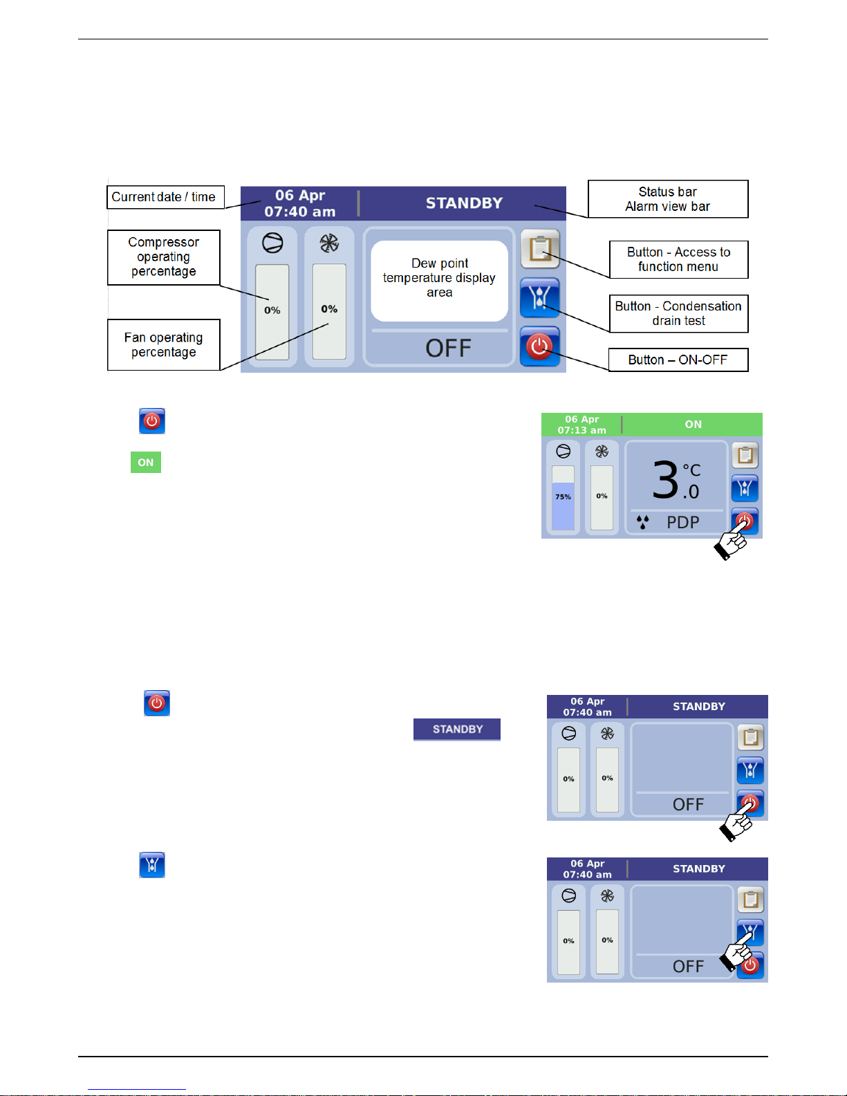
control unit initialisation process. After about 45 seconds the display will show the main screen:
0.25
8.15.1 Starting the dryer (“ON” mode)
Hold the button for 3 seconds to start the dryer.
The dryer begin the warm-up phase and the status bar will turn green and
display .
NOTE! During the warm-up phase, which lasts about 3 minutes, the
compressor works at a set speed equivalent to approximately 40-50% of its
maximum speed, to enable the lubricating oil to circulate correctly in the
compressor at the beginning. This phase is illustrated with a bar symbol under
the compressor icon, which gradually becomes blue and shows the time that
has lapsed since the dryer started. Once the dryer has warmed up the bar
symbol disappears and the dryer commences standard operation.
The display will show:
Compressor operating percentage (0-100%)
Fan operating percentage (0-100%) – Air-cooled only
Dew point temperature
Dryer status, realtime clock and data
8.15.2 Stopping the dryer (“STANDBY” mode)
Hold the button for 3 seconds to stop the dryer. The dryer will stop
(STANDBY) and the status bar will turn blue and display .
8.15.3 Performing the condensation drain test
Hold the button to perform the condensation drain test.
Release the button to finish the condensation drain test.
NOTE!
The condensation drain test can be performed at any time, regardless of the
dryer status displayed on the status bar (ON, STANDBY, ALARM, SERVICE
WARNING).
Technical description
DRYPOINT® RA 5400-10800 eco 17
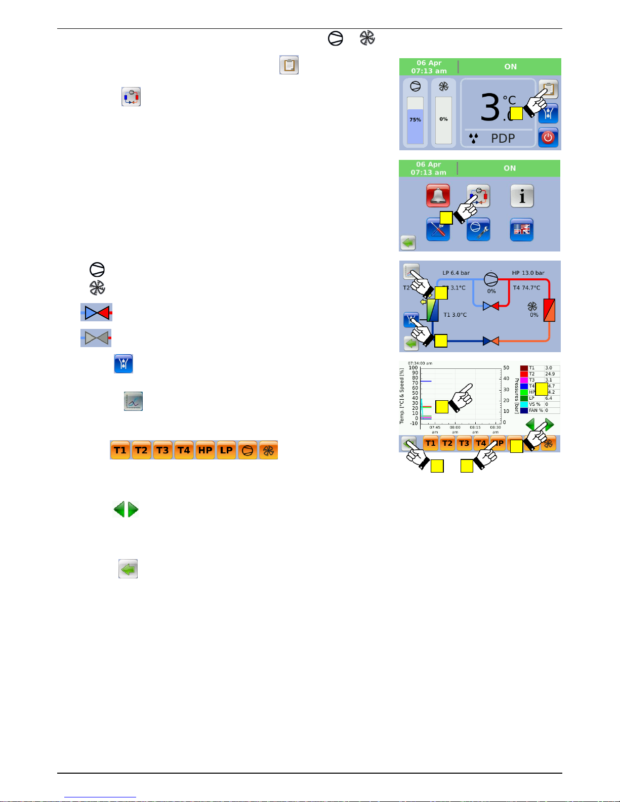
8.15.4 Displaying process values T1, T2, T3, T4, HP, LP, % , %
1- With the dryer operating (ON mode) press the button to access the
dryer's menu of functions.
2- Press the button to display the refrigeration circuit diagram and the
dryer's instantaneous process values:
➢ T1 - Value measured by the BT1 probe in °C or °F (Dew Point
temperature)
➢ T2 - Value measured by the BT2 probe in °C or °F (Air temperature at
exchanger inlet)
➢ T3 - Value measured by the BT3 probe in °C or °F (Temperature of
refrigerant gas on compressor suction side)
➢ T4 - Value measured by the BT4 probe in °C or °F (Temperature of
refrigerant gas on compressor discharge side)
➢ HP - Value measured by the BHP probe in bar or psi (Pressure of
refrigerant gas on compressor discharge side)
➢ LP - Value measured by the BLP probe in bar or psi (Pressure of
refrigerant gas on compressor suction side)
➢ % - Percentage value of compressor operation
➢ % - Percentage value of fan operation
➢ - Pressure balancing solenoid valve active (powered)
➢ - Pressure balancing solenoid valve not active (not powered)
3- Hold the button to perform the condensation drain test.
Release the button to finish the condensation drain test.
4- Press the button to display the log file process values expressed
graphically or numerically for the last 60 minutes of dryer operation. The
default graph includes traces for all 8 process values.
5- Use the buttons to display/hide the
corresponding coloured traces.
6- Touch the graph on the screen to position the cursor roughly near the
required time.
7- Use the buttons to fine tune the position of the graph cursor on the
required time. Positioning accuracy is +/- 1 minute.
8- The table on the right of the screen displays the process values stored in
the time period selected by the graph cursor in numerical format.
9- Press the button to return to the previous screen.
NOTE! The stored process values, which are available in numerical or graph
format, relate to the last 60 minutes of dryer operation. Stored process values
that are not within this time frame are permanently deleted automatically.
1-
2-
4-
3-
5-
9-
6-
8-
7-
 Loading...