

Page 1
APARAT DE AER
PERETE MANUAL DE
UTILIZARE
BXEU 090/BXEU 091
BXEU 120/BXEU 121
BXEU 180/BXEU 181
BXEU 240/BXEU 241
0010565368
Page 2

Page 3
ţ
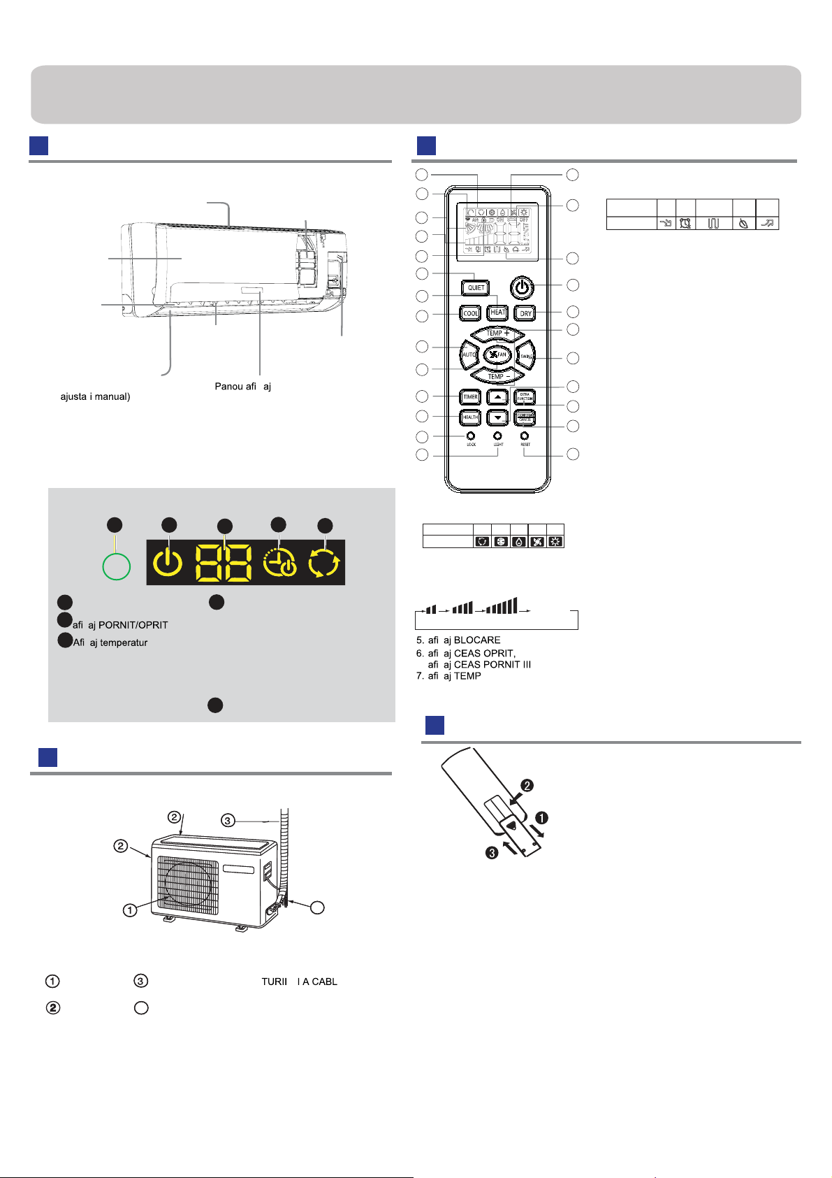
Componente şi funcţii
Unitate interioară
Filtru purificare aer
Admisie
Grilaj admisie
Evacuare
Lamelă verticală
(ajustare flux de
aer stânga şişi
Lamelă orizontală.
(ajustare flux de aer sus şi jos. Nu
ţ
Vă rugăm pe baza ofertei de achiziţionare a produsului actual, imaginea de
mai sus este doar de referinţă.
dreapta)
Panou afişaj
1
1
Gol recepţionare semnal
2
ş
3
ş
În momentul recepţionării semnalului
telecomenzii, afişajul cu setarea temperaturii,
şi în timpul de odihnă temperatura camerei
este afişată aceasta fiind doar de referinţă.
2
ă ambientală
3
Afişaj funcţie TIMER ON\OFF,
4
afişaj funcţie TIMER ON-OFF,
afiş
Reţineţi revenirea energiei electrice:
apăsaţi pe butonul funcţiei sleep de zece ori în timp de
cinci secunde şi introduceţi funcţia după ce auziţi patru
sunete. Apăsaţi pe butonul funcţiei sleep de zece ori în
timp de cinci secunde pentru a părăsi această funcţie după
ce auzi
afişaj RĂCIRE/ÎNCĂLZIRE/DEUMIDIFCARE/AUTO
5
4
aj funcţie SLEEP
i două sunete.
(interior)
Comutator de
urgenţă
5
Telecomandă
1
2
3
4
5
9
10
11
12
13
14
15
16
17
1. Afişarea modului
DEUMIDIF
RĂCIRE
Mod de operare
Telecomandă
2. Afişaj trimitere semnal
3. Afişaj OSCILARE
4. Afiş
LO MED HI
Funcţia Health nu este disponibilă în unele produse.
AUTO
ICARE
aj VITEZĂ VENTILATOR
ş
ş
ş
ş
VENTILARE
Afişaj
cir
AUTO
ÎNCĂL
ZIRE
culant
6
8. Afisaj funcţii suplimentare
7
Mod de operare
Telecomandă
9. buton funcţie QUIET
8
10. buton funcţie ÎNCĂLZIRE
11. buton funcţie RĂCIRE:
18
12. buton funcţie AUTO
13. buton VITEZĂ VENTILATOR
19
14. buton funcţie TIMER
15. buton funcţie HEALTH
20
16. buton BLOCARE
Utilizat pentru blocarea butoanelor şi
21
afişajului LCD
17. buton funcţie LIGHT
Controlează aprinderea şi oprirea panoului
22
afişajului LED a unităţii interioare.
18. buton ALIMENTARE PORNIT/OPRIT
23
19. buton DEUMIDIFICARE
24
20. buton TEMPERATURĂ
21. buton funcţie OSCILARE
22. buton ORĂ
25
23. buton FUNCTIE SUPLIMENTARE
Funcţie: Sleep→Poziţia fluxului de
aer→Poziţia fluxului de aer 2 →
→Furnizare aer →Limitat A-B
24.buton ANULARE/CONFIRMARE
Funcţie: Setarea şi anularea temporizatorului şi a
altor funcţii suplimentare. III
25. buton RESETARE
În momentul în care telecomanda nu funcţionează
normal, utilizaţi un obiect cu vârf ascuţit pentru a
apăsa acest buton pentru a reseta telecomanda.
QUIET
SLEEP
încălzire
electrică
suplimentată
HEALTH
TURBO
Unitate exterioară
4
EVACUARE
ADMISIE
Vă rugăm pe baza ofertei de achiziţionare a produsului actual, imaginea de
mai sus este doar de referinţă.
CONECTAREA TUBULA ĂRII
FURTUN DE EVACUARE
4
Încărcarea bateriei
1 Scoateţi capacul bateriei;
2 Introduceţi bateriile după cum este ilustrat.
2 baterii R-03, cheie de resetare (cilindru);
3 Asiguraţi-vă că încărcarea este
conformă semnelor " + "/"-";
4 Introduceţi bateria, apoi puneţi capacul din nou.
Reţineţi:
• Distanţa dintre capul de transmitere a semnalului şi receptorului treb
7m fără niciun obstacol.
• În momentul în care lămpile fluorescente cu pornire electronică sau telefonul
fără fir sunt instalate în cameră, receptorul este apt pentru a fi deranjat din
recepţionarea semnalelor, iar distanţa la unitatea interioară trebuie să fie mai
mică.
• AfişŞaj complet sau afişaj neclar în timpul funcţionării indică că bateriile
au fost utilizate complet. Vă rugăm încărcaţi bateriile.
• Dacă telecomanda nu poate funcţiona normal, vă rugăm să scoateţi bateriile şi
să reluaţi procesul câteva minute mai târziu.
Sfat:
În cazul în care aparatul nu va fi folosit pentru o perioadă îndelungată de timp,
scoateţi bateriile Dacă există vreo afişare după scoaterea acestora, apăsaţi butonul
de resetare.
uie să
1
Page 4
Funcţionare
Operaţii de bază
Telecomandă
2
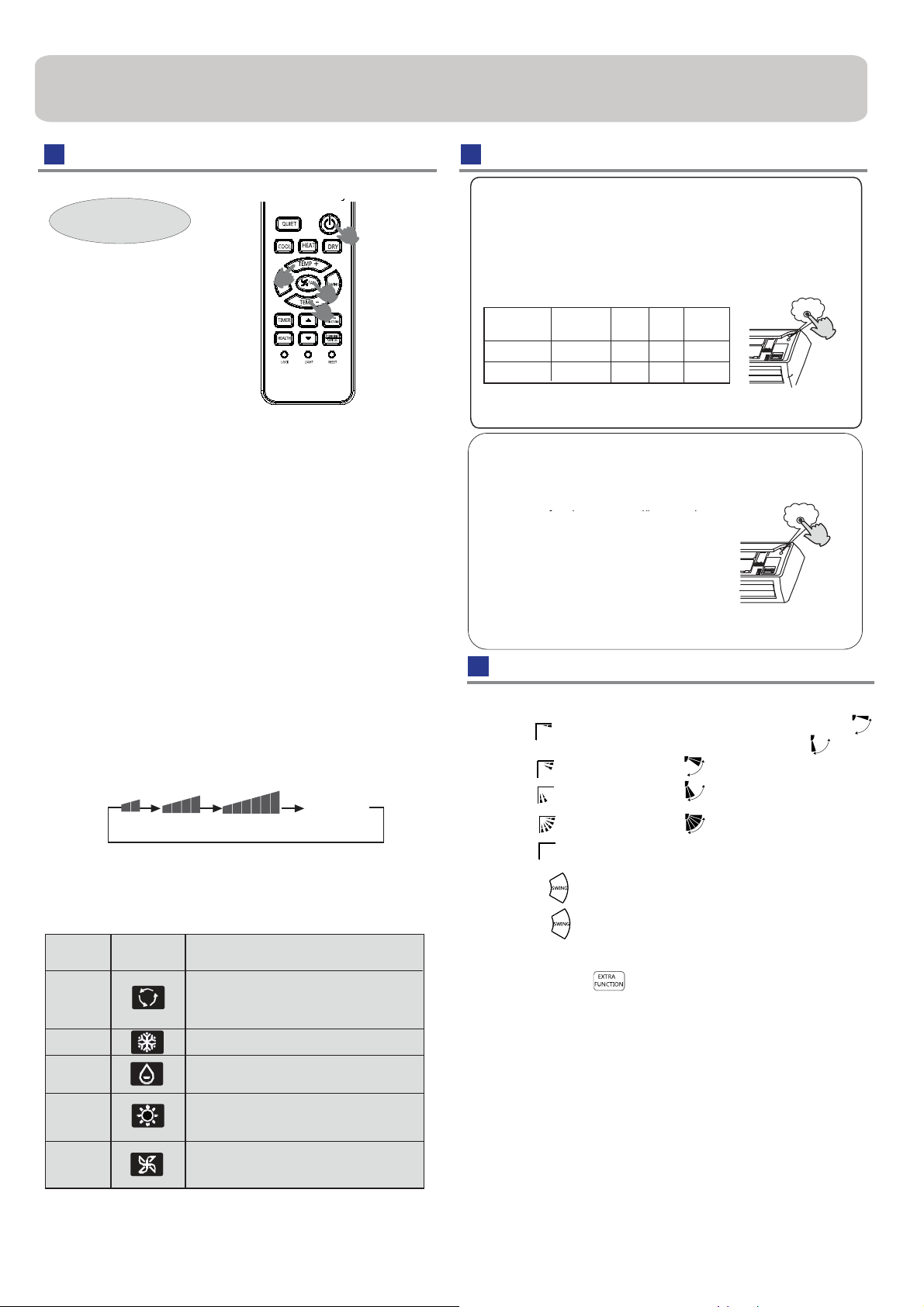
1. Aparatul porneşte.
Apăsaţi butonul PORNIT/OPRIT de pe telecomandă,
aparatul porneşte.
2. Selectaţi modului de funcţionare
buton funcţie RĂCIRE: Mod răcire
buton funcţie ÎNCĂLZIRE: Mod funcţie încălzire
buton DEUMIDIFICARE: Mod deumidificare
3.Selectaţi setarea de temperatură
Apăsaţi
TEMP+ De fiecare dată când butonul este apăsat, setarea de
BUTONUL temp+/temp-
temperatură creşte cu 1°C, dacă nu este
apăsat, acesta va creşte rapid
TEMP- De fiecare dată când butonul este apăsat, setarea de
temperatură scade cu 1°C, dacă nu este menţinut
apăsat, acesta va scade rapid. Selectaţi o
temperatură dorită
4. Selectarea vitezei ventilatorului
Apăsaţi butonul VENTILARE. Pentru fiecare apăsare,
viteza ventilatorului se schimbă după cum urmează:
Telecomandă
LO MED HI
Aparatul de aer condiţionat funcţionează la viteză
ventilatorului afişată. În momentul când modul VENTILARE
este setat la AUTO, aerul condiţionat ajustează
viteza ventilatorului conform temperaturii camerei.
Mod de
operare
AUTO
RĂCIRE
DEUMIDI
FICARE
ÎNCĂLZIRE
VENTILARE
Telecomandă
În acest mod de funcţionare automată, aparatul de aer condiţionat
va selecta automat funcţionarea modului RĂCIRE sau
ÎNCĂLZIRE conform temperaturii camerei. În momentul când
modul VENTILARE este setat la AUTO, aerul condiţionat
ajustează automat viteza ventilatorului conform temperaturii
camerei.
În modul DEUMIDIFICARE, atunci când temperatura camerei
scade sub temperatura setată de +2°C, aparatul va funcţiona
intermitent la o viteză SCĂZUTĂ indiferent d
VENTILARE.
În modul ÎNCĂLZIRE, aerul cald va fi suflat după o perioadă scurtă
de timp datorită funcţiei de prevenire. În momentul când modul
VENTILARE este setat la AUTO, aparatul de aerul condi ţionat
ajustează automat viteza ventilatorului conform temperaturii
camerei.
În modul de funcţionare VENTILARE, aparatul nu va funcţiona în
modul RĂCIRE sau ÎNCĂLZIRE, dar va funcţiona numai în modul
VENTILARE, setarea AUTO nefiind disponibilă în modul
VENTILARE. Şi setarea de temperatură este deza
VENTILARE, funcţionarea modului sleep nu este disponibilă
Reţine
2
1
3
2
menţinut
Afişaj
circulant
AUTO
automat
e setarea modului
ctivată. În modul
Funcţionarea de urgenţă şi operarea test
Funcţionare de urgenţă:
• Utilizaţi această funcţie în momentul când telecomanda este defectă sau
pierdută, şi prin această funcţie, aparatul de aerul condiţionat poate funcţiona
automat pentru o perioada de timp.
• În momentul când comutatorul pentru funcţionarea de urgenţă este apăsat,
sunetul "Pi" este auzit doar o singură dată, ce înseamnă pornirea acestei
funcţii.
• În momentul când comutatorul este rotit pentru prima dată şi funcţionarea de
urgenţă
porneşte, aparatul va funcţiona automat în următoarele moduri:
Temperatura
camerei
Peste 23
Sub 23
• Este imposibil să schimbaţi setarea temperaturii, şi a vitezei ventilatorului, de
asemenea, nu este posibilă funcţionarea în modul timer sau modul
deumidificare.
Temperatură
dorită
o
C
26
o
C 23oC
Mod
Viteză
ventilator
Timer
o
Nu
C AUTO
AUTO
Nu
Mod de
operare
RĂCIRE
ÎNCĂLZIRE
Pi
Operare de testare:
Comutatorul operare de testare este asemenea comutatorului
de urgenţă.
• Utilizaţi acest comutator în faza de testare a aparatului în
momentul când temperatura camerei este sub 16°C, nu utilizaţi
• Continuaţi să apăsaţi comutatorul pentru mai
mult de 5 secunde. După ce auziţi sunetul "Pi"
de două ori, eliberaţi comutatorul, funcţia de
răcire porneşte având o viteză a fluxului de aer
"Hi".
• Sub acest mod de funcţionare, motorul ventilatorului
unităţii interioare va funcţiona la o viteză ridicată.
Pi Pi
Reglarea direcţiei fluxului de aer
1 .Lamelă verticală Telecomandă
Poz.1
Poz.2
Poz.3
Poz.4
(Oscilare automată)
Poz. 5
2.Apăsaţi
butonul, se schimbă după cum urmează: Poz.4
Apăsaţi butonul din nou. Lamela verticală se va opri în
poziţia prezentă, funcţia de oscilare va fi anulată.
3.Apăsaţi butonul pentru a alege Poz 2 şi Poz. 3.
4.Reglările fluxului de aer către stânga şi dreapta(manual) Mişcaţi
lamela verticală prin intermediul unui buton de pe aparatul de aer
condiţionat pentru a ajusta direcţia către stânga şi dreapta făcând
referire la Fig.
• În momentul când ajustaţi lamela manual, închideţi aparatul.
• Când umiditatea este ridicată, apa condensată poate apărea reglate
în partea stângă sau la eva
sunt drepte.
• Este sfătuitor să nu menţineţi lamela orizontală într-o poziţie
descendentă pentru o durata mare de timp în modul RĂCIRE sau
DEUMIDIFACARE, datorită acestui lucru apa condensată poate
apărea.
Reţineţi:
În momentul când reporniţi aparatul după oprirea din telecomandă,
telecomanda va memora automat poziţia anterioară de oscilare.
RĂCIRE/OTWMOnWItHisfeteiite):
ÎNCĂLZIRE1K(htftib±tate)e):
cuarea aerului dacă fantele verticale
Page 5
Funcţionare
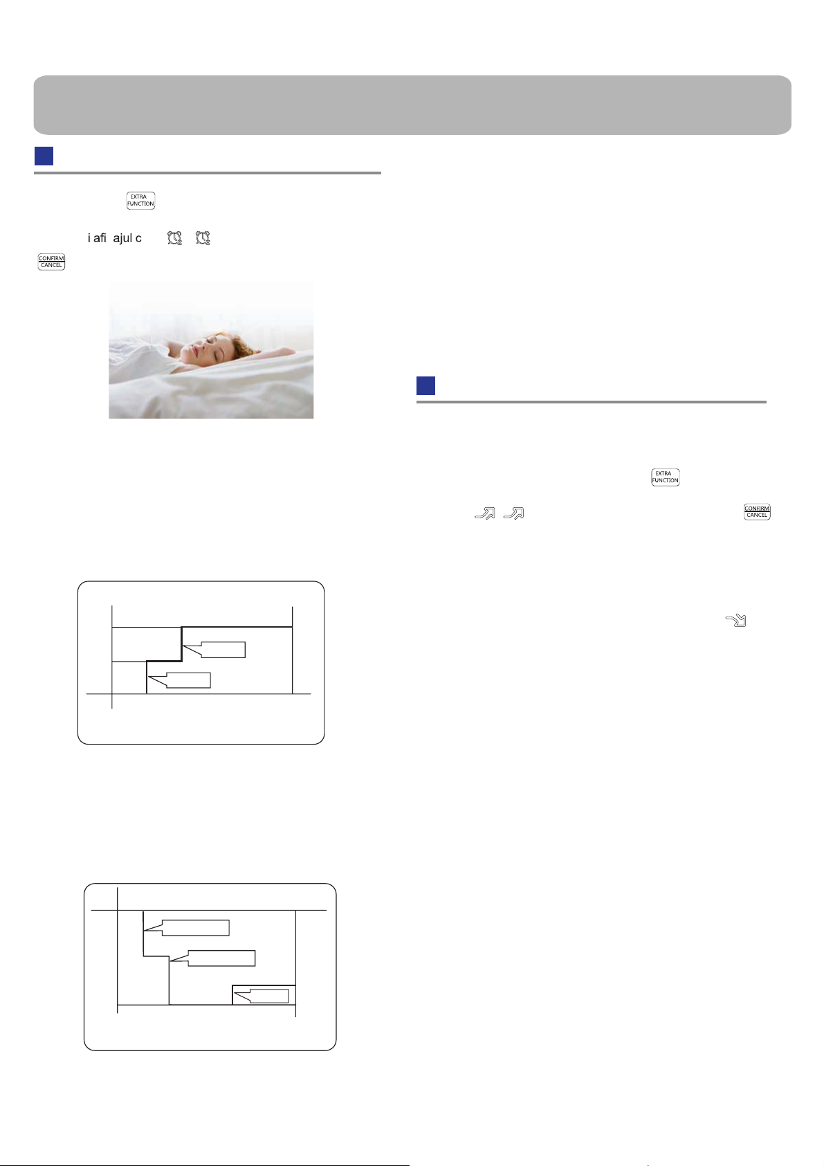
Funcţionarea modului sleep
Apăsaţi butonul pentru a introduce opţiuni suplimentare,
în momentul în care
succedeţ
pentru a intra în funcţia sleep.
ătre , acesta va clipi. Şi apoi apăsaţi
ş
4. În modul VENTILARE
Nu are funcţia SLEEP.
5.Setaţi schimbarea vitezei fluxului de aer în momentul când
dormiţi. Dacă viteza fluxului de aer este ridicată sau la mijloc
înainte de setarea pentru funcţia sleep, setaţi pentru scăderea
vitezei fluxului de aer după funcţia odihnă. Dacă este un flux de
aer slab, nu-l schimbaţi
Reţine
În momentul în care funcţia TIMER este setată, funcţia sleep nu
poate fi setată. După ce funcţia sleep este setată, dacă utilizatorul
resetează funcţia TIMER, funcţia sleep se va anula, aparatul va fi
in starea de cronometrare.
Funcţionarea modului POWER/QUIET
Mod de operare
1. În modul RĂCIRE. DEUMIDIFICARE
1 oră după ce funcţia modulului SLEEP porneşte, temperatura va
creşte cu 1°C decât setarea de temperatură.După o altă oră,
temperatura creşte cu încă 1°C. Aparatul va funcţiona timp de 6
ore şi apoi se opreşte. Temperatura este mai crescută decât
setarea temperaturii pentru ca temperatura camerei să nu fie prea
coborâtă pentru somnul dvs.
funcţia SLEEP porneşte funcţia SLEEP se opreşte
Aprox.6 ore
1 hr
1 hr
Setare temperatură
În modul RĂCIRE, DEUMIDIFICARE
Creşte 1°C
Creşte 1°C
Aparatul se opreşte
2. În modul ÎNCĂLZIRE
1 oră după ce funcţia modului SLEEP porneşte, temperatura va fi
mai coborâtă cu 2°C decât setarea temperaturii. După o al
tă oră
temperatura va scădea cu încă 2°C.După 3 ore, temperatura va
creşte cu 1°C. Aparatul va
funcţiona timp de 3 ore, şi apoi se
opreşte. Temperatura este mai coborâtă decât setarea
temperaturii, iar temperatura camerei nu va fi prea ridicată pentru
somnul dvs.
Setare temperatură
Aparatul se opreşte
(1) Funcţionarea modului POWER
În momentul când doriţi o încălzire sau răcire rapidă, puteţi
utiliza aceasta funcţie. Apăsaţi butonul pentru a
introduce opţiuni suplimentare, atunci când afişajul se succede
pentru acesta va clipi, şi apoi apăsaţi butonul
pentru a intra în functia de putere. În momentul când anulaţi
această funcţie, vă rugăm să introduceţi opţi
unile suplimentare
încă o dată şi apoi să anulaţi funcţia de putere
(2) Funcţionarea modului QUIET
Puteţi utiliza aceasta funcţie în momentul în care vă odihniţi sau citiţi.
Apăsaţi butonul meniului QUIET, telecomanda va afişa şi apoi
realizează funcţia modulului. Apăsaţi din nou butonul funcţiei QUIET,
aceasta funcţie va fi anulată.
Reţineţi:
În timpul funcţionării modului POWER, aflată în modul rapid
ÎNCĂLZIRE sau RĂCIRE, camera va prezenta o distribuţie a
temperaturii neomogenă. Funcţionarea modului QUIET pe termen
lung va cauza efectul de a nu fi prea rece sau prea ca
ld.
1 hr
Scade 2°C
Scade 2°C
3 ore
3 ore
Creşte 1°C
funcţia SLEEP se
opreşte
1 hr
funcţia SLEEP
porneşte
În modul ÎNCĂLZIRE
3. În modul AUTO
Această unitate funcţionează în modul SLEEP corespunzător
adaptat modului de funcţionare selectat automat.
3
Page 6
Funcţionare
REGLEMENTĂRILE EUROPENE CU
PRIVIRE LA MODELE
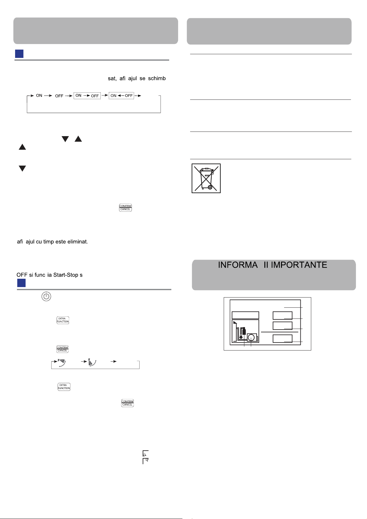
Funcţionarea funcţiei Timer On/Off On-Off
1.După pornirea aparatului, selectaţi modul de funcţionare dorit.
2.Apăsaţi butonul TIMER pentru a schimba modu
fiecare dată când butonul este apă
l TIMER. De
ă
după cum urmează: Telecomandă:
LIBER
0.5h
CEAS PORNIT TEMPORIZATOR
0.5h 0.5h
CEAS OPRIT
PORNIT-OPRIT
0.5h
TIMER OFF-ON
Apoi selectaţi modul TIMER dorit (TIMER PORNIT sau TIMER
OPRIT sau TIMER PORNIT-OPRIT). "
PORNİT "sau" OPRİT "va clipi.
3.Apăsaţi butonul / pentru a seta ceasul.
Apăsaţi butonul de fiecare dată, setarea ceasului în primele 12
ore creşşte cu 0.5 ore de fiecare dată, după 12 ore aceasta creşte cu
1 oră de fiecare dată.
Apăsaţi butonul de fiecare dată, setarea ceasului în primele 12
ore scade cu 0.5 ore de fiecare dată, după 12 ore aceasta scade cu
1 oră de fiecare dată. III
Poate fi ajustat în limitele celor 24 de ore.
Confirmaţi setarea ceasului
4.
După ajustarea ceasului, apăsaţţi butonul şi confirmaţi timpul
prin intermediului butonului PORNIT sau OPRIT, acesta nu va mai
clipi.
5.Anulaţi setarea ceasului
Apăsaţi butonul ceasului de câte ori este necesar până când
ş
Sfaturi:
După înlocuirea bateriilor sau producerea unei pene de curent,
setarea ceasului ar trebui fi resetată.
Conform setării ceasului fiecare secvenţa de TIMER ON sau TIMER
au Stop-Start poate fi atinsă.
Funcţionarea fluxului de aer
CE
Toate produsele sunt conforme cu următoarele prevederi
europene:
- Directiva privind voltajul redus 73/23/EEC
- Directiva privind voltajul redus 2006/95/EC
- Directiva privind compatibilitatea electromagnetică 89/336/EEC
- Directiva privind compatibilitatea electromagnetică 2004/108/EC
ROHS
Produsele respectă cerinţele directivei 2002/95/EEC a
Parlamentului European şi a Consiliului de restricţia în utilizare a
anumitor substanţe peric
uloase la echipamentele electrice şi
electronice (Directiva UE RoHS)
WEEE
În conformitate cu directiva 2002/96/CE a Parlamentului European,
informăm cele ce urmează consumatorii cu privire la cerinţele care
se impun la eliminarea produselor electrice şi
electronice.
CERINTE DE ELIMINARE:
Aparatul de aer condiţionat este marcat cu acest
simbol. Acesta înseamnă că produsele electrice şi
electronice nu trebuie amestecate cu deşeuri
menajere nesortate Nu încercaţi să dezasamblaţi
singur sistemul: dezasamblarea sistemului de aer
condiţionat, tratarea refrigerantului, a uleiului şi
ale
altor componente trebuie efectuată de către un instalator calificat în
conformitate cu legislaţia locală şi naţională. Aparatele de aer
condiţionat trebuie tratate la o fabrica specializată pentru reutilizare,
reciclare şi recuperare. Prin asigurarea eliminării acestui produs
corect, veţi preveni potenţiale consecinţe negative asupra mediului
înconjurător şi stării generale de sănătate. Pentru mai multe
informaţii, vă rugăm contactaţi instalatorul sau autoritatea locală.
Bateria trebuie scoasă din telecomandă şi eliminată separat
m legislaţiei locale şi naţionale în vigoare.
confor
Ţ
REFERITOARE LA AGENTUL
REFRIGERENT UTILIZAT
1.Apăsaţi pentru pornire
Setarea condiţiilor de lucru confortabile.
2.Setarea funcţionarii fluxului de aer
Apăsaţi butonul pentru a introduce opţiuni suplimentare.
Apăsaţi acest
buton continuu, locaţia grilajului se va succede între următoarele trei
locaţii, pentru alegerea locaţiei de oscilare care aveţi nevoie, şi apoi
apăsaţi butonul pentru confirmare.
Flux de aer
ascendent
Flux de aer
descendent
Poziţia
prezentă
3.Pentru a anula funcţia fluxului de aer
Apăsaţi butonul pentru a introduce opţiuni suplimentare.
Apăsaţi butonul continuu, fantele se vor succeda între
trei locaţii din nou, şi apoi apăsaţi butonul pentru anu
următoarele
lare.
Atenţie: Nu dirijaţi manual lamelele. În caz contrar, fanta va
funcţiona incorect. Dacă fanta nu funcţionează corect, opriţi
aparatul timp de un minut şi apoi porniţi-l din nou, reglând aceasta
prin intermediul telecomenzii.
Reţineţi:
1.După setarea funcţiei fluxului de aer, poziţia fantei este fixă.
2.Pentru căldură. este mai bine să selectaţi modul
3.Pentru răcire, este mai bine să selectaţi modul
4.În modul de răcire şi deumidificare, utilizând un aparat de aer
pentru o perioadă lungă de timp sub umiditate ridicat
condensată poate apărea pe fantă.
ă a aerului, apa
Conţin gaze de seră fluoroniate aprobate de către
Protocolul Kyoto.
R410A
2
1
F E
1=
2=
1+2=
kg
kg
kg
A
B
C
D
Acest produs conţine gaze de seră fluorinate aprobate de către
Protocolul Kyoto. Nu le eliberaţi în atmosfera. Tip refrigerent:R410A
Valoare GWP* 1975
GWP = potenţial de încălzire global
Vă rugăm completaţi cu cerneala neradiabilă,
• 1 cantitatea de refrigerent din fabrica a produsului
• 2 cantitatea de refrigerent adăugată suplimentar în teren şi
• 1 +2 cantitatea totală de refrigerant
pe eticheta de încărcare a refrigerentului furnizată împreună cu
produsul.
Eticheta completată trebuie păstrată în vecinătatea
portului de
încărcare a produsului (ex. pe interiorul capacului supapei de
închidere).
A Acest produs conţine gaze de seră fluorinate aprobate de către
Protocolul Kyoto.
B cantitatea de refrigerent din fabrică a produsului: a se vedea
eticheta tehnică
C cantitatea de refrigerent adăugată în teren
D cantitatea totala de refrigerent
E unitatea exterioară
F cilindrul refrigerantului şi distribuitor pentru încărcare
4
Page 7
Montarea aparatului în interior
Unelte necesare pentru montaj
• Şurubelniţă
• Cleşte
• Bomfaier
• Bormaşină cu carotieră
• Cheie de piuliţe (17,19 şi 26mm)
• Detector de gaze sau soluţie apă
şi săpun
Selectarea locului pentru montaj
• Cheie dinamomentrică
(17mm,22mm,26mm)
• Dispozitiv de tăiat ţevi
• Dispozitiv de lărgit ţevi
• Cuţit
• Ruletă
• Alezor
• Înainte de a introduce în priză, verificaţi tensiunea
• Tensiunea de alimentare este corespunzătoare etichetei tehnice
• Montaţi un circuit derivat exclusiv
• Priza trebuie să fie amplasată la distanţă unde cablul de alimentare
poate fi ajuns. Nu prelungiţi cablul prin tăierea acestuia.
Sursa de alimentare
Piese auxiliare
• Locul, robust necauzator de vibraţii, unde corpul poate fi
suportat suficient.
• Locul, neafectat de căldură sau aburul degajat în vecinătate,
unde admisia şi evacuarea produsului nu este întreruptă.
• Locul, pentru a se drena uşor, unde conductele pot fi
conectate la unitatea exterioară.
• Poziţionaţi, unde aerul rece poate fi răspândit complet într-o
încăpere.
• Poziţionaţi, lângâ o prizâ, având destul spaţiu
• Poziţionaţi unde o distanţă mai mare de 1m de la televizoare,
radiouri, aparaturi fără fir şi lămpi fluorescente poate fi lăsată.
• În cazul poziţionării telecomenzii pe perete, poziţionaţi aceasta
unde unitatea interioară poate primi semnale în momentul
cănd lămpile fluorescente din camera sunt aprinse.
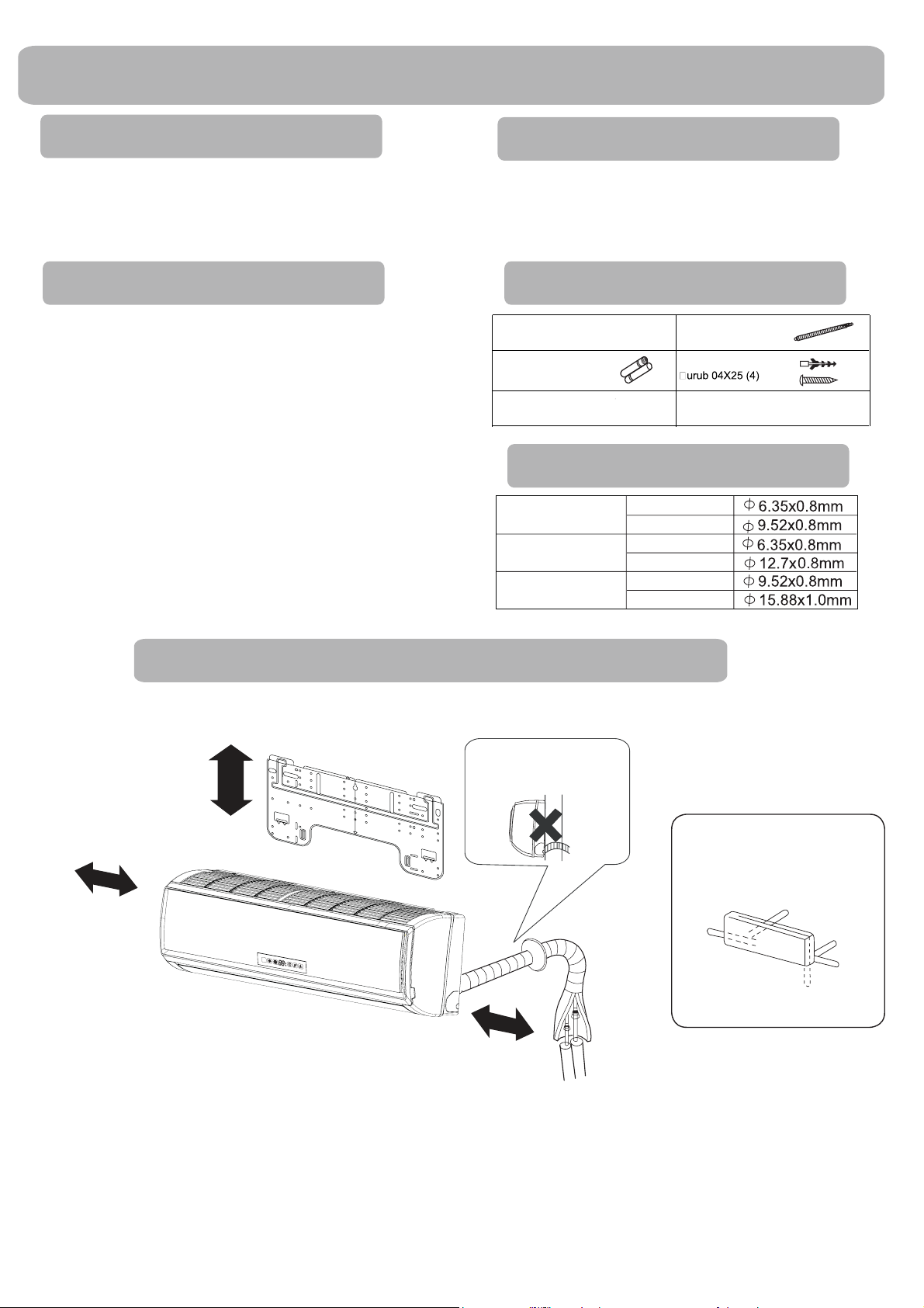
Pozarea montajului unităţilor interioare
Modelele adopta refrigerant HFC de tip R410A
mai mult de 15 cm
Telecomandă (1) Furtun evacuare (1)
Baterie uscată R-03
Placă de montaj (1)
(2)
Capac plastic (4)
Filtru purificator de aer(Optional) (1)
Selectarea conductelor
PENTRU 07K 09K 12K
PENTRU 18K
PENTRU 24K
Atenţia trebuie să fie prezentă
în momentul ridicării furtunului
de evacuare
Conductă de apă
Conductă de gaz
Conductă de apă
Conductă de gaz
Conductă de apă
Conductă de gaz
mai mult de
10cm
mai mult de 10crr
Distanţa dintre unitatea interioară şi pardoseală trebuie să fie mai mare de 2m.
Vă rugăm pe baza ofertei de achiziţionare a produsului actual, imaginea de mai sus este
Aranjamentul direcţiilor
conductelor
Spate stânga
Stânga
doar de referinţă.
Spate
dreapta
Dreapta
Sub
5
Page 8
Montarea aparatului în interior
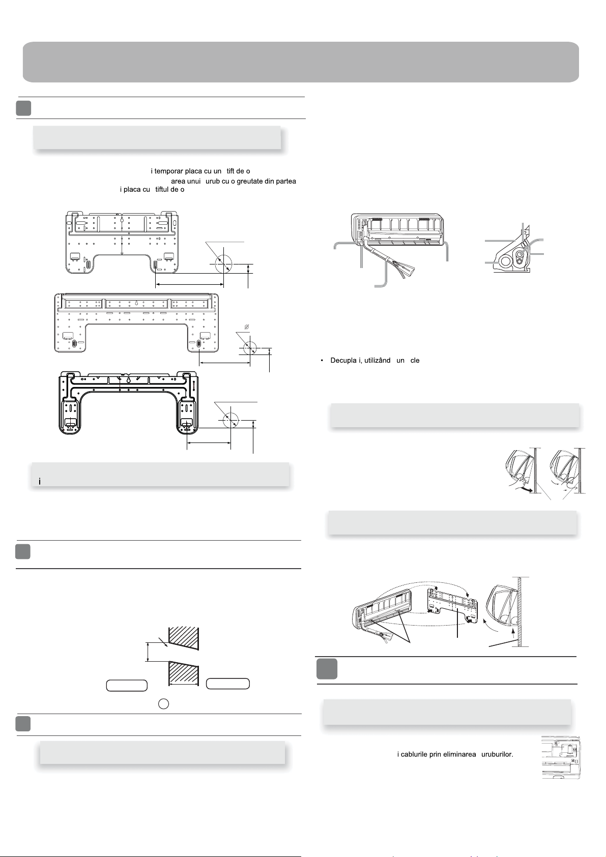
1
Ajustarea plăcii de montaj şi poziţionarea găurii din perete
În momentul când placa de montaj este prima fixată
1. Efectuaţi, bazându-vă pe stâlpii învecinaţi sau buiandrugi, o echilibrare bună a plăcii
pentru a fi fixată in perete, apoi strângeţ
2. Asiguraţi-vă încă o dată nivelul plăcii, prin agăţ
centrală a plăcii, apoi strângeţ ţel anexat..
3. Găsiţi locaţia găurii de perete A utilizând o ruletă
ş
A=145mm
ş
Ø
B=
A=150mm
B=
ş
70mm
B= 70mm
Ø
70mm
ţel.
30mm
35mm
[ Stânga • Conducte spate stânga ]
• În cazul conductelor de pe partea stânga, tăiaţi cu un cleşte, capacul pentru
conductele de pe partea stângă.
• În cazul conductelor spate stânga, îndoiţi conductele conform direcţiei acestora
pentru a marca gaura pentru conductele spate stânga care sunt marcate pe
materialele de termoizolaţie.
1. Introduceti furtunul de evacuare în interiorul semnului
termoizolante ale unităţilor interioare.
2. Introduceti cablul electric interior/exterior din spatele unităţilor de interior, şi
trageţi-l prin partea frontală, apoi conectaţi-l.
3. Acoperiţi faţa garniturii de lărgire cu ulei refrigerent şi conectaţi conductele.
Acoperiţi conexiunea cu materiale termoizolante, şi asiguraţi fixarea cu banda
adezivă
Cablu electric interior/exterior
Material
termoizolant
Capac pentru conductele
de pe partea dreaptă
Capac pentru conducte.
Fixaţi-l cu bandă adezivă
• Cablul electric interior/exterior împreună cu furtunul de evacuare trebuie să fie
legate de către conductele de refrigerare cu bandă de protecţie.
Capac pentru
conductele de pe
partea stângă
evacuare
materialelor
Placa care suporta
conductele
Conducte
[ Altă direcţie a conductelor ]
conductei şi îndoiţţi conducta conform poziţiei găurii de perete. În momentul
îndoirii, asiguraţi-vă că nu crăpaţi conductele.
• Conectaţi în prealabil cablul electric interior/exterior, şi apoi trageţi cablul către
termoizolaţia componentei conectate.
şte, capacul conductelor conform direcţiei
A=145mm
30mm
În momentul când placa de montaj este fixată de bara alăturată
ş
buiandrug.
• Fixaţi de buiandrug o bară de montaj, care este separată vândută, şi apoi strângeţi placa
pe bara de montaj fixată
• Reveniţi la articolul anterior," În momentul când placa de montaj este fixată prima ",
pentru poziţia găurii de perete.
2
Crearea unei găuri în perete şi fixarea unui capac al golului
conductei.
• Creaţi o gaură având un diametru de 70 mm, având un caracter descendent către
exteriorul peretelui.
• Montaţi capacul de acoperire a găurii pentru conducte şi sigilaţi aceasta cu chit după
montare.
Montarea unităţii interioare
3
Gaură de perete
Ø70mm
Partea interioară
(Secţiunea găurii peretelui)
Grosimea peretelui
G
Gol pentru conducte
Partea exterioară
Fixarea corpului unităţii interioare
• Agătaţi corpul unităţii peste crestături superioare ale plăcii de
montaj. Mişcaţi corpul dintr-o parte în alta pentru a verifica
fixarea în siguranţă.
• Pentru a fixa corpul pe placa de montaj, ţineţi corpul
înclinat de partea inferioară şi plasaţi-l perpendicular.
Descărcarea corpului unităţii
• În momentul când descărcaţi unitatea interioară, vă rugăm să vă utilizaţi
mâinile pentru a ridica corpului pentru a lăsa agrafele,
inferioară a corpului numai puţin şi ridicaţi unitatea înclinată până când
aceasta părăseşşte placa de montaj.
placă de montaj
interioare
apoi ridicaţi din partea
agrafă
4
Conectarea cablului electric interior/exterior
placă de montaj
Scoaterea protecţiei pentru fire
Pozarea conductelor
[ Conducte spate ]
• Pozaţi conductele si furtunul de evacuare, apoi strângeţi-le cu banda adezivă
6
• Eliminaţi capacul terminal de la colţul jos dreapta al unităţii
interioare, apoi scoateţ
Page 9
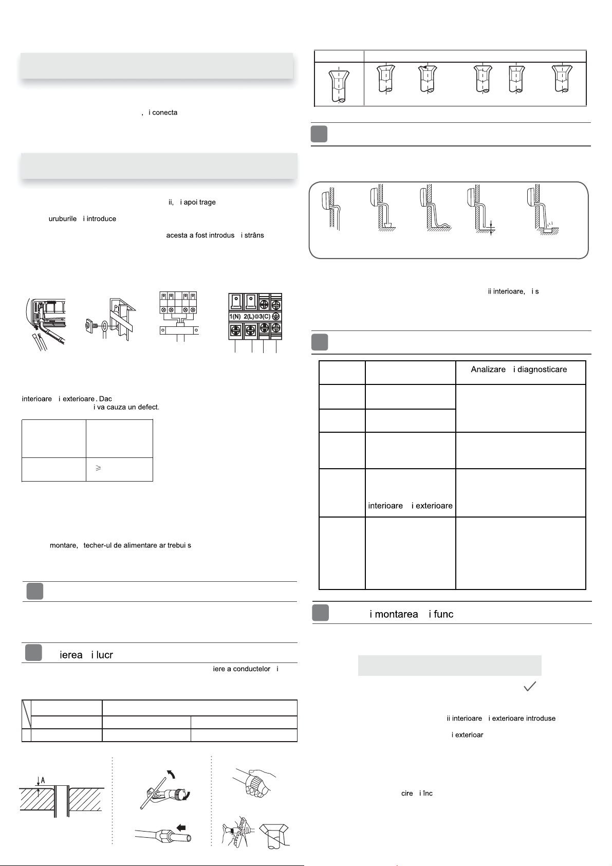
În momentul conectării cablului după montarea unităţii
interioare
Corect Incorect
1. Introduceţi dinspre exteriorul camerei, cablul în partea stângă a găurii de
perete, unde conducte se află deja.
2. Trageţi cablul prin partea frontală
ş
ţi cablul creând o bucla.
În momentul conectării cablului înainte de montarea unităţii
interioare
• Introduceţi cablul din partea din spate a unităţ ţi cablul spre partea
frontală.
• Slăbiţi ş ţi complet capătul cablului în blocul terminalului, apoi
strângeţi şuruburile.
• Trageţi uşor de cablu pentru a vă asigura că
corespunzător.
• După conectarea cablului, nu uitaţi să strângeţi cablul conectat cu acoperirea pentru
cablu.
ş
ş
ş
Unitate interioară
Pentru unitatea
exterioară
Reţineţi:
În momentul conectării cablului, confirmaţi cu grijă numărul terminalului unităţilor
nu poate fi efectuată
1. Dacă cablul de alimentare este deteriorat, acesta trebuie înlocuit de către producător
2. Dacă siguranţa de pe placa PC este arsă, vă rugăm să o schimbaţi cu
3. Metoda de cablare ar trebui să fie conform standardului local de cablare.
4. După
5. Un întrerupător ar trebui fi încorporat în cablarea fixă. Întrerupătorul ar trebui să fie un
• Sursa de alimentare trebuie să fie utilizată doar pentru aparatul de aer condiţionat.
• În cazul montării unui aparat de aer condiţionat într-un loc umed, vă rugăm să montaţi un
• Pentru montajul în alte locuri, utilizaţi un întrerupător pe cât posibil.
• Tăierea conductei este efectuată de către dispozitivul de tă
operaţiunea de bavurare trebuie efectuată • După introducerea piuliţei de racord,
operaţiunea de lărgire este efectuată
A
ş
Model
Conectarea
cablurilor
sau de către agentul de service sau o persoană calificată similar. Tipul cablului de
conectare este H05RN-F sau H07RN-F.
siguranţă de tipul T.3.15A/250VAC (Interior).
ş
întrerupător cu poli compleţi, iar distanţa dintre cele două borne nu trebuie să fie mai
mică de 3mm.
5
Montarea sursei de alimentare
întrerupător cu împământare.
6
Tă ările de lărgire ale conductelor
ă cablarea este incorectă, funcţionarea corespunzătoare
ş
BXEU 090/BXEU 091
BXEU 120/BXEU 121
BXEU 180/BXEU 181
BXEU 240/BXEU 241
4G0.75mm
2
ă fie ajuns cu uşurinţă.
ş
ş
Unealtă de lărgire
pentru R410A
Piuliţă de blocare
A 0~0.5mm 1.0~1.5mm 1.5~2.0mm
Matriţare unelte lărgire
Piuliţă de blocare (tip
3.Introduceţi piuliţa de racord
Unealtă de lărgire convenţională
I.Tăiaţi conducta
rigid)
Piuliţa fluture (tip imperial)
2.Debavuraţi
4.Lărgiţi conducta
Înclinare Avarierea lărgirii
Pe evacuare
7
• Vă rugăm să montaţi furtunul de evacuare încât să aibă o panta descendentă. • Vă
rugăm să nu efectuaţi dreanarea cum este descris mai jos.
Devine greu la
mijloc
Capătul este
imersat în apă.
Se
ondulează.
Crăpare parţială
Spaţiul cu
pământul este
prea mic.
Mai puţin
de 5cm
Prea în
exterior
Există un miros
urât
• Vă rugăm să turnaţi apă în tava de evacuare a unităţ ă confirmaţi
drenarea către partea exterioară.
• În cazul în care furtunul de evacuare ataşat este în camera, vă rugăm să aplicaţi
izolaţie termică pe acesta pentru a nu ceda.
Pe evacuare
8
Indicarea
Descrierea problemelor
codului
E1 Defecţiune senzor
temperatură cameră
E2
Defecţiune senzor
schimbare căldură
E4 Eroare interioară
EEPROM
E7 Defecţiune de
comunicare între
unităţile
ş
Conexiune defectă conector;
Termistor defect;
PCB defect
Date EEPROM greşite;
EEPROM greşit;
PCB defect
Unitate interioară - unitate ă
exterioară eroare transmisie
semnal datorită erorii de cablare;
PCB defect
Oprire funcţionare datorită
scurtcircuitului cablului în interior
E14 Defecţiune motor
ventilator interior
motorului ventilatorului;
Oprire funcţionare datorită
deteriorării cablurilor motorului
ventilatorului; Eroare de detectare
datorită unităţii PCB deteriorate;
9
Verificaţ ţionarea
ş
ş
ş
■ Vă rugăm să explicaţi clienţilor noştri cum să
folosească aparatul utilizând manualul de utilizare
Verificaţi elementele pentru funcţionare
□ Vă rugăm să plasaţi semne de verificare în căsuţe
□ Scăpări de gaz de la conectarea conductei?
□ Izolarea termică a conectării conductei?
□ Sunt cablurile de conectare ale unităţ
în blocul terminal?
□ Conectarea dintre unitatea interioară
□ Drenajul este efectuat în siguranţă?
□ Împământarea este conectată în siguranţă?
□ Unitatea interioară este fixată în siguranţă?
□ Este voltajul suportat de către cod?
□Exista vreun zgomot?
□ Lampa luminează normal?
□ Sunt operaţiunile de ră ălzire (în momentul pompei de căldură)
efectuate normal?
□ Este normală funcţionarea regulatorului de temperatură a camerei?
ş
ş
ş
ă este ferm efectuată?
7
Page 10
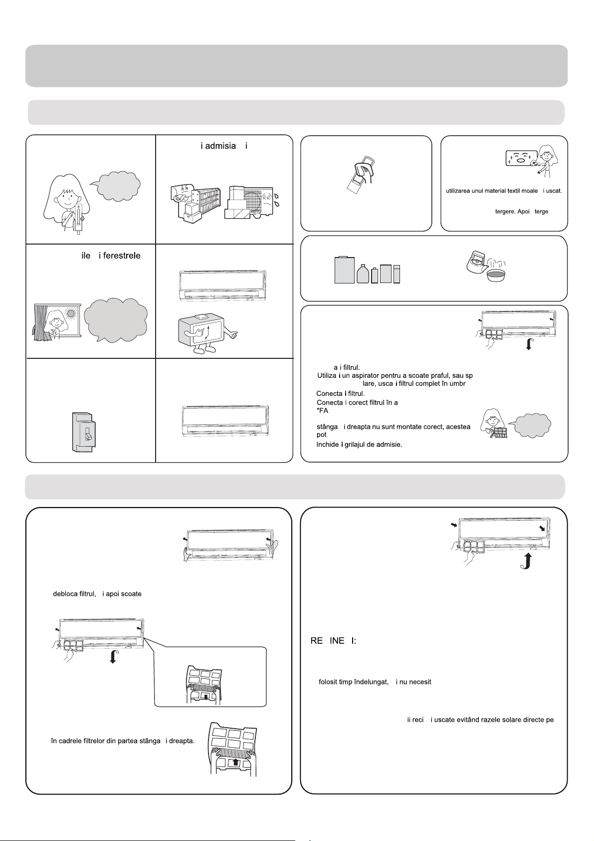
Întreţinere
Pentru o utilizare uşoară a aerului condiţionat
Setarea adecvată a
temperaturii camerei
Temperatura
adecvată
Închideţi uş
ş
în timpul funcţionării
În timpul operaţiei de răcire
preveniţi pătrunderea razelor
solare directe cu o perdea
sau stor.
Dacă aparatul nu este folosit
pentru o perioadă lungă de
timp, opriţi alimentarea.
ÎNCHIS
Nu blocaţ
ş
evacuarea de aer
Utilizaţi temporizatorul eficient
Utilizaţi gurile de aer eficient
Telecomandă Corp interior
Stergeţi aparatul de aer condiţionat prin
Pentru pete dificile, utilizaţi un detergent
Nu utilizaţi apă. Stergeţi telecomanda cu un
material textil uscat. Nu utilizaţi detergent de
ferestre sau material textil chimic.
neutru diluat cu apă. Înmuiaţi materialul textil
în apă înainte de ş
complet detergentul.
Pentru curăţare nu utilizaţi următoarele produse
Benzina, benzenul, diluantul sau
dezinfectant pot avaria stratul de lac al
Apa caldă peste 40°C(104° F) poate
cauza decolorare sau deformare.
Curăţarea filtrului de aer
1 Deschideţ
2 Scoateţi filtrul.
3 Cură
4
5
i fanta de evacuare prin ridicarea acesteia.
Apăsaţi uşor pe lamela centrală a filtrului până când se
deblochează de opritor, şi scoateţi filtrul descendent
ţ
ţ
ţ
apă. După spă
ţ
ţ
Ă" să fie orientată spre faţă. Asiguraţi-vă că filtrul
Ţ
este fixat complet în spatele opritorului. Dacă filtrele
cauza defecte.
ţ
ţ
şşa fel incât indicaţia
ălaţi filtrul cu
ă.
ş
O dată la două
săptămâni
ş
ţi
Înlocuirea filtrului de purificare a aerului
1. Deschideţi grilajul de admisie
Susţineţi grilajul de admisie prin
utilizarea unui dispozitiv mic numit
suport-grilaj care este localizat în partea
dreaptă a unităţii interioare.
2.Detaşaţi filtrul de aer standard
Mişcaţi uşor ascendent butonul pentru a
ş
3.Cuplaţi filtrul de purificare a aerului
Plasaţi produsele cu filtre de purificare a aerului
ţi-l.
Decuplaţi vechiul filtru de purificare a aerului
ş
4.Ataşaţi filtrul de aer standard
(Montaj necesar)
ATENTIE:
Partea de culoare albă a filtrului fotocatalitic de purificare a aerului este orientată
spre afară, iar partea de culoare neagră este orientată spre unitate. Partea de
culoare verde a mediul de ucidere a bacteriilor din interiorul filtrului de purificare a
aerului este orientată spre afară, iar partea albă este orientată spre interior.
5.Închideţ
i grilajul de admisie
Închideţi grilajul cu încredere
Ţ Ţ
• Filtrul fotocatalitic de purificare a aerului va fi solarizat într-un timp fix. Într-o
familie normală, acesta va fi solarizat la fiecare 6 luni.
• Mediul de ucidere a bateriilor din interiorul filtrului de purificare a aerului va fi
trebuie să eliminaţi praful frecvent prin utilizarea unui aspirator sau fluturarea
acestora uş
• Vă rugăm să menţineţi mediul de ucidere a bacteriilor din interiorul filtrului de
purificare a aerului în condiţ
timp lung în momentul opririi acestuia, sau abilitatea produsului de sterilizare
va fi redusă.
or, dacă nu, performanţa va fi afectată.
ş
ă înlocuire. Dar atunci când le utilizaţi,
ş
8
Page 11
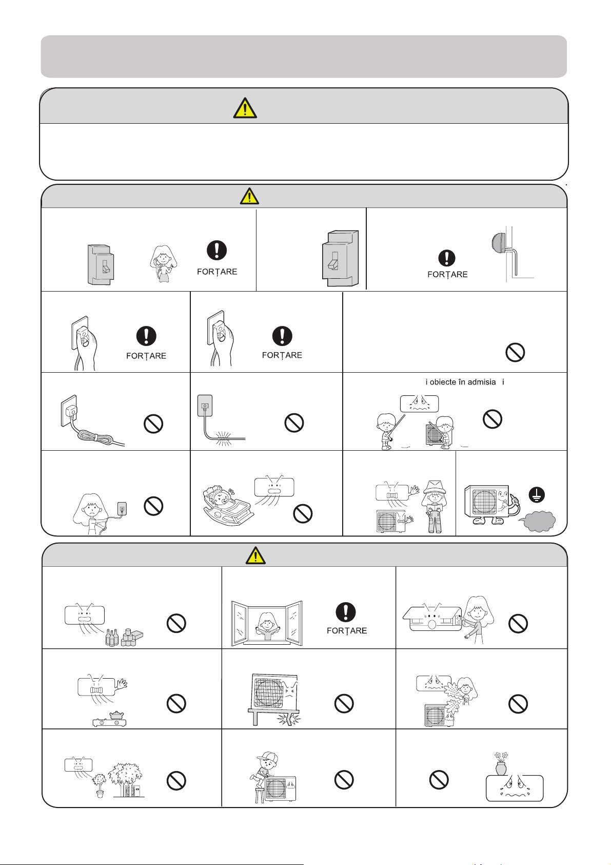
Precauţii
ţ
AVERTISMENT
Vă rugăm să sunaţi magazinul de vânzări/service pentru montaj.
Nu încercaţi să instalaţi aparatul de aer condiţionat de unul singur deoarece lucrările
neadecvat pot cauza şoc electric, incendiu, scăpări de apă.
AVERTISMENT
În momentul unor anormalitaţi cum este găsirea
unei componente arse, opriţi imediat aparatul şi
contactaţi magazinul de vânzări.
Utilizaţi o sursă
de putere
alternativă cu un
circuit electric.
Verificaţi instalarea în
siguranţă a drenajului.
ÎNCHIS
Conectaţi complet cablul de
alimentare la priză.
Nu utilizaţi cablul de
alimentare strâns.
STRICTĂ
STRICTĂ
Utilizaţi tensiunea adecvată
Asiguraţi-vă să nu deterioraţi cablul
de alimentare.
INTERZICERE
Nu porniţi sau opriţi funcţionarea
prin deconectarea cablului de
alimentare
Nu utilizaţi aparatul pentru păstrarea mâncării,
lucrărilor de artă, echipamentelor precise,
reproducere sau cultivare.
INTERZICERE
Nu directionaţi fluxul de aer direct spre
oameni, în special copiilor sau bătrânilor.
1 .Nu utilizaţi cablu de alimentare prelungit sau conectat la mijloc.
2.Nu montaţi aparatul în locul unde există posibilitatea scăpărilor de
gaze inflamabile pe lângă aparat.
3. Nu permiteţi expunerea aparatului la vapori sau aburi de ulei.
STRICTĂ
INTERZICERE
INTERZICERE
Nu introduceţ
evacuarea de aer
Nu încercaţi să reparaţi sau
să reconstruiţi aparatul de
unul singur.
AVERTISMENT
Inspiraţi aer proaspăt ocazional în special
când aparatele pe gaz funcţionează în acelaşi
moment.
STRICTĂ
INTERZICERE
INTERZICERE
Conectarea împământării
Nu atingeţi comutatorul cu mâinile
ude
ş
împământare
INTERZICERE
Nu montaţi aparatul lângă un şemineu sau
alte aparate de căldură.
Nu plasaţi animale sau plante în
calea fluxului de aer
INTERZICERE
INTERZICERE
Verificaţi buna condiţie a stand-ului
de montaj
Nu plasaţi obiecte sau urcaţi pe
aparat
STRICTĂ
INTERZICERE
INTERZICERE
Nu turnaţi apă în aparat pentru
cură
are.
Nu plasaţi vaze de flori sau recipiente
de apă pe partea superioară a
INTERZICERE
INTERZICERE
INTERZICERE
9
Page 12
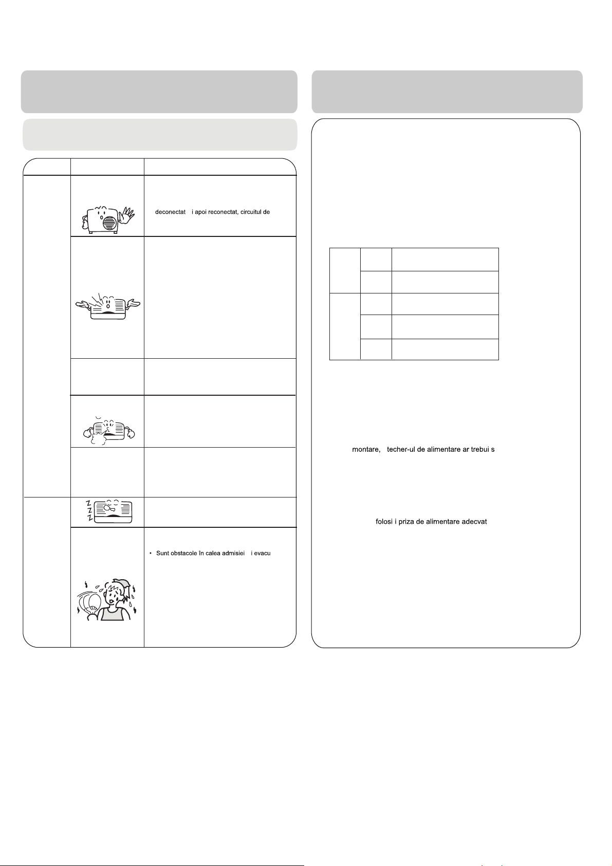
Depanare
•
Înainte de de apelarea la service, verificaţi mai întâi
următoarele.
Normal
Performanţă
Inspecţie
Verificări
multiple
Fenomen Cauza sau puncte de verificare
Sistemul nu
reporneşte imediat
Se aude zgomot
Se simt
mirosuri.
Ceată sau aburi ies din
aparat.
• În momentul când produsul este oprit, acesta nu
va reporni imediat decât după 3 minute pentru a
proteja sistemul.
• În momentul în care cablul electric este
protecţie va opera timp de 3 minute pentru a
proteja aparatul de aer condiţionat.
• În timpul funcţionării aparatului sau la oprire, este
posibil să auziţi un zgomot ca fiind un bolborosit. În
primele 2-3 minute după pornirea aparatului,
zgomotul este mai puternic (Acest zgomot este
creat de către refrigerent care curge prin sistem)
• În timpul funcţionării aparatului, un zgomot de
crăpare poate fi auzit. Acest zgomot este
generat de către dilatare sau contracţia
datorită schimbărilor de temperatură.
• Dacă auziţi un zgomot puternic de la fluxul de
aer în momentul funcţionării aparatului, este
posibil ca filtrul de aer să fie prea murdar.
• Acest lucru este datorat faptului că
sistemul pune în circulaţie mirosurile din
cameră cum ar fi mirosul de mobilier,
vopsea, ţigări.
• În timpul funcţionării modului RĂCIRE sau
DEUMIDIFICARE, unitatea interioară ar
putea sufla ceată. Acest lucru este datorat
răcirii rapide a aerului din interior
ş
În modul
DEUMIDIFICARE,
viteza ventilatorului nu
poate fi schimbată.
Răcire slabă
În modul DEUMIDIFICARE, când temperatura
camerei scade sub setarea temperaturii de
+2 °C,produsul va funcţiona intermitent la o viteză
SCĂZUTĂ indiferent de setarea
VENTILATORULUI.
• Este cablul de alimentare introdus?
• A survenit o pană de curent?
• Siguranţa este arsă?
• Este filtrul de aer murdar? În mod normal, acesta ar
trebui fi curăţat la fiecare 15 zile.
• Este temperatura setată corect?
• Există uşi sau ferestre încă deschise?
• Sunt raze solare directe care pătrund prin
fereastră în timpul operaţiei de răcire?(Utilizaţi
perdea)
• Sunt prea multe surse de caldură sau prea multe
persoane în timpul operaţiei de răcire?
ării?
ş
Precauţii
• Nu blocaţi sau acoperiţi fanta de ventilaţie a aparatului de aer
condiţionat. Nu puneţi degetele sau alte lucruri în
admisie/evacuare şi în fanta aflată în mişcare.
• Nu permiteţi copiilor să se joace cu aparatul de aer condiţionat. În
niciun caz nu
exterioară.
Specificaţii
• Circuitul refrigerentului este ermetic.
Aparatul este adaptabil în următoarele situaţii
1 .Gamă de temperatură ambientală aplicabilă:
Răcire
Incalzire
2. Dacă cablul de alimentare este deteriorat, acesta trebuie înlocuit de către
producător
similar.
3. Daca siguranţa din unitatea interioară de pe placa PC este arsă, vă
rugăm să o schimbaţi cu tipul T 3.15A/ 250V. Dacă siguranţa unităţii
exterioare este arsă, schimbaţi-o utilizând T25A/250V
4. Metoda de cablare ar trebui să fie conformă cu standardul local de cablare.
5. După
6. Bateria reziduală trebuie să fie depozitată în siguranţă.
7. Produsul nu este intenţionat utilizării de către copii tineri sau persoane
infirme fără supraveghere
8. Copii tineri ar trebui supravegheaţţi pentru a se asigura ca aceştia nu se
joacă cu produsul.
9. Vă rugăm să
cablul de alimentare.
10. Priza de alimentare şi cablul conectat trebuie să aibă atestare locală.
11.Pentru a proteja produsele, vă rugăm să închideţi mai întâi A/C, şi apoi
după 30 de secunde mai târziu să întrerupeţi alimentarea.
trebuie permis copiilor să stea pe unitatea
Interior
Exterior
Interior
Exterior
Exterior
(INVERTOR)
Maxim:D.B/W.B
Minim:D.B/W.B
Maxim:D.B/W.B
Minim: D.B
Maxim:D.B
Minim: D.B
Maxim:D.B/W.B
Minim:D.B/W.B
Maxim:D.B/W.B
Minim:D.B
32°C/23°C
21°C/15°C
46°C/26°C
18°C
27°C
15°C
24°C/18°C
-7°C/-8°C
24°C/18°C
-15°C
sau de către agentul de service sau o persoana calificată
ş
ă fie ajuns cu uşurinţă.
ă, care vine în contact cu
10
Page 13
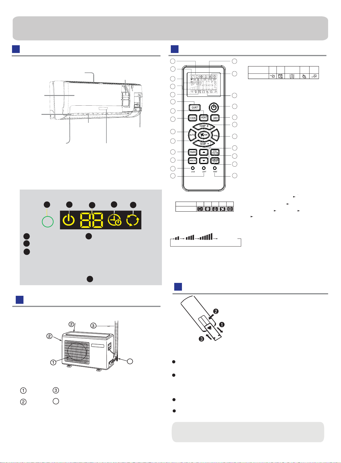
Parts and Functions
Indoor Unit
Inlet
Inlet grille
Outlet
Vertical blade
(adjust left and
ight air fl
Horizontal flap
(adjust up and down air flow
Don't adjust it manually)
r
Please be subject to the actual produce purchased the
above picture is just from your reference
Display board
1
1
Signal receiver hole
2
ON/OFF display
3
Ambient temp.display
When receiving the remote
control signal, display the set
temperature and in the rest
time the room temperature is
displayed and this room
temperature is only for reference.
2
4
Note to the power failure resume:
press the sleep button ten times in five seconds
and enter function after hearing four sounds.And
press the sleep button ten times within five
seconds and leave this function after hearing
two sounds.
5
Air Purifying Filter
(inside)
Emergency
ow)
Switch
Display board
3
4
5
TIMER ON\OFF display
TIMER ON-OFF display
SLEEP display
COOL\HEAT\Dry\AUTO display
Remote controller
1
2
3
4
5
9
10
11
12
13
14
15
16
17
1. Mode display
Operation mode
Remote controller
AUTO
COOL DRY
2. Signal sending display
3. SWING display
4. FAN SPEED display
LO MED HI
5. LOCK display
6. TIMER OFF display
TIMER ON display
7. TEMP display
Healthy function is not available for some units.
HEAT
FAN
Display
circulated
AUTO
6
7
Additional functions display
8.
Operation mode
Remote controller
9. QUIET button
10. HEAT button
8
11. COOL button
12. AUTO button
18
13. FAN SPEED button
14. TIMER button
19
15. HEALTH button
20
16. LOCK button
Used to lock buttons and LCD display
21
17. LIGHT button
Control the lightening and extinguishing
22
of the indoor LED display board.
18. POWER ON/OFF button
23
19. DRY button
24
20. TEMP button
21. SWING button
25
22. HOUR button
23. EXTRA FUNCTION button
Function: Sleeping---- Healthy
airflow position1--- Healthy airflow
position 2 --- Power --- Air sending
--- A-B yard
24.CANCEL/CONFIRM button
Function: Setting and cancel to the
timer and other additional functions.
25. RESET button
When the remote controller appears
abnormal, use a sharp pointed
article to press this button to reset
the remote.
Loading of the battery
QUIET
SLEEP
Supplemented
electrical
heating
HEALTH
TURBO
Outdoor Unit
4
OUTLET
INLET
Please be subject to the actual produce purchased the
above picture is just from your reference
CONNECTING PIPING AND ELECTRICAL WIRING
DRAIN HOSE
4
Remove the battery cover;
1
Load the batteries as illustrated.
2
2 R-03 batteries, resetting key
(cylinder);
Be sure that the loading
3
is in line with th
Load the battery,then put on the cover again.
4
Note:
The distance between the signal transmission head and the receiver hole should be within 7m without any obstacle as well.
When electronic-started type fluorescent lamp or change-over
type fluorescent lamp or
room, the recei
ver is apt to be disturbed in receiving
so the distance to the indoor unit should be shorter.
Full display or unclear display during operation indicates the
ries have been used up.
batte
If the remote controller can't run normally during operation, please
remove the batteries and
Hint:
Remove the batteries in case won't be in use for a long period. If
there is any display after taking-out, just press reset key.
wireless telephone is installed in the
Please change batteries.
reload several minutes later.
e" + "/"-";
the signals,
11
Page 14
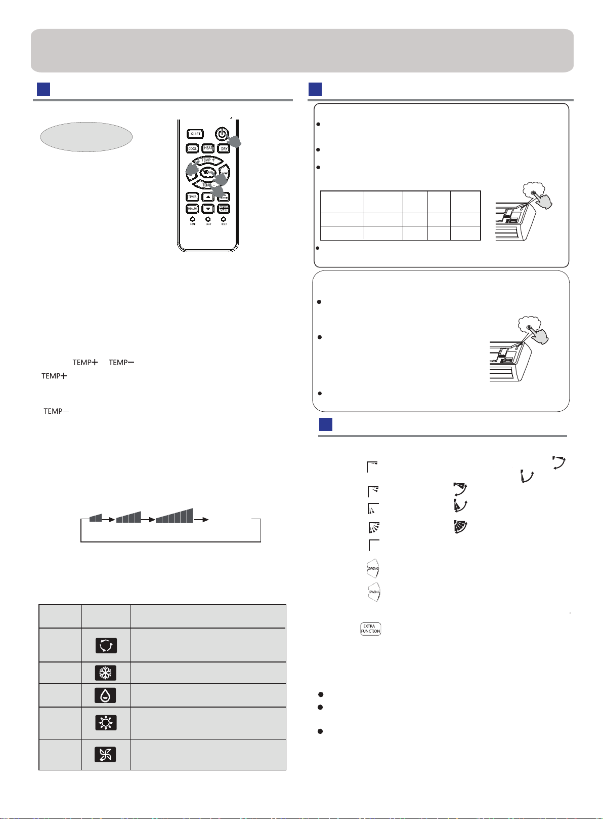
Operation
Base Operation
Remote controller
2
1. Unit start
Press ON/OFF on the remote controller, unit starts.
2. Select operation mode
COOL button:Cooling mode
HEAT button: Heating mode
DRY button: Dehumidify mode
3.Select temp.setting
Press
/
Every time the button is pressed, temp.setting
increase 1
rapidly
Every time the button is pressed, temp.setting
decrease 1
decrease rapidly
Select a desired temperature.
button
o
C,if kept depressed, it will increase
o
C,if kept depressed, it will
4.Fan speed selection
Press FAN button. For each press, fan speed
changes as
Remote controller:
Air conditioner is running under displayed fan speed.
When FAN is set to AUTO, the air conditioner
automatically adjusts the fan speed according to room
temperature.
follows:
LOW
MED HI
1
3
2
Display
circulated
AUTO
Emergency operation and test operation
Emergency Operation:
Use this operation only when the remote controller is defective
or lost, and with function of emergency running, air conditoner
can run automatically for a while.
When the emergency operation switch is pressed, the " Pi "
sound is heard once, which means the start of this operation.
When power switch is turning on for the first time and
emergency operation starts, the unit will run automatically in
the following modes:
Room
temperature
Above 23oC
Below 23
Designated
temperature
26
o
C 23oC
o
C
Timer
mode
No
No
Fan
speed
AUTO
AUTO
Operation
mode
COOL
HEAT
Pi
It is impossible to change the settings of temp. and fan speed,It
is also not possible to operate in timer or dry mode.
Test operation:
Test ope ration switch is the same as emergency switch.
Use this switch in the test operation when the room
temperature is below 16
normal operation.
Continue to press the test operation
switch for more than 5 seconds . After
you hear the "Pi" sound twice,
your finger from the switch: the cooling
operation starts with the air flow speed "Hi".
Under this operation mode,the fan motor of indoor
unit will run in high speed.
o
C, do not use it in the
release
Pi Pi
Air Flow Direction Adjustment
1.Vertical flap
Pos.1
Pos.2
Pos.3
Pos.4
(Autoswing)
Pos.5
2.Press button. changes as follows:
Press button again ,
Remote controller
COOL/DRY/AUTO(Initialstate):
HEAT(Initial state):
(no)
Pos.4
vertical flap will stop over
12
Operation
Mode
AUTO
COOL
DRY
HEAT
FAN
Remote
Controller
Note
Under the mode of auto operation, air conditioner will
automatically select Cool or Heat operation according to
room temperature. When FAN is set to AUTO the air
conditioner automatically adjusts the fan speed according
to room temperature.
In DRY mode , when room temperature becomes lower
than temp.setting+2
speed regardless of FAN setting.
In HEAT mode, warm air will blow out after a short
period of the time due to cold-draft prevention function.
When FAN is set to AUTO, the air conditioner automatically
adjusts the fan speed according to room temperature.
In FAN operation mode , the unit will not operate in COOL or
HEAT mode but only in
FAN mode. And temp. setting is disabled. In FAN mode,
sleep operation is not available.
o
C, unit will run intermittently at LOW
FAN mode, AUTO is not available in
present position,
3.Press
the swing function will be cancelled
button to choose the Pos.2 and Pos.3.
4.Left and right air flow adjustment(manual)
Move the vertical blade by a knob on airconditioner
to adjust left and right direction referring to Fig.
When adjusting the flap by hand,turn off the unit.
When humidity is high,condensate water might occur
adjusted to left or at air outlet if all vertical louvers are right.
It is advisable not to keep horizontal flap at downward
position for a long time in COOLor DRY
mode ,
otherwise, condensate water might occur.
Note:
When restart after remote turning off, the remote controller
controller will automatically memorize the previous set swing position.
Page 15
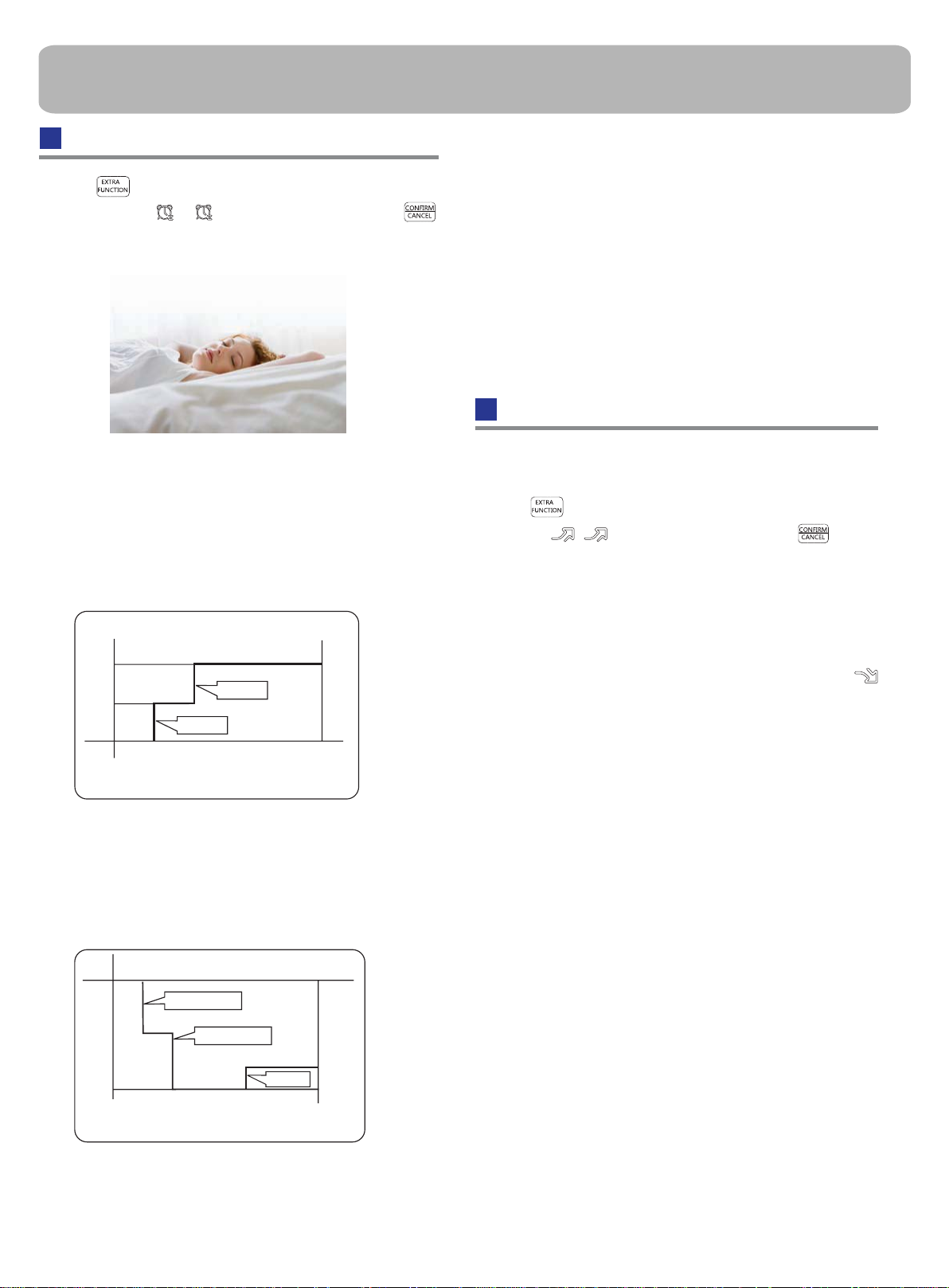
Operation
Sleep Operation
Press button to enter additional options, when
cycle display to , will flash. And then press
enter to sleep function.
Operation Mode
1. In COOL,DRY mode
1 hours after SLEEP mode starts,temp.will become
higher than temp.setting.After another 1 hours,temp.rises
O
C
by 1 futher.The unit will run for further
Temp. is higher than temp.setting so that room temperature
won’t be too low for your sleep.
6 hours then stops
O
C
1
4. In FAN mode
It has no SLEEP function.
5.Set the wind speed change when sleeping
If the wind speed is high or middle before setting for the
sleep, set for lowing the wind speed after sleeping.
If it is low wind, no change.
Note
When TIMER function is set, the sleeping function can’t be
if user resets
p
set up .After the sleeping function is set u
,
TIMER function, the sleeping function will be cancelled; the
machine will be in the state of
timing-on.
POWER/QUIET Operation
(1)
POWER Operation
When you need rapid heating or cooling, you can use this function.
Press button to enter additional options, when cycle
display to , will flash,and then press ,enter to
power function. When cancel the function, please enter
additional options again and to cancel power function.
SLEEP operation starts SLEEP operation stops
Approx.6hrs
Rises 1
Rises 1OC
O
C
Unit stop
1 hr
1 hr
Temp.setting
In COOL, DRY mode
In HEAT mode
2.
1 hours after SLEEP mode starts,temp will become 2
lower than temp.setting.After another 1 hours,temp
decrease by 2
by 1 futher.The unit will run for further 3 hours then
rises
O
C futher.After more another 3 hours,temp.
O
C
stops.Temp.is lower than temp. setting so that room
temperature won’t be
Temp.setting
1 hr
SLEEP
operation starts
too high for your sleep.
Decreases 2OC
1 hr
Decreases 2
3 hrs
Unit stop
O
C
3 hrs
Rises 1OC
SLEEP
operation stops
In HEAT mode
(2)
QUIET Operation
You can use this function when silence is needed for rest or reading.
Press QUIET button, the remote controller will show ,
and then achieve to the quiet function. Press again this
QUIET button , the quiet function will be cancelled.
Note ˖
During POWER operation, in rapid HEAT or COOL mode ,
O
C
the room will show inhomogeneous temperature distribution.
Long period QUIET operation will cause effect of not too
cool or not too warm.
In AUTO mode
3.
The unit operaters in corresponding sleep mode
adapted to the automatically selected operation
mode.
13
Page 16
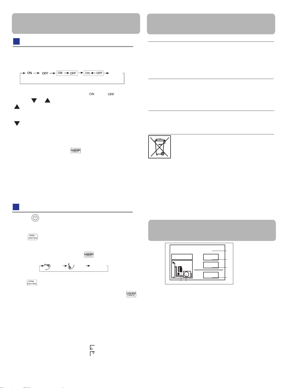
Operation
EUROPEAN REGULATIONS
CONFORMITY FOR THE MODELS
Timer On/Off On-Off Operation
1.After unit starts, select your desired operation mode.
2.Press TIMER button to change TIMER mode. Every
time the button is pressed, display changes as follows:
Remote controller:
0.5h
TIMER ON TIMER OFF TIMER ON-OFF
0.5h 0.5h
0.5h
TIMER OFF-ON
BLANK
Then select your desired TIMER mode (TIMER ON or
TIMER OFF or TIMER ON-OFF). " "or " "will flash.
3.Press / button to set time.
Press the button for each time, setting time in the first
12 hours increased by 0.5 hour every time, after 12
hours,increased by 1 hour every time.
Press the button for each time, settiing time in the first
12 hours decreased by 0.5 hour every time, after 12
hours,decreased by 1 hour every time.
It can be adjusted within 24 hours.
4.Confirm timer setting
After adjust the time,press button and confirm the
time ON or OFF button will not flash any more.
5.Cancel timer setting
Press the timer button by times until the time display
eliminated.
Hints:
After replacing batteries or a power failure happens, time
setting should be reset.
According to the Time setting sequence of TIMER ON or
TIMER OFF, either Start-Stop or Stop-Start can be achieved.
Healthy airflow Operation
1.Press to starting
Setting the comfort work conditions.
2.The setting of healthy airflow function
Press button to enter additional options,Press this
button continuously, the louvers location will cycle between
in the following three locations, to choose the swing location
what you needed,and then press button to confirm.
Healthy
airflow
upwarder
3.The cancel of the healthy airflow function
Press button to enter additional options,Press this
button continuously, the louvers location will cycle between
in the following three locations again,and then press
button to cancel.
Notice: Do not direct the flap by hand. Otherwise, the
grille will run incorrectly. If the grille is not run correctly, stop
for a minute and then start, adjusting by remote
controller.
Note:
1.After setting the healthy airflow function, the position
grill is fixed.
2.In heating, it is better to select the
3.In cooling, it is better to select the
4.In cooling and dry, using the air conditioner for a long
time under the high air humidity, condensate water may
occur at the grille .
14
Healthy
airflow
downwarder
Present
position
mode.
mode.
CE
All the products are in conformity with the following
European provision:
- Low Voltage Directive 73/23/EEC
- Low Voltage Directive 2006/95/EC
-Electomagnetic CompatibilitY 89/336/EEC
-Electomagnetic CompatibilitY 2004/108/EC
ROHS
The products are fulfilled with the requirements in the
directive 2002/95/EEC of the European parliament and of
council on the Restriction of the use of Certain Hazardous
Substances in Electrical and Electronic Equipment (EU
RoHS Directive)
WEEE
In accordance with the directive 2002/96/CE of the European
parliament, herewith we inform the consumer about the dis-
posal requirements of the electrical and electronic products.
DISPOSAL REQUIREMENTS:
Your air conditioning product is marked with this
symbol.This means that electrical and electronic
products shall not be mixed with unsorted
household waste. Do not try to dismantle the
system yourself : the dismantling of the air
conditioning system,treatment of the refrigerant, of oil and of
other part must be done by a qualified installer in
accordance
with relevant local and national legislation. Air conditioners
must be treated at a specialized treatment facility for reuse,
recycling and recovery. By ensuring this product is disposed
of correctly, you will help to prevent potential negative consequences for the environment and humen health. Please
contact the installer or local authority for more information.
Battery must be removed from the remote controller and disposed of separately in accordance with relevant local and
nationl legislation.
IMPORTANT INFORMATION REGARDING THE REFRIGERANT USED
Contains fluorinated greenhouse gases
covered by the Kyoto Protocol
R410A
2
FE
This product contains fluorinated greenhouse gases covered by
the Kyoto Protocol. Do not vent into the atmosphere.
Refrigerant type:R410A
GWP* value:1975
GWP=global warming potential
Please fill in with indelible ink,
WKHIDFWRU\UHIULJHUDQWFKDUJHRIWKHSURGXFW
WKHDGGLWLRQDOUHIULJHUDQWDPRXQWFKDUJHGLQWKHILHOG and
WKHWRWDOUHIULJHUDQWFKDUJH
on the refrigerant charge label supplied with the product.
The filled out label must be adhered in the proximity of the product
charging port (e.g. onto the inside of the stop value cover).
A contains fluorinated greenhouse gases covered by the Kyoto
Protocol
B factory refrigerant charge of the product: see unit name plate
C additional refrigerant amount charged in the field
D total refrigerant charge
E outdoor unit
F refrigerant cylinder and manifold for charging
1=
2=
1
1+2=
kg
kg
kg
A
B
C
D
Page 17
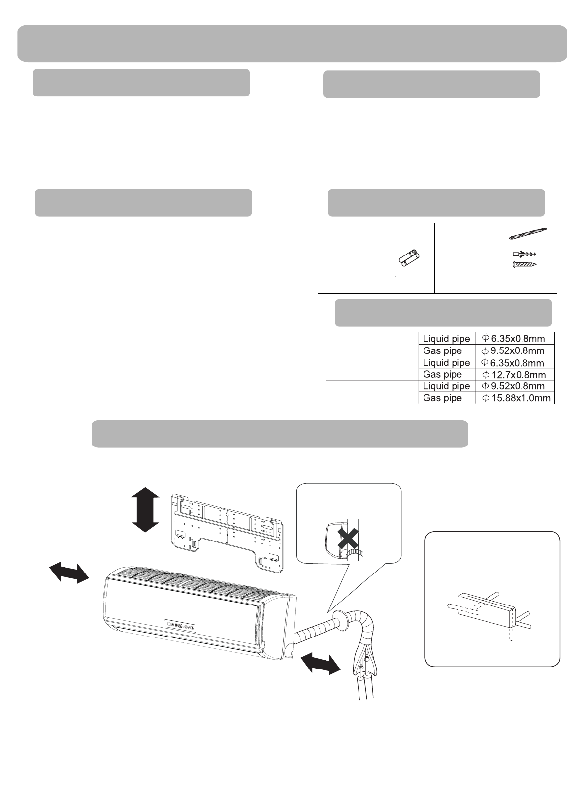
Indoor Unit Installaion
Necessary Tools for Installation
Torque wrench
Driverƽ
Nipperƽ
Hacksawƽ
Hole core drillƽ
Spanner(17,19 and 26mm)ƽ
Gas leakage detector orƽ
soap-and-water solution
ƽ
(17mm,22mm,26mm)
Pipe cutterƽ
Flaring toolƽ
Knifeƽ
Measuring tapeƽ
Reamerƽ
Selection of Installation Place
ƽ
Place, robust not causing vibration, where the body can be
supported suf¿ciently.
Place, not affected by heat or steam generated in the vicinity,
ƽ
where inlet and outlet of the
Place, possible to drain easily, where piping can be conne-
ƽ
cted with the outdoor unit.
Place,wherecoldaircanbespreadin a roomentirely.
ƽ
ƽ
Place, nearby a power receptacle, with enough space around.
ƽ
Place where the distance of more than lm from televisions,
radios, wireless apparatuses
left.
In the case of ¿xing the remote controller on a wall, place
ƽ
where the indoor unit can
scent
lamps
in the room are lightened.
unit are not disturbed.
a
nd Àuorescent lamps can be
receive signals when the Àuore-
Power Source
ƽ
Before inserting power
fail.
ƽ
The power
Install an exclusive branch circuit of the power.
ƽ
Areceptacleshallbesetupin a distancewherethepowercable
ƽ
be
can
supply is the same as the
reached.
into receptacle, check the voltage without
corresponding nameplate.
Donotextendthecablebycuttingit.
Accessory Parts
Remote controller (1)
R-03 dry battery (2)
Mounting plate (1)
Drain hose (1)
Plastic cap (4)
Ø4X25 Screw
Air purifying filter(Optional) (1)
(4)
Selection of Pipe
FOR 07K 09K 12K
FOR 18K
FOR 24K
Drawing for the installation of indoor units
ThemodelsadoptHFCfreerefrigerantR410A
more than 15cm
more than
10cm
The distance between
Please be subject to the actual product purchased,the above picture is just for your reference.
theindoorunitandthe
Attention must be paid to
the rising up of drain hose
more than 10cm
Àoor should be more
than 2m.
Arrangement of piping
directions
Rear left
Left
Below
Rear
right
Right
15
Page 18
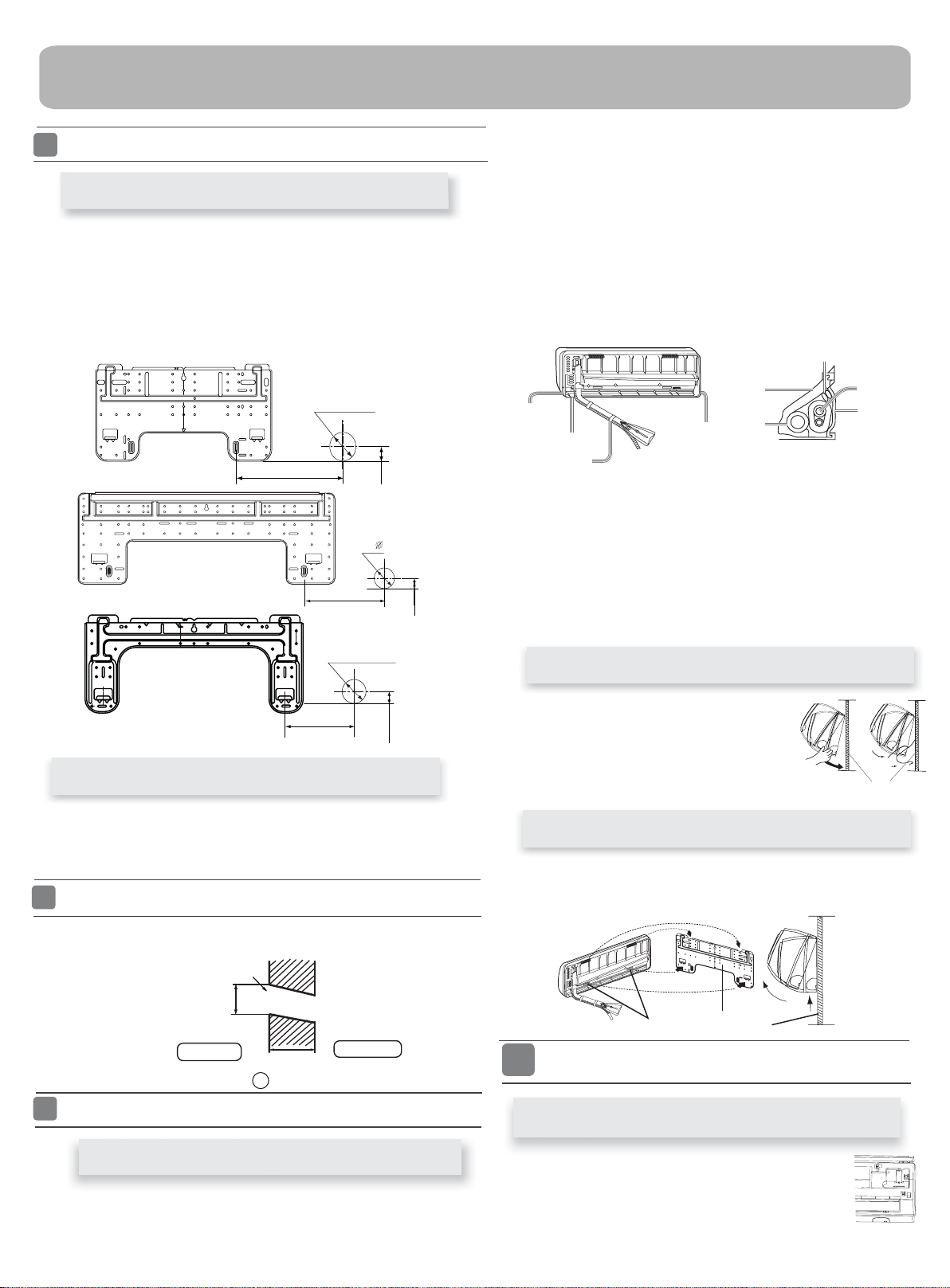
Indoor Unit Installation
1
FittingoftheMountingPlateand
Positioning of the wall Hole
When the mounting plate is ¿rst ¿xed
1.Carryout,basedontheneighboringpillarsorlintels, a
the plate
for
one steel nail.
with
2. Make sure once more the proper level of the plate, by
with a
plate with
3. Find the wall hole location A using a measuring tape
to be ¿xed against the wall, then temporarily fasten the plate
weight from the central top of the plate, then fasten securely the
attachment steel nail.
the
Ø
70mm
B=
A=145mm
B= 70mm
A=150mm
Ø
70mm
B=
proper leveling
hanging a thread
30mm
35mm
[Left·Left-rear piping ]
ƽ
In case of left side piping, cut away, with a nipper, the lid for left
piping.
ƽ
In case of left-rear piping, bend the pipes according to the piping
direction to
heat
1. Insert the drain hose into the dent of heat insulation materials of
indoor
2. Insert the indoor/outdoor electric cable from backside of indoor
unit,
3. Coat the Àaringsealfacewithrefrigerantoilandconnect pipes.
Cover the connection part with heat insulation materials closely,
and
Lid for right
piping
Lid for under piping pipe
Fix with adhesive tape
ƽ
Indoor/outdoorelectriccableanddrainhosemustbeboundwith
efrigerant
the mark of hole for left-rear piping which is marked on
insulation materials.
unit.
outonthefrontside,thenconnect them.
lit
and pul
make sure
¿xing with adhesive tape
Lid for left piping
piping by protecting tape.
Heat insulation
material
Drain hose
Indoor/outdoor electric cable
Piping
Pipe supporting
plate
[Otherdirectionpiping ]
Cut away, with a nipper, the lid for piping according to the piping
ƽ
direction
hole. When bending, be
ƽ
Connect beforehand the indoor/outdoor electric cable,
pull out the
specially.
then bend the pipe according to theposition of wall
and
careful not to crash
connected to the heat insulation of connecting part
pipes.
and then
Fixing the indoor unit body
A=145mm
30mm
When themountingplateis¿xedside barandlintel
Fix to side bar and lintel a mounting bar, Which is separately sold, and
ƽ
then
fasten the plate to the ¿xed mounting bar.
Refer to the previous article, “ When the mounting plate is
ƽ
for the
position of wall hole.
2
Making a Hole on the Wall and Fitting the Piping Hole Cover
Make a hole of 70 mm in diameter, slightly descending to outside the wall
ƽ
Install piping hole cover and seal it off with putty after installation
ƽ
Wall hole
Ø70mm
Indoor side
(Section of wall hole)
3
Installation of the Indoor Unit
Thickness of wall
Piping hole pipe
G
Outdoor side
¿rst ¿xed “,
Drawingofpipe
[Rearpiping ]
Drawpipesandthedrainhose,thenfastenthemwiththeadhesivetape
ƽ
Hangsurelytheunitbodyontotheupper
ƽ
notches of the
side to side to verify its
from
In order to ¿xthebodyontothemounting
ƽ
plate,hold up
underside and
mounting plate. Move the body
secure ¿xing.
thebodyaslantfromthe
then put it down
perpendicularly.
mounting plate
Unloading of indoor unit body
When you unload the indoor unit,please use your hand to arise
ƽ
the body to leave agraffe,then lift the bottom of the body outward
slightly and lift the unit aslant until it leaves the mounting plate.
agraffe
4
Connecting the indoor/outdoor Electric Cable
mounting plate
Removing the wiring cover
R
emove terminal cover at right bottom corner of
ƽ
indoor unit, then take
its screws.
offwiringcoverby removing
16
Page 19
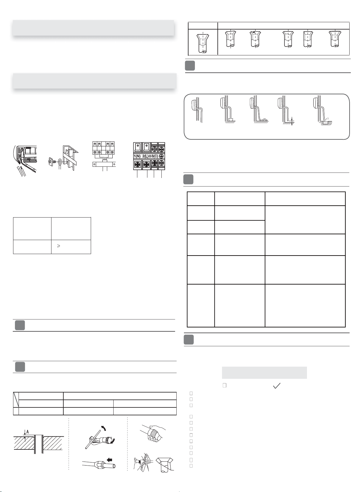
When connecting the cable after installing the indoor unit
Correct Incorrect
1. Insert from outside the room cable into left side of the wall
hole,inwhichthepipehasalreadyexisted.
2.Pulloutthecableonthefrontside,andconnectthecable
making a loop.
When connecting the cable before installing the indoor unit
Insertthecablefromtheback
ƽ
ƽ
Loosen the screws and insert
tighten the screws.
Pull the cable slightly to
ƽ
tightened.
After the cable connection,
ƽ
wiring cover.
side of the unit, then pull it out
the cable ends fully into
make sure the cables have
never fail to fasten the connected cable with the
been properly inserted and
on the front side.
terminal block, then
Indoor unit
To Outdoor unit
Note:
When connecting the cable, con¿rm the terminal number of indoor and
outdoor units carefully. If wiring is not correct, proper operation can not
becarriedoutandwillcausedefect.
BXEU 090/BXEU 091
Model
Connecting wiring
1.Ifthesupplycordisdamaged,itmustbereplacedbythemanufacturerorits
service agent or a similar quali¿ed person. The type of connecting wire is
H05RN-F
2.IfthefuseonPCboardisbrokenpleasechangeitwiththe
T.3.15A/250VAC (Indoor).
3.Thewiringmethodshouldbeinlinewiththelocalwiringstandard.
4. After installation, the power plug should be easily reached.
5. A breaker should be incorporated into ¿xedwiring.Thebreakershouldbe
all-pole
switchandthedistancebetweenitstwocontactsshouldbenotless
than 3mm.
5
Power Source Installation
ƽ
Thepowersourcemustbeexclusivelyusedforair
ƽ
In the case of installing an air conditioner in a moist place,
rth leakage breaker.
an ea
ƽ
For installation in other places, use a circuit breaker as far
6
Cutting and Flaring Work of Piping
Pipecuttingiscarriedoutwith a pipecutterandbursmust beremoved.
ƽ
After inserting the Àare nut, Àaring work is carried out.
ƽ
FlaretoolforR410A ConventionalÀare tool
Clutch-type clutch-type(Rigid-type) Wing-nut type (Imperial-type)
A 0~0.5mm 1.0~1.5mm 1.5~2.0mm
Flare tooling die
BXEU 120/BXEU 121
BXEU 180/BXEU 181
BXEU 240/BXEU 241
4G0.75mm
or H07RN-F.
2
1.Cut pipe
3.Insert the Àare nut
type of
conditioner.
please install
as possible.
2.Remove burs
4.Flare pipe
Lean
Damage of Àare Partial Too outside
7
On Drainage
Pleaseinstallthedrainhosesoastobedownwardslopewithoutfail.
ƽ
Pleasedon’tdothedrainageasshownbelow.
ƽ
It becomes
high midway.
Pleasepourwaterinthedrainpan of theindoorunit,and
ƽ
drainage
In case that the attached drain hose is in a room, please
ƽ
insulation
8
C ode
in d ic ati on
E1
E2
E4
The end is immersedinwater.
is carried out surely to outdoor.
it without fail.
to
On Drainage
Tro uble des crip tion
Room temperature
sensor failure
H eat- exch an g e
sens or failure
In d o o r E EP RO M
err or
It waves.
C om mun ica tio n
E7
fa u lt betw een
in d o or a n d ou tdoo r
units
Crack
Less than
5cm
The gap with the
ground is too small.
Thereisthebad
smell from a ditch
con¿rm that
apply heat
Analy ze a n d diagnos e
Faulty connect o r c o n nection;
Faulty th erm ist o r;
Faulty P C B;
Faulty E EP RO M da t
a;
Faulty E EP RO M;
Faulty P CB ;
In d o o r u n it - o u tdoo r u n it
sig n al
transm iss ion e rro r d ue to wirin g
err or;
Faulty P C B;
O p e rat io n hal t d u e t o br eakin g
of w ir e insid e the fan m ot or;
E14
In d o o r fan m otor
m a lf u nction
O p e rat io n hal t d u e t o br eakin g
of th e f a n m oto r lead w ire s ;
D ete cti on e rro r d ue to f a ulty
in d o or u n it PC B;
9
Check for Installation and Test Run
Pleasekindlyexplaintoourcustomershowto
Ƶ
operate
through the instruction manual.
CheckItemsforTestRun
Put check mark
Gasleakfrompipeconnecting?
Heat insulation of pipe connecting?
Are the connecting wirings of indoor and outdoor ¿rmly
inserted to the terminal block?
Is the connecting wiring of indoor and outdoor ¿rmly ¿xed?
Is drainage securely carried out?
Is the earth line securely connected?
Istheindoorunitsecurely¿xed?
Is power source voltage abided by the code?
Is there any noise?
Isthelampnormallylighting?
Arecoolingandheating(wheninheatpump)performednormally?
Is the operation of room temperature regulator normal?
in boxes
17
Page 20
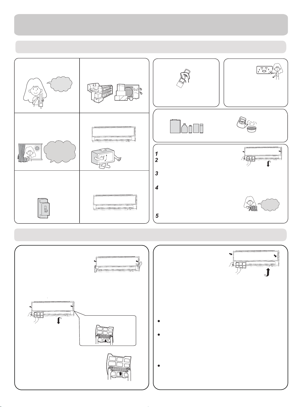
Maintenance
For Smart Use of The Air Conditioner
Setting of proper room
temperature
Proper
temperature
Close doors and windows
during operation
During cooling operation
prevent the penetration
of
direct sunlight with
curtain or blind
If the unit is not to be used
for a long time, turn off the
power supply main switch.
OFF
Do not block the air inlet
or outlet
Use the timer effectively
Use the louvers effectively
Remote Controller Indoor Body
wipe the air conditioner by using a
soft and dry cloth.For serious stains,
Do not usewater,wipe the controller
with a dry cloth.Do not use glass
cleaner or chemical cloth.
use a neutral detergent diluted with
water.Wring the water out of the
cloth before wiping,then wipe off the
detergent completely.
Do not use the following for cleaning
Gasoline,benzine, thinner or cleanser
damage the coating of the unit.
ay
m
Hot water over 40
cause
discoloring or deformation.
Air Filter cleaning
Open the inlet grille by pulling it upward.
Remove the filter.
Push up the filter's center tab slightly until it is
released
Clean the filter.
Use a vacuum cleaner to remove dust, or wash the filter with
water.After washing, dry the filter completely in the shade.
Attach the filter.
Attach the filter correctly so that the "FRONT" indication
is
completely
and left filters are not
may cause defects.
Close the inlet grille.
from the stopper, and remove the filter do
facing to the front.Make sure that the filter is
fixed behind the stopper.If the right
attached correctly, that
O
C(104OF) may
wnw
ard.
Once every
two weeks
Replacement of Air Purifying Filter
1.Open the lnlet Grille
Prop up the inlet grille by using a
small device named grille-support
which located in the right side of
the indoor unit.
2.Detach the standard air filter
Slide the knob slightly up
release the filter, then withdraw it.
3.Attach Air Purifying Filter
Put air purifying filter appliances into the
right and left filter frames.
ward to
Detach old Air Purifying Filter
4.Attach the standard air filter
(Necessar
y installation)
ATTENTION:
The white side of the photocatalyst air purifying filter
face outside,and the black side face the unit The green
side of the bacteria-killing medium air purifying filter face
outside,and the white side face the unit.
5.Close the Inlet Grille
Close the Grille surely
NOTE:
The photocatalyst air purifying filter will be solarized in fixed
time. In normal family,
The bacteria-killing medium air purifying filter will be used
for a long time,no need for replacement. But in the period
of using them ,you should remove the dust frequently by
using vacuum cleaner or flaping them lightly,otherwise ,
its performance will be affected.
Please keep the bacteria-killing medium air purifying filter in
the cool and dry conditions
when you stop using it,or its ability of sterilization will
reduced.
it will be solarized every 6 months.
avoid long time directly sunshine
be
18
Page 21
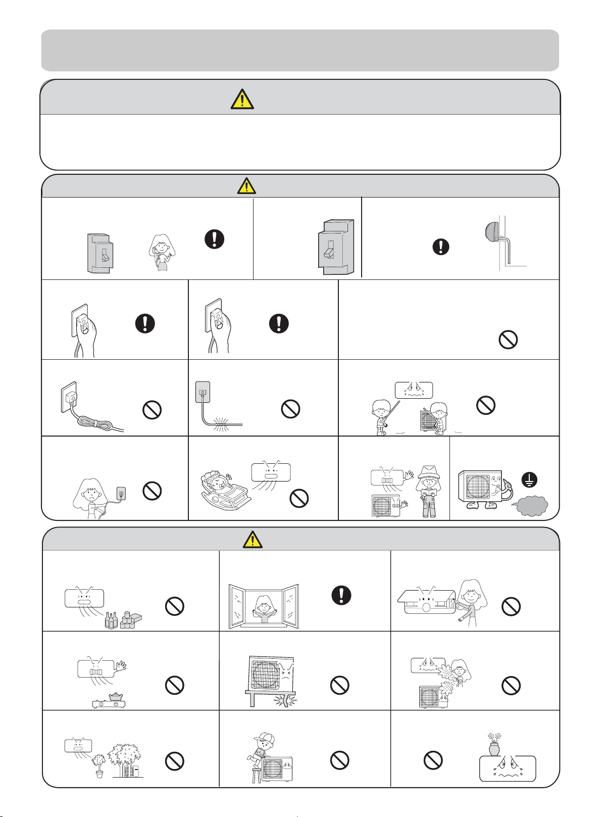
Cautions
WARNING
Please call Sales/Service Shop for the Installation.
Do not attempt to install the air conditioner by yourself because improper works
may cause electric shock, fire, water leakage.
WARNING
When abnormality such as burnt-small found,
immediately stop the operation button and
contact sales shop.
Use an exclusive
power source
with a circuit
breaker
Check proper
installation of the
drainage securely
OFF
Connect power supply cord
to the outlet completely
STRICT
ENFORCEMENT
Do not use power supply
cord in a bundle.
STRICT
ENFORCEMENT
Use the proper voltage
Take care not to damage
the power supply cord.
PROHIBITION
Do not start or stop the
operation by disconnecting
the power supply cord
and so on.
PROHIBITION
Do not use for the purpose of storage of
food, art work, precise equipment,
breeding, or cultivation.
Do not channel the air flow directly
at people, especially at infants or
the aged.
1.Do not use power supply cord extended
or connected in halfway
2.
Do not install in the place where there is any
possibility of inflammable gas leakage around the unit.
STRICT
ENFORCEMENT
PROHIBITION
PROHIBITION
3.Do not get the unit exposed
to vapor or oil steam.
Do not insert objects into the air
inlet or outlet.
Do not try to repair or
reconstruct by yourself.
CAUTION
Take fresh air occasionally especially
when gas appliance is running at the
same time.
STRICT
ENFORCEMENT
PROHIBITION
PROHIBITION
Connect the earth
cable.
earthing
Do not operate the switch with
wet hand.
PROHIBITION
Do not install the unit near a fireplace
or other heating apparatus.
PROHIBITION
Do not place animals or plants in
the direct path of the air flow
PROHIBITION
STRICT
ENFORCEMENT
Check good condition of the
installation stand
PROHIBITION
Do not place any objects on or
climb on the unit.
PROHIBITION
PROHIBITION
Do not pour water onto the unit
for cleaning
PROHIBITION
Do not place flower vase or water
containers on the top of the unit.
PROHIBITION
19
Page 22
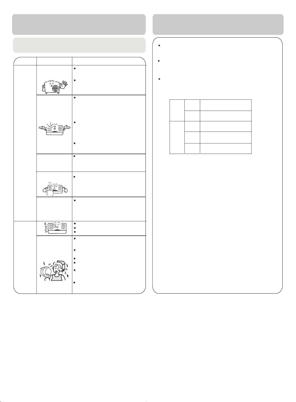
Trouble shooting
Cautions
Before asking for service, check the following
first.
Cause or check points
When unit is stopped, it won't restart
immediately until 3 minutes have
elapsed to protect the system.
When the electric plug is pulled out
and reinserted, the protection circuit
will work for 3 minutes to protect the
air conditioner.
During unit operation or at stop,
a swishing or gurgling noise may
be heard.At first 2-3 minutes after
unit start, this noise is more noticeable.
(This noise is generated by
refrigerant flowing in the system.)
During unit operation, a cracking
noise may be heard.This noise is
generated by the casing expanding
or shrinking because of
temperature changes.
Should there be a big noise from
air flow in unit operation, air
filter may be too dirty.
This is because the system
circulates smells from the interior
air such as the smell of furniture,
paint, cigarettes.
During COOL or DRY operation,
indoor unit may blow out mist.
This is due to the sudden cooling
of indoor air.
In DRY mode, when room temperature
becomes lower than temp.
setting+2
intermittently at LOW speed
regardless of FAN setting.
Is power plug inserted?
Is there a power failure?
Is fuse blownout?
Is the air filter dirty?
Normally it should be cleaned
every 15 days.
Are there any obstacles before
inlet and outlet?
Is temperature set correctly?
Are there some doors or
windows left open?
Is there any direct sunlight
through the window during the
cooling operation?(Use curtain)
Are there too much heat sources
or too many people in the room
during cooling operation?
o
C,unit will run
Normal
Performance
inspection
Multiple
check
Phenomenon
The system
does not restart
immediately.
Noise is heard
Smells are
generated.
Mist or steam are
blown out.
In dry mode,
speed can’t be
changed.
Poor cooling
fan
Do not obstruct or cover the ventilation
conditoner.Do not put fingers
inlet/outlet and
Do not allow children to play with the air
case should children be
swing louver.
or any other things into the
allowed to sit on the outdoor unit.
grille of the air
conditioner
Specifications
The refrigerating circuit is leak-proo f.
The machine is adaptive in following
1.Applicable ambient temperature range:
Indoor
Cooling
Outdoor
Indoor
Heating
Outdoor
Outdoor
(INVERTER)
2. If the power supply cord is damaged, it
manufacturer
3. If the fuse of indoor unit on PC board is
it with the type of
broken,change it with the type of
4. The wiring method should be in line with
5. After installation, the power plug should
6. The waste battery should be disposed
7. The appliance is not intended for use
persons
8.Young children should be supervised
the appliance.
with
9. Please employ the proper power plug,
cord.
The power plug and connecting cable
10.
attestation.
11.In order to protect the units,please turn
30 seconds
or its service agent or a similar
without supervision.
later, cutting off the power.
Maximum:D.B/W.B
Minimum:D.B/W.B
Maximum:D.B/W.B
Minimum:
Maximum:D.B
Minimum:
Maximum:D.B/W.B
Minimum:D.B/W.B
Maximum:D.B/W.B
Minimum:D.B
T. 3.15A/ 250V
D.B
D.B
must be replaced
broken,please
. If the fuse of
T.25A/250V
the local wiring
be easily reached.
properly.
by young children or
to ensure that th
which fit into the
must have
off the A/C first,
situation
32oC/23oC
o
21
C/15oC
o
46
C/26oC
o
18
C
o
C
27
o
15
C
o
C/18oC
24
o
-
C/-8oC
7
o
C/18oC
24
o
C
-15
qualified
outdoor
acquired the local
.In no
person.
change
unit is
standard.
ey
do not play
p
ower supply
and at least
by the
infirm
20
Page 23

Page 24

www.beko.com
 Loading...