

Beko Bekoblizz LC 12-355 Instructions For Installation And Operation Manual

1
EN - english
Instructions for installation and operation
Compressed air refrigeration chiller
BEKOBLIZZ
®
LC 12-355

2 BEKOBLIZZ® LC 12-355
Dear customer,
Thank you for deciding in favour of the BEKOBLIZZ
®
LC 12-355 compressed-air refrigeration chiller. Please read
these installation and operating instructions carefully before mounting and starting up the BEKOBLIZZ
®
LC 12-355 and
follow our directions. Perfect functioning of the BEKOBLIZZ
®
LC 12-355 and thus reliable compressed-air drying can
only be guaranteed when the provisions and notes stipulated here are strictly adhered to.

BEKOBLIZZ® LC 12-355 3
Contents
1
Name plate 5
2 Safety instructions 5
2.1 Safety pictograms in accordance with DIN 4844 6
2.2 Signal words in accordance with ANSI 8
2.3 Overview of the safety instructions 8
3 Proper use 11
4 Exclusion from a field of application 11
5 Operating instructions in accordance with the 97/23/EC Pressure Equipment Directive 12
6 Transport 13
7 Storage 13
8 Installation 14
8.1 Place of installation 14
8.2 Installation plan 15
8.3 Correction factors 16
8.4 Connection to the compressed-air system 17
8.5 Connection to the cooling-water network 17
8.6 Minimum cooling water requirements: 18
8.7 Electrical connections 19
8.8 Condensate drain 19
9 Start-up 20
9.1 Preliminary stages 20
9.2 Initial start-up 20
9.3 Shut down and restart 21
10 Technical data 22
10.1 Technical data BEKOBLIZZ LC 12-35 1/230/50-60 22
10.2 Technical data BEKOBLIZZ LC 55-355 1/230/50 23
10.3 Technical data BEKOBLIZZ LC 12-150 1/115/60 24
10.4 Technical data BEKOBLIZZ LC 55-355 1/230/60 25
11 Technical description 26
11.1 Control panel 26
11.2 Functional description 26
11.3 Flow chart (air-cooled) 27
11.4 Flow chart (water-cooled) 27
11.5 Refrigerating compressor 28
11.6 Condenser (air-cooled) 28
11.7 Condenser (water-cooled) 28
11.8 Cooling-water regulating valve 28
11.9 Filter dryer 28
11.10 Capillary tube 28
11.11 Air-to-refrigerant heat exchanger 28
11.12 Condensate separator 28
11.13 Hot-gas bypass valve 28
11.14 Refrigerant pressure switches LPS – HPS – PV 29
11.15 Safety temperature switch TS 29
11.16 DMC 15 electronics (control unit compressed-air chiller) – LC 12-35 30
11.16.1 Switching the chiller on 30
11.16.2 Switching the chiller off 30
11.16.3 Indication of a service warning/service alarm 30
11.16.4 Control of the condenser fan 31
11.16.5 Control of the drain solenoid valve (Not used) 31
11.16.6 Operating parameters – setup menu 31
11.17 DMC 18 electronics (control unit compressed-air chiller) – LC 55-355 32
11.17.1 Switching the chiller on 32
11.17.2 Switching the chiller off 32
11.17.3 Indication of the operating parameters 32
11.17.4 Indication of a service warning/service alarm 32
11.17.5 Operation of the potential-free failure/alarm contact 33
11.17.6 Operating parameters – setup menu 33

4 BEKOBLIZZ® LC 12-355
11.17.7 Selection of the Bekomat drain model 33
11.18 Electronically level-controlled BEKOMAT condensate drain 34
12 Maintenance, troubleshooting, spare parts and dismantling 35
12.1 Checks and maintenance 35
12.2 Troubleshooting 36
12.3 Recommended spare parts 39
12.4 Maintenance works at the refrigeration cycle 42
12.5 Dismantling the chiller 42
13 Appendices 43
13.1 Chiller dimensions 43
13.1.1 Chiller dimensions BEKOBLIZZ LC 12-35 43
13.1.2 Chiller dimensions BEKOBLIZZ LC 55 44
13.1.3 Chiller dimensions BEKOBLIZZ LC 90-115 45
13.1.4 Chiller dimensions BEKOBLIZZ LC 150-240 46
13.1.5 Chiller dimensions BEKOBLIZZ LC 355 47
13.2 Exploded diagrams 48
13.2.1 Components of the exploded diagrams 48
13.2.2 Exploded diagram BEKOBLIZZ LC 12-35 49
13.2.3 Exploded diagram BEKOBLIZZ LC 55 50
13.2.4 Exploded diagram BEKOBLIZZ LC 90-115 51
13.2.5 Exploded diagram BEKOBLIZZ LC 150-240 52
13.2.6 Exploded diagram BEKOBLIZZ LC 355 53
13.3 Electric diagrams 54
13.3.1 Electric diagrams – list of components 54
13.3.2 Electric diagram BEKOBLIZZ LC 12-35 55
13.3.3 Electric diagram BEKOBLIZZ LC 55 56
13.3.4 Electric diagram BEKOBLIZZ LC 90-115 57
13.3.5 Electric diagram BEKOBLIZZ LC 150-240 58
13.3.6 Electric diagram BEKOBLIZZ LC 355 59
14 EC Declaration of Conformity 61
Pos: 1 /Beko Technische Dokumentation/Überschrif ten/1/Sicherheitshin weise @ 0\mod_11836376092 61_6.doc @ 5365
Name plate
BEKOBLIZZ® LC 12-355 5
1 Name plate
The name plate is on the back of the chiller and comprises all primary data of the device. Always refer to these when
contacting the manufacturer or the sales department.
All guarantee claims will expire in the event that the name plate is modified or removed.
The chiller model printed on the nameplate includes one or more suffixes that specify one or more features of chiller.
Explanation of 1st suffix for power supply requirements :
1st SUFFIX DESCRIPTION OF FEATURE
none 1/230/50
-P 1/115/60
-E 1/230/60
Explanation of 2nd suffix for cooling requirements :
2nd SUFFIX DESCRIPTION OF FEATURE
/ AC Air cooled
/ WC Fresh water cooled
Explanation of (eventual) 3rd suffix for special features :
3rd SUFFIX DESCRIPTION OF FEATURE
-TAC Anti corrosion treatment
-SP Special feature
-OF Chiller oil free
Examples : BEKOBLIZZ LC115-P /AC BB LC115 1/115/60, Air cooled
BEKOBLIZZ LC355 /WC BB LC355 1/230/50, Water cooled
BEKOBLIZZ LC240-E /AC -TAC BB LC240 1/230/60, Air cooled, Anti corrosion treatment
2 Safety instructions
Pos: 2 /Beko Technische Dokumentation/Globale Texte/A llgemeiner Hinweis B M @ 0\mod_1183615737313_6. doc @ 4004
Pos: 3 /Beko Technische Dokumentation/Sicherheit/Hin weis Anleitung BEKO @ 0\ mod_1184147787557_6. doc @ 5758
Please check whether or not these instructions correspond to the device type.
Please adhere to all advice given in these operating instructions. They include essential information
which must be observed during installation, operation and maintenance. Therefore, it must be ensured
that these operating instructions are read by the fitter and the responsible operator / certified skilled
personnel prior to installation, start-up and maintenance.
The operating instructions must be accessible at all times at the place of application of the BEKOBLIZZ
®
LC 12-355 compressed-air refrigeration chiller.
In addition to these operating instructions, local and national regulations need to be observed, where
required .
Ensure that operation of the BEKOBLIZZ
®
LC 12-355 compressed-air refrigeration chiller only takes
place within the permissible limit values indicated on the name plate. Any deviation from these limit
values involves a risk for persons and for the material, and may result in malfunction or a breakdown.
After installing the device correctly and in accordance with the instructions in this manual, the chiller is
ready to operate, further settings are not required. Operation is fully automatic and maintenance is
limited to several examinations and cleaning measures which are described in the following chapters.
This manual must be available at all times for future reference and is a constituent part of the chiller.
If you have any queries regarding these installation and operating instructions, please contact BEKO
TECHNOLOGIES GMBH.
Safety instructions
6 BEKOBLIZZ® LC 12-355
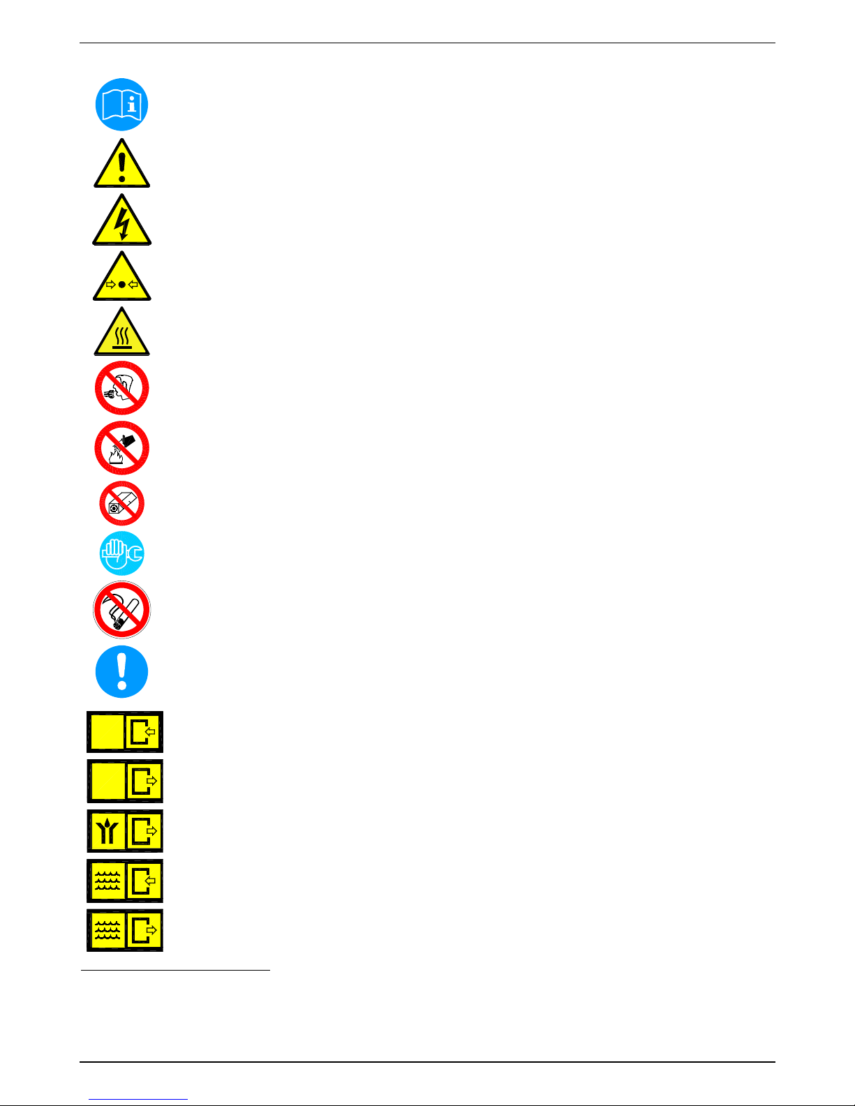
2.1 Safety pictograms in accordance with DIN 4844
Observe operating instructions
General danger symbol
Supply voltage
Danger: component or system under pressure
Hot surfaces
Non-breathable air
Do not use water to extinguish the fire
Do not operate with open cover (housing)
Maintenance works or controlling measures must only be carried out by qualified personnel
1
Do not smoke
Note
Pos: 4 /Beko Technische Dokumentation/Sicherheit/Gef ahr Druckluft @ 0\mod_118 4148143854_6.doc @ 577
6
ARIA
AIR
LUFT
AIR
Connection point compressed-air inlet
ARIA
AIR
LUFT
AIR
Connection point compressed-air outlet
Connection point condensate drain
Connection point cooling-water inlet (water-cooled)
Connection point cooling-water outlet (water-cooled)
1
Certified skilled personnel are persons who are authorised by the manufacturer, with experience and technical training, who are
well-grounded in the respective provisions and laws and capable of carrying out the required works and of identifying and avoiding
any risks during the machine transport, installation, operation and maintenance.
Qualified and authorised operators are persons who are instructed by the manufacturer regarding the handling of the refrigeration
system, with experience and technical training, and who are well-grounded in the respective provisions and laws.

Safety instructions
BEKOBLIZZ® LC 12-355 7
Works can be carried out by the operator of the plant, provided that they are skilled accordingly2.
NOTE: Text that contains important specifications to be considered – does not refer to safety precautions.
The device was carefully designed with particular attention paid to environmental protection:
CFC-free refrigerants
CFC-free insulation material
Energy-saving design
Limited acoustic emissions
Chiller and packaging comprise reusable materials
This symbol advises the user to observe the environmental aspects and comply with the recommendations
connected with this symbol.
2
Certified skilled personnel are persons who are authorised by the manufacturer, with experience and technical training, who are
well-grounded in the respective provisions and laws and capable of carrying out the required works and of identifying and avoiding
any risks during the machine transport, installation, operation and maintenance.
Qualified and authorised operators are persons who are instructed by the manufacturer regarding the handling of the refrigeration
system, with experience and technical training, and who are well-grounded in the respective provisions and laws.
Safety instructions
8 BEKOBLIZZ® LC 12-355
2.2 Signal words in accordance with ANSI
Danger!
Imminent hazard
Consequences of non-observance: serious injury or death
Warning!
Potential hazard
Consequences of non-observance: possible serious injury or death
Caution!
Imminent hazard
Consequences of non-observance: possible injury or property damage
Notice!
Potential hazard
Consequences of non-observance: possible injury or property damage
Important!
Additional advice, info, hints
Consequences of non-observance: disadvantages during operation and maintenance, no danger
2.3 Overview of the safety instructions
Certified skilled personnel
Installation works must exclusively be carried out by authorised and qualified skilled personnel. Prior to
undertaking any measures on the BEKOBLIZZ
®
LC 12-355 compressed-air refrigeration chiller, the
certified skilled personnel shall read up on the device by carefully studying the operating instructions.
The operator is responsible for the adherence to these provisions. The respective directives in force
apply to the qualification and expertise of the certified skilled personnel.
For safe operation, the device must only be installed and operated in accordance with the indications in
the operating instructions. In addition, the national and operational statutory provisions and safety
regulations, as well as the accident prevention regulations required for the respective case of
application, need to be observed during employment. This applies accordingly when accessories are
used.
Danger!
Compressed air!
Risk of serious injury or death through contact with quickly or suddenly escaping compressed
air or through bursting and/or unsecured plant components.
Compressed air is a highly dangerous energy source.
Never work on the chiller when the system is under pressure.
Never direct the compressed-air outlet or condensate drain hoses at persons.
The user is responsible for the proper installation of the chiller. Non-observance of the instructions in
the "Installation" chapter leads to the expiration of the guarantee. Improper installation may result in
dangerous situations for the personnel and/or the device.
Pos: 5 /Beko Technische Dokumentation/Sicherheit/Maßna hmen Druckluft BM @ 0\mod_11 84148284291_6.doc @ 5812
Pos: 6 /Beko Technische Dokumentation/Sicherheit/Gef ahr Netzspannung @ 0\ mod_1184148186948_6.doc @ 5794
Danger!
Supply voltage!
Contact with non-insulated parts carrying supply voltage involves the risk of an electric shock
resulting in injuries and death.
Only qualified and skilled personnel are authorised to run electrically-operated devices. Prior to
undertaking maintenance measures at the device, the following requirements must be met:
Make sure that the power supply is switched off and that the device is off and marked for maintenance
measures. Please also ensure that the power supply cannot be re-established during the works.
Pos: 7 /Beko Technische Dokumentation/Sicherheit/Maßna hmen Netzspannung B M 31/32/33 @ 0\mod_121689843 0699_6.doc @ 11319
Caution!
Refrigerant!
The compressed-air refrigeration chiller uses HFC-containing refrigerants as a coolant.
Please observe the corresponding paragraph entitled "Maintenance works at the refrigeration cycle".
Safety instructions
BEKOBLIZZ® LC 12-355 9
Warning!
Refrigerant leak!
A refrigerant leak involves the danger of serious injury and damage to the environment.
The BEKOBLIZZ
®
LC 12-355 compressed-air refrigeration chiller contains fluorinated greenhouse
gas/refrigerant.
Installation, repair and maintenance works at the refrigeration system must only be carried out by
certified skilled personnel (specialists). A certification in accordance with EC regulation 303/2008 must
be available.
The requirements of the EC 842/2006 directive must be met under all circumstances.
Please refer to the indications on the name plate as regards the type and amount of refrigerant.
Comply with the following protective measures and rules of conduct:
Storage: Keep the container tightly closed. Keep it in a cool and dry place. Protect it against heat
and direct sunlight. Keep it away from ignition sources.
Handling: Take measures against electrostatic charging. Ensure good ventilation/suction at the
workplace. Check fittings, connections and ducts for tightness. Do not inhale the gas. Avoid contact
with the eyes or the skin.
Prior to carrying out works on refrigerant-carrying parts, remove the refrigerant to such an extent
that safe working is possible.
Do not eat, drink or smoke during work. Keep out of the reach of children.
Breathing protection: ambient-air-independent respirator (at high concentrations).
Eye protection: sealing goggles.
Hand protection: protective gloves (e.g. made of leather).
Personal protection: protective clothing.
Skin protection: use protective cream.
In addition, the safety data sheet for the refrigerant needs to be observed!
Caution!
Hot surfaces!
During operation, several components can reach surface temperatures of more than +60°C.
There is the risk of burns.
All components concerned are installed inside of the closed housing. The housing must only be
opened by certified skilled personnel
3
.
Caution!
Improper use!
The device is intended for the separation of water in compressed air. The dried air cannot be used for
breathing-air purposes and is not suitable for the direct contact with food.
This chiller is not suitable for the treatment of contaminated air or of air containing solids.
3
Certified skilled personnel are persons who are authorised by the manufacturer, with experience and technical training, who are
well-grounded in the respective provisions and laws and capable of carrying out the required works and of identifying and avoiding
any risks during the machine transport, installation, operation and maintenance.
Qualified and authorised operators are persons who are instructed by the manufacturer regarding the handling of the refrigeration
system, with experience and technical training, and who are well-grounded in the respective provisions and laws.

Safety instructions
10 BEKOBLIZZ® LC 12-355
Note!
Contaminated intake air!
In the event that the intake air is strongly contaminated (ISO 8573.1 class 3.-3 or poorer quality), we
recommend the additional installation of a prefilter (e.g. CLEARPOINT F040), to avoid clogging of the
heat exchanger.
Caution!
Heating-up through fire!
In the event of a heating-up through fire, the containers and pipes of the refrigerant system can
burst.
In this case, please proceed as follows:
Switch off the refrigeration plant.
Switch off the mechanical ventilation of the machinery compartment.
Use ambient-air-independent respirators.
Containers and plants which are filled with refrigerant can burst violently in the event of fire.
The refrigerants themselves are incombustible, but they are degraded to very toxic products at high
temperatures.
Remove the container/plant from the fire zone, as there is the risk of bursting!
Cool down containers and bottles via a directed water jet from a safe position.
In the event of fire, please use an approved fire extinguisher. Water is not a suitable agent to
extinguish an electrical fire.
This must only be carried out by persons who are trained and informed about the hazards emanating
from the product.
Caution!
Unauthorised intervention!
Unauthorised interventions may endanger persons and plants and lead to malfunction.
Unauthorised interventions, modification and abuse of the pressure devices are prohibited.
The removal of sealings and leadings at safety devices is prohibited.
Operators of the devices must observe the local and national pressure equipment regulations in the
country of installation.
Pos: 8 /Beko Technische Dokumentation/Sicherheit/Si cherheitshinweise, weitere BM (nicht Ex) @ 0\ mod_1183616103770_6.doc @ 4009os: 9 /Beko Technisc he Dokumentation/Si cherheit/Zusatz Sic herheitshinweise B M33 @ 0\mod_123192688762 0_6.doc @ 12829s: 10 /Beko Techni sche Dokumentati on/Sicherheit/Vor sicht Fehlfunktion @ 0\ mod_1214378096290_6. doc @ 9359
Note!
Ambient conditions!
In the event that the chiller is not installed under suitable ambient conditions, the ability of the device to
condense refrigerant gas is impaired. This can result in a higher load of the refrigerating compressor,
and in a loss of efficiency and performance of the chiller.
This in turn leads to overheated condenser fan motors, to malfunction of electric components and to a
breakdown of the chiller. Failures of this type will affect warranty considerations.
Do not install the chiller in an environment in which chemicals with a corrosive effect, explosive gases,
toxic gases, evaporation heat, high ambient temperatures or extreme dust and dirt can be found.
Pos: 12 /Beko Technische Dokumentation/Überschri ften/1/Bestimmungsge mäße Verwendung @ 0\mod_118 3637706293_6.doc @ 5383

Proper use
BEKOBLIZZ® LC 12-355 11
3 Proper use
This chiller was designed, manufactured and tested to separate the moisture which normally exists in compressed air.
Any other use is considered improper.
The manufacturer shall not be liable for problems occurring as a consequence of improper use. The user alone is
responsible for any damage resulting from that.
Furthermore, the correct use includes the compliance with the installation instructions, in particular in respect of:
• The voltage and frequency of the main voltage supply.
• The pressure, temperature and flow rate of the inlet air.
• The pressure, temperature and cooling-water throughput (water-cooled).
• The ambient temperature.
When delivered, the chiller is tested and fully assembled. The customer only needs to connect the device to the system
in accordance with the instructions in the following chapters.
Pos: 15 /Beko Technische Dokumentation/Übeschrif ten/1/Ausschluss vom Anw endungsbereich @ 0\ mod_1236003439359_6.doc @ 13709
4 Exclusion from a field of application
Pos: 16 /Beko Technische Dokumentation/Bestimmungsge mäße Verwendung/BEKOMA T/Ausschluß Anwendun g BM 31/32/33 @ 0\mod_123600383 7511_6.doc @ 13736
Note!
Improper use!
The device is intended for the separation of water in compressed air. The dried air cannot be used for
breathing-air purposes and is not suitable for the direct contact with food.
This chiller is not suitable for the treatment of contaminated air or of air containing solids.

Operating instructions in accordance with the 97/23/EC Pressure Equipment Directive
12 BEKOBLIZZ® LC 12-355
5 Operating instructions in accordance with the 97/23/EC Pressure Equipment Directive
The BEKOBLIZZ® LC 12-355 compressed-air refrigeration chiller contains pressure equipment in the sense of the
97/23/EC Pressure Equipment Directive. Therefore, the entire plant needs to be registered with the supervisory
authority if required in accordance with the local regulations.
For the examination prior to the start-up and for periodic inspections, the national regulations need to be observed,
such as the industrial safety regulation in the Federal Republic of Germany. In countries outside the EU, the respective
regulations in force there need to be adhered to.
The proper use of pressure devices is the basic requirement for safe operation. As regards pressure devices, the
following points need to be observed:
The BEKOBLIZZ
®
LC 12-355 compressed-air refrigeration chiller must only be employed within the pressure and
temperature range limits indicated by the manufacturer on the name plate.
No welding must be carried out on the pressure parts.
The BEKOBLIZZ
®
LC 12-355 compressed-air refrigeration chiller must neither be installed in insufficiently
ventilated rooms nor near heat sources or inflammable substances.
To avoid fractures resulting from material fatigue, the refrigeration chiller should not be exposed to vibrations
during operation.
The maximum operating pressure indicated by the manufacturer on the name plate must not be exceeded. It is the
installer's responsibility to install the appropriate safety and control devices. Prior to the start-up of the
BEKOBLIZZ
®
LC 12-355 compressed-air refrigeration chiller, the connected pressure generator (compressor etc.)
must be set to the max. permissible operating pressure. The integrated safeguard needs to be checked by an
approved inspection agency.
The documents related to the BEKOBLIZZ
®
LC 12-355 compressed-air refrigeration chiller (manual, operating
instructions, manufacturer's declaration etc.) must be kept safe for future reference.
No objects whatsoever must be installed at or placed on the BEKOBLIZZ
®
LC 12-355 compressed-air refrigeration
chiller and the connecting lines.
Installation of the plant in frost-free places only.
Operation of the plant is only permissible with fully closed and intact housing and cover panels. Operation of the
plant with damaged housing/cover panels is prohibited.

Transport
BEKOBLIZZ® LC 12-355 13
6 Transport
Check the packaging for visible loss or damage. If no visible damage can be ascertained, place the unit in close
proximity to the place of installation and unpack the device.
During this procedure, the chiller must always remain in an upright position. The components may be damaged when
the unit is tilted or turned upside down.
Store the device in a dry environment and do not expose it to extreme weather conditions.
Handle with care. Strong shocks can cause irreparable damage.
7 Storage
S
C
C
0
0
0
1
Keep the device away from extreme weather conditions
even when packaged.
Keep the chiller in an upright position, also while it is
stored. Tilting the device or turning it upside down can
cause irreparable damage to some components.
When the chiller is not in use, it can be stored in its
packaging in a dust-free and protected place at a
temperature of up to max. 50°C and at a specific humidity
of max. 90%. If the storage period exceeds 12 months,
you should contact the manufacturer.
The packaging material is recyclable. Dispose of the material in accordance with the
directives and provisions in force in the country of destination

Installation
14 BEKOBLIZZ® LC 12-355
8 Installation
8.1 Place of installation
Note!
Ambient conditions!
In the event that the chiller is not installed under suitable ambient conditions, the ability of the device to
condense refrigerant gas is impaired. This can result in a higher load of the refrigerating compressor, and in
a loss of efficiency and performance of the chiller.
This in turn leads to overheated condenser fan motors, to malfunction of electric components and to a
breakdown of the chiller. Failures of this type will affect warranty considerations.
Do not install the chiller in an environment in which chemicals with a corrosive effect, explosive gases, toxic
gases, evaporation heat, high ambient temperatures or extreme dust and dirt can be found.
Minimum installation requirements:
• Choose an area which is clean and dry, free from dust and protected against atmospheric disturbances.
• The load-bearing zone must be even, horizontal and able to bear the weight of the chiller.
• Minimum ambient temperature +1°C.
• Maximum ambient temperature +50°C.
• Ensure a proper cooling air replacement.
• Allow a sufficient clearance on each side of the chiller for proper ventilation and to facilitate maintenance operations.
The chiller does not require attachment to the floor surface.
Do not obstruct the ventilation grille (not even partially).
Prevent any recirculation of the outgoing cooling air.
Protect the chiller against draughts.
Note!
Chillers models LC 12 – 55 can be wall-mounted. See fixing dimensions on dimensional drawings in the
appendices section.
The hanging mounting inevitably causes the obstruction of the ventilation grid positioned on the panel
facing the wall fixing. This obstruction, in any case, does not prejudge the efficiency of the ventilation
inside the chiller which is guaranteed by other grids on the other panels.
Installation
BEKOBLIZZ® LC 12-355 15
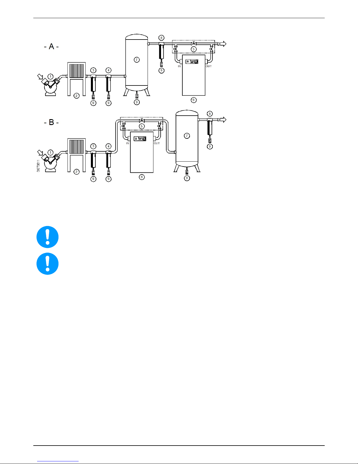
8.2 Installation plan
1 Air compressor
2 Aftercooler
3 Condensate separator
4 Prefilter
5 Bypass group
6 Chiller
7 Compressed-air tank
8 Final filter
9 Bekomat condensate drain
Installation type A straight upstream of the application is recommended.
Installation type B is NOT recommended because of the low compressed air temperature there will be condensation
outside of the pipes and vessel and the air will be rewarmed.
Do not obstruct the ventilation grille (not even partially).
Prevent any recirculation of the outgoing cooling air.
Protect the chiller against draughts.
Note!
Contaminated intake air!
In the event that the intake air is strongly contaminated (ISO 8573.1 class 3.-3 or poorer quality), we
recommend the additional installation of a prefilter (e.g. CLEARPOINT F040), to avoid clogging of the
heat exchanger.
Installation
16 BEKOBLIZZ® LC 12-355
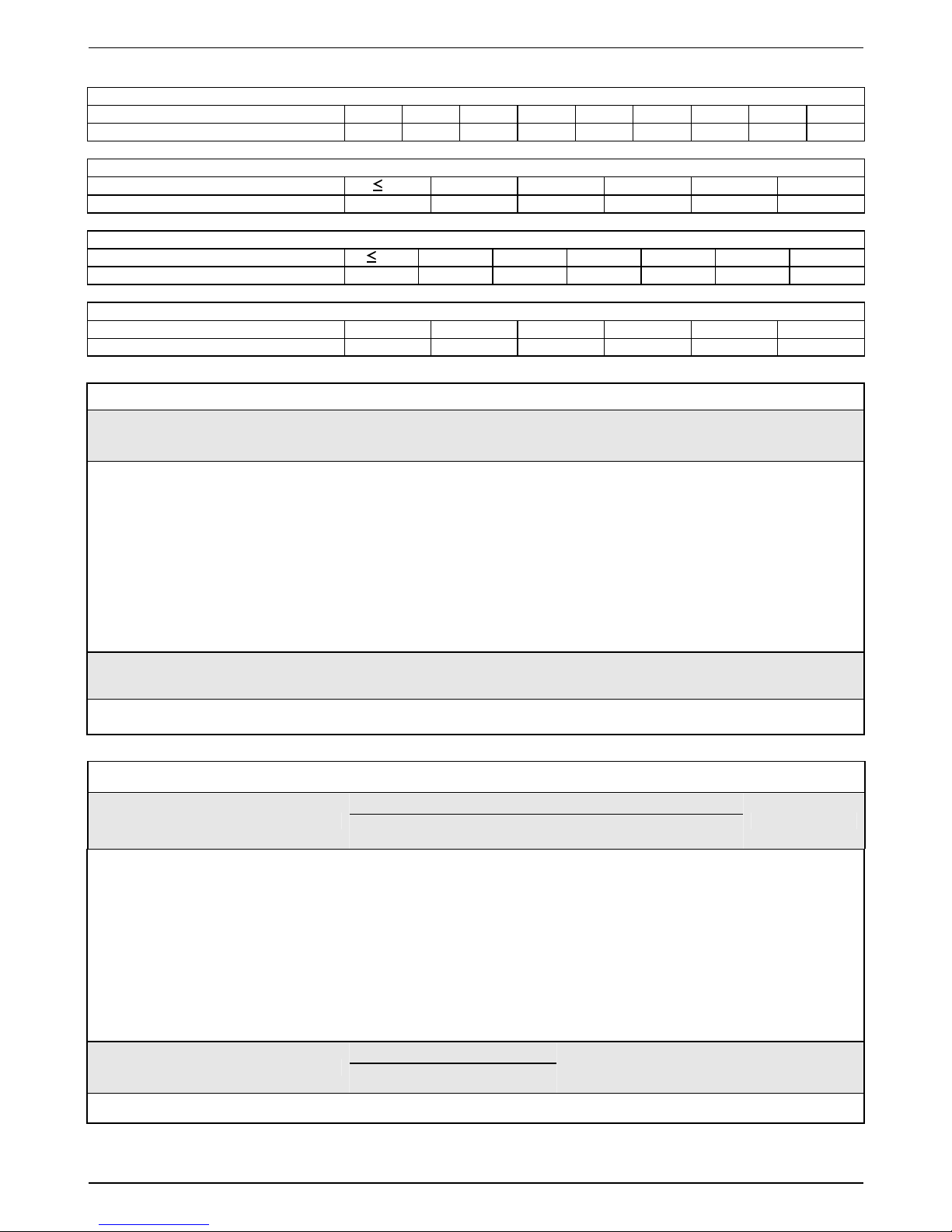
8.3 Correction factors
Correction factor for operating pressure changes:
Inlet air pressure bar(g) 4 5 6 7 8 10 12 14 15
Factor (F1) 0.77 0.86 0.93 1.00 1.05 1.14 1.21 1.27 1.30
Correction factor for ambient temperature changes (Air-Cooled):
Ambient temperature ºC 25 30 35 40 45 50
Factor (F2) 1.00 0.96 0.90 0.82 0.72 0.60
Correction factor for inlet air temperature changes:
Air temperature ºC 25 30 35 40 45 50 55
Factor (F3) 1.39 1.20 1.00 0.80 0.63 0.51 0.46
Correction factor for DewPoint changes:
DewPoint ºC 4 5 7 10 15 20
Factor (F4) 0.88 1.00 1.04 1.15 1.42 1.82
Calculation of the actual air throughput:
Actual air throughput = air throughput acc. to planning x factor (F1) x factor (F2) x factor (F3) x factor (F4)
Example:
The BEKOBLIZZ LC 240 has a planned nominal capacity of 240 m³/h. The highest achievable air mass
under the following operating conditions is:
Air inlet pressure = 8 bar(g)
Ambient temperature = 35°C
Air inlet temperature = 40°C
Pressure dew point = 5°C
Factor (F1) = 1.05
Factor (F2) = 0.90
Factor (F3) = 0.80
Factor (F4) = 1.00
Every function parameter corresponds to a numerical factor which, multiplied by the planned nominal capacity,
determines the following:
Actual air throughput = 240 x 1.05 x 0.90 x 0.80 x 1.00 = 181 m³/h
181 m³/h is the maximum flow rate of the chiller under the aforementioned operating conditions.
Selection of the best suitable model in accordance with the operating conditions:
Air throughput acc. to planning =
Requ. air throughput
Factor (F1) x Factor (F2) x Factor (F3) x Factor (F4)
Example:
The following operating parameters are known:
Required air mass = 100 m3/h
Air inlet pressure = 8 bar(g)
Ambient temperature = 35°C
Air inlet temperature = 40°C
Pressure dew point = 5°C
Factor (F1) = 1.05
Factor (F2) = 0.90
Factor (F3) = 0.80
Factor (F4) = 1.00
To find out the correct chiller version, the required air mass must be divided by the correction factors of the
parameters indicated above:
Air throughput acc. to planning =
100
= 132 m³/h
1.05 x 0.90 x 0.80 x 1.00
The suitable model for these requirements is BEKOBLIZZ LC 150 (with a spec. nominal capacity of 150 m³/h).
Installation
BEKOBLIZZ® LC 12-355 17
8.4 Connection to the compressed-air system
Danger!
Compressed air!
All works must only be carried out by qualified skilled personnel.
Never work on compressed-air systems which are under pressure.
The operator or the user must ensure that the chiller is never operated with a pressure exceeding the
maximum pressure value indicated on the name plate.
Exceeding the maximum operating pressure can be dangerous for the operator but also for the device.
The air temperature and the air flow at the inlet of the chiller must lie within the limit values indicated on the name
plate. The connecting lines must be free from dust, iron rust, shards and other contaminations and correspond to the
flow rate of the chiller. Should air with a very high temperature be treated, the installation of an aftercooler may be
necessary. For the implementation of maintenance works, the installation of a bypass system is recommended.
Note!
Pulsation and vibrations!
Pulsations and vibrations must be eliminated from the compressed air and IN/OUT piping to avoid
possible fatigue failure.
Do not use the chiller to treat air containing corrosive substances for copper and its alloys..
CAUTION!
During the piping of the chiller, the inlet and outlet connections need to be supported as is shown in the
illustration.
Non-observance will cause damage.
===== Ende der Stückliste =====
Note!
Contaminated intake air!
In the event that the intake air is strongly contaminated (ISO 8573.1 class 3.-3) or poorer quality, we
recommend the additional installation of a prefilter (e.g. CLEARPOINT F040), to avoid clogging of the
heat exchanger.
8.5 Connection to the cooling-water network
Danger!
Compressed air and unqualified personnel!
All works must only be carried out by qualified skilled personnel.
Never work on compressed-air systems which are under pressure.
The user must ensure that the chiller is never operated with a pressure exceeding the nominal values.
Possible overpressure can be dangerous for the operator but also for the device.
The temperature and the amount of cooling water need to correspond to the limit values indicated on the name plate.
The cross-section of the connecting lines, which should preferably be flexible, must be free from dust, iron rust, shards
and other contaminations. We recommend employing connecting lines (flexible hoses, vibration-inhibiting fittings etc.)
which protect the chiller against possible vibrations in the pipework.
Note!
Contaminated intake water!
In the event that the intake water is strongly contaminated we recommend the additional installation of a
prefilter (500 micron), to avoid clogging of the heat exchanger.
Installation
18 BEKOBLIZZ® LC 12-355
8.6 Minimum cooling water requirements:
Temperature
15 … 30°C (1) HCO
3
/ SO4 >1.0 mg/l or ppm
Pressure 3…10 bar(g) (2) NH
3
<2 mg/l or ppm
Delivery pressure > 3 bar (2) (3) Cl
-
50 mg/l or ppm
Total hardness 6.0…15 dH° Cl
2
0.5 mg/l or ppm
PH 7.5…9.0 H2S
<0.05 mg/l or ppm
Conductivity 10…500 μS/cm CO
2
<5 mg/l or ppm
Residual solids <30 mg/l or ppm NO
3
<100 mg/l or ppm
Saturation mark SI -0.2 < 0 < 0.2 Fe <0.2 mg/l or ppm
HCO
3
70…300 mg/l or ppm Al <0.2 mg/l or ppm
SO
4
2-
<70 mg/l or ppm
Mn <0.1 mg/l or ppm
Note: (1) – Other temperatures upon request – check the data on the name plate.
(2) – Other pressures upon request – check the data on the name plate.
(3) – Pressure difference at the water connection of the chiller at maximum water flow.
Other delivery pressures upon request.
CAUTION!
During the piping of the chiller, the inlet and outlet connections need to be supported as is shown in the
illustration.
Non-observance will cause damage.
Installation
BEKOBLIZZ® LC 12-355 19
8.7 Electrical connections
Danger!
Supply voltage!
The connection to the electric mains should only be carried out by qualified skilled personnel and must
correspond to the legal provisions in force in your region.
Prior to connecting the device, please check the name plate to avoid exceeding the indicated values. The voltage
tolerance is +/- 10%.
BEKOBLIZZ LC 12-240 chillers are supplied with a VDE 16A standard power cord and safety plug (two-pole and earth
connection). BEKOBLIZZ LC 355 device have a junction box on the back plate.
Make sure that suitable fuses or circuit breakers in accordance with the indications on the name plate are available.
A residual-current device (RCD) with In=0.03A is suggested. The cross-section of the power supply cable must
correspond to the power consumption of the chiller. In this respect, the ambient temperature, the cable laying
conditions, the length of the cables and the requirements of the local electricity supplier need to be considered.
Danger!
Supply voltage and missing earth connection!
Important: ensure that the plant is connected to earth.
Do not use plug adapters at the power plug.
Possible replacement of the power plug must only be carried out by a qualified electrician.
8.8 Condensate drain
Danger!
Compressed air and condensate under pressure!
The condensate is discharged at system pressure.
The drain pipe needs to be secured.
Never direct the condensate drain pipe at persons.
The chiller is delivered with an already integrated electronically level-controlled BEKOMAT condensate drain. Connect
the condensate drain with a collection system or container by properly screwing it on.
Do not connect the drain with pressurised plants.
Do not discharge the condensate into the environment.
The condensate accumulating in the chiller contains oil particles which were released into the air by the
compressor.
Dispose of the condensate in accordance with the local provisions.
It is advisable to install a water-oil separator, to which the total amount of condensate from the
compressors, chillers, tanks, filters etc. is supplied.
We recommend ÖWAMAT oil-water separators for dispersed compressor condensate and BEKOSPLIT
emulsion-splitting plants for emulsified condensate.
Start-up
20 BEKOBLIZZ® LC 12-355
9 Start-up
9.1 Preliminary stages
Note!
Exceeding of the operating parameters!
Ensure that the operating parameters comply with the nominal values indicated on the name plate of the
chiller (voltage, frequency, air pressure, air temperature, ambient temperature etc.).
Prior to delivery, this chiller was thoroughly tested, packed and checked. Please verify the soundness of the chiller
during the initial start-up and check the perfect functioning during the first operating hours.
The initial start-up must be carried out by qualified personnel.
During the installation and operation of this device, all national regulations regarding electronics and
any other federal and state ordinances, as well as local provisions, need to be adhered to.
The operator and the user must ensure that the chiller is not operated without panels.
9.2 Initial start-up
Note!
The chiller must not be started up more than six times an hour. Wait at least five minutes prior to
every restart.
The user is responsible for the compliance with these provisions. Irreparable damage can be caused by
starting up the device too often.
The method below should be applied during the first start-up, after longer downtimes or subsequent to
maintenance works.
The start-up must be carried out by certified skilled personnel.
Processing sequence (see Section 11.1 "Control panel")
Ensure that all steps of the "Installation" chapter have been carried out.
Ensure that the connection to the compressed-air system is in accordance with the provisions and that the lines are
fixed and supported properly.
Ensure that the condensate drain pipe is fixed in accordance with the provisions and that it is connected with a
collection system or a container.
Ensure that the bypass system (if installed) is open and that the chiller is disconnected from the compressed-air
system.
Ensure that the manual valve of the condensate drainage cycle is open.
Ensure that the cooling-water flow and the cooling-water temperature are in accordance with the provisions (water-
cooled).
Remove any packaging material and other items which may block the space around the chiller.
Establish the mains connection (plug into socket).
• Start the chiller by switching on the main switch on the control panel (pos. 1).
• Make sure that the electronic control unit is switched on.
• Ensure that the power consumption complies with the values on the name plate.
• Ensure that the fan runs properly – wait for the first interventions (air-cooled).
• Wait until the dew point remains stable.
• Slowly open the air inlet valve.
• Slowly open the air outlet valve.
• Slowly close the central bypass valve of the system (if installed).
• Check the pipes for air leakage.
• Ensure the proper functioning of the condensate drain cycle (wait for the first condensate discharges).
 Loading...