

Page 1
B13 B7S B7SLED WASHING MACHINE SERVICE HAND BOOK
SERVICE HANDBOOK NO:1
B13 B7S-B7SLED CONTROL SYSTEM
WASHING MACHINE
SERVICE HANDBOOK
Page 2

B13 B7S B7SLED WASHING MACHINE SERVICE HAND BOOK
1. DOOR
2. Contents
1. DOOR………………………………………….………..………………………………..1
1. DOOR ...................................................................................................................................................... 2
2. CONTENTS ............................................................................................................................................... 2
3. SECURITY WARNINGS .............................................................................................................................. 5
3.1. GENERAL SECURITY ................................................................................................................................... 5
3.1.1. Electrical safety ............................................................................................................................... 5
3.1.2. Product safety ................................................................................................................................. 5
3.2. INTENDED USE ......................................................................................................................................... 6
3.3. CHILD SAFETY ........................................................................................................................................... 6
3.4. COMPLIANCE TO ROHS DIRECTIVE ............................................................................................................... 6
3.5. PACKAGING INFORMATION .......................................................................................................................... 7
3.6. DISPOSAL OF WASTE PRODUCT ..................................................................................................................... 7
3.7. POINTS TO CONSIDER DURING SERVICE .......................................................................................................... 7
4. PRODUCT INSTALLATION / INSTALLATION RULES / SETTINGS ................................................................. 9
4.1. CORRECT PLACE FOR INSTALLATION .............................................................................................................. 9
4.2. REMOVING THE PACKAGE SUPPORT ............................................................................................................ 10
4.3. REMOVING THE TRANSPORT SAFETY BOLTS .................................................................................................. 10
4.4. CONNECTION TO THE SUPPLY WATER.......................................................................................................... 11
4.5. CONNECTION TO THE WATER DRAIN ............................................................................................................ 12
4.6. ADJUSTMENT OF LEGS .............................................................................................................................. 13
4.7. ELECTRICAL CONNECTION .......................................................................................................................... 14
4.8. TRANSPORTATION OF THE PRODUCT............................................................................................................ 14
5. USE OF PRODUCT AND BYPRODUCTS .................................................................................................... 16
5.1. PREPARATION......................................................................................................................................... 16
5.1.1. Sorting the Laundry ....................................................................................................................... 16
5.1.2. Preparation of the garments to be washed ................................................................................... 17
5.1.3. Things to do for energy saving ...................................................................................................... 18
5.1.4. Correct load capacity ..................................................................................................................... 18
5.1.5. Laundry loading ............................................................................................................................. 19
5.1.6. Use of detergent and softener....................................................................................................... 19
5.1.7. First Use ......................................................................................................................................... 22
5.2. CONTROL PANEL ..................................................................................................................................... 23
5.3. PREPARING THE MACHINE ........................................................................................................................ 24
5.4. PROGRAM SELECTION AND TIPS FOR CORRECT WASHING ................................................................................. 25
5.5. MAIN PROGRAMS ................................................................................................................................... 26
5.6. ADDITIONAL PROGRAMS ........................................................................................................................... 26
5.7. SPECIAL PROGRAMS ................................................................................................................................. 27
5.8. TEMPERATURE SELECTION ......................................................................................................................... 27
5.9. AUXILIARY FUNCTION SELECTION ................................................................................................................ 28
5.10. STARTING THE PROGRAM .......................................................................................................................... 30
5.11. CHILD LOCK ........................................................................................................................................... 30
5.12. PROGRESS OF THE PROGRAM .................................................................................................................... 31
5.13. LOCK OF THE LOADING DOOR ..................................................................................................................... 31
5.14. CHANGING THE SELECTIONS AFTER THE PROGRAM STARTED ............................................................................. 31
5.15. CANCELLATION OF PROGRAM .................................................................................................................... 32
5.16. PROGRAM END ....................................................................................................................................... 32
5.17. THERE IS A “STANDBY MODE” IN YOUR MACHINE .......................................................................................... 32
6. MAINTENANCE AND CLEANING ............................................................................................................. 33
2
Page 3

B13 B7S B7SLED WASHING MACHINE SERVICE HAND BOOK
6.1. CLEANING THE DETERGENT DISPENSER ......................................................................................................... 33
6.2. CLEANING THE LOADING DOOR AND THE DRUM ............................................................................................ 34
6.3. CLEANING THE BODY AND CONTROL PANEL ................................................................................................... 34
6.4. CLEANING THE WATER INLET FILTERS ........................................................................................................... 35
6.5. DRAINING THE REMAINING WATER AND CLEANING THE PUMP FILTER ................................................................. 35
7. . GENERAL OPERATING PRINCIPLE ......................................................................................................... 39
7.1. WATER INTAKE PROFİLE ........................................................................................................................... 39
7.2. HEATİNG PROFİLE ................................................................................................................................... 41
7.3. ANTİ-FOAMİNG PROFİLE ........................................................................................................................... 41
7.4. FOAM DETECTİNG AND EXTİNGUİSHİNG ALGORİTHM ..................................................................................... 42
7.5. PROGRAMME FLOWS ............................................................................................................................... 43
8. COMPONENT WORKING PRINCIPLES ..................................................................................................... 48
8.1. ELECTRONİC CONTROL AND VİSUAL CARD .................................................................................................... 48
8.2. SAFETY SWITCH (DOOR LOCK) ................................................................................................................... 49
8.3. MOTOR................................................................................................................................................. 49
8.4. HEATER ................................................................................................................................................. 50
8.5. VALVE ................................................................................................................................................... 50
8.6. DRAIN PUMP ......................................................................................................................................... 50
8.7. NTC ...................................................................................................................................................... 51
8.8. WATER LEVEL SENSOR ............................................................................................................................. 51
9. SERVICE FUNCTION TEST ....................................................................................................................... 53
10. B13 B7S B7SLED FAILURE FLOW DIAGRAM ............................................................................................ 57
11. LIST OF EQUIPMENT/APPARATUS TO BE USED IN COMPONENT ASSEMBLY / DISASSEMBLY ................ 80
11.1. SHOCK ABSORBER PIN PUNCHING APPARATUS ............................................................................................. 80
12. COMPONENT ASSEMBLY / DISASSEMBLY .............................................................................................. 83
12.1. UPPER TABLE ASSEMBLY / DISASSEMBLY ..................................................................................................... 83
12.2. FRONT DOOR GROUP ASSEMBLY/DISASSEMBLY ............................................................................................ 84
12.2.1. Exterior Door............................................................................................................................. 85
12.2.2. Hinge ........................................................................................................................................ 86
12.2.3. Handle cover ............................................................................................................................. 86
12.2.4. Handle ...................................................................................................................................... 87
12.2.5. Lock Hook- Spring ..................................................................................................................... 87
12.2.6. Decorative cover ....................................................................................................................... 88
12.2.7. Glass ......................................................................................................................................... 88
12.3. PUMP COVER ASSEMBLY/DISASSEMBLY ........................................................................................................ 88
12.4. FRONT WALL DISASSEMBLY/ASSEMBLY ....................................................................................................... 89
12.5. DISPENSER PANEL .................................................................................................................................... 90
12.6. PANEL ................................................................................................................................................... 91
12.7. PROTECTIVE FOIL .................................................................................................................................... 92
12.8. REFLECTOR ............................................................................................................................................ 93
12.9. PROGRAM CONTROL CARD ....................................................................................................................... 93
12.10. PARASITE FILTER ................................................................................................................................ 94
12.11. DETERGENT COMPARTMENT CONNECTION GROUP .................................................................................. 95
12.12. SINGLE VALVE .................................................................................................................................... 95
12.13. TWO-WAY VALVE ............................................................................................................................... 95
12.14. SAFETY SWITCH ................................................................................................................................. 96
12.15. HEATER ............................................................................................................................................ 96
12.16. PUMP .............................................................................................................................................. 97
12.17. DRUM BELLOWS ................................................................................................................................ 98
12.18. DRUM BELLOWS ASSEMBLY ................................................................................................................. 98
12.19. WATER INLET HOSE ............................................................................................................................ 98
3
Page 4

B13 B7S B7SLED WASHING MACHINE SERVICE HAND BOOK
12.20. POLY V BELT ..................................................................................................................................... 99
12.21. PULLEY ............................................................................................................................................. 99
12.22. MOTOR ............................................................................................................................................ 99
12.23. POWER CABLE ................................................................................................................................. 100
12.24. UPPER COUNTERWEIGHT ................................................................................................................... 100
12.25. LOWER COUNTERWEIGHT .................................................................................................................. 100
12.26. DISCHARGE HOSE ............................................................................................................................. 101
13. POWER CIRCUIT DIAGRAM .................................................................................................................. 102
14. PRODUCTS WITH BUILT-IN DRAINING SIPHON SHUT-OFF SYSTEM ...................................................... 103
15. EXPLODED DRAWINGS ........................................................................................................................ 105
15.1. BODY GROUP ....................................................................................................................................... 105
15.2. CONTROL GROUP .................................................................................................................................. 105
15.3. WATER SYSTEM .................................................................................................................................... 106
15.4. VISUAL GROUP ..................................................................................................................................... 106
15.5. FRONT WALL GROUP ............................................................................................................................. 107
15.6. FRONT DOOR........................................................................................................................................ 107
15.7. DRIVING GROUP ................................................................................................................................... 108
15.8. 16.6. ISOLATION GROUP ........................................................................................................................ 108
16. PART LIST ............................................................................................................................................ 109
17. LIST OF FIGURES AND PICTURES .......................................................................................................... 109
18. TABLE LIST ........................................................................................................................................... 111
4
Page 5

B13 B7S B7SLED WASHING MACHINE SERVICE HAND BOOK
3. Security Warnings
This section includes security instructions which may help prevent the injuries and
material damage risks. All kinds of warranties shall be invalid if these instructions are
not observed.
3.1. General Security
This product can be used by the children who are at the age of 8 and over and
the people whose physical, sensory or mental skills are not fully developed or who
do not have necessary required experience and knowledge as long as they are
supervised or trained about the safe use of the product and its risks. Children
should not play with the device. Cleaning and user maintenance procedures
should not be performed by the children unless they are supervised by a person.
Do not place the machine onto a floor covered with a carpet. Electrical parts will
get overheated since air cannot circulate from under the device. This may lead to
failures in machine.
If the product is faulty, it should not be operated before it is repaired by the
authorized service! Risk of electric shock!
3.1.1. Electrical safety
This product is designed to resume operation when power is on again after a
power cut. If you want to cancel a program, see the section titled “Cancelling a
Program”.
Plug the product into a grounded outlet protected by a 16-ampere fuse. Be sure to
make a qualified electrician arrange the grounding installation. If the machine is
used without grounding which conform to the local regulations, our company will
not be liable for any damages which may arise.
3.1.2. Product safety
Water mains and drain hose should be fixed securely and undamaged.
Otherwise, water leak may occur.
While there is still water inside the product, never open the loading door or
remove the filter. Probable injuries will take place due to flood or hot water.
Do not force open the locked loading door. Door can be opened a few minutes
after the washing cycle ends. If you force the loading door to open it, door and
lock mechanism may be damaged.
Unplug the product if it is not in use.
Do not wash the product by spraying or pouring water onto it! Risk of electric
shock!
Never touch the plug with wet hands! Do not grab the power cord to unplug the
machine, always unplug it by holding its plug.
Use only the detergents, softeners and additives intended for washing machines.
Observe the instructions on the label of textiles and the detergent package.
Product should be unplugged during installation, maintenance, cleaning and
repair procedures.
5
Page 6

B13 B7S B7SLED WASHING MACHINE SERVICE HAND BOOK
Always make the
Manufacturer cannot be held responsible for any damages which might arise due
to the operations performed by unauthorized persons.
If the power cord is damaged, it should be replaced by the manufacturer, after-
sale service or a similarly qualified, certified person (preferably an electrician) or a
person to be designated by the importer, in order to prevent the risk.
3.2. Intended Use
This product is for domestic use only. It is not suitable for commercial use and it
must not be used out of its intended use.
The product must only be used for washing and rinsing of laundry that are marked
accordingly.
The manufacturer waives any responsibility arisen from incorrect usage or
transportation.
Service life of the product you purchased is 10 years. This is the period of time
when the spare parts are made available in order for the product to operate as
specified.
Authorized Service
perform installation and repair procedures.
3.3. Child Safety
Packaging materials may be dangerous for the children. Keep the packaging
materials out of the reach of the children.
Electric products are dangerous for children. Keep the children away from the
product when it is in use. Do not allow them to play with the product. Activate child
lock to prevent the children to tamper with it.
Do not forget to close the loading door when leaving the room where the product
it located.
Keep all detergents and additives in a safe place out of the reach of the children
with their lids or packages are closed.
3.4. Compliance to RoHS Directive
This product does not contain the harmful and prohibited substances which are
specified in Directive “Restriction of the Use of Certain Hazardous Substances in
Electrical and Electronic Equipments” (Turkey RoHS) issued by the Ministry of
Environment and Forestry of Republic of Turkey.
Complies with the EEE Directive.
6
Page 7

B13 B7S B7SLED WASHING MACHINE SERVICE HAND BOOK
3.5. Packaging information
Packaging materials of the product are manufactured from recyclable materials in
accordance with our National Environment Regulations.
Do not dispose of the packaging materials together with the domestic or other
wastes. Take them to the packaging material collection points designated by the local
authorities.
3.6. Disposal of waste product
This product has been manufactured with high quality parts and materials which can
be reused and are suitable for recycling.
For this reason, do not discard this product with the domestic products and other
wastes at the end of its service life. Take the product to a collection point for the
recycling of the electric and electronic equipments. Ask these collection points to the
local administration in your region. Help contribute to the protection of environment
and conservation of the natural resources by delivering the used products to the
recycling points. Before disposing the product, cut its power cord and break the lock
mechanism of the loading door and make it inoperable for the safety of children.
3.7. Points to consider during service
During panel installation, make sure that the cables to be mounted onto the
electronic card are not pinched between the bracket sheets. It should be ensured
that all the sockets on the electronic card are seated well.
Is should be ensured that cable in the installation of cable group is not damaged.
Stripped or damaged cables should not be installed.
Cable route should be taken into account during installation; cable’s coming into
contact with sharp surfaces should be avoided and it should not be pinched.
It should be ensured that the sockets of all components which are serviced are
seated well. Arc may occur in case of inadequate contact.
It should be checked that the serviced product is connected to a grounded outlet
which is protected by a fuse with suitable current. Connection should not be made
with extension cable or multiple outlet. Moreover, no extension should be made to
the power cord or internal cables.
Put the serviced product onto a firm ground; do not put it on a carpet with high pile
or other similar surfaces. Electrical parts may get overheated since air cannot
circulate from under the device.
Do not put the serviced product onto its power cord or another cable.
If you have to unplug the serviced product from the mains, never grab it from its
power cord, always unplug it by holding its plug only.
7
Page 8

B13 B7S B7SLED WASHING MACHINE SERVICE HAND BOOK
Check the power cord and plug of the serviced product. If its power cord or plug is
faulty, replace the power cord group completely with a new group. Please make
sure that the cables are not shortened, snapped, stripped, hardened and plug
ends are not broken, cracked, oxidized or loosened.
Check the outlet which the serviced product is plugged in. Product should not be
plugged in the outlets which are loosened, dislocated from its housing, broken, in
contact with water, dusty, dirty, oiled.
Along the route of the power cord from the outlet to the machine, make sure that
the cord does not come under heating sources, cupboards, devices, etc. which
may damage the product.
During service, do not perform hot works on the machine, such as soldering,
welding, etc. Do not leave these devices on the machine.
During service, do not wipe the machine with flammable and combustible
substances such as thinner, alcohol, etc.
After the machine is serviced, do not forget any paper-based materials inside the
machine such as service slip, brochure, etc.
IMPORTANT:
When the machine is required to be serviced by being tilted to the front, its transport
safety bolts should be installed.
This is required for the front components of the machine not to be damaged.
8
Page 9
B13 B7S B7SLED WASHING MACHINE SERVICE HAND BOOK
Customer is liable to prepare the place of installation for the product,
electricity, clean water and waste water installations.
Installation and electrical connections of the product should be performed
by Authorized Service. Manufacturer cannot be held responsible for any
damages which might arise due to the operations performed by
unauthorized persons.
WARNING:
Before use, check whether there is any damage on the
product. If the product is damaged, do not have it installed. Damaged
products pose a risk for your safety.
Make sure that the water inlet and drain hoses and the power cord of the
machine are not folded, pinched or broken during when the product is
pushed into its place after the installation or cleaning works.
4. Product Installation / Installation Rules / Settings
Apply to the nearest Authorized Service agent for the installation of your product. In
order to make your machine ready for use, before calling the authorized service,
make sure that electrical installation, clean water installation and water drain are
appropriate by checking the user manual. If this is not the case, call for a qualified
electrician and technician and take necessary actions.
4.1. Correct Place for Installation
Place the product on a hard floor. Do not put it onto a carpet with high pile or
other similar surfaces.
When the washing machine and drier are placed on top of each other, their total
weight –when loaded– amounts to 180 kilograms. Place the product onto a sound
and flat surface having an adequate load bearing capacity!
Do not place the product on the power cable.
Do not install the product in the environments where the temperature falls below 0
ºC.
Leave a minimum space of 1 cm between the machine and the furniture.
9
Page 10
B13 B7S B7SLED WASHING MACHINE SERVICE HAND BOOK
WARNING:
Do not remove the transport safety bolts before removing the
packaging support.
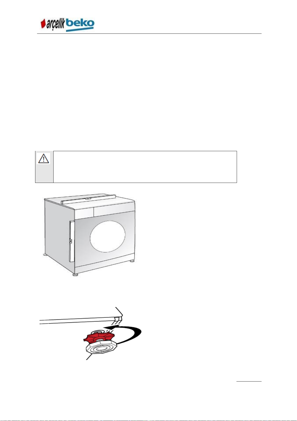
WARNING:
Before operating the washing machine, remove the transport
safety bolts! Otherwise, the product will be damaged.
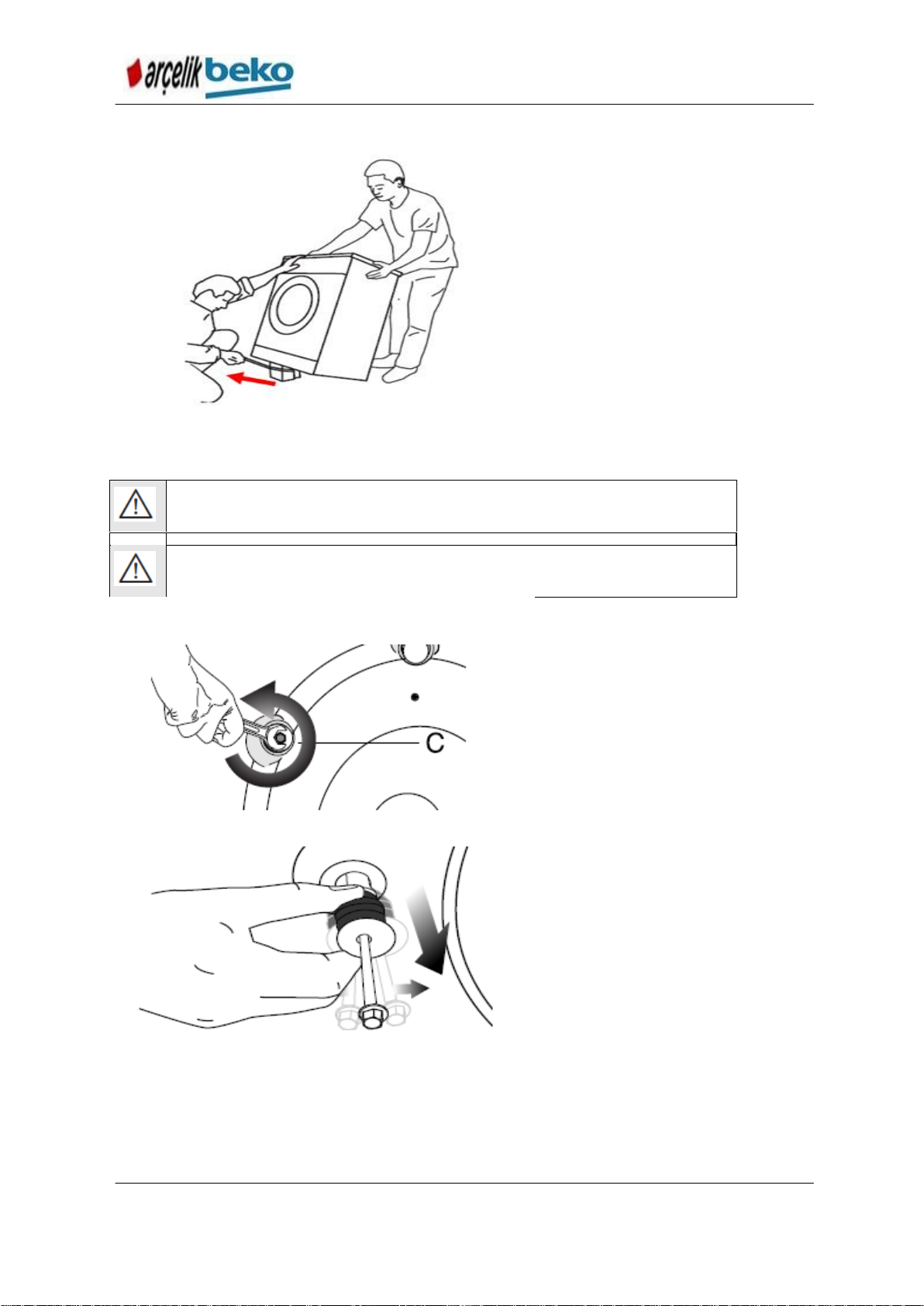
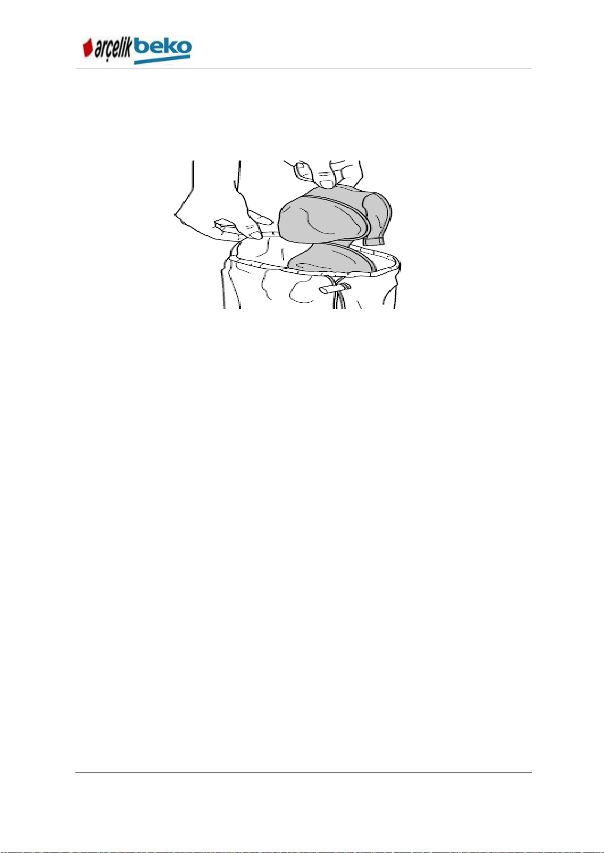
Tilt the machine backwards in
order to remove the package
support. Remove the
packaging reinforcement by
1. Loose all bolts with an
appropriate key until
they turn freely (C).
2. Remove transportation
safety bolts by turning
them gently.
4.2. Removing the Package Support
Figure 4.1
4.3. Removing the Transport Safety Bolts
Figure 4.2
Figure 4.3
10
Page 11
B13 B7S B7SLED WASHING MACHINE SERVICE HAND BOOK
Keep the transportation safety bolts in a safe place to reuse when the
washing machine needs to be moved again in the future.
Never transport the machine unless its transport safety bolts are installed!
Required water pressure is between 1-10 bar (0.1-1 MPa) for the proper
operation of the machine. For the healthy operation of the machine, 10 – 80
liters of water per minute should be supplied from a fully opened tap. If the
water pressure is higher, attach a pressure decrease valve.
If you will use the double water inlet product as a single water inlet
(cold)
,
before operating the product, make sure you insert the plug supplied with
the product to the hot water inlet. (It applies to the products with which blind
plug group is supplied.)
WARNING:
Single water inlet models should not be be connected to the hot
water tap. Laundry may be damaged or product may not operate according
to the protection status.
WARNING:
Do not use the old or used water inlet hoses for the new
product. It may leave stains on your laundry.
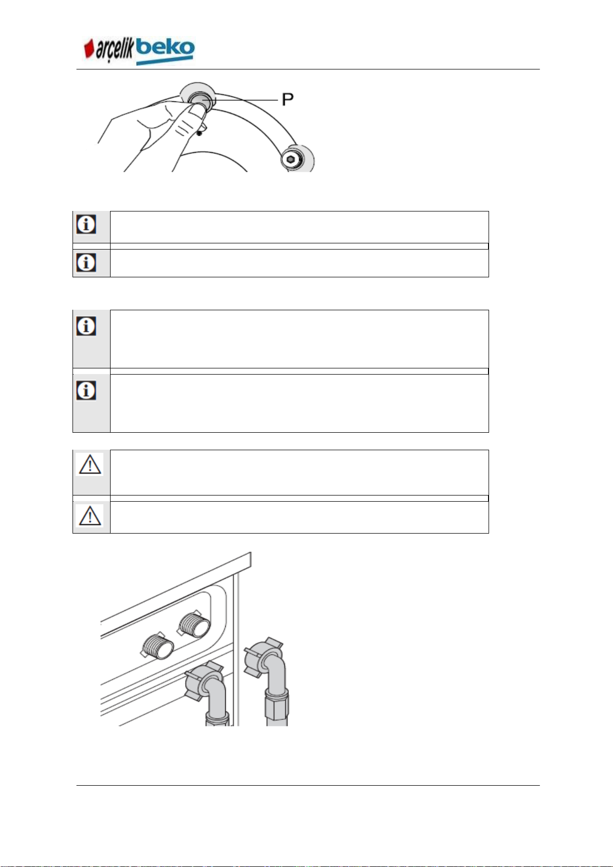
3. Attach the plastic covers
supplied in the User Manual
bag into the holes on the
rear panel. (P)
1. Connect the special hoses
supplied with the product to
the water inlets on the
product. Hose with red
inscriptions (left) (Max. 90
ºC) is for hot water inlet,
hose with blue inscriptions
(right) (Max. 25 ºC) is for
cold water inlet.
Figure 4.4
4.4. Connection to the Supply Water
Figure 4.5
11
Page 12
B13 B7S B7SLED WASHING MACHINE SERVICE HAND BOOK
WARNING:
Make sure that the hot and cold water taps are
connected correctly when the product is being installed. Your laundry
may come out hot at the end of the washing cycle and wear out.
WARNING:
If the hose is dislocated during water draining, it will flood
your house. Also, there is risk of burning by hot water due to washing at
high temperatures. In order to prevent such situations and make sure
that the machine performs water intake and discharge processes
without any problem, fix the drain hose securely.
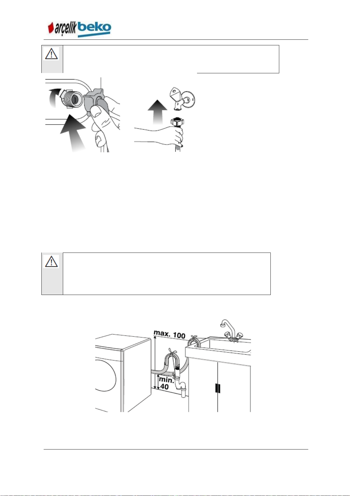
2. Tighten the nuts of the
hose by hand. Never
use a tool when
tightening the nuts.
Figure 4.6
3. When hose connection is completed, check whether there is leak problems at
the connection points by opening the taps fully. In case of any leakage, close
the tap and remove the nut. Check the seal and tighten the nut again carefully.
In order to prevent the water leaks and resultant damages, keep the taps
closed when you do not use the product.
4.5. Connection to the water drain
End of the drain hose should be attached directly to waste water drain, lavatory or
bathtub.
The hose should be attached to a height of at least 40 cm, and 100 cm at most.
Figure 4.7
12
Page 13
B13 B7S B7SLED WASHING MACHINE SERVICE HAND BOOK
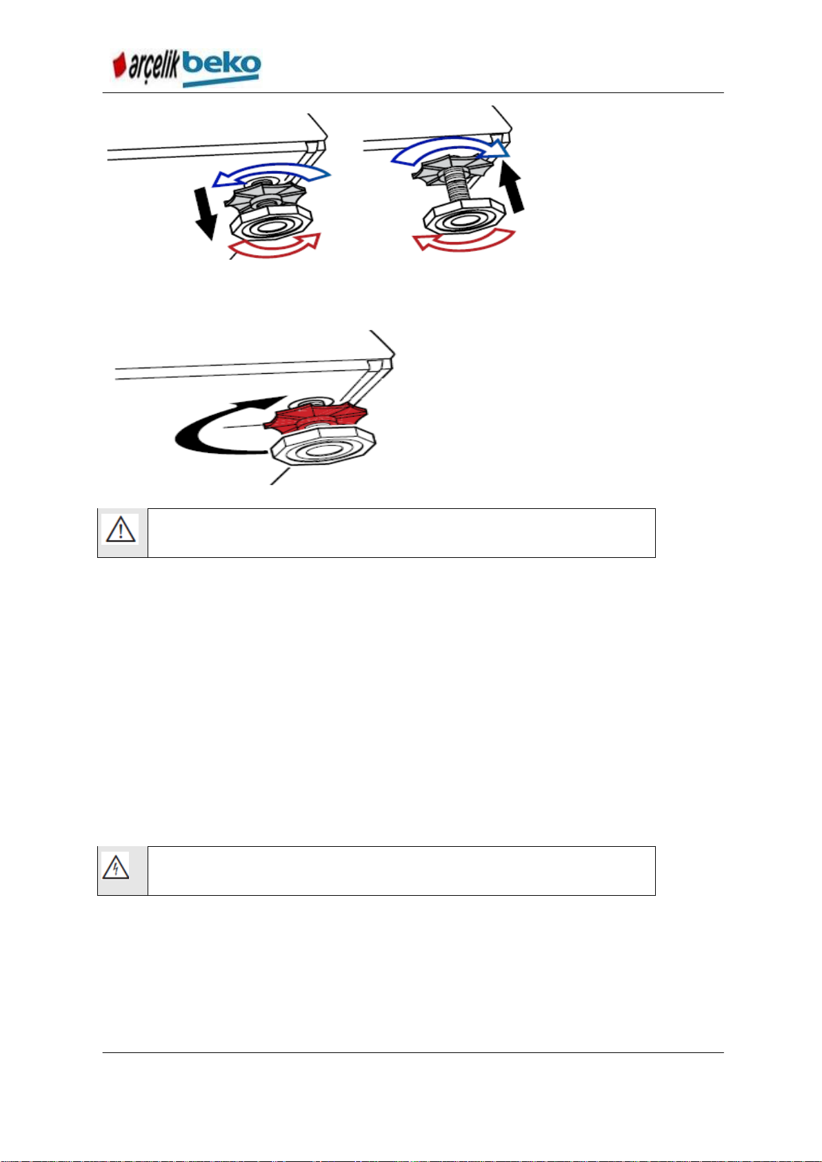
WARNING:
Product should stand on its legs stable and in a
balanced way in order for it to operate silently and without vibration.
Ensure balance by setting its legs. Otherwise, the product may move
from its place and cause crushing and vibration problems.
If the hose is placed at floor level or near to floor (less than 40 cm) and heightened
later on, water drain becomes difficult and laundry may come out extremely wet.
Therefore, follow the heights described in the figure.
To prevent the waste water to go back into the machine again and to ensure easy
drainage, do not immerse the end of the hose into the waste water or do not insert
it into the drain for more than 15 cm. Shorten it if it is longer than enough.
End of the hose should not be bent, it should be stepped on and Hose should not
be folded between the drain and the machine.
If the hose is not long enough, add the original extension hose to be supplied and
use it in this way. Hose cannot be longer than 3.2 m. In order to prevent water
leaks, fasten the extension hose and the drain hose of the product securely with a
clips to prevent any leak.
4.6. Adjustment of legs
Figure 4.8
1. Loosen the lock nuts on the feet by hand.
Figure 4.9
2. Adjust the legs until the product stands in a stable and balanced way.
13
Page 14
B13 B7S B7SLED WASHING MACHINE SERVICE HAND BOOK
WARNING:
Do not use any appliance or tool to loose the lock nuts.
Otherwise, they may be damaged.
WARNING:
Damaged power cables should be replaced by the
Authorized Service.
Figure 4.10
3. Tighten all lock nuts by hand again.
Figure 4.11
4.7. Electrical connection
Plug the product into a grounded outlet protected by a 16-ampere fuse. If the
machine is used without grounding which conform to the local regulations, our
company will not be liable for any damages which may arise.
Connection should comply with the national regulations.
Power cable's plug should be easily accessible after installation.
If the current value of your fuse is below 16 amperes, make a qualified electrician
connect a 16-ampere fuse.
Voltage specified in the “Technical specifications” section should match the mains
voltage.
Do not connect to the extension cables or multiple outlets.
4.8. Transportation of the product
1.
Before transporting the product, unplug it from the mains.
2. Remove the connections of water drain and water mains.
3. Discharge the entire amount of water left inside the product.
4. Install the transport safety bolts in reverse order of the disassembly procedure.
14
Page 15

B13 B7S B7SLED WASHING MACHINE SERVICE HAND BOOK
Never transport the machine unless its transport safety bolts are
installed!
WARNING:
Packaging materials may be dangerous for the children.
Keep the packaging materials out of the reach of the children.
15
Page 16
B13 B7S B7SLED WASHING MACHINE SERVICE HAND BOOK
5. Use of Product and Byproducts
5.1. Preparation
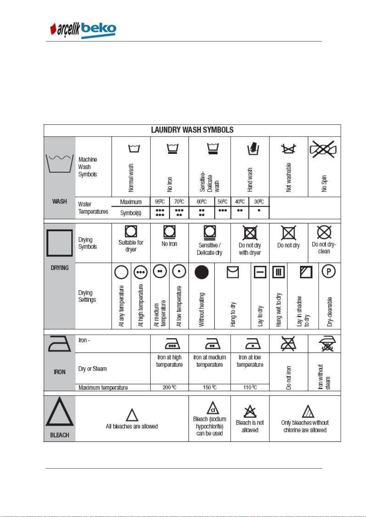
5.1.1. Sorting the Laundry
Sort laundry according to type of fabric, color, and degree of soiling and allowable
water temperature.
Always obey the instructions given on the garment tags.
Figure 5.1 Washing Symbols
16
Page 17
B13 B7S B7SLED WASHING MACHINE SERVICE HAND BOOK
5.1.2. Preparation of the garments to be washed
Laundry items which contain accessories such as support wire, buckle or metal
button may damage the washing machine. Remove the metallic parts or wash the
laundry by putting them into a bag or pillow case.
Figure 5.2
Remove all objects such as coins, pens, paper clips, etc. and reverse the pockets
and brush them. Such objects may damage the product or lead to sound problem.
Put the small size laundry items such as children socks or nylon socks into a
laundry bag or pillow case.
Place the curtains without squeezing them. Remove the curtain fittings.
Close the zips, sew the loose buttons, repair the tears and rips.
Wash the items at appropriate programs according to “Machine Wash” or “Hand
Wash” labels.
Do not wash the colored items with whites. New, dark color cotton garments may
release much dye. Wash them separately.
Tenacious stains should be handled appropriately before wash. If you are not
sure, check it with a dry cleaner.
Only use the dyes / color changers and descaling agents which are appropriate to
machine wash. Read the instructions on the packaging.
Wash the pants and delicates by reversing them.
Before washing the garments made of angora wool, wait them in the freezer
compartment of the refrigerator for a few hours. Thus, the tuft amount which may
be created will lessen.
Before putting the laundry items which are frequently exposed to substances such
as flour, lime powder, milk powder, etc., shake them well. Such dusts and
powders on the laundry may build up on the inner parts of the machine in time
and can cause damage.
17
Page 18
B13 B7S B7SLED WASHING MACHINE SERVICE HAND BOOK
WARNING:
Observe the information written in the "Program and
consumption table”. When it is overloaded, washing performance of the
machine will be decreased. Also, sound and vibration problems may occur.
Laundry type
Weight (g)
Bathrobe
1200
Napkin
100
Quilt cover
700
Bed sheet
500
Pillow case
200
Table cover
250
Towel
200
Hand towel
100
Night dress
200
Underwear
100
Men’s smock
600
Men’s shirt
200
Men’s pajamas
500
Blouse
100
5.1.3. Things to do for energy saving
Following information will help you use the product in an ecological and energy-
efficient manner.
Operate the machine with the highest capacity permitted by the program you
selected and do not over load it. See “Program and consumption table”.
Observe the temperature recommendations given on the detergent package.
Wash your slightly soiled laundry at low temperatures.
Prefer short programs for the slightly soiled and small amounts of laundry.
Do not use pre-wash and high temperatures for your laundry which are not
heavily soiled and stained.
If you will dry your laundry in a drier, select the highest spin speed which is
recommended for your washing program.
Do not use detergent in excess of the amount recommended on the detergent
package.
5.1.4. Correct load capacity
The maximum load capacity depends on the type of laundry, the degree of soiling
and the washing programme desired.
Machine automatically adjusts the water amount according to the weight of the
laundry put inside it.
Figure 5.3 Laundry weights
18
Page 19
B13 B7S B7SLED WASHING MACHINE SERVICE HAND BOOK
Loading door gets locked when operating. Door lock opens soon after the
program finishes.
WARNING:
If the laundry is placed wrongly, sound and vibration problems
may occur in the machine.
When using detergent, softener, starch, fabric dye, bleach or lime scale
remover; read the manufacturer's instructions on the package carefully and
follow the suggested dosage values. Use measuring cup if available.
5.1.5. Laundry loading
1. Open the laundry cover.
2. Put the garments into the machine in a loose manner.
3. Push and close the loading cover until you hear the locking sound. Make sure
that the garments do not get pinched between the door.
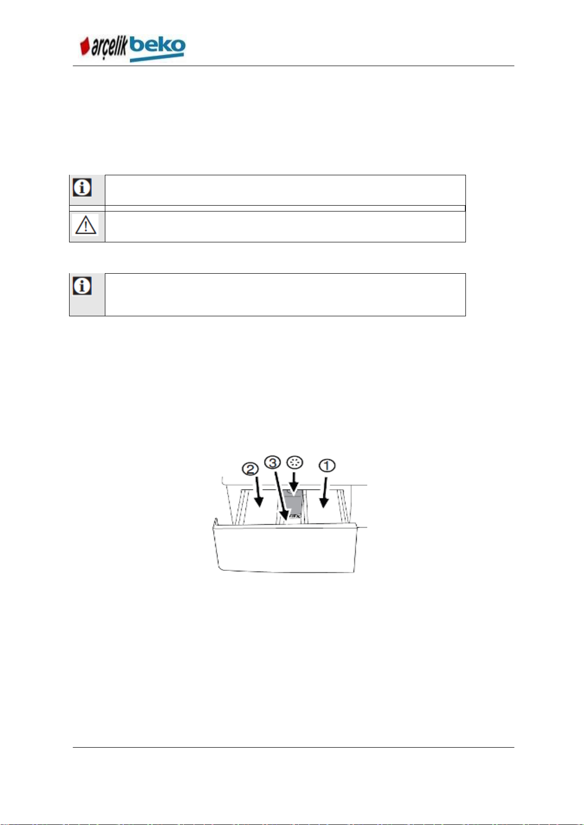
5.1.6. Use of detergent and softener
DETERGENT DISPENSER
Detergent dispenser consists of three compartments:
– (1) For prewash
– (2) For main wash
– (3) For softener
– (*) Moreover, there is a siphon part in the softener compartment.
Figure 5.4 Compartments of the detergent dispenser
DETERGENT, SOFTENER AND OTHER CLEANING AGENTS
Before starting the wash program, add detergent and softener.
While the washing cycle is in progress, do not leave the detergent dispenser
open!
If you are using a program without prewash, do not add detergent into the
prewash compartment (compartment number “1”).
In a prewash program, do not add liquid detergent into the prewash compartment
(compartment number “1”).
19
Page 20
B13 B7S B7SLED WASHING MACHINE SERVICE HAND BOOK
WARNING:
Only use the detergents which are intended and manufactured
for the washing machines.
WARNING:
Do not use soap powder.
If you are using detergent bag or dosage ball, do not select a prewash program.
Place the detergent bag or dosage ball directly among the garments in the
machine.
If you are using liquid detergent, do not forget to place the liquid detergent
container into the main wash compartment (compartment number “2”).
DETERGENT SELECTION
Detergent type to be used depends on the fabric type and color.
Use separate detergents for color and white laundry items.
Wash your delicate garments only with the special detergents which are used for
delicates (liquid detergent, wool shampoo, etc.).
You are recommended to use liquid detergent when washing dark color garments
or quilts.
Only wash the woolens with the special detergent used for woolens.
ADJUSTMENT OF DETERGENT AMOUNT
Amount of detergent to be used depends on the laundry amount, soil degree and
hardness of water.
Do not exceed the dosages which are recommended on the detergent package in
order to prevent the excessive foam and bad rinse results, to save detergent and
to protect the environment.
Use lower amounts of detergent for a small amount of laundry or slightly soiled
items.
USE OF SOFTENER
Put the softener into the softener compartment of the detergent dispenser.
Do not exceed the (>max<) level sign on the softener compartment.
If the softener lost its fluidity, dilute it with water before putting it into the
compartment.
USE OF LIQUID DETERGENTS
If the product has a liquid detergent container
Make sure that you place the liquid detergent container into the compartment
number “2”.
If the liquid detergent lost its fluidity, dilute it with water before putting it into the
detergent container.
20
Page 21
B13 B7S B7SLED WASHING MACHINE SERVICE HAND BOOK
Tablet detergents may leave a residue in the detergent compartment. If you
encounter such a problem, place the tablet detergent among the laundry
items at the bottom of the drum.
Use the tablet or gel detergent without selecting the prewash function.
Figure 4.5 Use of liquid detergent container
If the product does not have a liquid detergent container
In a prewash program, do not use liquid detergent for prewash.
Liquid detergent leaves stains on your items when delayed start function is used.
Do not use liquid detergent if you will use Delayed Start feature.
Use of gel and tablet detergent
Apply the following actions when using tablet, gel detergents, etc.
If the gel detergent is fluid and if your machine does not have a special liquid
detergent container, put the gel detergent into the main wash detergent
compartment during first intake of water. If your machine has a liquid detergent
container, fill the detergent into this container before starting the program.
If the gel detergent is not fluid or it is a capsule liquid tablet, put it directly into the
rum before starting the washing cycle.
Put the tablet detergents into the main wash compartment (number “2”) or directly
into the drum before starting the washing cycle.
Use of Soda
Put the liquid soda, powder soda or the fabric dye into the softener compartment.
In a wash program, do not put softener and soda at the same time.
After using soda, wipe the inside of the machine with a damp and clean cloth.
Use of bleach and decolorant
Add the bleach at the beginning of the washing cycle by selecting a prewash
program. Do not put detergent into the prewash compartment. As an alternative
application, add the bleach while the machine is taking water from the detergent
compartment in the first rinse step by selecting a program with additional rinse.
Do not use bleach by mixing it with detergent.
21
Page 22
B13 B7S B7SLED WASHING MACHINE SERVICE HAND BOOK
Use an anti-limescale suitable for the washing machines.
There might be a little amount of water left inside the product due to
the quality control procedures during manufacturing. It is not harmful
for the product.
Use a small amount of bleach (1/2 tea glass-approx. 50 ml) and rinse the laundry
well since bleach will cause skin irritation. Do not pour the bleach onto the laundry
and do not use it with the colored items.
When using oxygen-based decolorant, select a program which washes the
laundry at a low temperature.
Oxygen-based decolorant can be used with the detergent; however, if it is not at
the same consistence, first put detergent in the compartment number “2” in the
detergent dispenser and wait for the machine to flush the detergent when taking
in water. While the machine continues taking in water, add decolorant in the same
compartment.
Use of descaling agent
When it is necessary, only use the descaling agents which are intended and
manufactured for the washing machines.
5.1.7. First Use
Before starting to use the product make sure that the preparations are made which
are in line with the “Important Safety Instructions” and the instructions in the
“Installation” section.
In order to make the machine ready to wash laundry, perform the first washing cycle
with the Drum Cleaning program. If your machine does not have a Cauldron Cleaning
program. In order to make the machine ready to wash laundry, perform the first
washing cycle in line with the method which is described under the heading Cleaning
the Loading Door and Drum in section .
Figure 5.6 Cleaning the bellows
22
Page 23
B13 B7S B7SLED WASHING MACHINE SERVICE HAND BOOK
Speed Level
LEDs
Auxiliary
Function_1
LED i
Auxiliary
Function_2
LED i
Time Delay LEDs (3
LEDs as 3, 6, 9 hours)
or Auxiliary Function_3
LED i (1 LED)
2 or
16-position
(temperature
integrated)
Program
Selection
Switch
Temperature
Setting
Button (It
may not be
available in
Auxiliary
Function_1
Button
Auxiliary
Function_2
Button
Time Delay
Button or
Auxiliary
Function_3
Button
Start/Standby
button
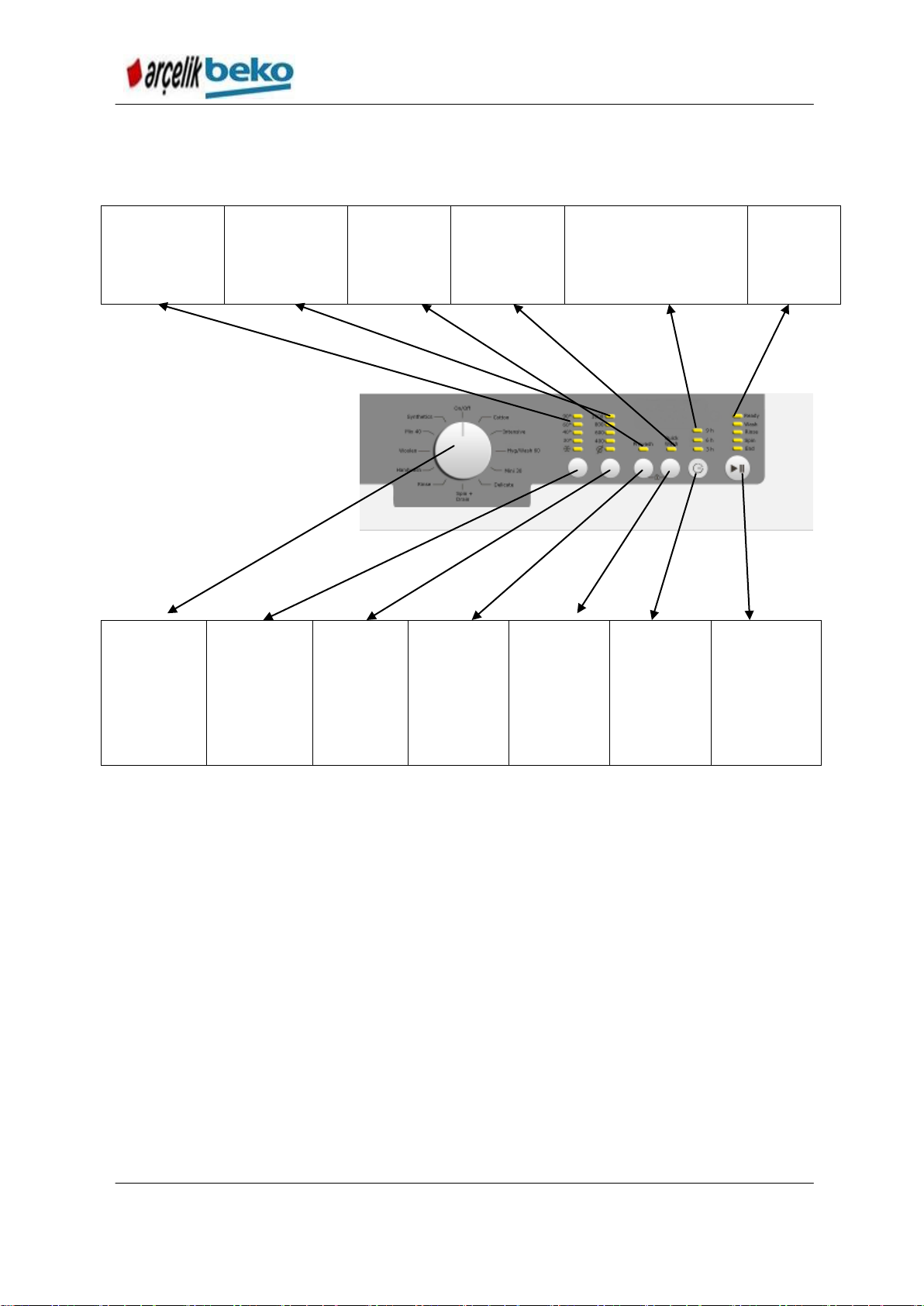
5.2. Control panel
B13 B7S Introduction of LED Control System
Figure 5.7 Control panel
1 - Program Selection knob (Uppermost position On / Off)
2 - Screen
3 - Delayed Start Indicator
4 - Program Follow-up indicator
5 - Start / Pause button
6 - Auxiliary Function buttons
7 - Spin Speed Adjustment button
8 - Temperature Adjustment button
23
Page 24
B13
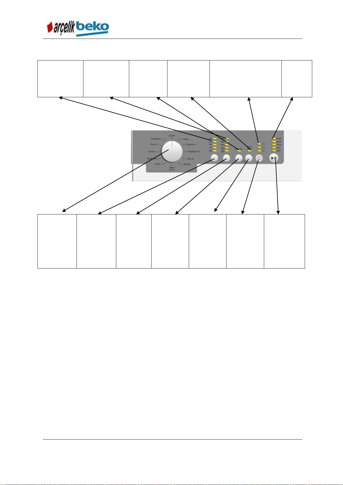
Speed Level
LEDs
Auxiliary
Function_1
LED i
Auxiliary
Function_2
LED i
Time Delay LEDs (3
LEDs as 3, 6, 9 hours) or
Auxiliary Function_3
LED i (1 LED)
2 or
16-position
(temperature
integrated)
Program
Selection
Switch
Temperature
Setting
Button (It
may not be
available in
Auxiliary
Function_1
Button
Auxiliary
Function_2
Button
Time Delay
Button or
Auxiliary
Function_3
Button
Start/Standby
button
B13 B7S B7SLED WASHING MACHINE SERVICE HAND BOOK
Introduction of LED Control System
B7S
Figure 5.8 Control panel
5.3. Preparing the Machine
1. Make sure that the hoses are secured tightly.
2. Plug in the machine.
3. Open the water tap fully.
4. Place the laundry inside the machine.
5. Add detergent and softener.
24
Page 25
B13 B7S B7SLED WASHING MACHINE SERVICE HAND BOOK
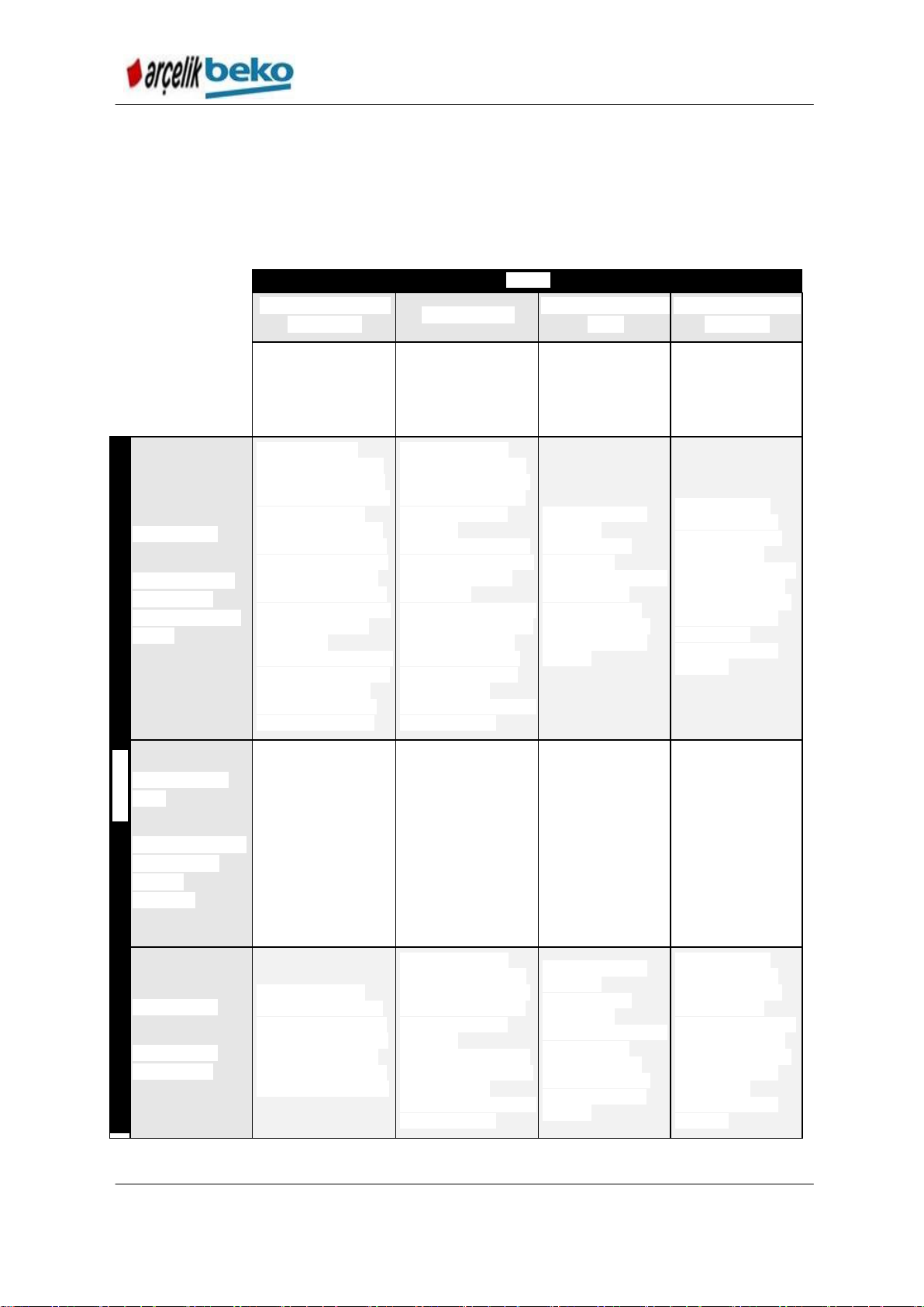
Clothes
Light Colored Items
and Whites
Colored Items
Black/Dark Colored
Items
Delicates/Woolens/
Silk Items
(Washing temperature
range recommended
for the soil amount:
40-90C)
(Washing temperature
range recommended
for the soil amount:
cold-40C)
(Washing
temperature range
recommended for
the soil amount:
cold-40C)
(Washing
temperature range
recommended for
the soil amount:
cold-30C)
Soil Amount
Heavily Soiled
(Tenacious stains
such as grass,
coffee, fruit, blood
stains.)
Prewash may be
necessary in order to
perform a preliminary
process for the stains.
Powder and liquid
detergents which are
recommended for the
whites can be used at
the doses which are
recommended for the
heavily soiled laundry.
It is recommended
that powder
detergents are used to
clean the stains which
are sensitive to the
decolorants and the
clay and soil stains.
Powder and liquid
detergents which are
recommended for the
colored items can be
used at the doses
which are
recommended for the
heavily soiled laundry.
It is recommended
that powder
detergents are used to
clean the stains which
are sensitive to the
decolorants and the
clay and soil stains.
Detergents not
containing decolorants
should be used.
Liquid detergents
which are
appropriate for
colored and
black/dark items can
be used at the
doses which are
recommended for
the heavily soiled
laundry.
Prefer the liquid
detergents which
are manufactured
for the delicate
laundry. Woolens or
silk clothes should
be washed with the
detergents which
are specially
manufactured for
woolens.
Normally Soiled
Items
(Body dirt stains at
the collars and
cuffs are
examples.)
Powder and liquid
detergents which are
recommended for the
whites can be used at
the doses which are
recommended for the
normally soiled
laundry.
Powder and liquid
detergents which are
recommended for the
colored items can be
used at the doses
which are
recommended for the
normally soiled
laundry. Detergents
not containing
decolorants should be
used.
Liquid detergents
which are
appropriate for
colored and
black/dark items can
be used at the
doses which are
recommended for
the normally soiled
laundry.
Prefer the liquid
detergents which
are manufactured
for the delicate
laundry. Woolens or
silk clothes should
be washed with the
detergents which
are specially
manufactured for
woolens.
Slightly Soiled
(There are not
visual stains.)
Powder and liquid
detergents which are
recommended for the
whites can be used at
the doses which are
recommended for the
slightly soiled laundry.
Powder and liquid
detergents which are
recommended for the
colored items can be
used at the doses
which are
recommended for the
slightly soiled laundry.
Detergents not
containing decolorants
should be used.
Liquid detergents
which are
appropriate for
colored and
black/dark items can
be used at the
doses which are
recommended for
the slightly soiled
laundry.
Prefer the liquid
detergents which
are manufactured
for the delicate
laundry. Woolens or
silk clothes should
be washed with the
detergents which
are specially
manufactured for
woolens.
5.4. Program selection and tips for correct washing
1. Select the programme suitable for the type, quantity and soiling degree of the
laundry in accordance with the "Programme and consumption table" and the
temperature table below.
2. Select any program you want to use by using Program Selection switch.
Table 5.1 Recommendations for correct washing
25
Page 26
B13 B7S B7SLED WASHING MACHINE SERVICE HAND BOOK
differ according to the model
of the machine.
5.5. Main Programs
Depending on the type of fabric, use the following main programs.
Cottons
Use this programme for your cotton laundry (such as bed sheets, duvet and
pillowcase sets, towels, bathrobes, underwear, etc.). Your laundry will be washed
with vigorous washing action for a longer washing cycle.
Synthetics
Use this programme to wash your synthetic clothes (shirts, blouses, synthetic/cotton
blends, etc.). Your laundry is washed with a softer washing movement and in a
shorter period of time.
You are recommended to use Synthetics 40˚C program for your curtains and tulle
curtains by selecting the prewash and crease reduction functions. Wash tulles by
putting a small amount of detergent into the main wash compartment since tulle
creates too much foam due to its porous structure. Do not put detergent into the
prewash compartment.
Woolens
You can wash your machine-washable woolen laundry at this program. Wash
your laundry by selecting an appropriate temperature written on its label. It is
recommended that you use appropriate detergent for woolens.
5.6. Additional programs
For special cases, additional programmes are available in the machine.
Cottons Eco
By washing normally soiled cotton and linen laundry in this programme, you can
ensure higher energy and water efficiency than other cotton programmes do. Actual
water temperature may be different from the stated wash temperature. When you
load the machine with less laundry (e.g. ½ capacity or less), programme time may
automatically get shorter in the later stages. In this case, energy and water
consumption will reduce for a more economic wash. This feature is provided in the
models with the remaining time indicator.
Delicate
Use it to wash your delicate laundry. It washes with a gentler action without any
interim spins compared to the Synthetics program. It should be used for laundry for
which sensitive wash is recommended.
Hand wash
Use this programme to wash your woolen/delicate clothes that bear “not machine-
washable” tags and for which hand wash is recommended. It washes laundry with a
very gentle washing action to not to damage clothes.
26
Page 27

B13 B7S B7SLED WASHING MACHINE SERVICE HAND BOOK
Use lower spin speeds for delicate laundries.
If the programme has not reached the heating step yet, you can
change the temperature without switching the machine to Pause
mode.
Mini
Use this programme to wash your lightly soiled cotton clothes in a short time.
Quick 14
Use this programme to wash your little amount of lightly soiled cotton clothes in a
short time. Your clothes will be washed at 30 ˚C in a short time like 14 minutes.
Dark colored items
Use this programme to wash your dark colored laundry or the laundry that you do not
want it get faded. Washing is performed by a low mechanical movement and at a low
temperature. Liquid detergent or wool shampoo are recommended for colored items.
Mix
Use this programme to wash your cotton and synthetic clothes together without
sorting them.
Shirts
Use this programme to wash the shirts made of cotton, synthetic and synthetic
blended fabrics together.
Sports
Use this programme to wash your garments that are worn for a short time such as
sportswear. It is suitable to wash little amount of cotton / synthetic blended garments.
5.7. Special programs
For specific applications, select any of the following programmes.
• Rinse
Use this programme when you want to rinse or starch separately.
• Spin+Pump
Use this programme to apply an additional spin cycle for your laundry or to drain the
water in the machine.
Before selecting this programme, select the desired spin speed and press Start /
Pause button. First, the machine will drain the water inside of it. Then, it will spin the
laundry with the set spin speed and drain the water coming out of them.
If you wish to drain only the water without spinning your laundry, select the
Pump+Spin programme and then select the No Spin function with the help of Spin
Speed Adjustment button. Press Start / Pause button.
5.8. Temperature selection
Whenever a new programme is selected, the maximum temperature for the selected
programme appears on the temperature indicator.
To decrease the temperature, press the Temperature Adjustment button.
Temperature will decrease gradually.
27
Page 28
B13 B7S B7SLED WASHING MACHINE SERVICE HAND BOOK
Some functions cannot b selected at the same time. For example,
Prewash and Quick Wash.
If an auxiliary function which is incompatible with the first selected
auxiliary function before the machine is operated, first selected
function will be cancelled and the last selected auxiliary function will
remain selected. For instance, if Prewash is selected first and then
Quick Wash is wanted to be selected, prewash becomes cancelled,
quick wash remains valid.
Auxiliary functions which are not compatible with the program
cannot be selected. (See “Program and consumption table”)
Auxiliary function buttons may vary according to the model of the
machine.
Prewash without detergent is recommended for tulle and curtains.
When you select this function, load laundry which is just the half of
the maximum laundry load specified in the program table.
When you select this function, load laundry which is just the half of
the maximum laundry load specified in the program table.
5.9. Auxiliary function selection
Select the auxiliary functions before starting the program. Furthermore, you may also
select or cancel auxiliary functions that are suitable to the running programme without
pressing the Start / Pause button when the machine is operating. For this, the
machine must be in a step before the auxiliary function you are going to select or
cancel.
If the auxiliary function cannot be selected or canceled, light of the relevant auxiliary
function will blink 3 times to warn the user.
Prewash
Prewash is necessary for heavily soiled laundry only. If you do not use a prewash
cycle, you save energy, water, detergent and time.
Quick
This function can be used for Cottons and Synthetics programs. If makes it possible
to shorten the wash time of the not very soiled laundry and decreases the rinse
number.
Extra rinse
This function will make sure that the machine performs an extra rinse in addition to
the rinse applied after the main program. Therefore, you can avoid the risk of
affecting the sensitive skins (baby skins, allergic skins, etc.) by the small amount of
leftovers on the laundry.
Extra water
This function makes sure that you wash and rinse your laundry at Cottons,
Synthetics, Delicates and Woolens programs with plenty of water. Use this function
for the delicate laundry which are easily creased.
28
Page 29
B13 B7S B7SLED WASHING MACHINE SERVICE HAND BOOK
CAUTION: Never wash your pets in the washing machine.
Do not use liquid detergents when you set Delayed Start! There is
risk of staining the laundry.
Additional laundry may be loaded during the delayed start period.
Crease reduction
This function ensures that the laundry is creased less when being washed. Drum
rotation movements are lessened and spinning speed is limited in order to reduce the
crease level. In addition to them, wash is performed at a high water level.
Rinse Hold
If you are not going to unload your clothes immediately after the programme
completes, you can use rinse hold function to keep your laundry in the final rinsing
water in order to prevent them from getting wrinkled when there is no water in the
machine. Press Start / Pause button after this process if you want to drain the water
without spinning your laundry. Programme will resume and complete after draining
the water.
If you want to spin the laundry held in water, adjust the Spin Speed and press Start /
Pause button.
Program will continue. Water is drained, laundry is spun and the programme is
completed.
Pet hair removal
This function helps to remove pet hair that remain on your garments more effectively.
When you select this function, Prewash and Extra Rinse steps are added to the
normal programme. Thus, washing is performed with more water (30%) and the pet
hair is removed more effectively.
Delayed Start
With the Delayed Start function the startup of the program may be delayed up to 19
hours. Delayed start time can be increased by increments of 1 hour.
1. Open the loading door, load the laundry and fill in detergent, etc.
2. Select the wash program, temperature, spinning speed and the auxiliary functions
if necessary.
3. Set the desired time by pressing the Delayed Start button.
4. Press Start / Pause button. The delayed start time you have set is displayed.
Delayed start countdown starts. “_” symbol next to the delayed start time moves up
and down on the display.
5. At the end of the countdown, duration of the selected programme will be displayed.
“_” symbol will disappear and the selected programme will start.
Changing the delayed start period
If you want to change the time during countdown:
1. Press Delayed Start button. Time will increase by 1 hour each time you press the
button.
2. If you want to decrease the delayed start time, press Delayed Start button
repeatedly until the desired delayed start time appears on the display.
29
Page 30
B13 B7S B7SLED WASHING MACHINE SERVICE HAND BOOK
If no programme is started or no key is pressed within 1 minute during
programme selection process, the machine will switch to Pause mode
and the illumination level of the temperature, speed and loading door
indicator lights will decrease. Other indicator lights and indicators will
turn off. Once the Programme Selection knob is rotated or any button is
pressed, indicator lights and indicators will turn on again.
If the Programme Selection knob is turned when the Child Lock is
active, "Con" appears on the display. The Child Lock does not allow
any change in the programmes and the selected temperature,
speed and auxiliary functions.
Even if another programme is selected with the Programme
Selection knob while the Child Lock is active, previously selected
programme
will continue running.
Canceling the Delayed Start function
If you want to cancel the delayed start countdown and start the programme
immediately:
1. Set the Delayed Start period to zero or turn the Programme Selection knob to
any programme. Thus, Delayed Start function will be canceled. The End/Cancel
light flashes continuously.
2. Then, select the programme you want to run again.
3. Press Start / Pause button to start the programme.
5.10. Starting the program
1. Press Start / Pause button to start the programme.
2. Programme follow-up light showing the startup of the programme will turn on.
5.11. Child Lock
You can prevent the children to play with the machine by means of the child lock
function. You can prevent any change to be effected for any program in progress by
activating this function.
To activate the Child Lock:
1st and 2nd Press the Auxiliary Function buttons for 3 seconds. The lights on the 1st
and 2nd Auxiliary Function buttons will flash while you keep the buttons pressed for
3 seconds, and "C03", "C02", "C01" will appear on the display respectively. Then,
"Con" will appear on the display indicating that the Child Lock is activated. If you
press any button or turn the Programme Selection knob when the Child Lock is
active, same phrase will appear on the display. The lights on the 1st and 2nd
auxiliary function buttons that are used to deactivate the Child Lock will blink 3 times.
To deactivate the Child Lock:
While any programme is running 1st and 2nd Press the Auxiliary Function buttons for
3 seconds. The lights on the 1st and 2nd Auxiliary Function buttons will flash while
you keep the buttons pressed for 3 seconds, and "C03", "C02", "C01" will appear on
the display respectively. Then, "COF" will appear on the display indicating that the
Child Lock is deactivated.
30
Page 31

B13 B7S B7SLED WASHING MACHINE SERVICE HAND BOOK
In addition to the method above, to deactivate the Child Lock,
switch the Programme Selection knob to On / Off position when no
programme is running, and select another programme.
Child Lock is not deactivated after power failures or when the
machine is unplugged.
If the machine does not pass to the spinning step, Rinse Hold function
might be active or the automatic unbalanced load detection system might
be activated due to the unbalanced distribution of the laundry in the achine.
If no change is allowed, the relevant light will flash for 3 times.
5.12. Progress of the Program
Progress of a running programme can be followed from the Programme Follow-up
indicator. At the beginning of every programme step, the relevant indicator light will
turn on and light of the completed step will turn off.
You can change the auxiliary functions, speed and temperature settings without
stopping the programme flow while the programme is running. To do this, the change
you are going to make must be in a step after the running programme step. If the
change is not compatible, relevant lights will flash for 3 times.
5.13. Lock of the loading door
There is a locking system on the loading door of the machine that prevents opening
of the door in cases when the water level is unsuitable.
Loading door light will start flashing when the machine is switched to Pause mode.
Machine checks the level of the water inside. If the level is suitable, Loading Door
light illuminates steadily within 1-2 minutes and the loading door can be opened.
If the level is unsuitable, Loading Door light turns off and the loading door cannot be
opened. If you are obliged to open the loading door while the Loading Door light is
off, you must cancel the current programme. See "Cancelling a Program".
5.14. Changing the selections after the program started
Switching the machine to pause mode
Press the Start / Pause button to switch the machine to pause mode while a
programme is running. The light of the step which the machine is in starts flashing in
the Programme Follow-up indicator to show that the machine has been switched to
the pause mode.
Also, when the loading door is ready to be opened, Loading Door light will also
illuminate continuously in addition to the programme step light.
Changing the auxiliary function, speed and temperature
Depending on the step the programme has reached, you can cancel or activate the
auxiliary functions. See "Auxiliary function selection".
Moreover, you can also change the speed and temperature settings. See “Speed
Selection” and “Temperature Selection”
Addition or removal of laundry
31
Page 32

B13 B7S B7SLED WASHING MACHINE SERVICE HAND BOOK
Depending on the step where the programme was canceled in, you
may have to put detergent and softener again for the programme
you have selected anew.
1. Press Start / Pause button to switch the machine to pause mode. The programme
follow-up light of the relevant step during which the machine was switched into the
pause mode will flash.
2. Wait until the Loading Door can be opened.
3. Open the Loading Door and add or take out the laundry.
4. Close the Loading Door.
5. Make changes in auxiliary functions, temperature and speed settings if necessary.
6. Press Start / Pause button to start the machine.
5.15. Cancellation of program
To cancel the programme, turn the Programme Selection knob to select another
programme. Previous programme will be cancelled. End / Cancel light will flash
continuously to notify that the programme has been canceled.
Pump function is activated for 1-2 minutes regardless of the programme step, and
whether there is water in the machine or not. After this period, your machine will be
ready to start with the first step of the new programme.
5.16. Program end
“End” appears on the display at the end of the programme.
1. Wait until the loading door light illuminates steadily.
2. Press On / Off button to switch off the machine.
3. Take out your laundry and close the loading door. Your machine is ready for the
next washing cycle.
5.17. There is a “Standby Mode” in your machine
After you switch on your machine with On-Off button, if no program is started or no
other procedure is performed at the selection step or no action is taken within approx.
2 minutes after the your selected program ends, your machine will switch to the
energy saving mode automatically. Brightness level of the indicator LEDs will be
decreased. Moreover, if there is a display on your product showing the program
duration, this display will turn off completely. If you turn the program switch or touch
any other button, LEDs and display will get back its original settings. Selections which
made while exiting the energy saving mode may change. Before you start the
program, check the accuracy of your selections. If necessary, repeat them. This is
not an error.
32
Page 33

B13 B7S B7SLED WASHING MACHINE SERVICE HAND BOOK
If water and softener more than a normal amount start to stay on the
softener compartment, siphon cleaning should also be performed.
6. MAINTENANCE AND CLEANING
Service life of product extends and frequently experienced problems will be reduced
if it is cleaned at regular intervals.
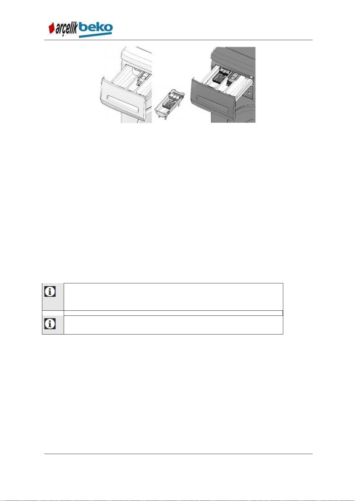
6.1. Cleaning the detergent dispenser
Clean the detergent drawer at regular intervals (every 4-5 washing cycles) as shown
below in order to prevent accumulation of powder detergent in time.
Figure 6.1 Cleaning the detergent compartment
1. Pull the detergent compartment towards yourself and remove it out by pushing
onto the marked point of the siphon on the softener compartment.
33
Page 34

B13 B7S B7SLED WASHING MACHINE SERVICE HAND BOOK
Repeat the drum cleaning work at every 2 months.
Use a descaling agent which is appropriate for the washing machines.
Rust stains may form inside the drum due to the metal objects. Clean the stains on
the surface of the boiler with stainless steel cleaning agents. Never use steel wool or
wire wool.
WARNING:
Never use sponge or scrub materials. These will damage the painted and
plastic surfaces.
2. Wash the dispenser and the siphon in the lavatory with an ample amount of
lukewarm water. In order to prevent the residues to contact your skin, clean it with
an appropriate brush by wearing a pair of gloves.
3. After the cleaning, replace the dispenser in order to make sure that the siphon is
seated into its place well .
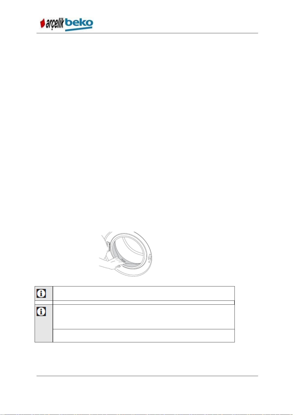
6.2. Cleaning the Loading Door and the Drum
Softener, detergent and dirt residues may accumulate in your machine in the course
of the time and lead to complaints of odor and bad wash results. To prevent this, use
Drum Cleaning
program. If your machine does not have
use the Cottons-90 program by selecting the Extra
Water
Drum Cleaning
or
Extra Rinse
program,
auxiliary
function. Run these processes definitely without any laundry and when the machine
is empty. Before starting the program, put one teaspoon (max. 100 g) powder
descaling agent into the main wash detergent compartment (number 2). If the
descaling agent is a tablet, put one tablet into the compartment number 2. After the
program finishes, wipe dry the inside of the bellows with clean cloth.
Make sure that there is not any foreign bodies left inside the drum after each wash.
Figure 6.2 Cleaning the bellows
If the holes in the bellows shown in the Figure are clogged, open the holes by means
of a toothpick.
6.3. Cleaning the body and control panel
Wipe the body of the machine with soapy water or non-corrosive mild gel detergents
as necessary, and dry with a soft cloth.
34
Page 35

B13 B7S B7SLED WASHING MACHINE SERVICE HAND BOOK
WARNING:
Foreign objects which stay inside the pump filter may damage your
machine or cause noise problem.
WARNING:
If the product is not being used, tap should be shut, mains pipe should be
removed and the water inside the machine should be emptied against any likely
freezing.
WARNING:
Shut the tap which the mains pipe of the product is connected to after
each use.
Use only a soft and damp cloth to clean the control panel.
6.4. Cleaning the water inlet filters
There is a filter at the end of each water intake valve at the rear of the machine and
also at the end of each water intake hose where they are connected to the tap.
These filters prevent the foreign substances and dirt in the supply water to enter into
the machine. Filters should be cleaned when they become dirty.
Figure 6.3
1. Shut the taps.
2. Remove the nuts of the water inlet hoses and clean the sediments on the filters of
the water inlet valves with an appropriate brush. If the filters are too dirty, remove
them from their places with a pliers and clean in this way.
3. Remove the filters on the flat end of the water inlet hoses along with their seals
and wash them under running water well.
4. Replace the seals and filters carefully and tighten their nuts by hand.
6.5. Draining the remaining water and cleaning the pump filter
The filter system in your machine prevents solid items such as buttons, coins and
fabric fibers clogging the pump impeller during discharge of washing water. Therefore
the waste water is discharged without any problems and the service life of the pump
is increased.
If the machine does not drain the water, pump filter may have been clogged. Filter
should be cleaned when clogged or once in 3 months. In order to clean the pump
filter, first the water should be drained.
Also, before transporting the machine (for example when moving to new house) and
when the water has the risk of freezing, water may have to be fully drained.
35
Page 36

B13 B7S B7SLED WASHING MACHINE SERVICE HAND BOOK
WARNING:
Temperature of the water inside the machine may rise up to 90 ºC. In
order to avoid the burning risk, filter should be cleaned after the water inside the
machine is cooled down.
In order to clean the soiled filter and drain the water:
1. Unplug the machine and disconnect the power.
2. Open the filter cover.
Figure 6.4 Cleaning the filter - 1
3. Some of our products have emergency draining hose and some do not have.
Follow the steps below to discharge the water.
Discharging the water when the product has an emergency draining hose:
Figure 6.6 Cleaning the pump - 2
a. Pull away the emergency water draining hose from its housing.
b. Put the larger end of the hose into a large vessel. Pull and remove the plug at the
end of the hose and drain the water into a vessel. When the vessel is full, shut the
nozzle of the hose by inserting the plug into it. After you empty the vessel, repeat
above procedures and drain the water inside the machine fully.
c. When the water drainage is complete, block its nozzle again with the plug and
secure the hose into its place.
36
Page 37

B13 B7S B7SLED WASHING MACHINE SERVICE HAND BOOK
Figure 6.6 Cleaning the pump filter - 3
d. Turn and remove the pump filter.
Discharging the water when the product does not have an emergency draining
hose:
Figure 6.7 Cleaning the pump filter - 4
Figure 6.7 Cleaning the pump filter - 5
a. In order to collect the water to flow out of the filter, place a large vessel in front of
the filter.
b. Turn and loosen the pump filter until water starts to flow (counterclockwise). Fill
the flowing water into the vessel which you put in front of the filter. Always keep a
piece of cloth handy to absorb any spilled water.
37
Page 38

B13 B7S B7SLED WASHING MACHINE SERVICE HAND BOOK
c When the water in the machine ceases, turn the pump filter and remove it fully.
4. Clean the residues inside the filter as well as the lint, if any, around the propeller.
5. Replace the filter.
6. Close the filter cap by pressing on the place of the tab.
38
Page 39

B13 B7S B7SLED WASHING MACHINE SERVICE HAND BOOK
B13 B7S WATER ALGORITHM
NUMBER OF
VALVE
OPENIN
G = 1
NOTE:
AFTER A PROGRAM CANCEL;
1-IF THE PROGRAMME CANCELLATION IS AFTER
THE "1SEC PUMP" AT THE TOP CLOSING STEP,
NO TOP CLOSING WILL BE MADE IN THE NEWLY
SELECTED PROGRAMME, IT WILL INTAKE
WATER IN MOTION.
2-) IF THE PROGRAMME CANCELLATION IS MADE
DURING "10 SEC WATER INTAKE FROM
PREWASH VALVE" THEN IN THE NEW SELECTED
PROGRAMME WATER INTAKE WILL BE MADE UP
TO THE P1 LEVEL; WITHOUT TOP CLOSING FROM
THE MAIN WASH VALVE, WITHOUT MOTION AND
MAKING LEVEL CHECKS.
NOTE:
FOR ALL PROGRAMMES N = 5 and M = Infinite 20
NUMBER OF VALVE
OPENING = 2
NUMBER_OF_VALVE_OPENING = M
NUMBER_OF_VAL
VE_OPENING = N
NUMBER OF VALVE
OPENING = 1
NUMBER OF VALVE OPENING = 3
NUMBER OF VALVE
OPENING = 2
TOP CLOSING
CONDITIONS FOR HOT WATER INTAKE
• Hot water intake from hot water valve is applicable at temperatures at 60
or higher.
• During hot water intake, if the machine is turned off and on, the water
should be filled through the cold water valve making level checks and
without a motor movement.
• During hot water intakes, when the water temperature reaches (target
temperature - 5), the hot water valve should be shut off and continued
with the cold water valve.
7. . GENERAL OPERATING PRINCIPLE
7.1. Water Intake Profile
Figure 7.1 Water intake graphic
39
Page 40

B13 B7S B7SLED WASHING MACHINE SERVICE HAND BOOK
TOP CLOSURE ALGORITHM
Is main wash at the
beginning of the step?
Take water from
CV1 for 6 seconds
Yes
Drain for 1 second
Wait for 2 seconds
No water test
Wait for 10
seconds
END
Top closure algorithm is not applied
under following conditions:
If previous programme is
cancelled and a new programme
started, top closure algorithm is
not applied in the newly selected
programme.
1. Water intakes in all programmes are realized by water level sensor. Whether
or not the water level has dropped below levels determined according to the
steps is checked by the water level sensor. If the water level has dropped,
water will be intaken against checking the the water level sensor.
2. Top closure algorithm is applied during programme startup.
Figure 7.2 Top closure algorithm
3. Later water intakes are realized according to the levels determined according
to the programmes. If the selected programme temperature is 60C or higher
than 60C, water intakes are made via hot water valve. Otherwise, water is
taken through cold water valve.
4. Amount of load in the machine is determined according to number of valve
opening in this step. Max. water intake number may change according to
energy declaration target.
Depending on the low, medium or high load, washing parameters such
as heating step time, rinse water amount are changed.
5. When water level drops below Psafety (Pg) level in washing steps during and
after heating, heater is turned off. Water is taken from the main wash valve.
40
Page 41

B13 B7S B7SLED WASHING MACHINE SERVICE HAND BOOK
7.2. Heating Profile
Hysteresis profile is used for all programmes.
Information about the amount of hysteresis according to the programme is included in
the variable file.
In programmes where there is risk of damaging textiles such as woolens or hand
wash, hysteresis value is maintained high. For this reason, heating profiles of these
programmes can be seen as hysteresis. However, under bad conditions like very low
water inlet temperature, hysteresis can be seen.
Figure 7.3 Graphic for heating with hysteresis
Once the machine reaches the max. set temperature (Tset) for the machine, heater is
deactivated, but remains in heating step.
When temperature drops in the amount determined in the software, (T) heater is
reactivated.
This process goes on until the time designated for heating step is completed (tx).
When heating profile with hysteresis is used, adverse affecting possibility of max.
reached temperature by the following is minimized:
Input temperature of water lower than ambient temperature,
Low input voltage,
Excessive water intake by the machine,
Adding water from the detergent dispenser.
7.3. Anti-foaming Profile
Following profile is used to decrease foaming at the end of main wash:
41
Page 42

B13 B7S B7SLED WASHING MACHINE SERVICE HAND BOOK
Discharge the water inside the machine after main washing step is finished. (If
additional water is taken without discharging water, foam overflow will occur.)
o Movement in discharging 80 rpm – 12 s on – 10 s off)
Wait 2 sec.
Intake water by time. (10 s; may vary according to control systems.)
Wash for 5 min. in woolen washing percentage. (to extinguish foam)
o Movement 30 rpm – 3 s on – 80 s off)
Discharge the water and continue with main wash end spin.
o Movement in discharging 80 rpm – 12 s on – 10 s off)
7.4. Foam Detecting and Extinguishing Algorithm
If foaming occurred in the machine is determined by water level check during spin; if
foam occurred, profile is applied to extinguish and discharge.
If the measured level is higher than the determined foam level;
o Motor is stopped for 280 s, (motionless waiting)
o Water is taken for 4 s,
o Motor is stopped for 30 s, (motionless waiting)
o Psafety 4 + 6 s pumping performed.
o Water is taken for 4 s,
o Motor is stopped for 30 s, (motionless waiting)
o Psafety 4 + 6 s pumping performed.
o Water is taken for 4 s,
o Motor is stopped for 30 s, (motionless waiting)
o Psafety 4 + 6 s pumping performed.
o Spinning starts again.
This control is repeated 3 time in each spin.
If the foam level is still high at the end of all 3 trials, spin is skipped to switch to
the next step.
Extra rinse is determined according to the number of foam detecting.
o If 1-2-3, 1 rinse,
o If 4-5, 2 rinses,
o If more than 5, 3 rinses are added.
If the foam level is still high after trying 3 times in the last spin step,
programme is finished without spinning.
42
Page 43

B13 B7S B7SLED WASHING MACHINE SERVICE HAND BOOK
TIME
VALVE
TEMPERATURE
SPIN SPEED
STEPS
NA
NA
Check up
2
NA
Drain
15'
Prewash Valve
prewash
2'
NA Drain
10''
Prewash Valve
Top Closure
15'
Main Wash Valve
Cold washing
10'
Main Wash Valve
Soaking
60
Main Wash Valve
Soaking
5'-60'
Main Wash Valve
Heating
5'
Main wash valve
Washing after heating
5'
Main wash valve
Warming up
2
NA
Drain
5'
Main Wash
Valve
Intermediate Spin
5'
Prewash valve
Rinse 1
2'
Main wash
valve
Drain
5'
Main wash
valve
Intermediate Spin
5'
Prewash Valve
Rinse
2'
Main wash
valve
Drain
5
Main wash
valve
Intermediate Spin
5'
Prewash Valve
Rinsing Extra
2
Main wash
valve
Drain
Main wash
valve
Intermediate Spin
5
Main wash
valve
Rinsing Foam
2
Main wash
valve
Drain
5'
Main wash
valve
Intermediate Spin
5'
Pre & Main
wash valve
Softener
NA
NA Soaking
2'
Main wash
valve
Drain
3'
Main wash
valve
Preliminary Intermediate
Spinning
7.5. Programme Flows
43
Page 44

B13 B7S B7SLED WASHING MACHINE SERVICE HAND BOOK
1
5
'
NA Final Spin
END END
END
END
Programme steps
Cottons Eco
Cottons
Synthetics
Delicate
Woole
ns
Cottons Eco
Cottons
Synthetics
Finishing
Protection
Woole
ns
Wash Steps
Control
Drain
Prewash
If prewash
auxiliary function
is selected
If prewash
auxiliary
function is
selected
If prewash
auxiliary
function is
selected
If prewash
auxiliary
function is
selected
Drain
If prewash
auxiliary function
is selected
If prewash
auxiliary
function is
selected
If prewash
auxiliary
function is
selected
If prewash
auxiliary
function is
selected
Top Closure
Cold washing
Soaking
If soaking
auxiliary function
is selected
Heating
Washing after
heating
Warming up
If the selected
temperature is
>= 60° or >=
40°C and
anticreasing
auxiliary
function is
selected, then
water will be
intaken.
If the selected
temperature is
>= 60° or >=
40°C and
anticreasing
auxiliary
function is
selected, then
water will be
intaken.
Water will be
intaken at all
conditions.
Drain
Intermediate Spin
Rinse 1
Drain
Intermediate Spin
Rinse 2
At full load;if
Tset=60C then
step will be
bypassed if Tset
= 40C then step
will be run. At
half load;if
Tset=60C then
step will be
bypassed. If
Tset=40C then
step will be run.
Wash
Steps
Programme steps
Cottons Eco
Cottons
Synthetics
Delicate
Woolen
s
Cottons Eco
Cottons
Synthetics
Finishing
Protection
Woolen
s
Figure 8.4 Programme flow example
44
Page 45

B13 B7S B7SLED WASHING MACHINE SERVICE HAND BOOK
Drain
At full load;if
Tset=60C then
step will be
bypassed if Tset
= 40C then step
will be run. At
half load;if
Tset=60C then
step will be
bypassed. If
Tset=40C then
step will be run.
Intermediate Spin
At full load;if
Tset=60C then
step will be
bypassed if Tset
= 40C then step
will be run. At
half load;if
Tset=60C then
step will be
bypassed. If
Tset=40C then
step will be run.
Extra rinse pilot
pump
ıf extra rinse
auxiliary function
is selected
Rinsing Extra
ıf extra rinse
auxiliary function
is selected
ıf extra rinse
auxiliary
function is
selected
ıf extra rinse
auxiliary
function is
selected
ıf extra
rinse
auxiliary
function is
selected
Drain
ıf extra rinse
auxiliary function
is selected
ıf extra rinse
auxiliary
function is
selected
ıf extra rinse
auxiliary
function is
selected
ıf extra
rinse
auxiliary
function is
selected
Intermediate Spin
ıf extra rinse
auxiliary function
is selected
ıf extra rinse
auxiliary
function is
selected
ıf extra rinse
auxiliary
function is
selected
Rinsing Foam
If foam is
detected
If foam is
detected
If foam is
detected
If foam is
detected
If foam is
detected
Drain
If foam is
detected
If foam is
detected
If foam is
detected
If foam is
detected
If foam is
detected
Intermediate Spin
If foam is
detected
If foam is
detected
If foam is
detected
If foam is
detected
Softener pilot pump
Softener
Soaking
If soaking is
selected
If soaking is
selected
If soaking
is
selected
Drain
Preliminary
Spinning
Final Spin
Pump
45
Page 46

B13 B7S B7SLED WASHING MACHINE SERVICE HAND BOOK
Programme
steps
Hand Wash
Shirts
Rinse
Spinni
ng
Mini 14
Mini
AquaPerfec
t
Hand Wash
Cottons
Rinse
Spinni
ng
Mini 14
Mini
40°C 40
min
Wash Steps
Control
Drain
Prewash
If prewash
auxiliary
function is
selected
Drain
If prewash
auxiliary
function is
selected
Top Closure
Cold washing
Soaking
Heating
Washing after
heating
Warming up
If the
selected
temperatu
re is >=
60° or >=
40°C and
anticreasi
ng
auxiliary
function is
selected,
then water
will be
intaken.
If selected
temperatu
re is
>=60°C
water will
be
intaken.
Drain
Intermediate
Spin
Rinse 1
Drain
Intermediate
Spin
Rinse 2
46
Page 47

B13 B7S B7SLED WASHING MACHINE SERVICE HAND BOOK
Programme
steps
Hand
Wash
Shirts
Rinse
Spi
nni
ng
Mini 14
Mini
AquaPerfec
t
Hand
Wash
Cottons
Rinse
Spi
nni
ng
Mini 14
Mini
40°C 40
min
Drain
Wash Steps
Intermediate
Spin
Extra rinse pilot
pump
ıf extra
rinse
auxiliary
function is
selected
Rinsing Extra
ıf extra
rinse
auxiliary
function is
selected
ıf extra rinse
auxiliary
function is
selected
ıf extra
rinse
auxiliary
function is
selected
ıf extra rinse
auxiliary
function is
selected
ıf extra rinse
auxiliary
function is
selected
Drain
ıf extra
rinse
auxiliary
function is
selected
ıf extra rinse
auxiliary
function is
selected
ıf extra
rinse
auxiliary
function is
selected
ıf extra rinse
auxiliary
function is
selected
ıf extra rinse
auxiliary
function is
selected
Intermediate
Spin
ıf extra rinse
auxiliary
function is
selected
ıf extra
rinse
auxiliary
function is
selected
ıf extra rinse
auxiliary
function is
selected
ıf extra rinse
auxiliary
function is
selected
Rinsing Foam
If foam is
detected
If foam is
detected
If foam is
detected
If foam is
detected
Drain
If foam is
detected
If foam is
detected
If foam is
detected
If foam is
detected
Intermediate
Spin
If foam is
detected
If foam is
detected
If foam is
detected
Softener pilot
pump
ıf extra
rinse
auxiliary
function is
selected
Softener
Soaking
If soaking is
selected
If soaking
is selected
If soaking is
selected
If soaking is
selected
If soaking is
selected
Drain
Preliminary
Spinning
Balanced Load
Spinning
Final Spin
Pump
47
Page 48

B13 B7S B7SLED WASHING MACHINE SERVICE HAND BOOK
8. COMPONENT WORKING PRINCIPLES
8.1. Electronic Control and Visual Card
By means of the control and visual card which is designed to have a single face and
manufactured by ARÇELİK; the wash programs which are written onto the
microprocessor, washing and spinning motor profiles, protection algorithms and
components (motor, heater, pump, valves, door safety lock, ntc, water level selection
switch, spinning/temperature selection potentiometer) are controlled.
There are feeding circuit on the front face of the card (smps), motor and other
component control circuits -triac and relays - and component connection terminals
and on its rear face there are microprocessor, function and time delay button and
LEDs and program tracking LEDs.
Necessary wash program is operated in line with the information read from the
program selection switch which is connected to the card (rotary switch),
spinning/temperature setting potentiometer, auxiliary function and Time Delay
switches.
From the card, auxiliary function, speed/temperature and time delay options and
functions can be selected.
Picture 8.1 Conrol kartı
48
Page 49

B13 B7S B7SLED WASHING MACHINE SERVICE HAND BOOK
Rated Operating Voltage : 250V 50-60Hz
Operating Current : 10-50 mA
PTC Resistance : Min. >=50 ohm
Contact Locking time : <=8s
Contact Engaging time : 35...70s
Operating Temperatures : T85
8.2. Safety Switch (Door Lock)
Picture 8.2 Safety switch
PTC door safety lock was used. When any wash program is started after the door is
closed, PTC disk is heated and the door is locked and it is prevented to be opened
when the program is in progress.
After the program finishes, PTC cools down in 70s and the door is unlocked.
Current of all components passes over the door safety lock. Machine will not work in
case it is faulty.
When 220V is supplied between the contacts numbered 3 and 1, the distance
between the contacts numbered 3 and 2 should switch to closed position.
8.3. Motor
Universal series motor is used. Universal series motor consists of stator and rotor.
Stator and rotor windings are connected in series by means of collector and brush
and current is transmitted to the rotor windings. Motor speed control is made over
electronic card. Motor triac on the card adjusts the motor/drum speed by changing
the triac triggering angle according to the signal coming from the tacho. In case of
abnormal situations (continuous operation-locked rotor), thermocouple is available on
the motor winding to protect the winding from overheating.
Rated Operating Voltage 220-240V 50-60Hz
Current 6A max (washing) / 3A (spinning)
Input Power 300 / 450 W
Starting Current 5...8A (washing) / 10A max (spinning)
Technical specifications of tachogenerator
Number of double pole 8
Tacho output voltage at 300 rpm >0.9 V
Tacho output voltage at 16500 rpm <45 V
49
Page 50

B13 B7S B7SLED WASHING MACHINE SERVICE HAND BOOK
Rated Voltage 220-240 V 50Hz
Resistance 145 ohm
Current <0.2A
Flow >14 l/min
Starting performance <=4s (160V)
Operating Voltage : 230VAC 50-60 Hz
Power : 1950W
Resistance : 26W ± 3
When the resistance is measured from both
ends with multimeter, approx. 26 should be
read.
Picture 8.3. Motor
8.4. Heater
It is used to heat the water inside the drum.
Since it is an electronically controlled machine, there is a double thermocouple at
each of the heater inlets.
When the heater operates dry, the overheated thermocouple open circuits the heater.
Open circuited heater cannot be used again. In order to prevent the heater to
operate without water “during heating”, heater safety water level is defined to the
microprocessor (Psafety). When the water level which is measured by the water level
sensor comes under the defined Psafety level, heater is disabled.
When the water temperature which is read by NTC reaches to the “selected
temperature”, heater is disabled by the microprocessor.
Picture 8.4 Heater
8.5. Valve
There is 2-way valve in the models which have a single water inlet and there is 2-way
valve and extra single valve in the hot-water inlet machines. Valves are driven by the
triacs on the electronic board; and they are driven with both valves in the softener
step by use of crashed water directing system and the water is directed to the
medium compartment of the detergent dispenser.
Rated Voltage 220-240 V 50/60 Hz
Rated Power 5-8 W
Winding Resistance 3400-4500 ohm
Flow 10 l/min
8.6. Drain Pump
It is a synchronous motor equipped with a mono-phase bipolar magnet rotor. At the
draining step, electronic control card is activated by the triac on it. It is protected by
impedance for continuous operation and blocking situation of the rotor.
Drain pump drains the water inside the drum.
Picture 8.5 Drain pump
50
Page 51

B13 B7S B7SLED WASHING MACHINE SERVICE HAND BOOK
Temperature
(oC)
Nom. Resistance RNom
(Ω)
-10
26424
-5
20205
0
15589
5
12119
10
94-99
15
74-9 S
20
5962
25
4773
30
3346
35
3118
40
2544
45
2037
50
1721
55
1428
60
1190
65
996.9
70
839
75
709.4
80
602.4
85
513.7
90
439.9
95
373.1
100
326.3
Resistance (25 C) : 4773 ohm (4.2%, Siemens) 4837 ohm (3.2%, elth)
Operating Temperature : -10C...+100C
Thermal time constant : 16 2 s
Resistance values which are read from the NTC ends by
means of multimeter are compared to the below table. These
approximate values should be read.
8.7. Ntc
It is a component which is used to measure the water temperature inside the drum
and resistance of which decreases when the temperature increases.
When the water temperature reaches to the adjusted temperature, heater is disabled
by means of the heater relay on the card.
Picture 8.6 NTC
Table 8.1 NTC values
8.8. Water Level Sensor
An analog water level sensor which is fed by 5 V voltage is used. This sensor
ensures that the water level is determined instantly with the frequency values which it
generates against the pressure created. There are frequency values corresponding
to the all pressure values. An infinite number of levels can be determined in the
analog water level sensor. Water levels change according to the wash criteria of the
designed program depending on the selected program, temperature and auxiliary
function.
Analog water level sensors are pressure – displacement inverter components in
general.
Analog water level sensors generate frequency modulation as output.
51
Page 52

B13 B7S B7SLED WASHING MACHINE SERVICE HAND BOOK
Cable inputs
5VDC / Data / GND.
Operating Voltage : 5 VDC
When it is empty, 625 ± 2 Hz frequency value should
be read from the Data and GND terminals.
There are basically 2 capacitors, 1 coil and an inverter circuit on itself or the control
system to which it is connected.
Pressure increase pushes a ferrite part inside the sensor into the coil. Therefore L
(inductance) value of coil winding changes and the output value of the sensor –
inverter system changes. Therefore pressure value can be measured in an analog
manner.
The amount of water to be taken in for the programs is controlled by the water
meters. Water level sensor serves the basic functions of deciding to take in water
again, control the heater safety level, door opening level or foam level.
Also, if there are any error in the water meters or its connections, water is taken in
with the water level sensor.
Picture 8.7 Water level sensor
52
Page 53

B13 B7S B7SLED WASHING MACHINE SERVICE HAND BOOK
9. SERVICE FUNCTION TEST
Following points should be paid attention to during service test:
Entrance Method to Service Mode:
By pressing the “Start/Pause” button, you can switch to “Service” mode when you turn
the button to the first program from the rotary “ON/OFF” position CW.
To activate the components which are controlled in each step of the service mode,
the door has to be mechanically locked, that is, components must be powered. For
example, to rotate the motor, the door must be locked, in other words motor must be
energized.
After the service mode is entered, if door contact is not closed for any reason (door
lock is faulty or door lock triac is faulty), that is electronic card is energized but the driven
components (heater, motor, pump, etc.) are not:
a) In Models with LED: "Ready" follow up LED will be lit steadily. In the meantime, if
EEPROM has a
"Error Code", they will be coded at "Spin Level" LEDs (in decimal system (BCD format)).
If there is no error, all of the "Spin Level" LEDs will be turned off.
Also, if "Start/Pause" button is pressed, then no change will take place
in the above mentioned issues and as the door is not locked in real "Service Mode"
steps will not be progressed and "Error Code" will be shown steadily.
b) In 75 models : If you have an "Error Code" on EEPROM, this will be shown on 7S
display as "E?"
If there is no error, "E--" will be shown on 7S display.
Also, if "Start/Pause" button is pressed, then no change will take place
in the above mentioned issues and as the door is not locked in real "Service Mode"
steps will not be progressed and "Error Code" will be shown steadily.
If the energy of the machine is interrupted due to any reason whatsoever at any
stage of service test (due to “ON/OFF” or power cut), WM goes back to "Selection Mode"
when it is energized again.
If more that 2 minutes are waited at a service test step, WM goes back to selection mode.
At the service mode, components are activated one by one by pressing the Start/Pause
button. In turn:
1) At startup, “Error Code” which is created last and recorded to EEPROM is shown.
Following points should be paid attention when “Error Code” is displayed:
I) In 7S Models:
If there is an “Error Code”, counterpart of this code in the decimal system (in BCD format)
is displayed on 7S by adding “E” to the beginning. Example; “E09” or “E13”.
If there is no “Error Code”, this is displayed on 7S as “E--”.
II. Only in Models with LED:
If there is an “Error Code”, counterpart of this code in the decimal system (in BCD format)
is encoded to the “Spin Level LEDS". When encoding is performed, weights of the orders
from the bottom to the top are as follows 20=1, 21=2, 22=4, 23=8 Hertz in turn. For
example, if the "Error Code" is "03" then the bottom most 1st and 2nd LEDs will be turned
on while others are turned off. If the "Error Code" is "08" then only the 4th LED from the
bottom will be turned on while others are turned off.
53
Page 54

B13 B7S B7SLED WASHING MACHINE SERVICE HAND BOOK
If there is no "Error Code" then all LEDs should be turned off.
Next step is taken by pressing the "Start/Pause" button;
2) "Error Code" and other information stored in EEPROM (point to resume) are deleted
from EEPROM and in 7S models 3-digit software version is displayed, and to switch to
the next step "Start/Pause" button is pressed; Only in Models with LEDs the next step will
be automatically progressed (without pressing "Start/Pause" button).
3) By flashing all segments of 7S and all LEDs "Display" test is realized.
When "Start/Pause" button is pressed, all segments of 7S and all LEDs are turned off
to end "Display" test and switch to next step;
4) Turned for 52rpm to right (CW). Meanwhile, in 7S models, "4", which is the "service
mode step number" of this step is displayed. In Models with LED, of the "Program
Tracking LEDs" above the "Start/Pause" button, the 3rd LED from the bottom will be
turned on (weight of orders from bottom to top are 20=1, 21=2, 22=4, 23=8, 24=16); Next
step is taken by pressing the "Start/Standby" button;
5) Turned for 52rpm to left (CW). Meanwhile, in 7S models, "5", which is the "service
mode step number" of this step is displayed. In Models with LED, of the "Program
Tracking LEDs" above the "Start/Pause" button, the 1st and 3rd LED from the bottom will
be turned on (weight of orders from bottom to top are 20=1, 21=2, 22=4, 23=8, 24=16);
Next step is taken by pressing the "Start/Standby" button;
6) In the previous movement, motor movement is stopped and following checks were
performed and tester was informed in different ways: If the Water Level Value read on the
Water Level Sensor is out of the limits (if Water Level Sensor socket is properly fitted or if
it is loose), next step "7" is taken. This way, there is not any drum movement in step 6
and if step 7 is taken automatically, person making the test will sense this condition as
"Water Level Sensor Error" .
b) although the Water Level Value read on the sensor is within the limits
if it is above "Safety Level", pump is operated and when the level drops below the "Safety
Level" basic controls of this step are carried out (meanwhile drain pump is active).
These are, in the order of priority;
I. If there is NTC error, 100rpm is applied;
II. If there is no NTC error, but if the values read at Line Voltage Reading Inlets
(Line_Voltage_ADC) are below 185 Volts or above 265 Volts, 140 rpm is applied. This
error could be caused by two conditions:
Either the ADC inlets of microprocessor are defective or it is indeed out of the line voltage
limits
III. If there is no any NTC error and no error on Line_Voltage_ADC inlets, “MAX_SPEED /
2” "MAX_SPEED" rotation is applied."MAX_SPEED/ 2" (Rev03_28112012):
Modified as MAX_SPEED. Meanwhile, "6", which is the service mode step number is
displayed on screen of 7S Models;
In Models with LED, of the "Programme Tracking LEDs" above the "Start/Pause" button
the 2nd and 3rd LEDs from the bottom will be turned on (weight of orders from bottom to
top are 20=1, 21=2, 22=4, 23 = 8, 24 = 16);
Next test step is taken by pressing the "Start/Pause" button.
7) Motor movement which is started in the previous step is stopped and pump is shut.
“PRE_WASH_VALVE” which is the main test of this step is opened and checked.
54
Page 55

B13 B7S B7SLED WASHING MACHINE SERVICE HAND BOOK
Meanwhile, "7", which is the service mode step number is displayed on screen of 7S
Models;
In Models with LED, of the "Programme Tracking LEDs" above the "Start/Pause" button
the 2nd and 3rd LEDs from the bottom will be turned on (weight of orders from bottom to
top are 20=1, 21=2, 22= 4, 23 = 8, 24 = 16);
Next test step is taken by pressing the "Start/Standby" button.
8) “PRE_WASH_VALVE” which is opened for test in the previous step is shut.
“MAIN_WASH_VALVE” which is the main test of this step is opened and checked.
Meanwhile, "8", which is the service mode step number is displayed on screen of 7S
Models;
In Models with LED, of the "Programme Tracking LEDs" above the "Start/Pause" button
the 2nd and 3rd LEDs from the bottom will be turned on (weight of orders from bottom to
top are 20=1, 21=2, 22=4, 23= = 8, 24 = 16);
Next test step is taken by pressing the "Start/Pause" button.
9) “MAIN_WASH_VALVE” which is opened for test in the previous step is shut.
“SOFTENER_VALVE” which is the main test of this step is opened and checked.
Meanwhile, "9", which is the service mode step number is displayed on screen of 7S
Models;
In Models with LED, of the "Programme Tracking LEDs" above the "Start/Pause" button
the 1st and 4th LEDs from the bottom
will be turned on (weight of orders from bottom to top are 20=1, 21=2, 22= 4, 23 = 8, 24 =
16);
Next test step is taken by pressing the "Start/Pause" button.
10) “SOFTENER_VALVE” which is opened for test in the previous step is shut.
"HOT_WATER_VALVE" which is the basic test of this step is opened to check if available
on the machine being tested (if no hot water valve is available, this step is automatically
skipped").
Meanwhile, "10", which is the service mode step number is displayed on screen of 7S
Models;
In Models with LED, of the "Programme Tracking LEDs" above the "Start/Pause" button
the 2nd and 4th LEDs from the bottom will be turned on (weight of orders from bottom to
top are 20=1, 21=2, 22= 4, 23 = 8, 24 = 16);
Next test step is taken by pressing the "Start/Pause" button.
11) “HOT_WATER_VALVE” which is opened for test in the previous step is shut.
HEATER test which is the main test of this step is conducted as follows;
If the Water Level Value read on the Water Level Sensor is out of the limits (if Water
Level Sensor socket is properly fitted or if it is loose), next step "12" is taken. This way, if
there is not any increase in power in step 11 in terms of washing machine consumption
and if step 12 is taken automatically, person making the test will sense this condition as
"Water Level Sensor Error".
(Rev02_07102011):b) Although the Water Level Sensor readings are within limits if the
water level is below "Safety_Level + 20 units" then all valves will be opened to top up the
water level.When the water level exceeds "Safety Level + 20 units" the open valves will
be shut off automatically. After this stage there are 2 conditions:
i) On a machine without "Main Wash Flow Meter":
HEATER is turned on automatically and 52rpm is applied to right. (With REV_04, 52 rpm
to right at Heating step is removed.) Tester checks whether there is an increase in the
55
Page 56

B13 B7S B7SLED WASHING MACHINE SERVICE HAND BOOK
power which is consumed by WM and check heater.ii) On a machine with "Main Wash
Flow Meter":
"Main_Wash_Flow_Meter" will be checked to see if it is higher than "50" or not.
If it is higher than 50, then Flow_Meter is operating correctly; HEATER will turn on
automatically and a 52rpm right turn will be applied.(In models with flow meter, there is
motor movement) If it is below 50, then the Flow_Meter is faulty and therefore the heater
will not be "DRIVEN" and proceeded to the next step of the service mode ("step_12").
In this way Flow_Meter error will be identified.
Meanwhile, "11", which is the service mode step number is displayed on screen of 7S
Models;
In Models with LED, of the "Programme Tracking LEDs" above the "Start/Pause" button
the 1st, 2nd and 4th LEDs from the bottom will be turned on (weight of orders from
bottom to top are 20=1, 21=2, 22= 4, 23 = 8, 24 = 16);
Next test step is taken by pressing the "Start/Standby" button.
12) “HEATER” which is opened for test in the previous step is shut. Also, the motor
movement which is started in the previous step is finalized and all valves are shut.
“PUMP” which is the main test of this step is opened and water inside the WM is drained
below "Safety_Level". When the water level comes below “Security_Level”, pump is shut
off.
At the beginning of the drain process, MAIN_WASH and HOT_WATER valves will be
turned on for 5 seconds (Rev01_22072011)
Meanwhile, "12", which is the service mode step number is displayed on screen of 7S
Models;
In Models with LED, of the "Programme Tracking LEDs" above the "Start/Pause" button
the 3rd and 4th LEDs from the bottom will be turned on (weight of orders from bottom to
top are 20=1, 21=2, 22= 4, 23 = 8, 24 = 16);
"At the spinning stage, if no error, "turn at max/2 speed" "rule is modified as "turn at max
speed"
.
The 52 RPM right turn movement at the heater stage is removed.
Since this step is the last stage of the service test, if the “Start/Pause” button is pressed
for one more time, this will return to step 1.
56
Page 57

B13 B7S B7SLED WASHING MACHINE SERVICE HAND BOOK
Revizyonlar:
Rev.01 07.10.2012
Revisions:
Rev. 01 07.10.2012
10. B13 B7S B7SLED FAILURE FLOW DIAGRAM
57
Page 58

B13 B7S B7SLED WASHING MACHINE SERVICE HAND BOOK
58
Page 59

B13 B7S B7SLED WASHING MACHINE SERVICE HAND BOOK
CONTENTS
Revision
page 1
Contents
page 2
Starting up
page 3
Error codes
page 4
E1
page 5
E2
page 6
E3
page 7
E4
page 8
E5
page 9
E6
page 10
E7
page 11
E8
page 12
E9 and E10
page 13
E11_1
page 14
E11_2
page 15
E11_3
page 16
E17
page 17
E18
page 18
Program selection switch does not
page 19
Water taken from the wrong
page 20
The machine is blowing the fuse
page 21
APPENDIX 1 Error display table
page 22
59
Page 60

B13 B7S B7SLED WASHING MACHINE SERVICE HAND BOOK
Error Code Reading Method:
Error Code on 7 segment display; if there is no
display, it is shown as BCD in speed selection
LEDs. Error Code can be accessed with 2
different methods.
1)At the very beginning of function test, error code
is shown on display until ‘Start/Standby’ button is
pressed on for second time. Even if a new
program has been started, this error code in here
will not be cleared; the last error code occurred
will always be displayed here.
2)Error Code is read by pressing on Speed and
YF1 buttons for 3-5 secs.
When a new program is started, the error on the
machine is cleared and the error code is no more
displayed when Speed and YF1 keys are pressed.
When you open the
machine
are 7_Seg display or
LEDs energized?
Listen to the
customer's
complaint
No
Is there 220 VAC voltage
between noise filter terminals 1
and 2 (brown-blue)?
Check power cable and fuses.
Change power cable if defective.
No
Check whether socket is energized
or not by removing the program
selection connector.
PICTURE: ilk_1
Yes
No
Check cable between
noise filter card and
make sure that
sockets are securely
fitted.
No
Yes
No
Yes
Look at the error code.
Is error code E9 displayed?
Safety switch cannot be locked. Check
the cabling between the control cable
and safety switch.
Open circuit in the
door triac. Replace the
control card
Is the front door locked? Check
by trying to open the door.
READY LED will also go off
when the front door is locked.
Replace the control
card
Yes
Is there any error
code?
Go to the relevant error
code page. Carry out the
checks about the error
code.
Yes
1) Carry on testing machine
functions in service mode.
No
OR
3) Switch the machine back into
the customer mode and operate.
Wait until the error which the
customer experienced to occur.
Try to see the error code when the
program is still running
OR
2) Enter error codes page to find
the error code matching customer
complaints.
Yes
Close the machine door if opened. Switch to
service mode. To switch to service mode, move
program selection switch to CANCEL position.
Then, while pressing START/PAUSE button, bring
the program selection switch to the first program
in the clockwise direction. Front door will be
locked in the service mode.
Replace the safety
switch. Try again.
PICTURE ilk_1:program selection switch socket
removed. Supply Voltage is being measured.
60
Page 61

E1
0
0
0
0
1
* NTC short
circuit
or
* NTC open
circuit
error
* Heater open
circuit error
* Heater
continuously
active error
* Valve triac
short circuit error
or
* Valve triac
diode error
*Pump triac open
circuit error
or
*Pump clogged
error
or
*Pump triac diode
error
or
*Pump rotor
locked and
cannot rotate
error
* Motor triac short
circuit error
or
*Motor triac in
diode mode error.
*Water level
sensor error
*Motor open
circuit error or
*Tacho open circuit error
Water cutoff or
Valve triac open
or Pump triac
short circuit error
*Door lock
triac short
circuit error
*Door lock
triac open
circuit error
*Program
terminated error
without spinning
because of
unbalanced
load
*Program
terminated error
without rinsing
because of
foam
E2
0
0
0
1
0
E3
0
0
0
1
1
E4
0
0
1
0
0
E5
0
0
1
0
1
E6
0
0
1
1
0
E7
0
0
1
1
1
E8
0
1
0
0
0
E9
0
1
0
0
1
E10
0
1
0
1
0
E11
0
1
0
1
1
E17
1
0
0
0
1
E18
1
0
0
1
0
* Poor washing by
the machine
* Machine does
not heat water
* Program lasts
long.
*Does not heat
water.
*Machine boiled
the water once,
but now it does
not heat at all.
Machine is boiling
the water.
Laundry comes
out very hot; they
are worn.
* My machine
continuously takes
in and discharges
water.
* No wash
movement action
* Door jammed
* Program does
not come to an
end.
*Program lasts
long.
*The machine
does not drain
water.
*The machine
does not spin
*It starts suddenly
during washing
cycle. *Moves for
a few times and
finishes the
program.
*Program is not
completed.
* Machine
discharges every
time it is turned
on.
* Program does
start.
*Program lasts
long.
*Machine does not
finish the program.
*Machine does not
take in water.
*Machine does not
work.
*It does not spin
and drain.
*Machine
continuously
drains.
* Machine gives
bad wash results.
* Washing comes
to an end before
the displayed
washing time
elapses.
* Program is not
completed.
* Machine leaves
water inside.
Laundry comes
out with detergent.
Door jammed
* Program is not
completed.
* Machine makes
sudden startups.
* Machine drum
does not rotate.
* Machine did not
spin.
* Time extended.
* Machine did an
additional rinse
although I did not
select the extra
rinse.
* Machine did not
spin.
* Time
lengthened.
ERROR CODE
7_SEGMENT
ERROR CODE
LED
ERROR
NAME
LIKELY
CUSTOMER
COMPLAINT
Important Note:
Error codes given do not always mean that the error has
arisen from the components.
Socket and cable connections must be checked in the first
place.
Make sure that the problems do not arise from loose
contact.
B13 B7S B7SLED WASHING MACHINE SERVICE HAND BOOK
61
Page 62

B13 B7S B7SLED WASHING MACHINE SERVICE HAND BOOK
The measured value is NTC
resistance value.
Does it show approx. 4700 OHM under
25°C temperature? (Picture E1-3)
(There should not be open
circuit / short circuit)
Open the rear cover of the
machine. After removing the
NTC socket on the heater,
measure the NTC value
directly over the NTC.
(Picture E1-4)
No
Replace control card.
Yes
Is there E1 error?
Yes
Is KN2 socket on the control
card attached?
Attach KN2 socket.
(Picture E1-1)
Yes
No
Take out the KN2 socket and
measure the resistance on
the socket between 1st
(green) and 2nd (green) pins
(Picture E1-2)
Does it show approx.
4700 OHM under 25°C
temperature?
(There should not be open
circuit / short circuit
Replace NTC. Re-attach the
removed sockets into their
places
No
Important Note:
The washing machine makes cold washing
and ends the program before the heater is
activated in NTC open circuit / short circuit
and Heater open circuit conditions, i.e. if
there is E1, E2 or E3 error.
As the value measured on
the control card socket is
wrong, cabling is erroneous;
check it. There should not be
loose or erroneous cable and
socket.
Yes
PICTURE E1-4: NTC resistance to be
measured is 5000 Ohm under 25 degrees
PICTURE E1-2: The socket connected to KN2
connector is removed and NTC resistance is
measured
PICTURE E1-3: The NTC socket on the heater is
removed and NTC resistance is measured
PICTURE E1-1: There are NTC and Level sensor
cables on the KN2 socket.
INFORMATION: NTC resistance
decreases as its temperature
rises. For example, it shows
9500 Ohm
under 10 C and 1700 Ohm
under 50 C. These values are
not erroneous.
E1
0
0
0
0
1
* NTC short
circuit
or
* NTC open
circuit
error
* Poor washing by
the machine
* Machine does
not heat water
* Program lasts
long.
62
Page 63

Yes
Replace control card.
No
Open the rear cover of the machine.
Measure heater resistance by removing at
least one of the heater terminals; is the
resistance 25 Ohms? (Picture E2-4)
Replace the heater
Is there E2 error?
Check to see if there is any short
circuit between the first pins of
both connectors.
(Picture E2-3)
No
Yes
Check water level sensor.
Measure the frequency
between pins 1 and 3 while
the machine is empty and
energized. It should be
around 25560 Hertz.
(Picture 2-5)
Does the heater
operate although there is
no water?
Yes
Remove the panel for a
comfortable measuring.
Remove KN5 (Picture E2-1)
Heater socket and KN8
(Picture E2-2) Tacho socket.
Yes
You may start the washing
program.
No
Important Note:
The washing machine makes cold washing
and ends the program before the heater is
activated in NTC open circuit / short circuit
and Heater open circuit conditions, i.e. if
there is E1, E2 or E3 error.
PICTURE E2-4: One of the cables on the
heater is removed (left) and heater resistance
is measured.
* Heater open
circuit error
E2
0
0
0
1
0
*Does not heat
water.
*Machine boiled
the water once,
but now it does
not heat at all.
PICTURE E2-1: Heater socket on
the KN5 card is removed.
PICTURE E2-2: KN8 tacho socket is removed.
PICTURE E2-5: Water level sensor is being
checked
PICTURE E2-3: Short circuit check is being
made between KN8-1 pin and KN5-1 pin.
B13 B7S B7SLED WASHING MACHINE SERVICE HAND BOOK
63
Page 64

B13 B7S B7SLED WASHING MACHINE SERVICE HAND BOOK
Is there E3 error?
Replace control card.
No
Replace the heater
No
Yes
Yes
Does the heater
operate although there is
no water?
Yes
Open the rear cover
of the machine. Measure heater
resistance by removing at least
one of the heater terminals; is the
resistance 25 Ohms? (Picture
E2-4)
PICTURE E2-4: One of the cables on the
heater is removed (left) and heater resistance
is measured.
PICTURE E2-1: Heater socket on the KN5
card
Important Note:
The washing machine makes cold washing
and ends the program before the heater is
activated in NTC open circuit / short circuit
and Heater open circuit conditions, i.e. if
there is E1, E2 or E3 error.
* Heater
continuously
active error
E3
0
0
0
1
1
Machine is boiling
the water.
Laundry comes
out very hot; they
are worn.
Check to see if there is any short
circuit between the first pins of
both connectors.
(Picture E2-3)
Remove the panel for a
comfortable measuring.
Remove KN5 (Picture E2-1)
Heater socket and KN8
(Picture E2-2) Tacho socket.
PICTURE E2-2: KN8 tacho socket is removed.
Check water level sensor.
Measure the frequency
between pins 1 and 3 while
the machine is empty and
energized. It should be
around 25560 Hertz.
(Picture 2-5)
PICTURE E2-5: Water level sensor is being
checked
PICTURE E2-3: Short circuit check is being
made between KN8-1 pin and KN5-1 pin.
64
Page 65

Yes
Is there E4 error?
Yes
Is the machine taking
water continuously?
Unplug the machine and
check if it continues taking in
water.
Does the machine carry
on taking water although
it is not energized?
Replace the water intake
valve
Yes
No
Replace the control card.
* Valve triac
short circuit
error
or
* Valve triac
diode error
E4
0
0
1
0
0
* My machine
continuously takes
in and discharges
water.
* No wash
movement action
* Door jammed
* Program does
not come to an
end.
B13 B7S B7SLED WASHING MACHINE SERVICE HAND BOOK
65
Page 66

Start the machine after switching into pump program.
Is the pump motor running?
(It can be understood by
touching the filter cover.)
Yes
No
* Check and clean the pump filter
* Check if the height and length of the drain
hose is appropriate, correct accordingly
* Make sure that the drain hose is not kinked
or folded.
Make the machine take in water again and
start the program again
Is there E5 error?
Yes
Can the pump discharge water?
(The pump might have become
triac diode. The pump cannot pump
even if it creates vibration.)
No
Is there 220
VAC
voltage?
Check if there is 220 VAC between KN6.2
(purple) (pump phase) and KN3.2(morpurple)
(pump 0V) pins without removing the control
card or any socket while the program is
running. Picture E5-1
Replace the
control card.
No
Switch off machine and remove its front wall in
order to check its pump coil resistance. There
should be approx. 147 Ohms between the two
pins of the pump connector. Picture E5-2
Check. There should not be open circuit or
short circuit
Yes
Is the pump
resistance
correct?
Yes
No
Replace the pump.
Is there any loose
connection or break between
the control card and pump
motor and at the socket
terminals?
Repair the cables
and/or cable terminals
Yes
No
Group and restart the
machine
Check machine supply
voltage. If there is low
supply voltage, the pump
will not work.
Yes
PICTURE E5-1: Voltage value going to the
pump via card is being measured
PICTURE E5-2: pump resistance is being
measured over the pump connector
*Pump triac open circuit error
or
*Pump clogged error
or
*Pump triac diode error
or
*Pump rotor locked and
cannot rotate error
E5
0
0
1
0
1
*Program lasts
long.
*The machine
does not drain
water.
*The machine
does not spin
B13 B7S B7SLED WASHING MACHINE SERVICE HAND BOOK
66
Page 67

Is there E6 error?
Yes
Is the motor driven, but
accelerated and stopped
when driven?
Start the spin program
Yes
Are there 30 secs. between
motor driving trials?
Replace the control card
Check if there is any error code
when the machine program is
terminated.
No
Yes
No
* Motor triac
short circuit
error
or
*Motor triac in
diode mode
error.
E6
0
0
1
1
0
*It starts suddenly
during washing
cycle. *Moves for
a few times and
finishes the
program.
*Program is not
completed.
B13 B7S B7SLED WASHING MACHINE SERVICE HAND BOOK
67
Page 68

B13 B7S B7SLED WASHING MACHINE SERVICE HAND BOOK
Is there E7 error?
Yes
Are the Level Sensor
socket (Picture E7-1) and the
control card KN2 socket fitted
(KN2 socket Picture E7-2)
and are the connections
secure?
Yes
Replace the level sensor
Repair the socket and cables
No
Try to start a program again.
*Water level
sensor error
E7
0
0
1
1
1
* Machine
discharges every
time it is turned
on.
* Program does
start.
PICTURE E7-1: The socket on the level sensor
must be fitted.
PICTURE E7-2: Socket to which the KN2 level
sensor cables are attached
68
Page 69

B13 B7S B7SLED WASHING MACHINE SERVICE HAND BOOK
Yes
Yes
Check taps and filters and see if they
are open or not. Is the tap turned off
or the filter clogged?
Turn the taps on
and try again.
Yes
Important Note:
Prewash and main wash valves are
activated concurrently in the softener
step. Thus, water is sent to softener
compartment.
No
Correct connections
and check. Try again
Is the machine continuously
pumping and discharging
water although it is taking in
water?
No
Replace the main card and
try to run a program again
except spinning or pump.
Yes
Is the machine taking in
water?
Yes
Make sure that the valve
connectors (Picture E8-1) and
control card KN3 (Picture E8-2) are
fitted. Are the connectors fitted?
No
Is there 220 VAC
between the connectors of the
valve that has to operate?
(Picture E8-1)
Yes
Replace the valve.
Try again.
No
Is there 220 VAC between KN3
connector's 1st pin on the control card
and the valve pin that has to operate?
(Picture E8-3)
Replace the control
card and try again.
INFORMATION: Main wash pin 3
blue
Prewash pin 4 yellow
Hot wash pin 5 red
Is there any error on the
cable connections between the
control card and the water inlet
valves?
No
Yes
Yes
PICTURE E8-1: AC voltage is being
measured over valve connectors
PICTURE E8-2: KN3 connector
connector on the card
PICTURE E8-3: AC voltage is being
measured over valve connectors
*Water cutoff
or
*Valve triac open
or
*Pump triac short circuit error
E8
0
1
0
0
0
*Program lasts long.
*Machine does not finish the
program.
*Machine does not take in
water.
*Machine does not work.
*It does not spin and drain.
*Machine continuously drains.
Attach the
connectors and try
again.
Is there E8 error?
69
Page 70

B13 B7S B7SLED WASHING MACHINE SERVICE HAND BOOK
Is there E9 error?
Replace the control card and try
again.
Yes
Is there E10 error?
Replace the control card and try
again.
Yes
*Door lock
triac open
circuit error
E9
0
1
0
0
1
* Machine gives
bad wash results.
* Washing comes
to an end before
the displayed
washing time
elapses.
* Program is not
completed.
* Machine leaves
water inside.
Laundry comes
out with detergent.
*Door lock
triac short
circuit error
E10
0
1
0
1
0
Door jammed
70
Page 71

Is there E11 error?
Yes
Does the motor
make sudden
movements and
stop?
Start the spin
program
Yes
Yes
No
No
Are both measurement
values correct?
Cont'd from
E11_2
A-A
Cont'd from
E11_3 B-B
PICTURE E11-2: Motor coil resistance is being
measured over the KN1 socket
PICTURE E11-3: Motor rotor is being
measured over the KN1 socket.
*Motor open
circuit error or
*Tacho open circuit error
E11
0
1
0
1
1
* Program is not
completed.
* Machine makes
sudden startups.
* Machine drum
does not rotate.
Machine is turned off.
1) Resistance value is measured between the 3rd
and 4th pins of the KN1 socket which has been
removed from the card. Resistance value is approx.
1.5 Ohm. There should not be open circuit or short
circuit
(Picture E11-2)
2)Again, the resistance value is measured between
pin 1 and pin 2 ends of the KN1 socket and there
should not be any open circuit.
(Picture E11-3)
Replace the control card.
Start the spinning again.
Is there a DC module in
the machine?
Replace the DC module
Replace the control card.
Start the spinning again.
Yes
No
B13 B7S B7SLED WASHING MACHINE SERVICE HAND BOOK
71
Page 72

B13 B7S B7SLED WASHING MACHINE SERVICE HAND BOOK
Replace the motor. Start the
spinning again
Yes
No
Check the cabling
between the card and
the motor and correct
accordingly. Start the
spinning again.
Are both measurement values
correct?
8-pin 10-pin
Rear cover of the
machine is opened. Is
the motor connector 8-
pin or 10-pin?
A-A
1) Motor socket is removed. Resistance
value is measured between the 3rd and
4th pins of the motor connector.
Resistance value is approx. 1.5 Ohm.
There should not be open circuit or short
circuit
(Picture E11-6)
2 Resistance value is measured between
pin 5 and pin 6 ends of the motor
connector and there should not be any
open circuit.
(Picture E11-7)
1) Motor socket is removed. Resistance
value is measured between the 2nd and
3rd pins of the motor connector.
Resistance value is approx. 1.5 Ohm.
There should not be open circuit or short
circuit
(Picture E11-4)
2 Resistance value is measured between
pin 4 and pin 5 ends of the motor
connector and there should not be any
open circuit.
(Picture E11-5)
IMPORTANT: First connector on
the 8-pin motor connector is
empty. This connector is also
counted.
Picture E11-12
PICTURE E11-6: Motor coil resistance is being
checked over the 10-pin motor
PICTURE E11-7: Motor rotor is being checked
over the 10-pin motor
PICTURE E11-12: 8-pin motor connector
PICTURE E11-5: Motor rotor is being checked
over the 8-pin motor
PICTURE 11-4: Motor coil resistance is being
measured over the 8-pin motor.
72
Page 73

B13 B7S B7SLED WASHING MACHINE SERVICE HAND BOOK
Yes
No
Machine is turned off and the KN8
connector on the card is removed
to check over the socket if the
resistance between the Tacho
ends is approx. 80 Ohms.
(Picture E11-8)
Replace the motor. Start the
spinning again
Are the measured values
correct?
No
Tacho cable is checked. Start
spinning again.
Yes
8-pin
10-pin
Motor connector is
removed to measure the
resistance between tacho
terminals. Pin6, pin7
(Picture E11-9). Tacho
resistance should be
approx. 80 Ohms.
Motor connector is
removed to measure the
resistance between
tacho terminals. Pin7,
pin8 (Picture E11-10)
Tacho resistance should
be approx. 80 Ohms.
Rear cover of the
machine is opened.
Is the motor connector 8-
pin or 10-pin?
Cont'd from
B-B
Replace the control card.
Start the spinning again.
Yes
Are there 120 secs.
between motor motions?
Check the error
code again when
the machine
program is
terminated.
No
PICTURE E11-8: Tacho resistance is being
measured over the card.
PICTURE E11-10: Resistance is being measured
over the tacho ends on the 10-pin motor.
PICTURE E11-9: Resistance is being measured over
the tacho ends on the 10-pin motor.
73
Page 74

Is there E17 error?
Yes
Check if the main wash and prewash
valves are properly connected to the related
compartment of the detergent drawer.
If prewash is selected, water fills in the
prewash compartment when the machine takes
in first water. If prewash is not selected, first
water is taken from the main wash compartment.
Is it so?
No
Correct the water intake hoses.
Yes
Explain the customer the
following Antifoam measures.
Reasons of foam creation and methods for preventing this,
1) If you add detergent in the prewash compartment although you have not
selected a prewash cycle, detergent is taken from this compartment during rinsing
the laundry which causes foam creation.
2)You should use laundry detergent in automatic washing machines.
3)Laundry may have detergent leftovers as a result of using excessive detergent.
You should try to use only adequate amount of it.
4) Keep your detergent in a closed and dry place.
5) You should use less amount of detergent than ever for your lacy laundry.
6) You should not use too much softener.
*Program
terminated error
without rinsing
because of foam
E17
1
0
0
0
1
* Machine did not
spin.
* Time extended.
* Machine did an
additional rinse
although I did not
select the extra
rinse.
B13 B7S B7SLED WASHING MACHINE SERVICE HAND BOOK
74
Page 75

Is there E18 error?
Yes
Yes
Explain the customer the
following unbalanced load
preventive actions.
Reasons for ending the program without spinning as a result of unbalanced load
detection
1) Laundry may pile up on one side of the drum when you run your machinewith
less laundry. There is the risk of damaging the washing machine when it is
operated in higher speeds with unbalanced load. Therefore, when the unbalanced
load in the machine is calculated more than the limit value, the machine does not
spin for safety reasons.
2) Piling up of laundry at one point in the drum will be higher when the machine is
operated with a single pullover, bathrobe or towel. Avoid washing such laundry as
one piece as much as you can.
*Program
terminated error
without spinning
because of
unbalanced
load
E18
1
0
0
1
0
* Machine did not
spin.
* Time
lengthened.
B13 B7S B7SLED WASHING MACHINE SERVICE HAND BOOK
75
Page 76

B13 B7S B7SLED WASHING MACHINE SERVICE HAND BOOK
Program selection switch does not function.
Or the
selected program and the running program are not identical
or
some programs cannot be selected.
For example, although spinning is selected, the machine
takes in water.
Replace the control card.
76
Page 77

B13 B7S B7SLED WASHING MACHINE SERVICE HAND BOOK
Takes in water from the wrong detergent compartment
Correct the connections. Check
through a function test.
Yes
No
Perform a function test on the
machine to check compartments of
the detergent box.
Check to see if there is 220 VAC on
the relevant valve during the test
steps.
Yes
No
Are the valves connected to
KN6.2 - common (white)
KN3.3 - Main wash (blue)
KN3.4 - Prewash (yellow)
KN3.5 - Hot washing (red)
ends?
Is there 220 VAC voltage on the relevant
valve during water intake from each
compartment?
Replace the valve
Replace control card
77
Page 78

B13 B7S B7SLED WASHING MACHINE SERVICE HAND BOOK
Remove the heater sockets to
check if there is heater short
circuit.
Is the machine continuously
blowing the fuse and is there
not an error code?
Is there short circuit on
the heater?
Replace the heater.
Yes
Check the cabling of the
machine; is there any stripped,
broken, burnt or melted cable?
No
Correct the cabling.
Yes
Is there any trace of
burning-blowing on
the control card?
Restart the machine;
does it operate for a
while without blowing
the fuse?
Check to see through a function test
which piece is blowing the fuse.
Remove the connected socket terminals
of the part that blows the fuse and
perform short circuit control. Replace
that part if there is short circuit. If not,
recheck the new cabling.
Make sure that water is not
coming upon the control card,
motor, heater, pump, door lock
and valves of the machine.
Replace the control card.
No
Yes
Yes
Does the machine
continue blowing
fuses?
No
Yes
Yes
78
Page 79

B13 B7S B7SLED WASHING MACHINE SERVICE HAND BOOK
Error code is shown on
the screen in case of
7_segment display.
Nothing is shown on the
speed indication LEDs.
Spin speed adjustment LEDs error display (speed LEDs
are used to show error codes in models not equipped
with 7_segment display)
ERROR
Speed 5
MAX
Speed_4
Speed_3
Speed_2
(rinse
hold)
Speed_
1
(no
E01
*Heater ntc open circuit error
or
*Heater ntc short circuit error
E02
*Heater open circuit error
E03
Heater continuously active error
E04
* Valve triac short circuit
or
'Valve triac diode error
E05
‘Pump triac open circuit or
Pump blocked or
Pump triac diode or
‘Pump rotor locked and does not rotate
error
E06
*Motor triac short circuit
or
*Motor in triac diode mode error.
E07
*Water level reading error
E08
*Water cut off or
*Valve triac open or
*Pump triac short circuit error
E09
‘Door lock triac open circuit error
E10
‘Door lock triac short circuit error
E11
*Motor open circuit or
* Tacho open circuit
E17
*Program terminated error without
spinning because of foam
E18
*Program terminated error without
spinning because of unbalanced load
79
Page 80

B13 B7S B7SLED WASHING MACHINE SERVICE HAND BOOK
Shock absorber pin punching
apparatus
Before the shock absorber is
punched into its place, practice
is performed at the bushings.
Shock absorber is attached
onto the bracket and drum.
11. List of Equipment/Apparatus to be used in Component Assembly /
Disassembly
11.1. Shock Absorber Pin Punching Apparatus
Picture 11.1 Shock Absorber Pin Punching Apparatus
Picture 11.2
Picture 11.3
80
Page 81

B13 B7S B7SLED WASHING MACHINE SERVICE HAND BOOK
Only softener is applied onto
the shock absorber pins.
Pin is attached onto it.
Punching gun is seated onto
the bracket and pin.
Punching gun is squeezed and
assembly is completed.
Picture 11.4
Picture 11.5
Picture 11.6
Picture 11.7
81
Page 82

B13 B7S B7SLED WASHING MACHINE SERVICE HAND BOOK
Punching gun is squeezed to
the very end and assembly is
completed.
It will be checked after
assembly.
Picture 11.8
Picture 11.9
82
Page 83

B13 B7S B7SLED WASHING MACHINE SERVICE HAND BOOK
Front view of the machine is given in the
Picture 12.1.
2 screws shown in Picture 12.2 are
removed.
12. COMPONENT ASSEMBLY / DISASSEMBLY
Picture 12.1 General appearance
12.1. Upper Table Assembly / Disassembly
2 sheet metal screws fixing the upper table to the body are removed.
Upper table is removed by being lifted to backwards and then upwards.
Picture 12.2 Upper table Disassembly/Assembly
83
Page 84

B13 B7S B7SLED WASHING MACHINE SERVICE HAND BOOK
Upper table is pulled back and removed
from the tabs which are shown in the
Picture 12.4.
Picture 12.3 Upper table Disassembly/Assembly
Picture 12.4 Upper table Disassembly/Assembly
12.2. Front Door Group Assembly/Disassembly
Front door is opened.
2 screws of the hinge holder that serves as front door holder by the hinge are
unscrewed and the holder is removed. Front door is separated from the hinge.
2 hinge screws fixing the hinge to the front door are removed and hinge is
removed from the front door.
Picture 12.5 Front door Disassembly /Assembly
84
Page 85

B13 B7S B7SLED WASHING MACHINE SERVICE HAND BOOK
Picture 12.6 Front door Disassembly /Assembly
Picture 12.7 Front door Disassembly /Assembly
12.2.1. Exterior Door
The bolts connecting the exterior door and interior door are removed.
Picture 12.8
Exterior door will be removed from the interior door manually.
85
Page 86

B13 B7S B7SLED WASHING MACHINE SERVICE HAND BOOK
Picture 12.9
12.2.2. Hinge
Exterior door is removed.
After the exterior door is removed the hinge can be removed together with the
bushing.
Picture 12.10 Hinge
12.2.3. Handle cover
The tabs (2 pieces) connecting the handle cover to the decorative cover is
removed with a screwdriver.
Picture 12.11 Assembly/Disassembly of Handle Cover
86
Page 87

B13 B7S B7SLED WASHING MACHINE SERVICE HAND BOOK
Picture 12.12
Pry the handle cover from its corners and separate it from the decorative part.
Picture 12.13
12.2.4. Handle
The handle pin is removed as shown below removing the pin using a pliers.
Figure 12.14 Handle
12.2.5. Lock Hook- Spring
87
Page 88

B13 B7S B7SLED WASHING MACHINE SERVICE HAND BOOK
It will be removed easily after the handle pin is removed.
12.2.6. Decorative cover
It will be removed after removing the bolts connecting decorative cover and
interior door and dismantling the tabs.
Picture 12.15 Decorative cover
Picture 12.16
12.2.7. Glass
After the all parts are removed, the glass and the interior door can be separated
easily.
Pry the handle cover from its corners and separate it from the decorative part.
12.3. Pump cover assembly/disassembly
Pump cover which is located on the right bottom side of the front wall is opened by
being pushed from the tab.
88
Page 89

B13 B7S B7SLED WASHING MACHINE SERVICE HAND BOOK
Picture 12.17 Pump cover Disassembly/Assembly
12.4. Front Wall Disassembly/Assembly
Front door group is removed.
Body bellows clamp fixing the drum bellows to the front door is removed by use
of a special bellows clamp pliers.
Door locking screws are removed.
Lock is pushed from its place inwards.
At the upper position of the panel connection, 2 screws ensuring the connection of
the ears are removed.
Picture 12.18 Front Wall Disassembly / Assembly
Picture 12.19 Front Wall Disassembly / Assembly
89
Page 90

B13 B7S B7SLED WASHING MACHINE SERVICE HAND BOOK
Picture 12.20 Front Wall Disassembly / Assembly
Picture 12.21 Front Wall Disassembly / Assembly
12.5. Dispenser panel
Dispenser is pulled backwards from the detergent compartment.
Picture 12.22 Disassembly/Assembly of Detergent Dispenser
90
Page 91

B13 B7S B7SLED WASHING MACHINE SERVICE HAND BOOK
1 pt screw fixing the panel to the
panel reinforcement bracket is
removed.
1 pt screw fixing the panel to
the panel reinforcement
bracket is removed.
Dispenser is removed by pressing on the area shown with arrow on the siphon.
Picture 12.23 Disassembly/Assembly of Detergent Dispenser
12.6. Panel
Dispenser is removed.
Picture 12.24 Panel Disassembly/Assembly
3 pt screws which fix the panel to the panel reinforcement bracket and the
detergent compartment and shown separately in the following pictures are
removed. Tabs fixing the panel to the reinforcement bracket are released and
the panel is detached from the reinforcement bracket.
Picture 12.25 Panel Disassembly/Assembly
91
Page 92

B13 B7S B7SLED WASHING MACHINE SERVICE HAND BOOK
3 pt screw fixing the panel to the panel
reinforcement bracket is removed.
Picture 12.26 Panel Disassembly/Assembly
Pt screws on the areas shown with arrow sign are removed and card group is
detached from panel.
Picture 12.27 Panel Disassembly/Assembly
12.7. Protective Foil
Protective foil is released from the tabs on the card holder.
Picture 12.28 Protective Foil Disassembly/Assembly
92
Page 93

B13 B7S B7SLED WASHING MACHINE SERVICE HAND BOOK
12.8. Reflector
Reflector is detached from its place on the card.
Picture 12.29 Reflector Disassembly/Assembly
12.9. Program Control Card
Card is detached from the tabs on the card holder shown with an arrow.
Picture 12.30 Control card Disassembly/Assembly
Picture 12.31 Control card Disassembly/Assembly
93
Page 94

B13 B7S B7SLED WASHING MACHINE SERVICE HAND BOOK
Picture 12.32 Control card Disassembly/Assembly
12.10. Parasite Filter
Upper table is removed.
Parasite Filter cable terminals are removed.
2 screws, at the back of the body, attaching the terminal group to the body are
removed.
M8 nut which attaches the parasite filter to the terminal group is held by double-
ended wrench and the parasite filter is removed by turning manually.
Picture 12.33 Disassembly/assembly of parasite filter
94
Page 95

B13 B7S B7SLED WASHING MACHINE SERVICE HAND BOOK
Prewash
Main Wash
12.11. Detergent Compartment Connection Group
Picture 12.34 Detergent compartment connection group
12.12. Single Valve
Upper table is removed.
Single valve cable terminals are removed.
Single Valve Hose clamp is pulled back over the hose.
Hose is ejected from the end on the valve.
At the back of the body, the tab fixing the valve to the body is pushed inside
with a screwdriver and the valve is turned towards left.
12.13. Two-way Valve
Upper table is removed.
Valve cables are removed.
Hose clamp is pulled back from over the hose.
Hoses of the two-way valve are removed.
95
Page 96

B13 B7S B7SLED WASHING MACHINE SERVICE HAND BOOK
Picture 12.35 Disassembly/Assembly of Two-way Valve
12.14. Safety Switch
Door is opened by pulling from the handle.
Drum bellows clamp fixing the drum bellows is removed.
2 screws fixing the safety switch to the front door are removed.
Safety Switch cable ends are removed.
Picture 12.36 Disassembly/assembly of safety switch
12.15. Heater
Front wall or back wall is removed.
Heater cable terminals are removed.
By loosening the M6 nut, heater is pulled and removed from the back part of the
drum.
(It should be checked that the heater is attached to the Heater Fixing Wire
inside the Drum. Also, before the M6 nut is tightened, NTC should be grabbed
securely and installed to its place on the heater, later M6 nut should be
tightened.)
96
Page 97

B13 B7S B7SLED WASHING MACHINE SERVICE HAND BOOK
Drum filter
intermediate
hose
Pump
cables
Drain hose
connection
Picture 12.37 Disassembly/assembly of Heater
12.16. Pump
Water inside the machine is drained.
Front Wall is removed.
Pump cable terminals are removed.
Drum Filter Hose is removed from the pump.
When the drum filter intermediate hose is being attached again, the marks on
the pump and the hose should be aligned and hose should be attached so.
Discharge Hose is removed from the pump.
Pump is turned and removed from the body.
Picture 12.38 Disassembly/assembly of Pump
97
Page 98

B13 B7S B7SLED WASHING MACHINE SERVICE HAND BOOK
12.17. Drum Bellows
Front wall is removed.
Spiral spring connecting the bellows to the drum is removed.
Bellows is pulled and removed manually from the front door.
Picture 12.39 Disassembly/Assembly of Drum Bellows
12.18. Drum Bellows Assembly
The areas marked with arrows on the bellows and the drum cover are
superimposed as to face each other.
The large area on the bellows water drain and the drum front cover (marked
areas in the picture) are combined in a balanced way and the bellows is stroked
from below to the upper part to perform the assembly. There should be no
bending on the bellows when the operation is finished.
Helical spring is attached to the bellows.
Picture 12.40 Disassembly/Assembly of Drum Bellows
12.19. Water Inlet Hose
Front wall is removed.
The clamp attaching the other end of the water inlet hose to the drum is
removed.
The nozzle connecting the water inlet hose to the detergent compartment is
seated well into its place in the compartment and the rubber hook is fixed to the
tab in the compartment.
98
Page 99

B13 B7S B7SLED WASHING MACHINE SERVICE HAND BOOK
Pulley
Poly V belt
12.20. Poly V Belt
Rear cover is removed.
Poly V belt is turned and removed from over the drum pulley.
Picture 12.41 Disassembly/assembly Poly V Belt
12.21. Pulley
Rear cover is removed.
Poly V belt is turned and removed from over the pulley.
Bolt attaching the pulley to the drum shaft is removed.
Pulley is removed from the drum shaft.
12.22. Motor
Rear cover is removed.
Motor Socket is removed from the motor.
Poly V belt is turned and removed from over the pulley.
Bolt attaching the motor to the drum is removed. It is pulled backwards and
removed by hand.
Picture 12.42 Disassembly/assembly of motor
99
Page 100

B13 B7S B7SLED WASHING MACHINE SERVICE HAND BOOK
12.23. Power Cable
Cable Holder Screw is removed.
Power Cord is removed with its terminals being detached from the parasite
filter.
Picture 12.43 Disassembly/assembly of Power Cable
12.24. Upper Counterweight
Upper table is removed.
Upper Counterweight is removed with its retaining bolts detached.
Picture 12.44 Disassembly/assembly of upper counterweight
12.25. Lower Counterweight
Front wall is removed.
Lower Counterweight Retaining Bolts are removed. (When the upper and lower
counterweights are assembled, torque value should be 2100 Ncm (-900
Tolerance).
100
 Loading...