

BEKO 12.3, 12.3, 12.3 Schematics 01

R
- 123-STEREO/SM
- 123-STEREO/SM
123-STEREO/SM
Service Manual
Service Manual


CONTENTS PAGE
Safety Instructions 1
Technical Specifications 2
Block Diagram 3
Pin Voltages of IC’s 4
Oscillograms 8
Electrical and Service Adjustments 12
Part List 15
Circuit Diagrams Attac hed
SAFETY INSTRUCTIONS
GENERAL GUIDELI NES
1. It is advised to insert an isolation transformer
in the AC supply before servicing a hot
chassis.
2. Potentials as high as 33KV are present when
this receiver is in operation. Operation of the
receiver without the rear cover involves the
danger of a shock hazard from t he receiver
power supply. Servicing should not be
attempted by any one who is not
competent with the precautions necessary
when working on the high voltage
equipment. Always discharge the anode of
the tube.
3. When servicing observe the original lead
dress in the high voltage circuits. If a short
circuit is found, replace all the parts which
have been overheated or damaged by the
short circuit.
4. Always use the manufacturer’s replacement
safety components. The critical safety
components marked with
on the
schematics diagrams should not be
replaced by other substitutes. Other
substitute may create the electrical shock,
fire or other hazards. Take attention to
replace the spacers with the originals.
Furthermore where a short circuit has
occurred, replace those components that
indicate evidence of overheating.
5. After servicing, see that all the protective
devices such as insulation barriers, insulation
papers, shields and isolation R-C
combinations are correctly installed.
6. When the receiver is not being used for a
long time of period of time, unplug the
power cord from the AC outlet.
7. After servicing make the following leakage
current checks to prevent the customer
from being exposed to shock hazard.
LEAKAGE CURRENT COLD CHECK
1. Unplug the AC cord and connect a jumper
between the two prongs of the plug.
2. Turn the receiver’s power switch on.
3. Measure the resistance value with an
ohmmeter, between the jumpered AC plug
and each exposed metallic cabinet part on
the receiver, such as screw heads, aerials,
connectors, control shafts etc. When the
exposed metallic part a return path to the
chassis the reading should be between
4Mohm and the 20Mohm. When the
exposed metal does not have a return path
to the chassis, the reading must be infinite.
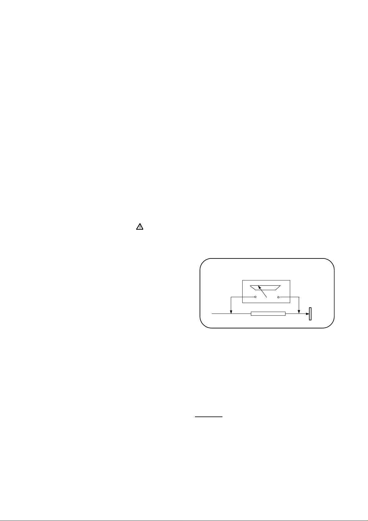
LEAKAGE CURRENT HOT CHECK
1. Plug the AC cord directly in to the AC
outlet. Do not use an isolation transformer
for this check.
2. Connect a 2Kohm 10W resistor in series with
an exposed metallic part on the receiver
and an earth, such as a water pipe.
3. Use an AC voltmeter with high impedance
to measure the potential across the resistor.
4. Check each exposed metallic part and
check the voltage at the each point.
5. Reverse th e AC plug at the outlet and
repeat each of the above measurements.
6. The potential at the any point should not
exceed 1.4 Vrms. In case a measurement is
outside the limits specified, there is the
possibility of a shock hazard, and the
receiver should be repaired and rechecked
before it is returned to the customer.
HOT CHECK CIRCUIT
TO INSTRUMENTS
EXPOSED
METALLIC PARTS
AC-Voltmeter
Water pipe
(earth)
2 K Ohm
Figure 1
X-RAY RADIATION WARNING
The primary source of X-ray radiation in this receiver
is the picture tube. The chassis is specially
constructed to limit X-ray radiation. For continued
X-ray radiation protection, replace the tube with
the same type of the original one.
CAUTION
AFTER REMOVAL OF THE ANODE CAP, DISCHARGE
THE ANODE OF THE PICTURE TUBE AND THE ANODE
CAP TO THE METAL CHASSIS, CRT SHIELD, OR THE
CARBON PAINTED ON THE CRT WITH A HIGH
VOLTAGE PROBE AND MULTIMETER (SELECT VDC)
AND THEN SHORT CIRCUIT DIRECTLY TO DISCHARGE
COMPLETELY.

TECHNICAL SPECIFICATIONS
Power source:
Power consumption (max.)
Standby power consumption
Aerial impedance
Receiving system
PAL SECAM BG
PAL SECAM BG DK
PAL SECAM BG LL’
PAL I
Receiving channels
VHF BAND III CH5-12
CABLE TV S1-41
UHF BAND CH21-69
Audio outputs
High Voltage
Focus voltage
Grid 2 voltage
Heater voltage
Video/Audio Terminals :
Audio : 0.5 Vrms, >10 Kohm
RGB
AV1OUT Video : 1 Vpp, 75 Ohm
Audio : 0.5 Vrms, <1 Kohm
AV2 IN (optional) Video : 1 Vpp,75 Ohm
Audio : 0.5 Vrms, >10 Kohm
AV2 OUT (optional) Video : 1 Vpp, 75 Ohm
Audio : 0.5 Vrms, <1 Kohm
AV2 IN (RCA, optional) Video : 1 Vpp, 75 Ohm
Audio : 0.5 Vrms, >10 Kohm
Operating temperature
Safety
: IEC 65 /BS P2N
X-Ray radiation
1
: TV set is produced to receive “one” of these colour and sound systems.
220-240V AC, 50-60Hz
: 95 W 20”, 21”
: 4 W
: 75Ohm, coaxial type
1
: PAL BG
: VHF BAND I CH2-4
: 2 x 7W RMS at %10 THD
: 25 ± 0.5 KV 20”, 21”
: %25.6 ± %38 of EHT
: 0-1400 V
: 6.2 ± 0.2 Vrms
AV1 IN Video : 1 Vpp,75 Ohm
: 0-45 Degrees
: ACC. IEC 65/BS P2N
CPT
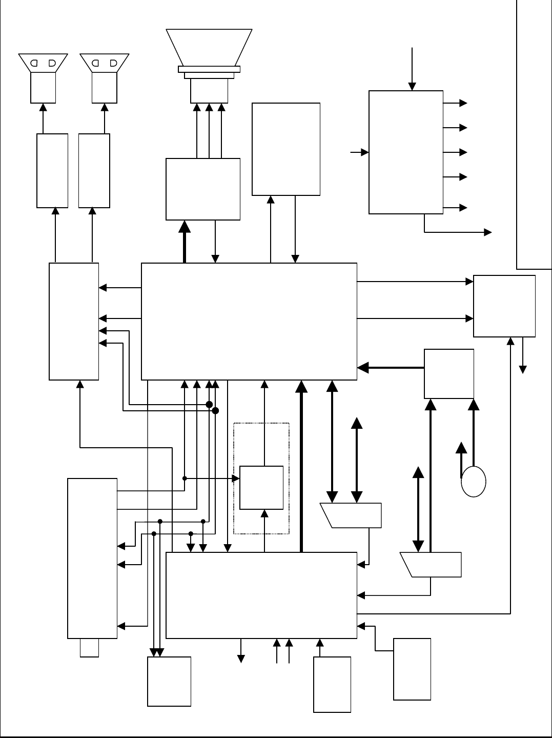
On/off
(Standby)
from IC401
HP
IC317 TDA7480
Audi o Amp.
Left
29
IC316 MSP34X0G
Audio Processor
24
IC318 TDA7480
Right
28
91058 55
HP
8VA
RGB
220V AC in
BU808DFI
Horizontal
Deflection
CRT
Audi o Amp.
IC701
Module
IC901
TDA16847
Power Supply
5VB5VA-13V+13V
U1=114V, 33V
H-Out
H-Sync/LFB
48
49
47
IC101 STV224X
42
SIF
1-2
34-37
22/23
20/13
V-Out
V-Amp
IC501
TDA8174
V-Lin
IC102
Source
Select
12.3 Stereo Block Diagram
.
Deflect
Vertical
Mono in /
Intr/
out
RGB
Aud out
11
QSS
13
8
30-32
6
7-
PIF
I2C 51-52
Black
33
44
V-Sync to IC402
MSP Reset
IC316
IC316Audio
Lum/Chroma
Video In/Out
Audio In/Out IC316
T105,T109
LL’ Switch
8
Scart 1
CVBS-TXT
OSD/TXT RGB out + Fast Blanking
L/L’
43
20
19
33
Tuner
AGC SCL SDA IF1 IF2
53
45
40
41
15-18
Microcontroller
IC 402 ST92195
8
55
147 56
Audio In/Out
CVBS/Chroma
8
SVHS
Scart 2
IR
IC401
EEPROM
On/Off
H-sync
V-sync
(Standby)
To IC901
Keyboard
Receiver
PIN VOLTAGES OF IC'S
IC101 (STV2246)
BUS CONTROLLED MULTISTANDARD ONE CHIP TV PROCESSOR
Pin Connection V DC (*) Pin Connection V DC (*)
1
Sound IF Input 1 1.0
2
Sound IF Input 2 1.0
3
AGC SIF Capacitor 0.1
4
IF Voltage Reference Filtering 3.2
5
AGC PIF Capacitor 0.1
6
Picture IF Input 1 2.5
7
Picture IF Input 2 2.5
8
AGC Tuner Output 4.6
9
IF PLL Filter 1.2
10
IF Ground 0.0
11
AM/FM Mono Sound Output 4.2
12
5 V IF Supply 5.1
13
Internal CVBS Output 3.2
14
External Audio Input 2.5
15
LC Input 1 4.0
16
LC Input 2 4.0
17
Video/Luma Supply Voltage (8 V) 8.1
18
Internal Video Input 3.7
19
Video/Luma Ground 0.0
20
External Video Input 3.2
21
Black Stretch Capacitor 2.8
29
Not connected 3.9
30
Blue Output 2.3
31
Green Output 2.2
32
Red Output 2.3
33
Cathode Current Measurement Input 4.2
34
OSD Blue Input 4.7
35
OSD Green Input 4.8
36
OSD Red Input 4.7
37
OSD Fast Blanking 0.2
38
Cloche Filter Tuning Capacitor 0.1
39
3.5X MHz Crystal 0.4
40
4.43 MHz Crystal -
41
Chroma PLL Filter -
42
Vertical Amplitude DAC Output 4.0
43
Chroma/Scanning Ground 0.0
44
Second Video Switch Output 4.1
45
Chroma/Scanning Power Supply (8V) 8.1
46
Beam Current Limiter Control Voltage and
Safety Input (XRAY)
47
Vertical Output Pulse 4.0
48
Horizontal Output Pulse 1.4
49
Line Flyback Input and Super-sandcastle Output 0.7
6.8
22
Y/CVBSIN3 Y(SVHS) or CVBS3 External Input 3.2
23
Chroma (SVHS) Input 1.8
24
Automatic RGB Peak Regulation 5.0
25
External Blue Input 2.5
26
External Green Input 1.7
27
External Red Input 2.5
28
External Fast Blanking Input 0.0
50
Scanning PLL Filter 4.1
51
SCL I2C Bus Clock Input see osc.
52
SDA I2C Bus Data Input see osc.
53
Digital Supply Voltage (5 V) 5.2
54
Digital Ground 0.0
55
Main Audio Output 4.0
56
FM Demodulation Capacitor 1.5
IC316 (MSP 34XXG)- MULTI STANDARD SOUND PROCESSOR
Pin Connection V DC Pin Connection V DC
1
Not connected 2.3
2
Gnd 0.0
3
Gnd 0.0
4
Digital control input/output 0.0
5
Digital control input/output 0.0
6
Gnd 0.0
7
Standby (in normal operation it must be high) 4.9
8
Not connected 4.9
9
SCL see osc.
10
SDA see osc.
11
Not connected 0.5
12
Not connected 0.5
13
Not connected 0.5
14
Not connected 0.5
15
Not connected 0.5
16
Not connected 0.5
17
ADR Bus Clock Output 0.5
18
Digital Circuitry Supply Voltage 4.9
19
Digital Circuitry Supply Ground 0.0
20
Not connected 0.5
21
Not connected (Ground) 0.0
22
Not connected (Ground) 0.0
23
Not connected (Ground) 0.0
24
MSP RESET input 5.1
25
Headphone sound output (R) 0.1
26
Headphone sound output (L) 0.1
27
Reference analog ground 0.0
28
Speaker output (R) 0.1-2.1
29
Speaker output (L) 0.1-2.1
30
Not connected 0.1-2.1
31
Not connected 0.1-2.1
32
Not connected 0.1-2.1
33
Scart 2 sound output (R) 3.7
34
Scart 2 sound output (L) 3.7
35
Reference analog ground 0.0
36
Scart 1 sound output (R) 3.7
37
Scart 1 sound output (L) 3.7
38
Volume capacitor Headphone 7.1
39
Analog Supply High Voltage (8V) 8.0
40
Volume capacitor Speaker 7.1
41
Ground for Analog Power Supply High Voltage 0.0
42
Internal Analog Reference Voltage 3.7
43
Scart 4 input (L) 3.7
44
Scart 4 input (R) 3.7
45
Analog Shield Ground 0.0
46
CINCH - sound input (L) 3.7
47
CINCH - sound input (R) 3.7
48
Analog Shield Ground 0.0
49
Scart 2 sound input (L) 3.7
50
Scart 2 sound input (R) 3.7
51
Analog Shield Ground 0.0
52
Scart sound 1 input (R) 3.7
53
Scart 1 sound input (L) 3.7
54
A/D converter ref. Voltage 2.5
55
Mono sound input 3.7
56
Ground for Analog Power Supply Voltage 0.0
57
Analog Power Supply Voltage (5V) 4.9
58
IF input 1 1.5
59
IF Common reference for IF IN1/IN2 1.5
60
IF input 2 0.0
61
Factory test mode enable (ground) 0.0
62
Crystal oss. input 2.3
63
Crystal oss. output 2.3
64
Not connected (Ground) 0.0
IC317, IC318 (TDA7480) Audio Output IC
Pin Connection V DC Pin Connection V DC
1
Negative supply (-13V) -13.5
2
Negative supply (-13V) -13.5
3
Negative supply (-13V) -13.5
4
Output (Pulse width modulated) 0.0
5
Built-in Bootstrap diode anode -2.6
6
Built-in Bootstrap capacitor 10.0
7
Not connected 0.0
8
Feedback integrating capacitance 0.0
9
Setting frequency resistor -11.6
10
Signal ground 0.0
11
Input 0.0
12
Standby / mute control pin 5.1 (0.4)
13
Not connected 0.0
14
Positive signal supply 13.0
15
10V internal regulator -2.6
16
Positive power supply (+13V) 13.0
17
Negative supply (-13V) -13.5
18
Negative supply (-13V) -13.5
19
Negative supply (-13V) -13.5
20
Negative supply (-13V) -13.5
 Loading...