

Configuration and installation guide
Copyright © All rights reserved. Patent pending.

Before you start
Dear reader,
We recommend that you read and follow this step-by-step guide to configuration and installation of the
BEKEY door unit. The guide includes:
1. Product specification
2. Configuration of the door unit
3. Installation on the door*
In order to ensure correct functionality of the product it is very important that the above steps are followed
as described in this document.
Best regards,
BEKEY
*This installation guide pertains to the lock type ”Regular deadbolt”. If you have purchased an add-on package
with your BEKEY door unit, by step 3, follow the instructions from the package to complete the installation on your
lock. Should you have any questions, please contact BEKEY support through our website www.bekey.dk/support.
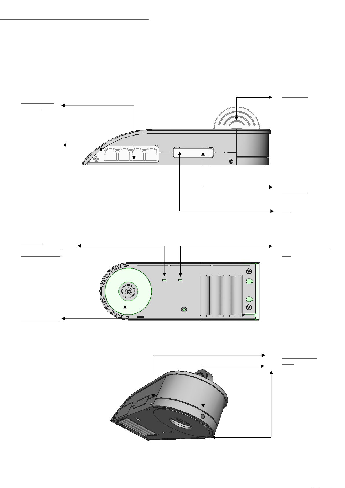
4 x 1.5V AA
Batteries
Battery cover
Switch for
clockwise/counterclockwise opening
Attachment plate
Thumb turn
Enables manual
opening.
Lock button
Press to unlock/lock.
LED
BLUE = Lock is active
RED = Batteries need
replacement
Switch for latch/bolt
lock
.
Three hex screw
holes
Fastens the door unit
to the installation
plate.
1. Product specification

2. Configuration of the door unit
In order to configure your door unit, you need to choose the correct settings for the unit.
Position the unit as shown below.
If your door has a latch lock, you simpkly close the door in order to lock it –
without the need for a key. If your door has a bolt lock, you need a key in
order to lock the door.
Position the top switch according to your lock type:
Latch lock = switch up
Bolt lock = switch down
Next you need to set the lock direction, i.e. does the key turn clockwise or
counter-clockwise when unlocking. Look at your door from the outside and
determine if the key turns clockwise or counter-clockwise.
If the key is turned counter-clockwise when unlocking, you need to set the
bottom switch to “Left”.
If the key is turned clockwise when unlocking, you need to set the bottom
switch to ”Right”.
Counter-clockwise = Left (switch up)
Clockwise = Right (switch down)
Remember that the direction is determined by observing the door from the outside!

3. Installation on the door
Remember – in case you have purchased an add-on package with your BEKEY door unit, you must follow the
installation guide enclosed in the package.
Enclosed in the package is a tool set. Your lock type may require certain screw bits that are not enclosed in
the package. Should this be the case, we recommend that you take a picture of the bits and contact your
local tool store.
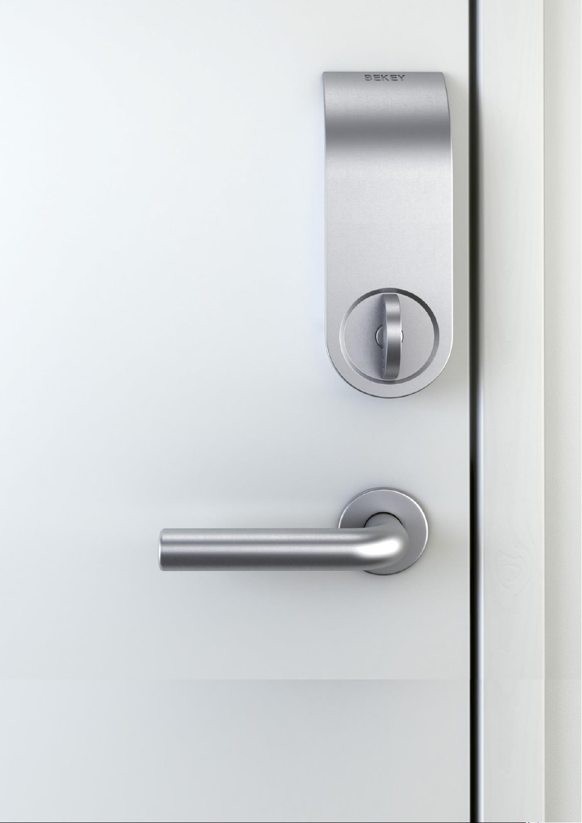
Placement of the door unit
Check that the size of the door unit does not affect the functionality of the door or the existing lock.
The door unit can be installed in three different ways, as shown below, depending on the position of the
door handle:

+
The door unit.
Attachment plate as it is
placed on the door.
Installation overview
1) If the lock is a bolt lock, place the bolt in the unlocked position, A. Place the thumb turn, B, vertically.
2) Make sure that the key is not sitting in the outside keyhole, C.
3) Place the installation screws, D, in the two holes on the back of the attachment plate, E, and place the
spindle, F, through the center of the attachment plate. Adjust the two holes in the cylinder, C, and
fasten the attachment plate.
4) Place the door unit over the attachment plate on the door G/E and fasten the three hex screws in the
bottom of the door unit, H, (illustration below).

Step-by-step installation
Step 1
Step 2
Step 3
When the door unit is attached to the attachment plate, tighten the three screws at the bottom of the unit. This
ensures that the door unit is fastened to the attachment plate.
Remove the two screws, A and B, from the
existing thumb turn. The number of screws
depends on the lock type. Most locks have
two screws.
Replace the thumb turn with the attachment plate
from the package. Place the plate with the flat
side against the door. Reuse the two screws, A
and B, and fasten the plate on the door.
1
2 3 4
A. The plate is fastened to the door,
and the spindle sits in the center of
the plate. The distance between the
door and the tip of the spindle must
not exceed 25 mm in length.
B. Place the door unit over the
attachment plate. Adjust the center
to fit the spindle.
If the existing spindle is too short, or
of a different type than shown here,
please use the spindle and plate
from the package.

Step 4
Remove the battery cover Insert 4 AA-batteries
Step 5
Test the functionality of the door unit by pressing the lock button, D, and then manually turn the thumb button, B, on the unit.
Step 6
Test whether the key, E, on the outside of the door works properly, locking and unlocking the door easily.

BEKEY A/S Bredebjergvej 6 DK-2630 Taastrup +45 4343 9990 www.bekey.dk
4. FCC
This device complies with Part 15 of the FCC Rules. Operation is subject to the following two conditions:
(1) this device may not cause harmful interference, and
(2) this device must accept any interference received, including interference that may cause undesired
operation.
No changes shall be made to the equipment without the manufacturer’s permission as this may void the
user’s authority to operate the equipment.
The Bekey as ML1-1 has been designed and complies with the safety requirements for portable (<20cm) RFexposure in accordance with FCC rule part §2.1093 and KDB 447498 D01.
 Loading...