

Page 1
Instruction sheet for BR385
Intrinsically safe Sounder
BR385 sounders are CE marked to show
compliance with the European Explosive
Atmospheres Directive 2014/34/EU and the
European EMC Directive 2014/30/EU
1. INTRODUCTION
The BR385 is a third generation ATEX, IECEx and FM certified
intrinsically safe sounder that produces a loud warning signal in a
hazardous area. Forty nine different first stage alarm sounds can be
selected by internal switches and each one can be externally changed to
a second or third stage alarm sound. For ATEX and IECEx installations
the sounder can be used in all gas groups and may be powered from a
BA386 LED flashing beacon, allowing a combined audible and visual
alarm to be constructed.
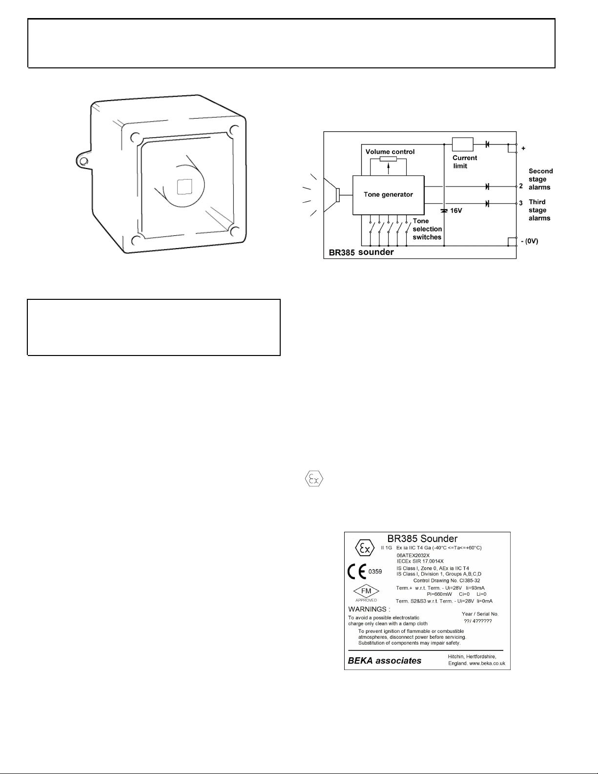
Fig 1 Simplified block diagram
4. ATEX INTRINSIC SAFETY CERTIFICATION
4.1 ATEX certificate
The BR385 sounder has been issued with an EU-Type Examination
Certificate 06ATEX2032X. This has been used to confirm compliance
with the European ATEX Directive 2014/34/EU for Group II, Category 1G
equipment. See product Declaration of Conformity for confirmation of
compliance with current harmonised standards.
The sounder carries the Community Mark and subject to local codes of
practice, may be installed in any of the EEA member countries. This
instruction sheet describes installations which conform to EN 60079-14
Electrical installations design, selection and erection. When designing
systems for installation outside the UK, the local Code of Practice should
be consulted.
2. DESCRIPTION
Fig 1 shows a simplified block diagram of a BR385 sounder. The device
operates immediately power is applied to the + and - terminals which are
duplicated to allow a second sounder to be connected in parallel, or for an
end of line monitoring resistor to be installed. The output tone is defined
by the position of the six internal switches and this tone can be changed to
a second or third stage alarm tone by connecting terminals S2 or S3 to the
– terminal of the sounder. The tone generator is crystal controlled to
ensure that when two sounders are started at the same time their output
tones remain synchronised.
3. SUPPLY VOLTAGE
For hazardous area installations, BR385 sounders must be powered from
a certified Zener barrier or galvanic isolator that will supply between 8 and
28V at the + and – terminals of the sounder.
Sounders may be tested or used in safe areas without a Zener barrier or
galvanic isolator, but at supply voltages above 16V the internal current
limit will function and the audio output will be reduced. Direct connection
to supplies up to 28V of either polarity will not damage the sounder, but it
is recommended that sounders are not operated continuously with a direct
supply greater than 16V.
II 1G Ex ia IIC T4 Ga (-40ºC <= Ta <= +60ºC)
Typical BR385 certification information label
Layout and content may vary
Page 2

2
The EU-Type Examination Certificate has an 'X' suffix indicating that the
following special conditions for safe use apply. Practical implications are
explained in later sections of this instruction sheet.
SPECIAL CONDITIONS FOR SAFE USE
The equipment has an ingress protection rating of IP66. However,
if it has been supplied without cable entry devices, then the user
shall ensure that the devices that are fitted will provide an ingress
protection that is appropriate to the environment in which it is
installed i.e. IP20 or better.
The total capacitance connected to terminals + wrt - (i.e. the
capacitance of the cable plus any other capacitance) shall not
exceed 83nF.
The equipment shall not be directly installed in any process where
its enclosure might be electro-statically charged by the rapid flow
of a non-conductive media.
The equipment shall only be supplied via Terminals + w.r.t.
Terminals - from a barrier having a maximum open circuit voltage
Uo that is <
93mA, where Io is resistively limited. The barrier or galvanic
<
isolator shall be ATEX certified by a notified body.
4.2 Zones, Gas Groups and T rating
The BR385 sounder has been certified Ex ia IIC T4 Ga. When
connected to approved Zener barriers or galvanic isolators it may be
installed in:
Zone 0 explosive gas air mixture continuously present.
Zone 1 explosive gas air mixture likely to occur in normal
Zone 2 explosive gas air mixture not likely to occur, and if it
Warning Do not install the BR385 where it may accumulate
Be used with gases in groups:
Group A propane
Group B ethylene
28V and a maximum short circuit current Io that is
operation.
does, it will only exist for a short time.
an electrostatic charge from a rapid flow of dry air.
4.3 Terminals + and -
Power is supplied to the sounder via terminals + & - which have the
following maximum input safety parameters:
Ui = 28V
Ii = 93mA dc
Pi = 0.66W
BR385 sounders may be powered from any ATEX Ex ia IIC certified Zener
barrier or galvanic isolator having output parameters equal to, or less
than, these limits. e.g. a certified 28V, 93mA, 0.66W Zener barrier or
isolator may be used.
The BR385 ATEX certificate specifies that the maximum permitted total
capacitance that may be connected between the + and - terminals shall
not exceed 83nF, irrespective of the Zener barrier or galvanic isolator
powering the sounder. This total capacitance includes the cable
capacitance plus the capacitance of any other connected device. This
should not be restrictive unless the sounder and the barrier or isolator are
a long way apart. Single pair instrumentation cables have a typical
capacitance of 100pF/metre rising to 350pF/metre for multicore cables
and are unlikely to exceed 600pF/metre allowing a cable length of up to
830, 230 or 138 metres respectively.
Up to three BR385 sounders may be connected in parallel and powered
from a common barrier or isolator providing the voltage between the + and
– terminals does not fall below 8V. Connecting two sounders in parallel
will reduce the output from each sounder by about 3dB. Three sounders
should only be powered from a common supply when the maximum
supply voltage is available.
4.4 Terminals S2 and S3
When terminals S2 or S3 are connected to 0V ( - terminal) the sounder
output tone changes to the second or third stage alarm respectively. The
input safety parameters for these terminals are:
Ui = 28V
Ii = 0mA
Therefore for control from the safe area terminals S2 & S3 may only be
connected to a certified diode return barrier, or the contacts of a certified
intrinsically safe relay. For functional reasons diode return barriers with a
voltage drop of less than 0.9V must be used. The maximum permitted
cable capacitance Co will be specified on the diode return barrier ATEX
certificate, but again should not be restrictive.
For control from the hazardous area terminals S2 & S3 may be directly
connected to a mechanically operated switch in the hazardous area
complying with the requirements for simple apparatus as defined in
EN 60079-11. i.e. having IP20 protection and able to withstand a 500V
rms insulation test to earth for one minute.
Group C hydrogen
Having a temperature classification of:
T1 450ºC
T2 300ºC
T3 200ºC
T4 135ºC
5. INSTALLATION
BR385 sounders should only be installed by trained competent personnel.
5.1 Mounting
The BR385 sounder may be secured to any flat surface using the two
7mm diameter fixing holes. The enclosure provides IP66 protection and is
suitable for installation in sheltered exterior locations providing it is
positioned so that water can not collect in the horn, and the cable entry is
sealed.
Page 3
3
5.2 Installation procedure
a. Secure the BR385 sounder to a flat surface via the two 7mm dia
fixing holes in the mounting feet.
b. Remove the front of the sounder by unscrewing the four captive
corner screws and pulling the front away from the enclosure.
c. Fit an appropriate 20mm cable gland or conduit entry into the
untapped hole in the enclosure and connect the field wiring to the
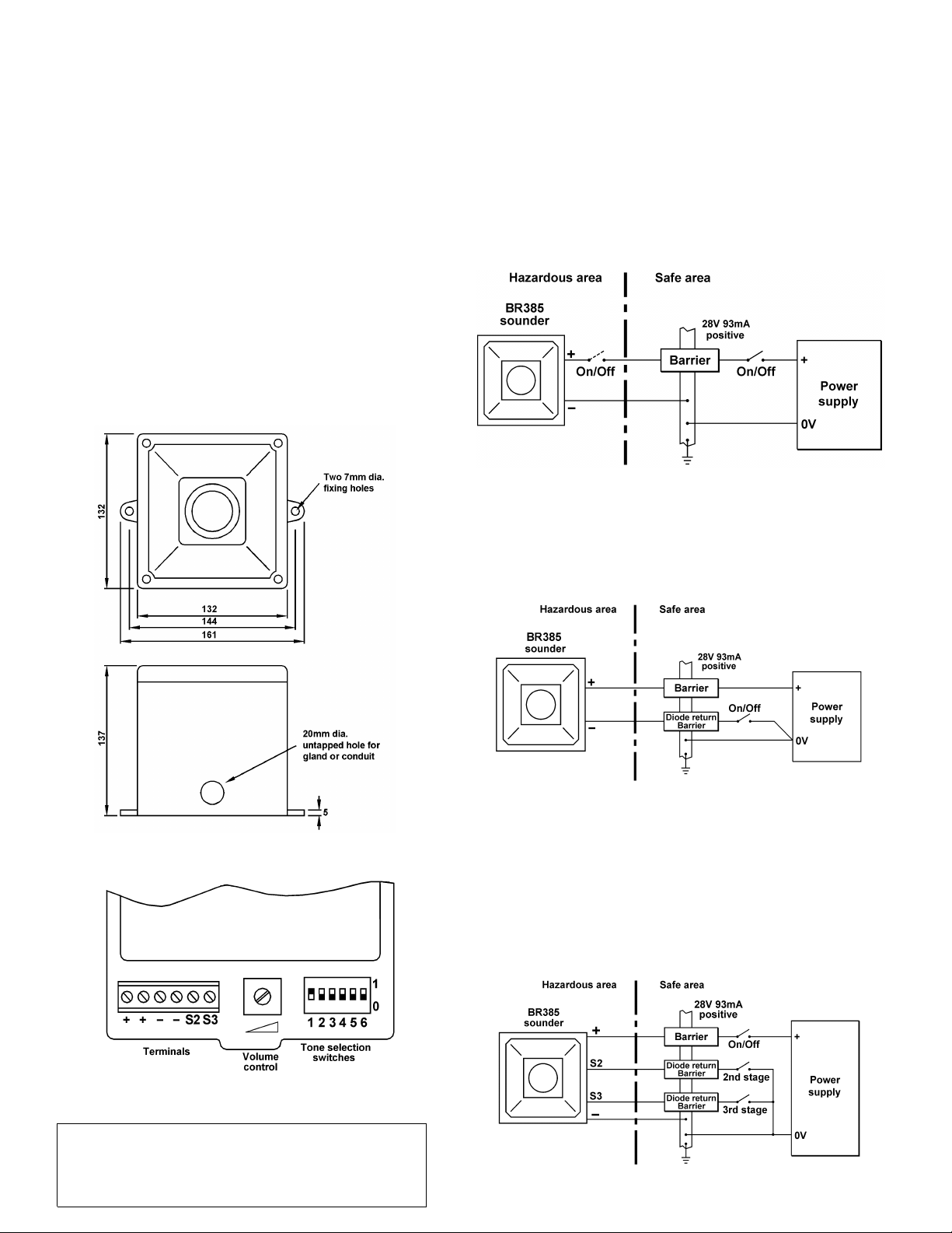
appropriate sounder terminals as shown in Fig 3. The power
supply terminals + and – are duplicated so that sounders may be
connected in parallel, or an end-of-line monitoring resistor may
be fitted.
d. Select the required output tone by positioning the six switches as
shown in Table 1 and Fig 3.
e. Apply power to the sounder and adjust the internal volume
control to provide the required sound level.
f. Replace the front of the sounder and tighten the four corner
screws.
6. ELECTRICAL SYSTEM DESIGN FOR INSTALLATION IN
HAZARDOUS AREAS USING ZENER BARRIERS
6.1 Single stage alarm
If the control switch is in the positive supply, or the power supply is being
turned on and off, only a single channel Zener barrier is required as
shown in Fig 4. This circuit may also be used if the sounder is being
controlled from the hazardous area by a mechanically activated switch
complying with the requirements for simple apparatus. as defined by
EN 60079-11. i.e. having IP20 protection and able to withstand a 500V
rms insulation test to earth for one minute.
Fig 4 Single stage alarm using single channel barrier.
Fig 2 Enclosure
If the negative side or the power supply and one side of the control switch
are earthed, the circuit shown in Fig 5 may be used.
Fig 5 Single stage alarm using two channel barrier.
6.2 Multi-stage alarm
Connecting terminal S2 to 0V activates the second stage alarm, and
similarly terminal 3 for the third stage alarm. Fig 6 shows how diode return
barrier(s) may be used to control the sounder from the safe area. If only
two stages of alarm are required the third stage barrier should be omitted,
the 28V 93mA barrier and the single diode return channel may then be
contained in one package.
Fig 3 Location of field terminals and controls.
WARNING
To avoid a possible electrostatic charge
only clean BR385 sounder with a damp cloth.
Fig 6 Multi-stage alarm using Zener barriers.
Page 4
4
7. ELECTRICAL SYSTEM DESIGN FOR INSTALLATION IN
HAZARDOUS AREAS USING GALVANIC ISOLATORS.
Galvanic isolators although more expensive than Zener barriers, do not
require a high integrity earth connection. For small systems where a high
integrity earth is not already available, the use of galvanic isolators often
reduces the overall installation cost and simplifies design.
7.1 Single stage alarm
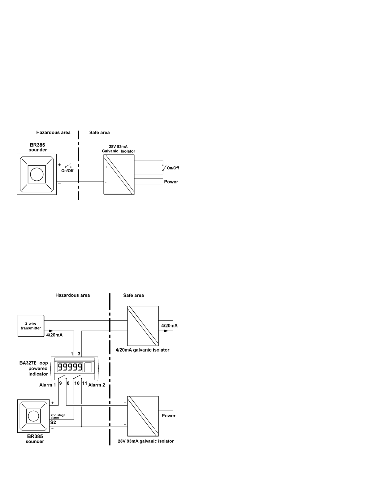
BR385 sounders may be powered by any Ex ia ATEX certified galvanic
isolator having output parameters within the limits specified in section 4.3.
The sounder may be controlled by turning the galvanic isolator on and off,
or from the hazardous area by a mechanically activated switch complying
with the requirements for simple apparatus as defined by EN 60079-11.
i.e. having IP20 protection and able to withstand a 500V rms insulation
test to earth for one minute.
8. ACCESSORIES
8.1 Tag number
BR385 sounders can be supplied identified by a tag number thermally
printed on a self adhesive label.
9. SERVICING
No attempt should be made to repair a faulty BR385 sounder. Suspect
sounders should be returned to BEKA associates or our local agent for
repair.
10. GUARANTEE
Sounders which fail within the guarantee period should be returned to
BEKA associates or our local agent. It is helpful if a brief description of
the fault symptoms is provided.
11. CUSTOMER COMMENTS
BEKA associates is always pleased to receive comments from customers
about our products and services. All communications are acknowledged
and whenever possible, suggestions are implemented.
Fig 7 Single stage alarm using galvanic isolator
.
7.2 Multi-stage alarm
Fig 8 shows a typical application in which the first and second stage alarm
tones are activated by the alarm outputs of a BA327E intrinsically safe
loop powered indicator. The BA327E alarm outputs have been certified as
simple apparatus and may therefore be used to switch the BR385 sounder
in the hazardous area. The contacts of most certified intrinsically safe
relays may also be used in the same way.
Fig 8 Loop-powered BA327E intrinsically safe indicator
activating BR385 first and second stage alarms
Page 5

5
Tone
Number
Tone 1
Tone 2
Tone 3
Tone 4
Tone 5
Tone 6
Tone 7
Tone 8
Tone 9
Tone 10
Tone 11
Tone 12
Tone 13
Tone 14
Tone 15
Tone 16
Tone 17
Tone 18
Tone 19
Tone 20
Tone 21
Tone 22
Tone 23
Tone 24
Tone 25
Tone 26
Tone 27
Tone 28
Tone 29
Tone 30
Tone 31
Tone 32
Tone 33
Tone 34
Tone 35
Tone 36
Tone 37
Tone 38
Tone 39
Tone 40
Tone 41
Tone 42
Tone 43
Tone 44
Tone 45
Tone 46
Tone 47
Tone 48
Tone 49
Continuous 340Hz
Alternating 800/1000Hz @ 0.25s intervals
Slow whoop 500/1200Hz @ 0.3Hz with 0.5s gap repeated
Sweeping 500/1000Hz @ 1Hz
Continuous 2400Hz
Sweeping 2400/2900Hz @ 7Hz
Sweeping 2400/2900Hz @ 1Hz
Siren 500/1200/500Hz @ 0.3Hz
Sawtooth 1200/500Hz @ 1Hz - D.I.N.
Alternating 2400/2900Hz @ 2Hz
Intermittent 1000Hz @ 1Hz
Alternating 800/1000Hz @ 0.875Hz
Intermittent 2400Hz @ 1Hz
Intermittent 800Hz 0.25s ON, 1s OFF
Continuous 800Hz
Intermittent 660Hz 150Ns ON, 150ms OFF
Alternating 544Hz (100ms) / 440Hz (400ms) – NFS 32-001
Intermittent 660Hz 1.8s ON, 1.8s OFF
Sweep 1400Hz to1600Hz up 1s 1600Hz to 1400Hz down 0.5s
Continuous 660Hz
Alternating 554/440Hz @ 1Hz
Intermittent 544Hz @ 0.875Hz
Intermittent 800Hz @ 2Hz
Sweeping 800/1000Hz @ 50Hz
Sweeping 2400/2900Hz @ 50Hz
Simulated bell
Continuous 554Hz
Continuous 440Hz
Sweeping 800/1000Hz @ 7Hz
Continuous 300Hz
Sweeping 660/1200 @ 1Hz
Two Tone Chime
Intermittent 745Hz
Alternating 1000/2000Hz @ 0.5s – Singapore
420Hz @ 0.625s - Australian Alert
500-1200Hz 3.75s / 0.25s - Australian Evacuate
Continuous 1000Hz
Continuous 2000Hz
Intermittent 800Hz 0.25s ON 1s OFF
Alternating 544Hz (100ms) / 440Hz (400ms) – NFS 32-001
Motor Siren – Slow rise to 1200Hz
Motor Siren – Slow rise to 800Hz
Continuous 1200Hz
Motor Siren – Slow rise to 2400Hz
Intermittent 1000Hz 1s ON, 1s OFF
Sawtooth 1200/500Hz @ 1Hz - D.I.N. (PFEER P.T.A.P)
Intermittent 1000Hz 1s ON, 1s OFF – PFEER General Alarm
420Hz @ 0.625s - Australian Alert
500-1200Hz 3.75s / 0.25s - Australian Evacuate
Switch
Settings
1 2 3 4 5 6
0 0 0 0 0 0
1 0 0 0 0 0
0 1 0 0 0 0
1 1 0 0 0 0
0 0 1 0 0 0
1 0 1 0 0 0
0 1 1 0 0 0
1 1 1 0 0 0
0 0 0 1 0 0
1 0 0 1 0 0
0 1 0 1 0 0
1 1 0 1 0 0
0 0 1 1 0 0
1 0 1 1 0 0
0 1 1 1 0 0
1 1 1 1 0 0
0 0 0 0 1 0
1 0 0 0 1 0
0 1 0 0 1 0
1 1 0 0 1 0
0 0 1 0 1 0
1 0 1 0 1 0
0 1 1 0 1 0
1 1 1 0 1 0
0 0 0 1 1 0
1 0 0 1 1 0
0 1 0 1 1 0
1 1 0 1 1 0
0 0 1 1 1 0
1 0 1 1 1 0
0 1 1 1 1 0
1 1 1 1 1 0
0 0 0 0 0 1
1 0 0 0 0 1
0 1 0 0 0 1
1 1 0 0 0 1
0 0 1 0 0 1
1 0 1 0 0 1
0 1 1 0 0 1
1 1 1 0 0 1
0 0 0 1 0 1
1 0 0 1 0 1
0 1 0 1 0 1
1 1 0 1 0 1
0 0 1 1 0 1
1 0 1 1 0 1
0 1 1 1 0 1
1 1 1 1 0 1
0 0 0 0 1 1
Second
Stage
Alarm
Tone 2
Tone 17
Tone 2
Tone 6
Tone 3
Tone 7
Tone 10
Tone 2
Tone 15
Tone 7
Tone 2
Tone 4
Tone 15
Tone 4
Tone 2
Tone 18
Tone 2
Tone 2
Tone 2
Tone 2
Tone 2
Tone 2
Tone 6
Tone 29
Tone 29
Tone 2
Tone 26
Tone 2
Tone 7
Tone 2
Tone 26
Tone 26
Tone 2
Tone 38
Tone 36
Tone 35
Tone 9
Tone 34
Tone 23
Tone 31
Tone 2
Tone 2
Tone 2
Tone 2
Tone 38
Tone 47
Tone 46
Tone 49
Tone 26
Third
Stage
alarm
Tone 5
Tone 5
Tone 5
Tone 5
Tone 20
Tone 5
Tone 5
Tone 5
Tone 2
Tone 5
Tone 5
Tone 5
Tone 5
Tone 5
Tone 5
Tone 5
Tone 27
Tone 5
Tone 5
Tone 5
Tone 5
Tone 5
Tone 5
Tone 5
Tone 5
Tone 15
Tone 5
Tone 5
Tone 5
Tone 5
Tone 5
Tone 15
Tone 5
Tone 45
Tone 5
Tone 5
Tone 45
Tone 45
Tone 17
Tone 27
Tone 5
Tone 5
Tone 5
Tone 5
Tone 34
Tone 37
Tone 37
Tone 5
Tone 37
Table 1 Function of tone selection switches
Page 6

6
APPENDIX 1
Installation in USA
A1.0 Factory Mutual Certification
For installations in the USA the BR385 sounder has the following FM
intrinsic safety certification;
CLI; Div 1; Gp A, B, C & D T4 Ta = 60°C Entity IP66
CLI; Zone 0; AEx ia IIC T4 Ta = 60°C Entity IP66
The FM Certificate of Compliance 3027157 and the associated BEKA
Control Drawing CI385-32 may be downloaded from www.beka.co.uk, or
requested from the BEKA sales office or our US agent Exloc Instruments.
A1.1 Divisions / Zones, Gas Groups and T rating
The BR385 sounder has been approved intrinsically safe by FM for
installation in the following Divisions / Zones and used with the following
hazards.
Installation in:
Division 1 Ignitable concentrations of flammable
gases, vapours or liquids can exist all of the
time or some of the time under normal
operating conditions.
Division 2 Ignitable concentrations of flammable
gases, vapours or liquids are not likely to
exist under normal operating conditions.
Zone 0 Explosive gas air mixture continuously
present.
A1.2 Intrinsic safety parameters
The BR385 sounder has been assessed using the entity concept and the
FM safety parameters are identical to the ATEX and IECEx safety
parameters except that output parameters Uo, Io and Po are specified for
the two tone changing terminals S2 and S3. Uo limits the maximum
cable capacitance to 390nF in gas group B and IIC (hydrogen) when the
terminals are connected to an isolated contact. This is unlikely to be
restrictive. Uo is unlikely to reduce the permitted cable capacitance when
the terminals are connected to a diode return barrier or galvanic isolator in
the safe area, but Io should be considered when determining the
maximum permitted cable inductance, but again is unlikely to be
restrictive.
APPENDIX 2
IECEx certification
A2.0 The IECEx Certification Scheme
IECEx is a global certification scheme for explosion protected products
which aims to harmonise international certification standards. For
additional information about the IECEx certification scheme and to view
the BEKA associate certificates, please visit www.iecex.com
A2.1 IECEx Certificate of Conformity
The BR385 sounder has been issued with an IECEx Certificate of
Conformity number IECEx SIR 17.0014X which specifying the following
certification code:
Ex ia IIC T4 Ga -40ºC ≤ Ta ≤ +60ºC.
Zone 1 Explosive gas air mixture likely to occur in
normal operation.
Zone 2 Explosive gas air mixture not likely to occur,
and if it does, it will only exist for a short
time.
Use with gases in groups:
Group A Acetylene
Group B Hydrogen
Group C Ethylene
Group D Propane
IIA Propane
IIB Ethylene
IIC Hydrogen
Having a temperature classification of:
T1 450ºC
T2 300ºC
T3 200ºC
T4 135ºC
at an ambient temperature between -20ºC and +60ºC
The IECEx certificate may be downloaded from www.beka.co.uk,
www.iecex.com or requested from the BEKA sales office.
A2.2 Installation
The IECEx intrinsic safety parameters are identical to the ATEX safety
parameters described in the main section of this manual and both refer to
the same standards. Therefore the ATEX installation requirements
specified in this manual also apply for IECEx installations, but the local
code of practice should also be consulted.
A2.3 Special conditions for safe use
The IECEx certificate has an ‘X’ suffix indicating that special conditions
apply to prevent an electrostatic charge developing on the outside of the
instrument enclosure - see section 4.1.
To avoid an electrostatic charge being generated BR385
enclosure should only be cleaned with a damp cloth.
To avoid a possible electrostatic charge
WARNING
WARNING
only clean BR385 sounder with a damp cloth.
BEKA associates Ltd
Old Charlton Road
Hitchin
Herts
SG5 2DA
UK
Telephone +44 (0)1462 438301 Fax +44 (0)1462 453971 e-mail [email protected] www.beka.co.uk
Issue 9 September2019
 Loading...