

Page 1
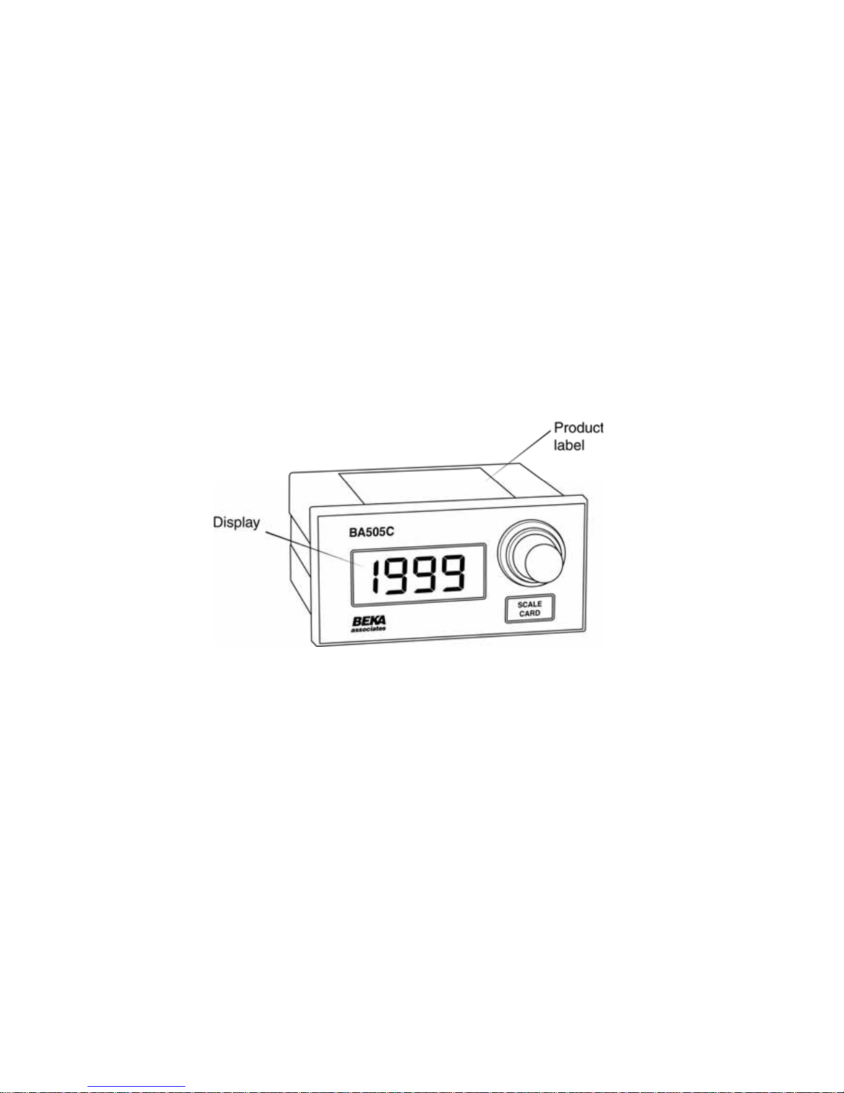
BA505C
2-wire 4/20mA
manual setpoint
station
Issue 6
Issue: 6
3
rd
December 2010
Page 2

2
1. Description
2. Operation
3. Electrical Systems Design
3.1 4/20mA loop
3.2 Optional Backlights
3.2.1 Separately powered
3.2.2 Loop powered
4. Installation
4.1 Location
4.2 Installation procedure
4.3 EMC
5. Calibration
5.1 Internal display
5.2 Zero adjustment
5.3 Span adjustment
5.4 Decimal point
5.5 Reverse action
5.6 Calibration example
5.7 Over and under-range
6. Maintenance
6.1 Fault finding during commissioning
6.2 Fault finding after commissioning
6.3 Servicing
6.4 Guarantee
6.5 Customer comments
7. Accessories
7.1 Scale card.
7.2 Tag strip
CONTENTS
The BA505C is CE marked to show compliance with the European EMC Directive 2004/108/EC
Page 3
3
1. Description
The BA505C is a loop powered set point station
which enables the current flowing in a 4/20mA
loop to be manually adjusted from within a
process area.
The main application of the BA505C is the
adjustment of plant parameters. Controller set
points, actuator positions or any parameter
controlled by a 4/20mA signal may be manually
adjusted by a BA505C.
The BA505C incorporates a high resolution ten
turn potentiometer to provide accurate adjustment
and is fitted with a friction damper to minimise the
possibility of accidental adjustment. The
instrument incorporates a 3½ digit indicator which
may be calibrated to display the 4/20mA loop
current in engineering units. Optional display
backlighting is available for installations in poorly
illuminated areas.
The BA505C is a second generation instrument
offering improved performance and an IP65
sealed front panel. For hazardous area
applications the complementary BA405C has
been certified intrinsically safe by Baseefa and
FM.
2. Operation
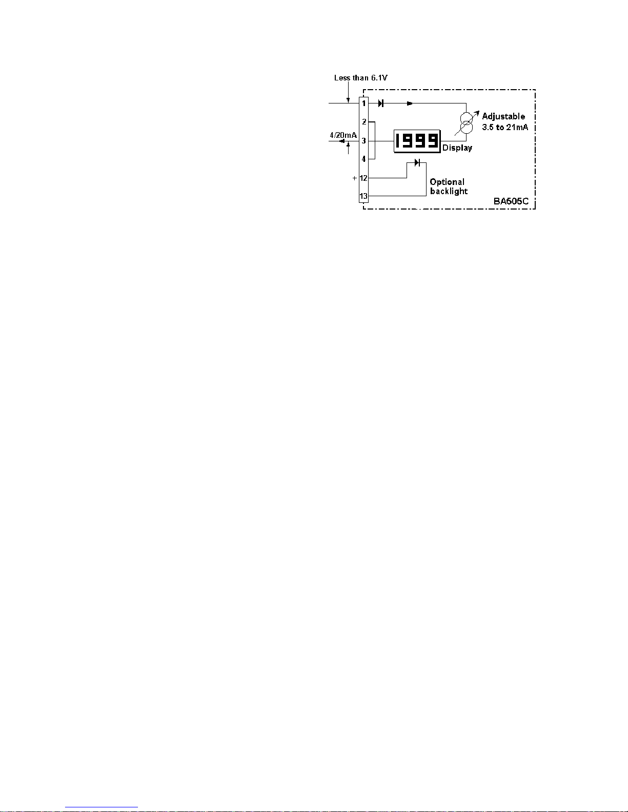
Fig 1 shows a simplified block diagram of the
manual set point station. The ten turn control
knob enables the current flowing in the loop to be
manually set at any value between approximately
3.5 and 21mA. The output resistance of the
BA505C is very high so the loop current will be
unaffected by changes in supply voltage.
The 3½ digit integral indicator is powered by the
4/20mA loop current and can easily be calibrated
on-site. For example, in an application where the
BA505C is being used to adjust the set point of a
speed controller, the internal indicator could be
calibrated to display the required speed in
RPM.
Optional display backlighting is powered from a
separate supply.
Fig 1 Simplified block diagram of BA505C
3. Electrical System Design
3.1 4/20mA loop
The BA505C requires an operating voltage
between 6.1 and 30V. Design of the loop is
similar to that for a 2-wire temperature or pressure
transmitter.
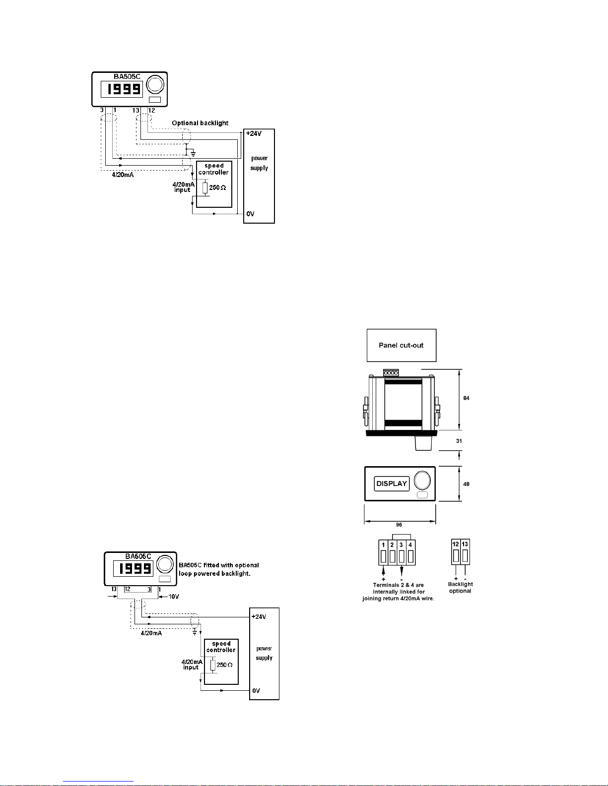
Fig 2 illustrates a typical application in which a
BA505C is powered from a common supply.
When designing the loop it is only necessary to
establish that the maximum voltage drop caused
by the manual set point station, the load and cable
resistance is always less than the minimum supply
voltage.
For example:
Minimum operating voltage of BA505C 6.1V
Maximum voltage drop caused by
speed controller which is a 250ohm 5.0V
load (250ohms x 20mA)
Maximum voltage drop caused by cable 0.2V
resistance (10ohms x 20mA)
--------Total maximum voltage drop 11.3V
The power supply voltage must therefore be
greater than 11.3V, but less than 30V which is the
maximum operating voltage of the BA505C.
Page 4
4
Fig 2 Application with separately powered
backlight.
3.2 Optional Backlights
The BA505C can be supplied with a separately
powered or a loop powered backlight. The
separately powered backlight provides bright
amber illumination but requires additional field
wiring. The loop powered backlight provides
green background illumination enabling the
display to be read at night or in poorly illuminated
areas, but increases the BA505C minimum
operating voltage to 10V.
3.2.1 Separately powered backlight
The backlight is electrically isolated from the
measuring circuit and may be powered from any
14 to 30V dc supply as shown in Fig 2. The
backlight brilliance may be reduced by reducing
the supply voltage below 14V, or by fitting a
current limiting resistor in series with the supply.
3.2.2 Loop powered backlight
The loop powered backlight is connected in series
with, and powered by, the 4/20mA current from
the set point station as shown in Fig 2A. This
eliminates the need for additional field wiring, but
the minimum operating voltage of the set point
station is increased from 6.1 to 10.0V.
Fig 2A Application with loop powered backlight
4. Installation
4.1 Location
The BA505C is housed in a robust aluminium
enclosure with a polyester front panel and a Noryl
bezel. The front panel provides IP65 protection
and a gasket seals the joint between the
instrument and the front panel. The BA505C
may be installed in any panel providing the
environmental limits shown in the specification are
not exceeded.
Fig 3 shows the enclosure dimensions and the
recommended panel cut-out dimensions.
Cut-out Dimensions
DIN 43 700
92.0 +0.8/-0.0 x 45.0 _0.6/-0.0
To achieve an IP65 seal between
BA505C and instrument panel
90.0 +0.5/-0.0 x 43.3 +0.5/0.0
Fig 3 BA505C dimensions
4.2 Installation Procedure
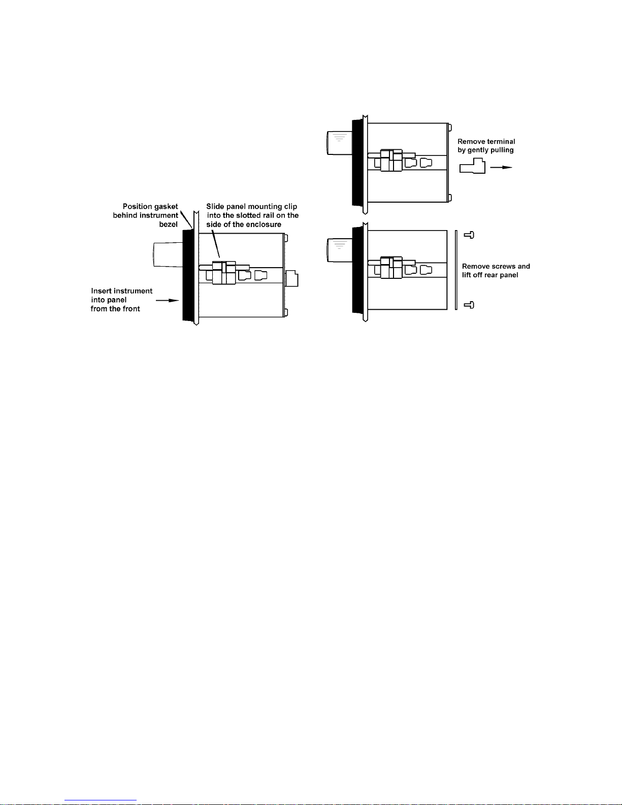
a. Insert the BA505C set point station into the
panel aperture from the front. Ensure that
the gasket is correctly positioned behind the
bezel.
Page 5
5
b. Fix two panel mounting clips to opposite
sides of the instrument and tighten until the
indicator is secured as shown in Fig 4.
c. Connect the panel wiring to the rear terminal
block(s) as shown in Fig 3. To simplify
installation, the terminals are removable so
that the panel wiring can be completed
before the instrument is installed.
Fig 4 Fitting panel mounting clips
4.3 EMC
The BA505C complies with the requirements of
the European EMC Directive. For specified
immunity all wiring should be in screened twisted
pairs. The indicator enclosure may be earthed
locally by securing a tag under one of the rear
panel corner fixing screws.
5. Calibration
The front panel multi-turn control adjusts the set
point station’s output current between
approximately 3.5 and 21mA, no calibration is
required.
5.1 Internal display
The BA505C internal display may be calibrated so
that the 4/20mA loop current is shown in the
required engineering units.
The BA505C display will be supplied calibrated as
requested at time of ordering. If calibration is not
requested, the display will be set to show 00.0
with 4.000mA loop current, and 100.0 with
20.000mA loop current, but may easily be
recalibrated on-site.
The display is calibrated by plug-in links and two
multi-turn potentiometers that are accessible
through holes in the rear panel. To gain access
to the links the rear panel must be removed as
shown in Fig 5.
For maximum accuracy the display should be
calibrated using a traceable current measuring
device with an accuracy greater than 4µA.
Fig 5 Removal of rear panel
5.2 Zero adjustment
Zero is defined as the number displayed with a
4.000mA loop current, and may be adjusted
between -1000 and 1000. The zero
potentiometer has two ranges, 0 to 500 and 500 to
1000; the polarity of the zero is defined by the
position of the suppression / elevation links.
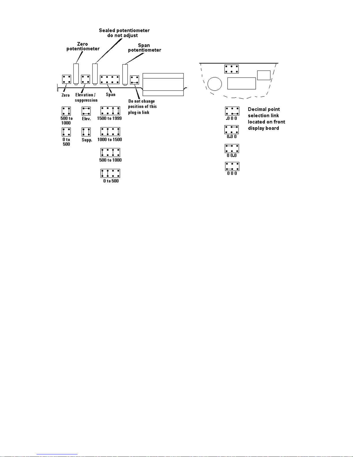
Fig 6 shows the position of the links and zero
potentiometer.
Suppression / elevation links
Elevation Positive zero 0 to 1000
or Suppression Negative zero 0 to -1000
Zero link
0 to 500
or 500 to 1000
5.3 Span adjustment
Span is defined as the difference between the
number displayed at 4.000mA and the number
displayed at 20.000mA loop current. The span
potentiometer has four ranges defined by the span
links, and may be adjusted to any number
between 0 and 1999.
Fig 6 shows the position of the links and span
potentiometer.
Span links
000 to 500
or 500 to 1000
or 1000 to 1500
or 1500 to 1999
Page 6
6
5.4 Decimal point
A dummy decimal point may be displayed
between any of the four digits. The position or
absence of this decimal point is determined by
the position of the decimal point link shown in Fig
6. When calculating the required span and zero
settings the decimal point should be ignored.
5.5 Reverse action
Normally the BA505C display increases as the
loop current increases, but this can be reversed.
Please contact BEKA associates for details.
5.6 Calibration example
A BA505C is required to display:
25.0 with at 4.000mA loop current
115.0 with at 20.000mA loop current
i.e. A zero of positive 250 Ignoring decimal
A span of 900 point
A decimal point in position 00.0
The following adjustments are required:
Step 1 The BA505C is required to display a
positive zero therefore the
suppression / elevation links should be
put in the elevation position.
Step 2 The required zero is 250, therefore the
zero link should be put in the 0 to 500
position.
Step 3 The required span is 900, therefore the
span links should be placed in the 500
to 1000 position.
Step 4 The decimal point is required between
the least two significant digits,
therefore the decimal point link should
be placed in the 00.0 position.
Step 5 Adjust the BA505C front panel control
until the external current measuring
device indicates that the loop current is
4.000mA. Adjust the zero
potentiometer at the rear of the
BA505C until the BA505C displays
25.0
Step 6 Adjust the BA505C front panel control
until the external current measuring
device indicates that the loop current is
20.000mA. Adjust the span
potentiometer at the rear of the
BA505C until the BA505C displays
115.0
Step 7 Repeat steps 5 and 6 until both
calibration points are correct. The
span and zero controls are almost
independent so it should only be
necessary to repeat each adjustment
twice.
Fig 6 Position of calibration plug-in links and potentiometers
]
Page 7

7
5.7 Over and under-range
The BA505C can be calibrated to display numbers
between -1999 and 1999. If this range is
exceeded the three least significant digits will be
blanked. Under-range is indicated by -1 and
over-range by 1.
6. Maintenance
6.1 Fault finding during commissioning
If the BA505C set point station fails to function
during commissioning the following procedure
should be followed:
Symptom Cause Solution
No loop Incorrect Check wiring
current wiring or no and power
power supply supply polarity
Unstable Insufficient Check that voltage
loop supply between terminals
current voltage 1 & 3 is between 6.1
and 30V
BA505C Positive The display has been
displays 1 over-range incorrectly calibrated
& is trying to show a
number greater than
1999.
BA505C Negative The display has been
displays -1 over-range incorrectly calibrated
& is trying to show a
number less than
-1999.
Unstable Power supply Reduce ripple
display has voltage.
ripple
6.2 Fault finding after commissioning
ENSURE PLANT SAFETY BEFORE
STARTING MAINTENANCE
If a BA505C fails after it has been functioning
correctly, the following procedure should be
followed:
Symptom Cause Solution
No loop Wiring or Check wiring
current power supply and power
fault supply
Unstable Insufficient Check that
loop supply voltage between
current voltage terminals 1 & 3
is between and
6.1 & 30V
Unstable Power supply Reduce ripple
display has developed
voltage ripple
If this procedure does not reveal the cause of the
fault, it is recommended that the BA505C manual
set point station is replaced with a spare
instrument.
6.3 Servicing
The BA505C is difficult to service to component
level on-site. All BA505C set point stations are
interchangeable, and a single spare assembly can
be used to replace any instrument which fails.
We recommend that, except under exceptional
circumstances, suspect instruments are returned
to BEKA associates or our local agent for repair.
6.4 Guarantee
Set point stations which fail within the guarantee
period should be returned to BEKA associates or
our local agent. It is helpful if a brief description of
the fault symptoms is provided.
6.5. Customer comments
BEKA associates is always pleased to receive
comments from customers about our products and
services. All communications are acknowledged
and whenever possible, suggestions are
implemented.
Page 8

8
7. Accessories
7.1 Scale card
The BA505C has a window below the multi-turn
control knob to accommodate a scale card. The
instrument can be supplied with a printed scale
card showing any units specified at the time of
ordering e.g.
o
C, mBar, RPM. If a printed scale
card is not requested, a blank card will be
supplied.
Scale cards can easily be marked on site as
follows:
a. Remove the rear terminal block(s) and the
rear panel as shown in Fig 5.
b. Remove the end cap of the front panel
control knob that will reveal a screw head.
Loosen this screw and carefully pull the
control knob from the shaft.
c. Pull the electronic assembly from the rear of
the enclosure.
d. Remove the blank scale card and mark with
the required legend. Replace scale card
taking care to align it within the front panel
window.
e. Slide the electronic assembly into the rear of
the enclosure and guide the control shaft
carefully through the front panel seal.
Replace the rear panel and terminals.
f. Replace the control knob, tighten the
retaining screw and replace the control knob
end cap.
7.2 Tag strip
The BA505C can be supplied with a thermally
printed tag strip secured by rivets to the rear
panel. This tag strip is not visible from the front of
the instrument after installation.
 Loading...