

Page 1
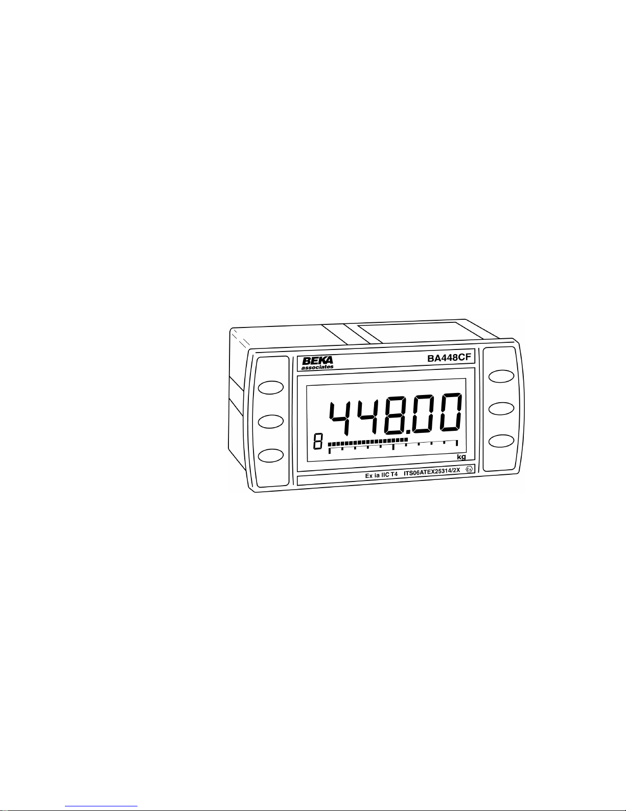
Issue: 3
23rd June 2011
BA448CF-F
FOUNDATION™ fieldbus
Intrinsically safe
Panel mounting
8 variable
Fieldbus Indicator
Issue 3
Page 2

2
1. Description
1.1 Documentation
2. Operation
2.1 Error messages
3. Intrinsic Safety Certification
3.1 ATEX certificate
3.2 Zones, gas groups and T rating
3.3 Fieldbus connection
3.4 Certification Iabel Information
4. System Design for Hazardous Area
4.1 FISCO Systems
4.2 Non-FISCO Sysems
5. Installation
5.1 Location
5.2 Installation procedure
5.3 EMC
6. Configuration
6.1 Configuration menus
6.2 Node configuration menu
6.2.1 Reset to node factory defaults
6.2.2 Change from node to listener
6.2.3 Access code for node
configuration menu.
6.3 Listener configuration menu
6.3.1 Access
6.3.2 Summary of listener functions
6.3.3 Scan fieldbus segment
6.3.4 List configured input
parameters.
6.3.5 Enter address & display
parameters.
6.3.6 Enable selected input
6.3.7 Enter Device Address
6.3.8 Enter Variable Identity
6.3.9 Decimal point position
6.3.10 Configuration of bargraph
6.3.11 Scale numeric display
6.3.12 Access code for listener
configuration menu.
6.3.13 Change from listener to node
6.3.14 Reset the indicator to listener
factory defaults.
7. Maintenance
7.1 Fault finding during commissioning
7.2 Fault finding after commissioning
7.3 Servicing
7.4 Routine maintenance
7.5 Guarantee
7.6 Customer comments
8. Accessories
8.1 Scale and Tag marking
8.2 Tag plate
8.3 Pipe mounting kits
Appendix 1
FM Approval for use in the USA and
cFM Approval for use in Canada.
Appendix 2
IECEx certification
CONTENTS
The BA448CF-F is CE marked to show compliance with the European Explosive Atmospheres
Directive 94/9/EC and the European EMC Directive 2004/108/EC
Page 3

3
1. DESCRIPTION
The BA448CF-F fieldbus indicator is an intrinsically
safe FOUNDATION™ fieldbus instrument that may
be configured as a fieldbus node or as a fieldbus
listener. It can display up to eight fieldbus process
variables on a five digit LCD and 31 segment
analogue bargraph. The instrument is bus
powered so no additional power supply is required.
As a fieldbus node the indicator is configured via
the fieldbus host.
Communication Fieldbus Function
Protocol Blocks
FOUNDATION™ fieldbus Input Selector (2 x IS)
Digital input (6 x DI)
Device Description files may be downloaded from
the Fieldbus Foundation or from the BEKA
associates websites.
When configured as a fieldbus listener the
BA448CF-F is not visible to the fieldbus host and
can only be configured using the push buttons on
the front of the instrument.
Housed in a robust 72 x 144 panel mounting DIN
enclosure, the BA448CF-F fieldbus indicator has
an IP66 front panel and is supplied with a gasket to
seal the joint between the instrument and the
panel.
The instrument is intrinsically safe and has been
certified by European Notified Body Intertek
Testing and Certification Ltd (ITS) to harmonised
ATEX explosive gas standards, which has been
used to confirm compliance with European ATEX
Directive 94/9/EC.
The BA448CF-F also has intrinsic safety and
nonincendive FM and cFM Approval allowing
installation in the USA and Canada – see
Appendix 1.
For international applications the BA448CF-F
fieldbus indicator has IECEx intrinsic safety
approval – see Appendix 2.
The instrument’s communication protocol is shown
on the rear of the instrument. The ‘-F’ order code
suffix also indicates the protocol but is not shown
on the instrument certification label. There is an
alternative version of the fieldbus display, order
code BA448CF-P for use on PROFIBUS PA
networks.
1.1 Documentation
This instruction manual describes ATEX system
design and installation of the BA448CF-F fieldbus
indicator.System design information for non-ATEX
approvals is shown in appendices to this manual.
2. OPERATION
The BA448CF-F fieldbus indicator can display up
to eight pre-configured FOUNDATION™ fieldbus
process variables designated in-1 to in-8. The
operator can select which variable is displayed
using the ▼and ▲ push buttons which scroll the
display through the eight inputs. A numeric
annunciator on the left hand side of the display
shows which of the eight inputs is currently being
displayed.
2.1 Error messages
When the BA448CF-F is configured as a listener
the following error messages may be displayed:
‘no ConF’ No inputs have been
configured or are enabled.
‘no dAtA’ No data is being received
with the current configuration.
3. INTRINSIC SAFETY CERTIFICATION
3.1 ATEX certificate
The BA448CF-F has been issued with an EC-Type
Examination Certificate by Notified Body Intertek
Testing and Certification Ltd (ITS) that has been
used to confirm compliance with the European
ATEX Directive 94/9/EC for Group II, Category 1G,
gas atmospheres, Ga Ex ia IIC T4. The instrument
bears the Community Mark and, subject to local
codes of practice, may be installed in any of the
European Economic Area (EEA) member
countries. ATEX certificates are also acceptable
for installations in Switzerland.
This manual describes ATEX installations in
explosive gas atmospheres that conform with
EN 60079:Part14 Electrical Installation in
Hazardous Areas. When designing systems for
installation outside the UK, the local Code of
Practice should be consulted.
Page 4

4
3.2 Zones, gas groups and T rating
The BA448CF-F has been issued with EC Type
Examination certificate ITS06ATEX25314/2X
which has been used to confirm compliance with
the requirements for Group II Category 1G Ga Ex
ia IIC T4 (Tamb –40 to 70oC) specified in the
ATEX Directive. When connected to a suitable
certified system the BA448CF-F may be installed
in:
Zone 0 explosive gas air mixture
continuously present.
Note: Special conditions for
safe use apply see section 5.1
Zone 1 explosive gas air mixture
likely to occur in normal
operation.
Zone 2 explosive gas air mixture not
likely to occur, and if it does will
only exist for a short time.
Be used with gases in groups:
Group A propane
Group B ethylene
Group C hydrogen
Having a temperature classification of:
T1 450oC
T2 300oC
T3 200oC
T4 135oC
At an ambient temperature between –40 and
+70oC.
Note: minimum guaranteed operating temperature
is –20ºC.
3.3 Fieldbus connection
The BA448CF-F Indicator is powered and
communicates via the fieldbus, which is connected
to terminals 1 and 2. These are non-polarised,
comply with the Fieldbus Intrinsically Safe Concept
(FISCO) defined in EN 60079 Part 27 and have
separate entity parameters shown below:
FISCO Entity
Ui = 17.5V dc 22.0V dc
Ii = 380mA dc 250mA dc
Pi = 5.32W 1.2W
The maximum equivalent capacitance and
inductance at terminals 1 & 2 is:
Ci = 0
Li = 8µH
3.4 Certification Label Information
The certification information label is fitted to the top
outer surface of the enclosure. It shows details of
the ATEX certification and a statement that the
instrument is a FISCO Field Device, plus BEKA
associates name and location. IECEx approval
information is also included. The label may also
contain non-European certification information.
The instrument serial number and year of
manufacture are shown on the rear panel adjacent
to the terminals.
Page 5
5
4. SYSTEM DESIGN FOR HAZARDOUS
AREAS
4.1 FISCO Systems
The BA448CF-F may be connected to any ATEX
certified FISCO compliant fieldbus segment,
providing the segment can supply the additional
13mA required to power the instrument.
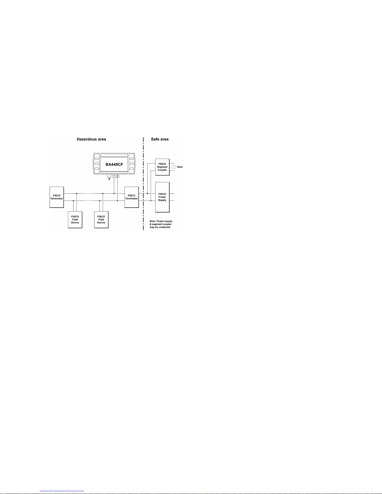
Fig 1 shows a typical fieldbus segment. To comply
with FISCO requirements, the power supply,
terminators, field devices and the interconnecting
cables must conform to EN 60079 part 27.
Fig 1 FISCO fieldbus system
4.2 Non-FISCO Systems
For non-FISCO applications the BA448CF-F
Fieldbus Indicator has a higher voltage entity
intrinsic safety input parameter allowing connection
to a wide range of fieldbus segments.
The BA448CF-F Fieldbus Indicator may be
connected to any intrinsically safe segment
providing:
The device powering the fieldbus segment is
ATEX certified and has output parameters
equal to or less than:
Uo = 22V dc
Io = 250mA dc
Po = 1.2W
The segment can provide an additional
13mA to power the Fieldbus Indicator.
Note: The equivalent capacitance Ci of the
BA448CF-F Fieldbus Indicator is zero and the
equivalent inductance is insignificant. Therefore
these BA448CF-F safety parameters do not need
to be considered.
Page 6

6
5. INSTALLATION
5.1 Location
The BA448CF-F is housed in a robust aluminium
enclosure with a toughened glass window mounted
in a Noryl bezel. The front of the instrument
provides IP66 protection and a gasket seals the
joint between the instrument enclosure and the
panel. The instrument may be installed in any
panel providing the environmental limits shown in
the specification are not exceeded.
Fig 2 shows the overall dimensions of the
BA448CF-F and the panel cut-out. To achieve an
IP66 seal between the instrument enclosure and
the panel, the smaller cut-out must be used and
the instrument secured with four panel mounting
clips.
CAUTION
Installation in Zone 0
When installed in a Zone 0 potentially
explosive atmosphere requiring apparatus
of Category 1G, the indicator shall be
installed such that even in the event of rare
incidents, an ignition source due to impact
or friction between the aluminium enclosure
at the rear of the instrument mounting panel
and iron/steel is excluded.
Fig 2 BA448CF-F dimensions
5.2 Installation Procedure
a. Insert the BA448CF-F into the instrument
panel cut-out from the front of the panel.
b. Fix panel mounting clips to opposite sides of
the instrument and tighten until the
instrument is secure. Four clips are required
to achieve an IP66 seal between the
instrument enclosure and the panel.
c. Connect the panel wiring to the rear terminal
block as shown in Fig 3. To simplify
installation, the terminals are removable so
that panel wiring can be completed before
the instrument is installed.
Fig 3 Installation and terminal connections
5.3 EMC
The BA448CF-F complies with the requirements of
the European EMC Directive 2004/108/EC. For
specified immunity, all wiring should be in
screened twisted pairs with the screens earthed at
one point in the safe area.
Page 7

7
6. CONFIGURATION
The BA448CF-F 8 variable FOUNDATION™
fieldbus indicator may be configured as a fieldbus
node or as a fieldbus listener. When used as a
fieldbus node the indicator is configured via the
fieldbus host. For detailed node conditioning
information please refer to the BEKA
FOUNDATION™ fieldbus Interface Guide which
may be downloaded from www.beka.co.uk
As a fieldbus listener the BA448CF-F is not visible
to the fieldbus host and can only be configured via
the front panel push buttons using the menu
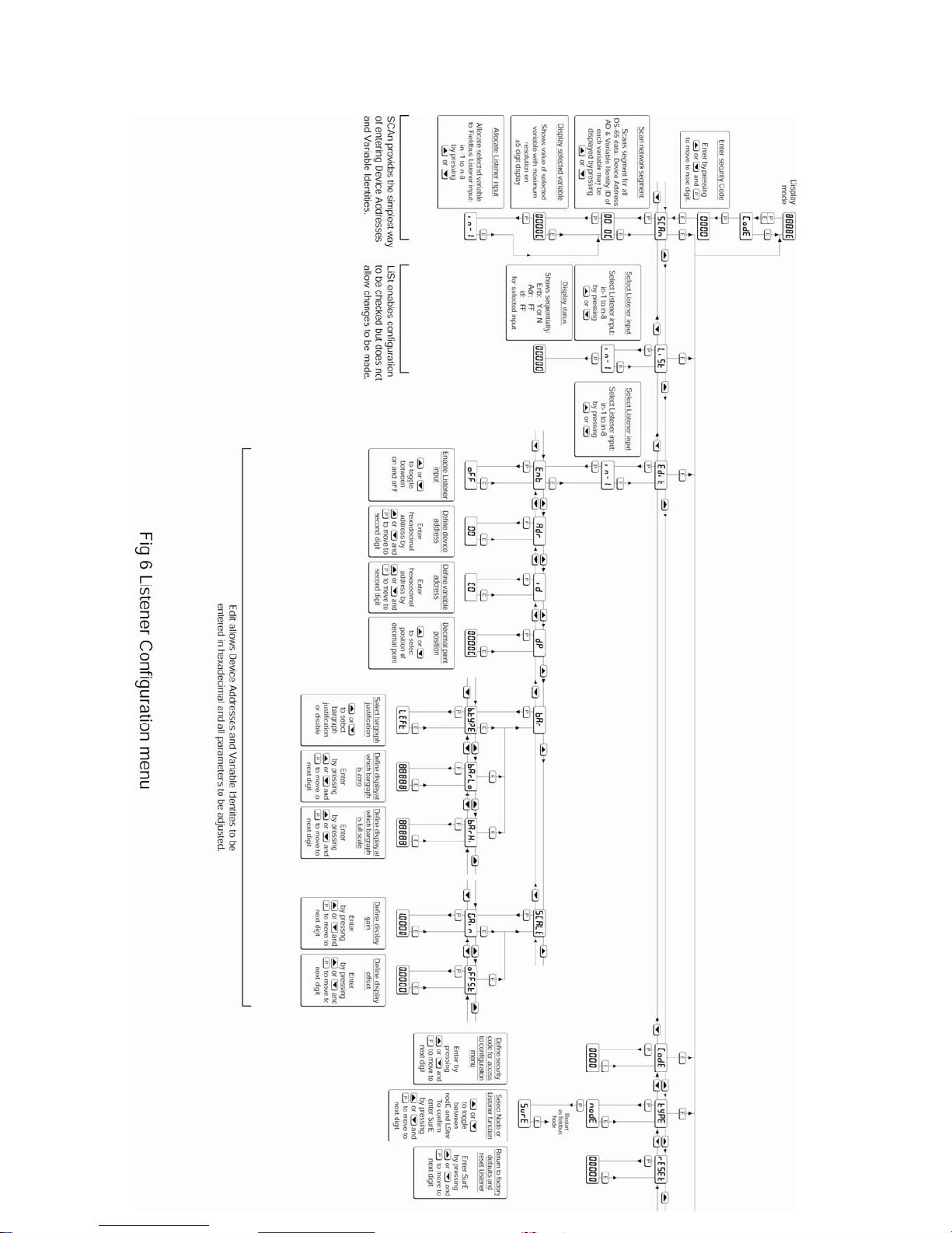
shown in Fig 6.
Throughout this manual the four BA448CF-F push
buttons are identified P E ▼ ▲ and legends
displayed by the fieldbus indicator are shown
within inverted commas e.g. ‘CodE’ and ‘LiSt’.
6.1 Configuration menus
The configuration menu is separated into two
sections, fieldbus node and fieldbus listener. Both
contain the ‘tYPE’ function that enables transfer
between the two. Unless otherwise requested
when ordered, all FOUNDATION™ fieldbus
BA448CF-F indicators are supplied as fieldbus
nodes but can easily be reconfigured on-site.
6.2 Node configuration menu
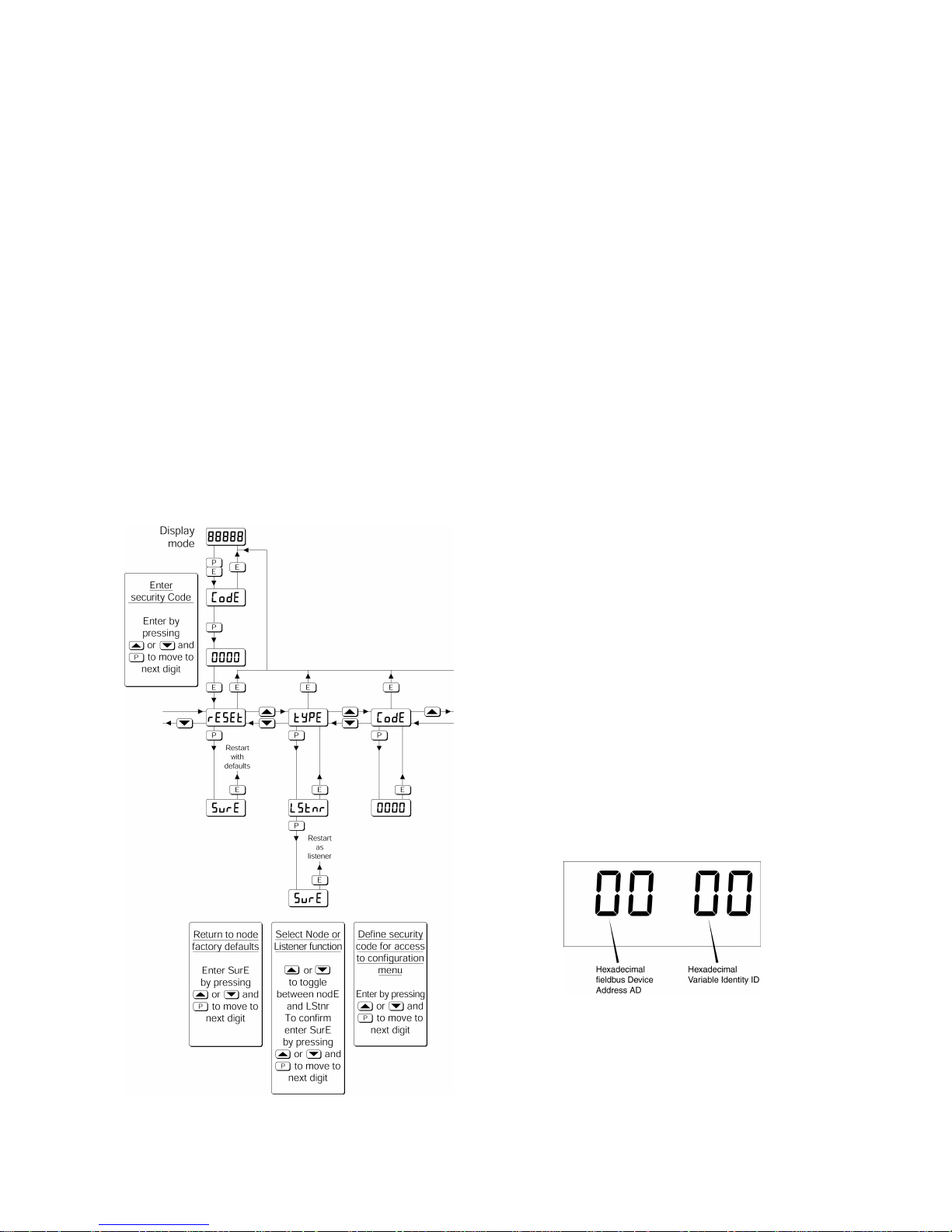
The node configuration menu is shown in Fig 4.
Access to the menu is obtained by operating the P
and E buttons simultaneously. If the BA448CF-F
is not protected by an access code the first
parameter 'rESEt’ will be displayed*. If the
instrument is protected by an access code, ‘CodE’
will be displayed first. Pressing P will allow the
four digit security code to be entered digit by digit
using the ▼ or ▲ button to adjust the flashing digit
and P to move control to the next digit. When the
correct code has been entered, pressing E will
cause the first parameter ‘rESEt’ to be displayed*.
If an incorrect code is entered, or no button is
pressed for ten seconds, the BA448CF-F will
automatically return to the display mode.
* If the indicator displays ‘SCAn’ it is conditioned
as a fieldbus listener, see section 6.3.13 to change
it to a fieldbus node.
6.2.1 Reset the indicator to node factory
defaults ‘rESEt’
The BA448CF-F may be reset to the factory
defaults that are shown below:
Security Code 0000 (disabled)
Device address Unconfigured
Last variable 8
For each of the eight inputs:
Decimal point XXX.XX
Bar Type Left
Bar lower limit 0.0
Bar Upper limit 100.0
Gain 1.0
Offset 0.0
To reset the BA448CF-F select ‘rESEt’ in the
configuration menu by operating the ▼ or ▲
button. To enter the function press P which will
reveal ‘0000’ with the left hand digit flashing. To
prevent accidental use of this function, ‘5urE’ must
be entered to confirm that the instrument is to be
reset.
Using the ▼ or ▲ button set the flashing digit to ‘5’
and press the P button to move control to the next
digit which should be set to ‘u’. When the four
letters of ‘5urE’ have been entered operating the E
button will reset the BA448CF-F to the factory
defaults.
CAUTION
All the instrument’s node configuration
and links will be lost when it is reset.
6.2.2 Change from node to listener ‘tYPE’
This function enables the instrument to be
changed from a fieldbus node to a fieldbus listener.
Select ‘tYPE’ in the node configuration menu using
the ▼ or ▲ button. To enter the function press P
which will show that the instrument is configured
as a fieldbus node, to change to a fieldbus listener
press the ▼ or ▲ button which will toggle the
display to ‘LStnr’ To prevent accidental changes
this request must be confirmed by operating the P
button and entering ‘5urE’. The instrument will
display ‘0000’ with the first digit flashing, using the
▼ or ▲ button set the flashing digit to ‘5’ and press
the P button to move control to the next digit which
should be set to ‘u’. When the four letters of ‘5urE’
have been entered, operating the E button will
cause the instrument to restart as a fieldbus
listener in the display mode.
CAUTION
All the instrument’s node configuration
and links will be lost when it is changed
from a fieldbus node to a fieldbus
listener.
Page 8
8
6.2.3 Access code for node configuration
menu ‘CodE’
Access to the node configuration menu may be
protected by a four digit security code which must
be entered to gain access. New instruments are
supplied configured with the default code 0000
which disables this protection and allows
unrestricted access to the configuration menu.
To enter a new access code select ‘CodE’ in the
configuration menu by operating the ▼ or ▲
button. To enter the function press P which will
reveal the current access code with one digit
flashing. The code may be changed using the ▼ or
▲ button to adjust the flashing digit and the P
button to move control to the next digit. When the
required code has been selected, press E to enter
the selection and return to the ‘CodE’ prompt in the
configuration menu. The revised access code will
be activated when the indicator is returned to the
display mode.
If the access code is lost please contact BEKA
associates.
Fig 4 Node configuration menu
6.3 Listener configuration menu
The listener configuration menu is separated into
three sections, ‘SCAn’, ‘LISt’ and ‘Edit’, plus three
housekeeping functions ‘CodE’, ‘tYPE’ and ‘rESEt’
as shown in Fig 6.
‘SCAn’ is the simplest method of configuration if
the fieldbus Device Address and Variable Identity
of the data to be displayed by the BA448CF-F
listener are not known.
In the ‘SCAn’ function pressing the P button
causes the BA448CF-F indicator to search the
fieldbus segment to which it is connected for all
publishers. Fig 5 shows how the indicator displays
the hexadecimal Device Address and Variable
Identity associated with each publisher.
A Publisher is a device that places it's output
data onto the bus as part of a cyclical predetermined data exchange schedule.
The Device Address is a unique address that
identifies each fieldbus instrument connected to
the bus.
The Variable Identity is the fieldbus device
Data Link Connection End Point (DLCEP)
which identifies each Function Block output
(process variable) transmitted by a fieldbus
device such as flow and temperature
transmitted by a fieldbus flowmeter.
The ▼ and ▲ push buttons scroll the display
through all the publishers on the segment showing
the Device Address and Variable Identity for each
one - see Fig 5. To aid identification, operating
the P button will preview the value of the data at
each selected address, if required it may then be
allocated to one of the eight BA448CF-F listener
inputs in-1, to in-8 by operating the P button again.
If the format of the data at the selected Device
Address and Variable Identity is not DS-65 (float +
status) ‘no dAt’ will be displayed.
Fig 5 Device Address and Variable Identity
If the Device Address and Variable Identity of the
process variable to be displayed by the BA448CFF indicator are known, they may be directly
entered via the edit sub-menu. This sub-menu
also provides full control of both the numeric and
bargraph display parameters.
Page 9

9
6.3.1 Access
Access to the listener configuration menu is
obtained by operating the P and E buttons
simultaneously. If the BA448CF-F is not protected
by an access code the first parameter 'SCAn’ will
be displayed.* If the indicator is protected by an
access code, ‘CodE’ will be displayed first.
Pressing P will allow the four digit security code to
be entered digit by digit using the ▼ or ▲ button to
adjust the flashing digit and P to move control to
the next digit. When the correct code has been
entered, pressing E will cause the first parameter
‘SCAn’ to be displayed.* If an incorrect code is
entered, or no button is pressed for ten seconds,
the indicator will automatically return to the display
mode.
* If the indicator displays ‘rESEt’ it is conditioned
as a fieldbus node, see section 6.2.2 to change it
to a fieldbus listener.
6.3.2 Summary of listener configuration
functions.
This section contains a summary of all the listener
configuration functions including a reference to
more detailed information. It should be read in
conjunction with Fig 6.
Indicator Summary
display of function
‘SCAn’ Scan fieldbus segment
Identifies all publishers on the fieldbus
segment to which the listener is
connected and enables selected data to
be allocated to one of the eight listener
inputs.
See section 6.3.3
‘LiSt’ List configured input parameters
For each of the eight BA448CF-F
listener input, in-1 to in-8 shows if the
input is enabled and the allocated
Device Address and Variable Identity.
Parameters can not be changed from
within this function.
See section 6.3.4
‘Edit’ Enter addresses and display
parameters
Contains six sub-functions that enable
known fieldbus Device Address and
Variable Identity to be entered and all
display parameters adjusted for each of
the eight fieldbus listener inputs.
See section 6.3.5
‘Enb’ Enable listener input
Each of the eight listener inputs in-1
to in-8 may be enabled or disabled
without affecting any parameters.
See section 6.3.6
‘Adr’ Enter fieldbus Device Address
Allows hexadecimal fieldbus device
address for each of the eight listener
inputs in-1 to in-8 to be entered.
See section 6.3.7
‘id’ Enter Variable Identity
Allows hexadecimal Variable Identity
for each listener input in-1 to in-8 to
be entered.
See section 6.3.8
‘dP’ Decimal point position
Defines position of displayed decimal
point for each listener input in-1 to
in-8.
See section 6.3.9
‘bAr’ Configuration of bargraph display.
Defines bargraph type, plus digital
display at which bargraph is zero and
full scale for each listener input in-1 to
in-8.
See section 6.3.10
‘SCALE’ Scale numeric display
Applies zero offset and scale factor to
the numeric display for each listener
input in-1 to in-8.
See section 6.3.11
‘CodE’ Access code for listener
configuration menu
Enters a four digit security access
code for configuration menu. Default
code 0000 disables this function.
See section 6.3.12
‘tYPE’ Change from listener to node
Changes the function of the fieldbus
indicator from a listener to a node.
See section 6.3.13
‘rESEt’ Reset
Returns the BA448CF-F listener to
factory defaults.
See section 6.3.14
Page 10
10
Page 11

11
6.3.3 Scan fieldbus segment ‘SCAn’
If the Device Address and Variable Identity of a
process variable are not known, the ‘SCAn’
function provides a simple way to identify them.
This function scans the fieldbus segment to which
the BA448CF-F indicator is connected and
identifies all the publishers. To aid identification it
enables the value of each process variable to be
pre-viewed and, if required, allocated to one of the
eight BA448CF-F Fieldbus indicator inputs.
The BA448CF-F indicator only supports DS-65
formatted data (float + status) which is the usual
format for analogue process variables. The
‘SCAn’ function will identify all publishers on the
segment irrespective of format, but when previewed, non DS-65 formatted data will produce a
‘no dAt’ error message.
‘SCAn’ is the first function displayed when entering
the listener configuration menu, or it may be
selected from within the menu by operating the ▼
or ▲ button. To scan the fieldbus segment to
which the indicator is connected for all published
data press P which will reveal the hexadecimal
Device Address and Variable Identity of the first
publisher found as shown in Fig 5. If there is
more than one publisher operating the ▼ or ▲
button will scroll though all of them.
If no cyclic data is being published on the fieldbus
segment the BA448CF-F indicator will display
‘noPub’.
When the Device Address and Variable Identity of
a process variable is being displayed, pressing P
will preview the value of the process variable
displayed with maximum resolution on the five digit
display. If this confirms that it is one of the
process variables to be displayed, it may be
allocated to one of the eight BA448CF-F listener
inputs in-1 to in-8.
To select the required listener input press P to
display the first input in-1, operating the ▼ or ▲
button will scroll the display through the other
inputs. When the required input is displayed
pressing E will allocate the selected process
variable to the selected input and return the display
to the Device Address and Variable Identity from
which another process variable may be selected.
When a process variable is allocated to a indicator
input any previous allocation will be overwritten.
6.3.4 List configured input parameters ‘LiSt’
The ‘LiSt’ function enables the Device Address and
Variable Identity allocated to each lindicator input
to be viewed without danger of it being accidentally
changed.
The ‘LiSt’ function may be selected from within the
menu by operating ▼ or ▲ button. To enter the
function press P which will display the indicator
input currently selected in the display mode, other
inputs may be selected using the ▼ or ▲ button.
Operating the P button will cause the following
parameters for the selected input to be displayed
sequentially:
Display Explanation
‘Enb: Y or N’ Input Enabled yes or no
‘Adr: 00’ Device Address
‘id: 00’ Variable Identity
The display then automatically returns to the
selected BA448CF-F indicator input from where
another input may be selected.
If one of the eight BA448CF-F indicator’s inputs in1 to in-8 has not had a Device Address and
Variable Identity allocated to it, ‘LiSt’ will show both
as invalid address FF.
6.3.5 Enter address & display parameters
‘Edit’
The ‘Edit’ function may be selected from within the
menu by operating ▼ or ▲ button. To enter the
function press P which will display the indicator
input currently selected in the display mode, other
listener inputs may be selected using the ▼ or ▲
button. When the required input has been
selected operating the P button will enter the edit
sub-menu at ‘Enb’ for the selected input.
6.3.6 Enable selected input ‘Enb’
‘Enb’ turns the indicator input selected in the Edit
function on or off without affecting the conditioning.
To enter the function press P which will reveal
whether the selected input is ‘on’ or ‘oFF’.
Operating the ▼ or ▲ buttons will toggle between
the two conditions. When set as required
operating the E button will enter the selection and
return to the edit sub-menu.
Page 12

12
6.3.7 Enter Device Address ‘Adr’
This function allows a known fieldbus Device
Address to be entered and allocated to the
indicator input selected in the Edit function. To
enter the function press P which will reveal the
existing two digit hexadecimal address with one
digit flashing which may be changed by operating
the ▼ or ▲ button. When set as required
operating the P button will transfer control to the
second digit that may be adjusted in the same
way. When both digits are set as required
operating the E button will enter the selection and
return to the ‘Adr’ prompt in the edit sub-menu.
6.3.8 Enter Variable Identity ‘id’
Enables a known Variable Identity to be entered
and allocated to the indicator input selected in the
Edit function. To enter the function press P which
will reveal the existing two digit hexadecimal
address with one digit flashing which may be
changed by operating the ▼ or ▲ button. When
set as required operating the P button will transfer
control to the second digit that may be adjusted in
the same way. When both digits are set as
required operating the E button will enter the
selection and return to the ‘id’ prompt in the edit
sub-menu.
6.3.9 Decimal point position ‘dP’
Defines the position the decimal point in the
numeric display. To enter the function press P
which will reveal the existing decimal point
position. Operating the ▼ or ▲ button will move
the decimal point to the required position, omit it,
or activate all the decimal points which
automatically provides maximum resolution in the
display mode irrespective of the numeric value.
When positioned as required, operating the E
button will enter the selection and return to the ‘dP’
prompt in the edit sub-menu.
6.3.10 Configuration of bargraph display
‘bAr’
This function contains three sub-functions that
enable the bargraph, justify its position and define
the relationship between the bargraph and the
instrument’s numeric display.
Sub-function ‘b.tYPE’ allows the bargraph to be
left, centre or right justified, or to be turned off.
Sub-functions ‘bArLo’ and ‘bArhi’ define the
listener’s numeric display at which the bargraph
starts and is at full scale.
The ‘bAr’ function may be selected from within the
edit sub-menu by operating the ▼ or ▲ button.
To enter the function press P which will display the
‘b.tYPE’ sub-function, pressing P again will reveal
the existing bargraph justification.
The ▼ or ▲ button will scroll through the four
options, when the required justification is
displayed, pressing E will enter the selection and
return the display to the ‘b.tYPE’ prompt in the edit
sub-menu from which ‘bArLo’ may be selected
using the ▼ or ▲ button.
‘bArLo’ defines the indicator’s numeric display at
which the bargraph starts, to enter the function
press P which will reveal the existing setting. The
display may be changed using the ▼ or ▲ button
to adjust the flashing digit and the P button to
move control to the next digit. When the required
starting display has been selected, press E to
return to the ‘bArLo’ prompt in the edit sub-menu
from which the ‘bArHi’ function may be selected.
‘bArHi’ defines the indicator’s numeric display at
which the bargraph is full scale, to enter the
function press P which will reveal the existing
setting. The display may be changed using the ▼
or ▲ button to adjust the flashing digit and the P
button to move control to the next digit. When the
required display has been selected, press E twice
to enter the new values and return to the ‘bAr’
prompt in the edit sub-menu.
Note: If the ‘dP’ function has been set to provide
automatic maximum resolution irrespective of the
displayed value, it may be necessary to manually
position the decimal point before adjusting ‘bArLo’
or ‘bArHi’. This can be achieved by repeatedly
operating the P button until the activated decimal
point flashes, the decimal point can then be
positioned using either the ▼ or ▲ button.
Pressing the P button again will return control to
one of the digits.
6.3.11 Scale numeric display ‘SCALE’
A scaling factor ‘Gain’ and an offset ‘oFFSt’ may
be applied to the fieldbus process variable using
this function, thus allowing the indicator to display
the fieldbus process variable in alternative units.
The ‘SCALE’ function may be selected from within
the edit sub-menu by operating the ▼ or ▲ button.
To enter the function press P which will display the
‘GAin’ sub-function, pressing P again will reveal
the existing gain with one digit flashing. This
flashing digit may be changed by operating the ▼
or ▲ button; when adjusted the P button will move
control to the next digit or to the decimal point
which can be positioned using the ▼ or ▲ button.
When ‘GAin’ has been set to the required value
operating the E button will enter the selection and
return to the ‘GAin’ prompt in the sub-menu from
where the ‘oFFSt’ function can be selected using
the ▼ or ▲ button.
Page 13

13
To enter the ‘oFFSt’ function press P which will
reveal the existing offset with one digit flashing.
Again the flashing digit may be changed by
operating the ▼ or ▲ button and the P button will
move control to the next digit or to the decimal
point. When ‘oFFSt’ has been set to the required
value operating the E button will enter the selection
and return to the ‘oFFSt’ prompt in the sub-menu.
Three operations of the E button will return to the
‘Edit’ function in the listener configuration menu.
6.3.12 Access code for listener configuration
menu. ‘CodE’
Access to the listener menu may be protected by a
four digit security code which must be entered to
gain access. New instruments are supplied
configured with the default code 0000 which
disables this protection and allows unrestricted
access to the configuration menu.
To enter a new access code select ‘CodE’ in the
listener configuration menu by operating the ▼ or
▲ button. To enter the function press P which will
reveal the current access code with one digit
flashing. The code may be changed using the ▼ or
▲ button to adjust the flashing digit and the P
button to move control to the next digit. When the
required code has been selected, press E to enter
the selection and return to the ‘CodE’ prompt in the
listener configuration menu. The revised access
code will be activated when the indicator is
returned to the display mode.
If the access code is lost please contact BEKA
associates.
6.3.13 Change from listener to node ‘tYPE’
This function enables the instrument to be
changed from a fieldbus listener to a fieldbus node
by selecting ‘tYPE’ in the listener configuration
menu using the ▼ or ▲ button. To enter the
function press P which will show that the
instrument is configured as a fieldbus listener, to
change to a fieldbus node press the ▼ or ▲ button
which will toggle the display to ‘nodE’ To prevent
accidental changes this request must be
confirmed by operating the P button and entering
‘5urE’. The instrument will display ‘0000’ with the
first digit flashing, using the ▼ or ▲ button set the
flashing digit to ‘5’ and press the P button to move
control to the next digit which should be set to ‘u’.
When the four letters of ‘5urE’ have been entered,
operating the E button will cause the instrument to
restart as a fieldbus node in the display mode.
CAUTION
All the instrument’s listener configuration
will be lost when it is changed from a
fieldbus listener to a fieldbus node.
6.3.14 Reset the indicator to listener factory
defaults ‘rESEt’
The BA448CF-F indicator may be reset to the
listener factory defaults shown below:
Security Code 0000 (disabled)
For each of the eight inputs:
Input enable Off
Decimal point Auto (maximum resolution)
Bar Type Left
Bar lower limit 0.0
Bar Upper limit 100.0
Gain 1.0
Offset 0.0
To reset the BA448CF-F indicator to the listener
factory defaults select ‘rESEt’ in the listener
configuration menu by operating the ▼ or ▲
button. To enter the function press P which will
reveal ‘0000’ with the left hand digit flashing. To
prevent accidental use of this function, ‘5urE’ must
be entered to confirm that the instrument is to be
reset.
Using the ▼ or ▲ button set the flashing digit to ‘5’
and press the P button to move control to the next
digit which should be set to ‘u’. When the four
letters of ‘5urE’ have been entered operating the E
button will reset the BA448CF-F to the factory
defaults. Any existing configuration and
addresses will be lost when the indicator is reset.
Page 14

14
7. MAINTENANCE
7.1 Fault finding during commissioning
If a BA448CF-F indicator fails to function during
commissioning the following procedure should be
followed:
Symptom Cause Check:
No Display Instrument not
correctly
connected or
powered.
9 to 22V between
terminals 1 & 2.
When configured
as a listener
displays
‘no ConF’
No inputs are
enabled.
Configuration of
each input.
When configured
as a listener
displays
‘no dAtA’
No data being
received with the
current
configuration.
Device Address
and Variable
Identities are
correct.
That data has
DS-65 format.
Display shows
‘9.9.9.9.9’ with all
decimal points
flashing; all
bargraph
segments
activated and
bargraph scale
flashing.
Value
over-range
Configuration.
and
decimal point
position.
Display shows
‘-9.9.9.9.9’ with
all decimal points
flashing; no
bargraph
segments
activated and
bargraph scale
flashing.
Value
under-range
Configuration
And
decimal point
position.
Display
alternates
between value
and the word
‘bAd’. Bargraph
flashes.
Status of fieldbus
variable has a
quality of ‘BAD’
or a fault state is
active.
Fieldbus
configuration.
Bargraph scale
flashes.
Process variable
is outside the
limits defined for
the bargraph.
Bargraph
configuration.
All display
segments
activated.
Display is
initialising.
This is normal
operation, after a
few seconds the
model number
followed by the
firmware version
will be displayed
prior to entering
the display
mode.
7.2 Fault finding after commissioning
ENSURE PLANT SAFETY BEFORE
STARTING MAINTENANCE
Live maintenance is permitted on
intrinsically safe equipment installed in a
hazardous area, but only certified test
equipment should be used unless a gas
clearance certificate is available.
If a BA448CF-F fails after it has been functioning
correctly, the table shown in section 7.1 may help
to identify the cause of the failure.
If this procedure does not reveal the cause of the
fault, it is recommended that the instrument is
replaced.
7.3 Servicing
We recommend that faulty BA448CF-F Fieldbus
indicators are returned to BEKA associates or to
our local agent for repair.
7.4 Routine maintenance
The mechanical and electrical condition of the
instrument should be regularly checked. Initially
annual inspections are recommended, but the
inspection frequency should be adjusted to suit the
environmental conditions.
7.5 Guarantee
Instruments which fail within the guarantee period
should be returned to BEKA associates or our local
agent. It is helpful if a brief description of the fault
symptoms is provided.
7.6 Customer comments
BEKA associates is always pleased to receive
comments from customers about our products and
services. All communications are acknowledged
and whenever possible, suggestions are
implemented.
Page 15

15
8. ACCESSORIES
8.1 Scale marking
BA448CF-F indicators are fitted with a blank
escutcheon around the liquid crystal display. If
specified when the instrument is ordered, this can
be supplied printed with units of measurement and
a scale for the horizontal bargraph.
8.2 Tag number
The BA448CF-F can be supplied with a thermally
printed tag number on the rear panel adjacent to
the terminals.
Page 16

16
APPENDIX 1
FM Approval for use in the USA and
cFM Approval for use in Canada
A1.0 Factory Mutual Approval
For installations in the USA and Canada, the
BA448CF-F has FM and cFM intrinsic safety and
nonincendive approval, project identifications
3027031 and 3027031C. Copies of the
Certificates of Compliance are available from
BEKA associates sales office and www.beka.co.uk
A1.1 Intrinsic safety approval
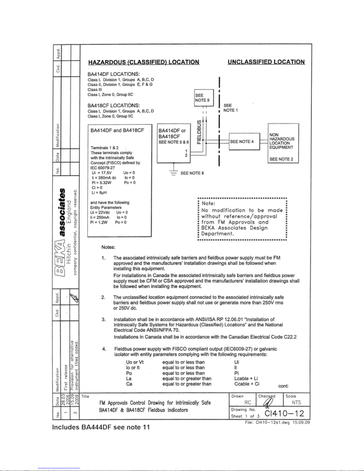
The BA448CF-F is approved to FM Class 3610
intrinsic safety standard for use in hazardous
(classified) locations. Installations must comply
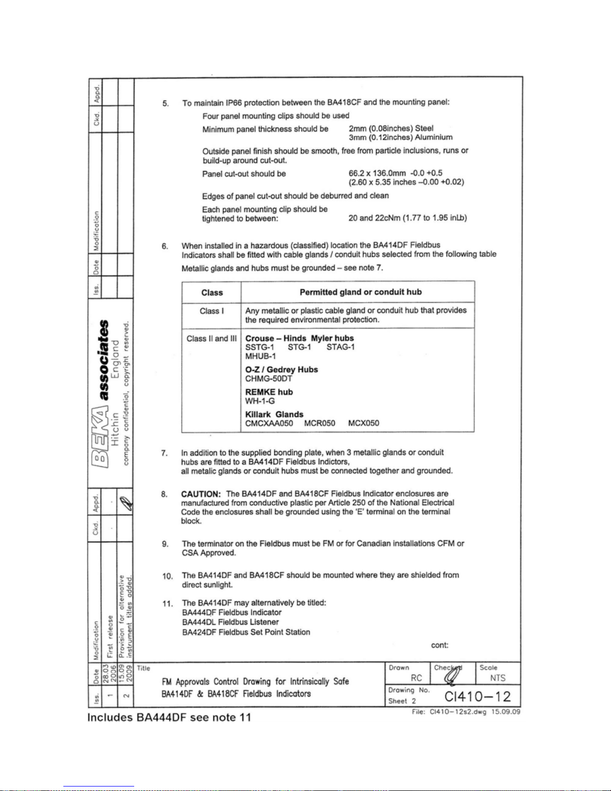
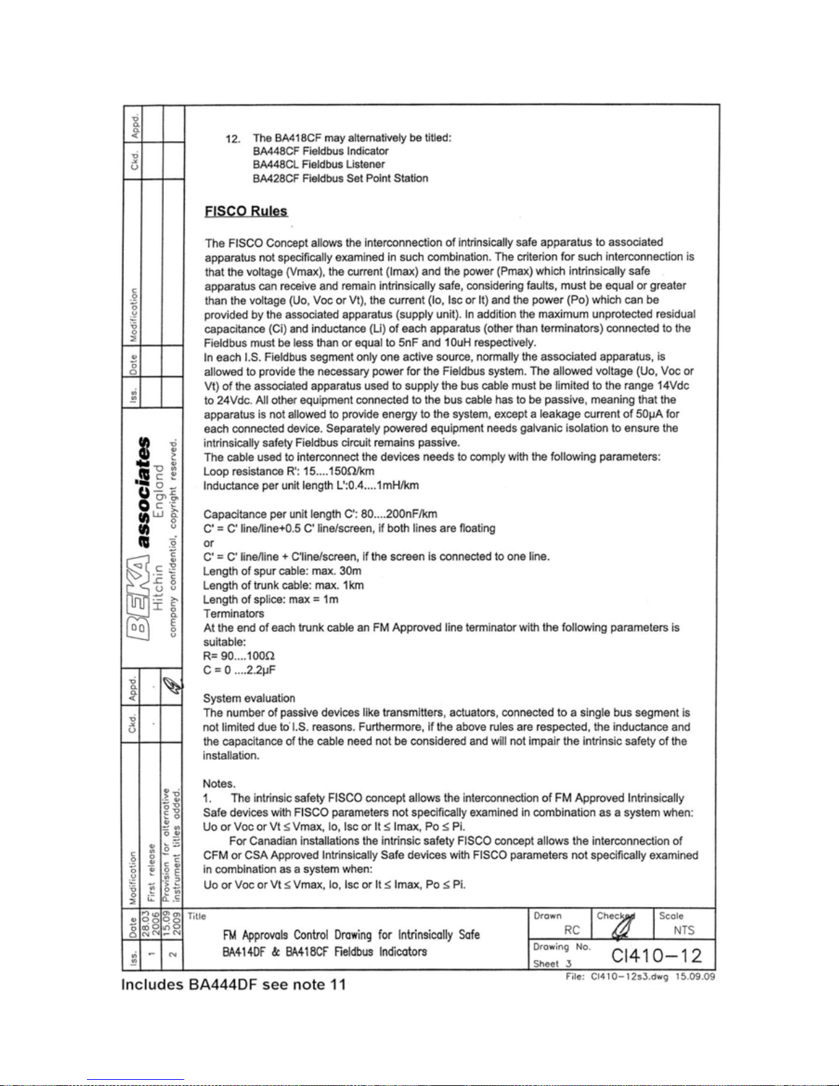
with BEKA associates Control Drawing CI410-12,
which is attached to this Appendix, ANSI/ISA
RP12.06.01 ‘Installation of Intrinsically Safe
Systems for Hazardous (Classified) Locations’ and
with the National Electrical Code ANSI/NFPA70.
Canadian installations must comply with the
Canadian Electrical Code C22.2 and with BEKA
associates Control Drawing CI410-12, which is
attached to this Appendix.
The BA448CF-F has a T4 rating at ambient
temperatures up to +70oC and may be used with
the following gases and dusts:
Intrinsic Safety
Division 1 or 2
Class I Group A & B
Group C
Group D
Class II Group E, F & G
Class III
Zone 0, 1 or 2
Class 1 Group IIC
Group IIB
Group IIA
The FM and cFM entity parameters are identical to
the ATEX parameters and, like the ATEX
certification, confirm that the BA448CF-F complies
with the FISCO Field Device requirements
specified in IEC60079-27. The intrinsically safe
system shown in Fig 1 of this manual may
therefore be used for installations in the USA and
Canada, providing the fieldbus power supply,
terminators, Zener barriers and galvanic isolators
are FM Approved for US installations and cFM or
CSA Approved for Canadian installations. All
installations must comply with BEKA associates
Control Drawing CI410-12.
FM and cFM Approvals also allows the BA448CFF to be connected to non-FISCO systems using
the entity concept – see section 4.2 of this manual.
A1.2 Nonincendive approval
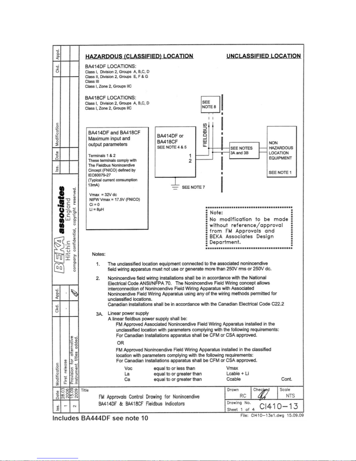
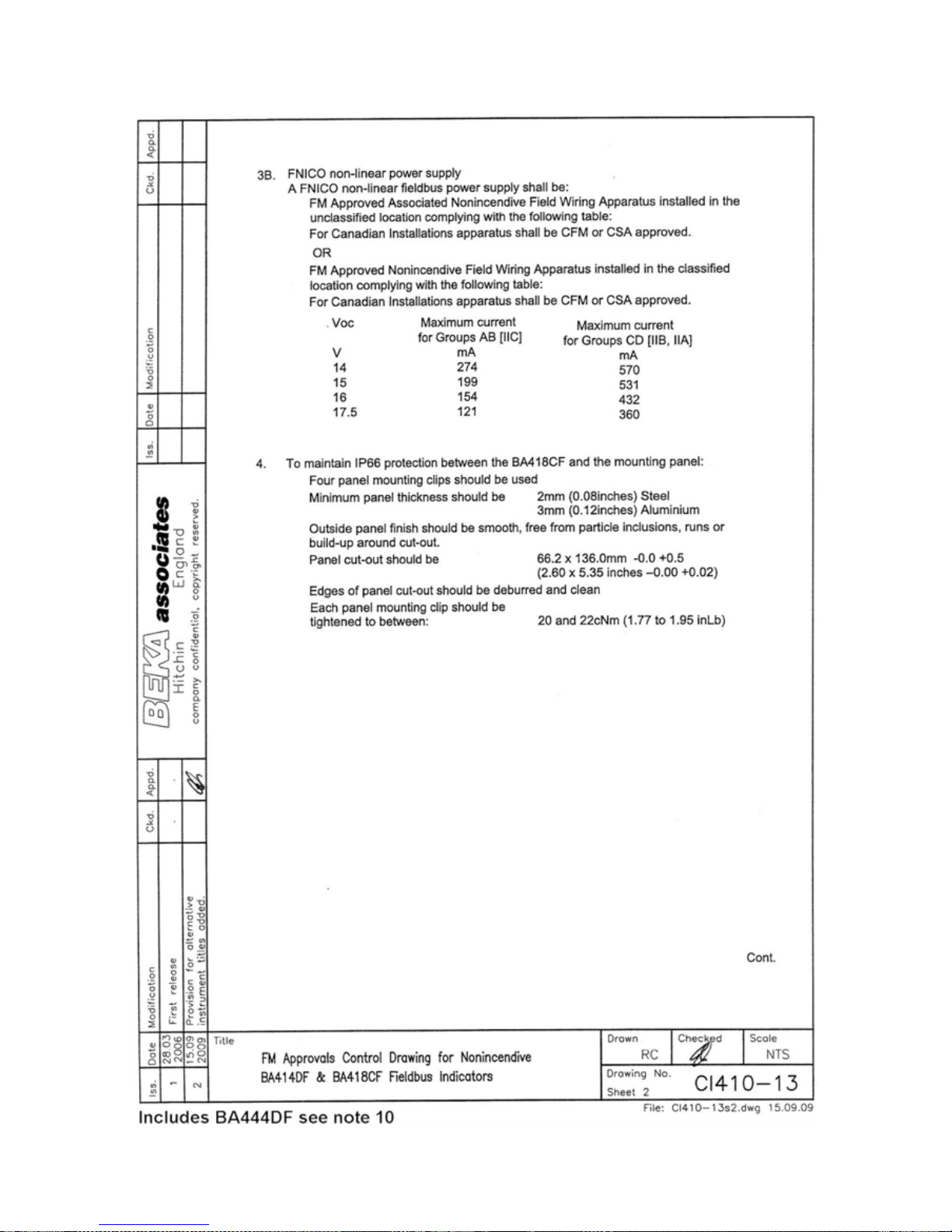
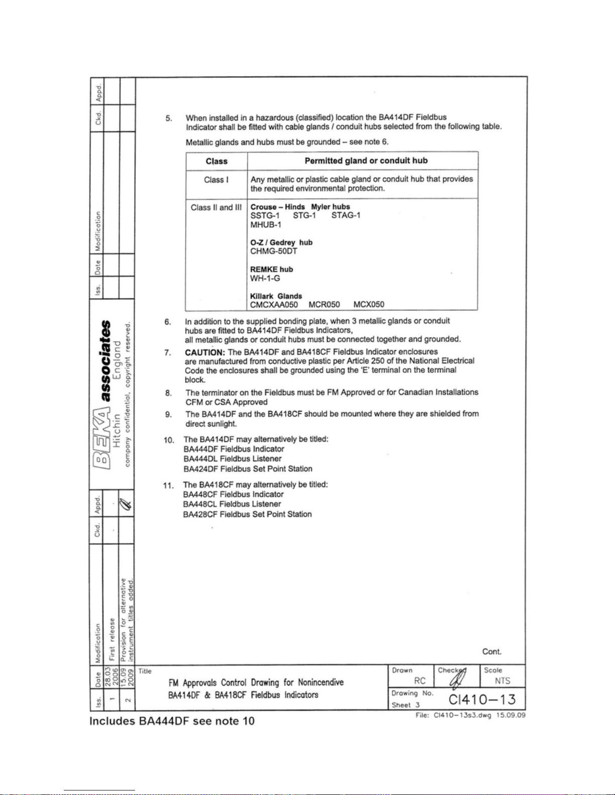
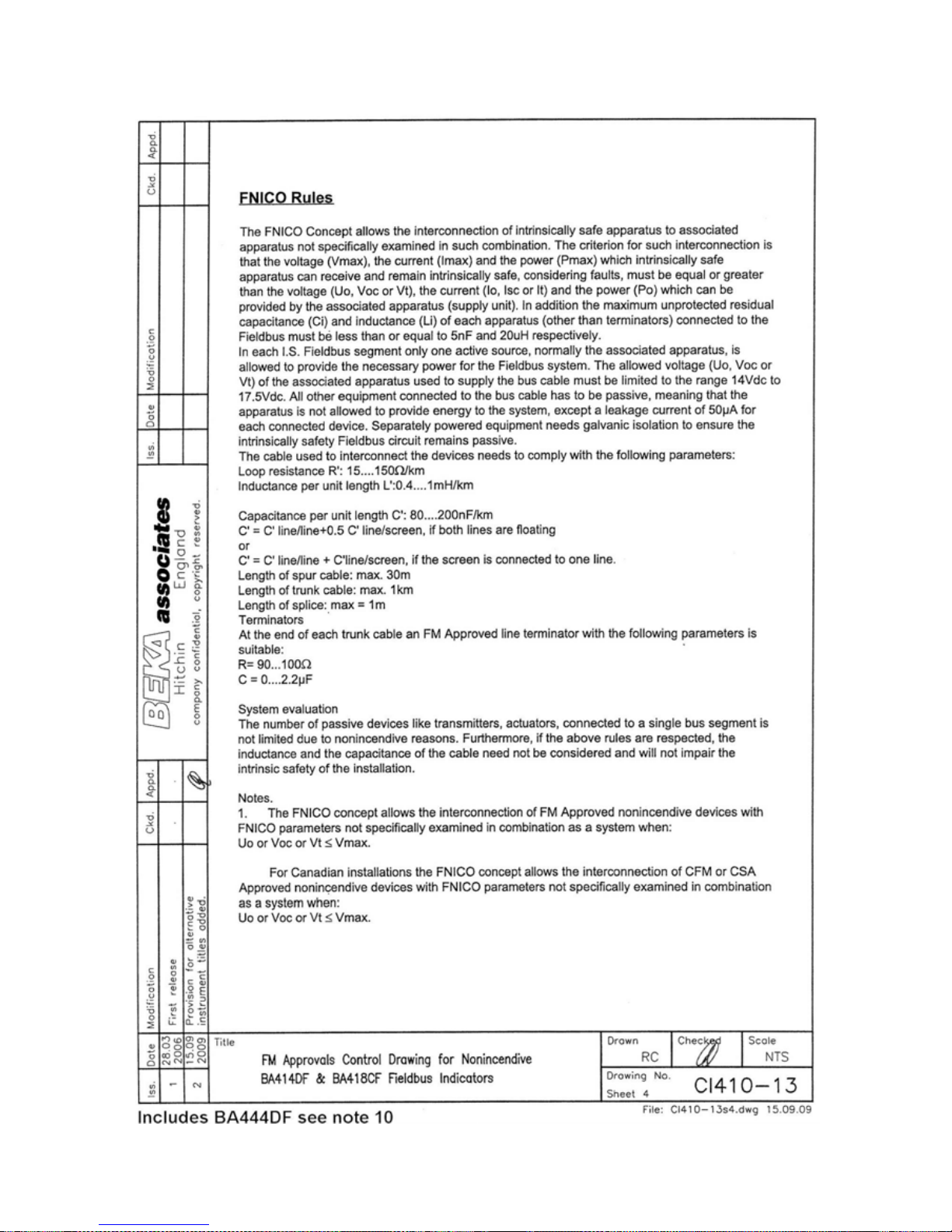
The BA448CF-F is FM Class 3611 nonincendive
approved allowing it to be installed in Division 2
hazardous (classified) locations without the need
for Zener barriers or galvanic isolators. US
installations must comply with the BEKA
associates Control Drawing CI410-13, which is
attached to this Appendix, and with the National
Electrical Code ANSI/NFPA70.
Canadian nonincendive installations must comply
with the Canadian Electrical Code C22.2 and with
BEKA associates Control Drawing CI410-13, which
is attached to this Appendix.
The FM and cFM Nonincendive Approvals also
allow the BA448CF-F fieldbus indicator to be
connected to any appropriately certified FNICO
compliant fieldbus segment.
The BA448CF-F has a T4 rating at ambient
temperatures up to +70ºC and may be used with
the following gases:
Nonincendive
Division 2
Class I Group A & B
Group C
Group D
Zone 2
Class I Group IIC
Group IIB
Group IIA
Page 17
17
Page 18
18
Page 19
19
Page 20
20
Page 21
21
Page 22
22
Page 23
23
Page 24

24
APPENDIX 2
IECEx Certification
A2.0 The IECEx Certification Scheme
IECEx is a global certification scheme for
explosion protected products which aims to
harmonise international certification standards.
For additional information about the IECEx
certification scheme and to view the BEKA
associate certificates, please visit www.iecex.com
A2.1 IECEx Certificate of Conformity
The BA448CF-F Fieldbus Indicator has been
issued with an IECEx Certificate of Conformity
number IECEx ITS 06.0013X which specifies the
following certification codes and marking:
Ex ia IIC T4 Ga
FISCO Field Device Ex ia IIC T4
Ta = -40oC to 70 oC
See below for details of safe use in Zone 0.
CAUTION
Installation in Zone 0
When installed in a Zone 0 potentially
explosive atmosphere, the indicator shall be
installed such that even in the event of rare
incidents, an ignition source due to impact
or friction between the aluminium enclosure
at the rear of the instrument mounting panel
and iron/steel is excluded.
When connected to an IECEx certified system the
BA448CF-F may be installed in:
Zone 0 explosive gas air mixture
continuously present.
Note: Special conditions for
safe use apply see above.
Zone 1 explosive gas air mixture
likely to occur in normal
operation.
Zone 2 explosive gas air mixture not
likely to occur, and if it does will
only exist for a short time.
Be used with gases in groups:
Group A propane
Group B ethylene
Group C hydrogen
Having a temperature classification of:
T1 450oC
T2 300oC
T3 200oC
T4 135oC
At an ambient temperature between –40 and
+70oC.
Note: the guaranteed operating temperature range
of the BA448C Fieldbus Indicator is –20 to +70oC
The IECEx safety parameters are identical to the
ATEX parameters and, like the ATEX certification,
confirm that the BA448CF-F complies with the
FISCO Field Device requirements specified in
IEC60079-27.
The IECEx certificate may be downloaded from
www.beka.co.uk, www.iecex.com or requested
from the BEKA sales office.
A2.2 Installation
The BA448CF-F IECEx and ATEX certifications
have identical intrinsic safety parameters and
installation requirements. The ATEX system
design requirements described in section 4 of this
manual may therefore be used for IECEx
installations, but the local code of practice should
always be consulted.
 Loading...