

Page 1
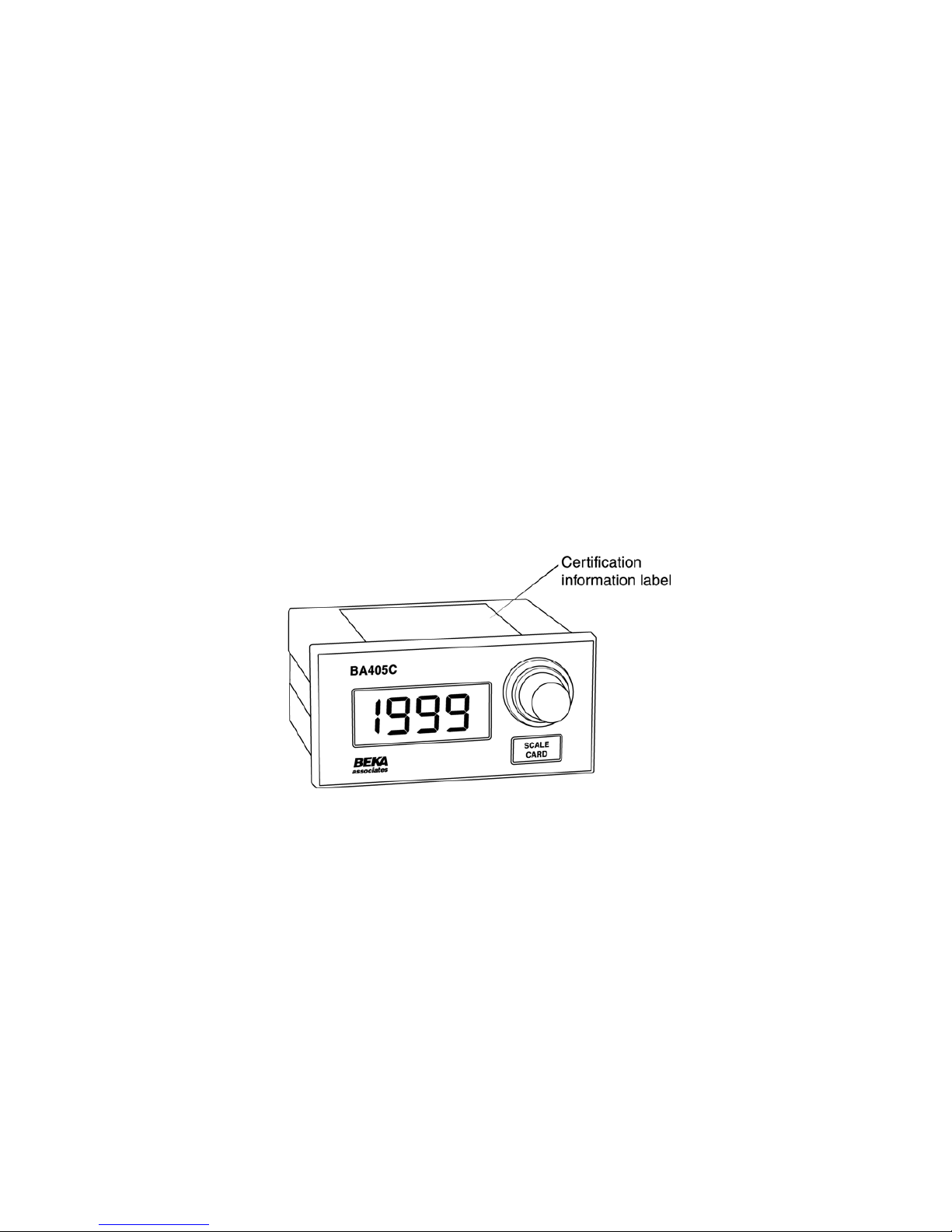
BA405C
intrinsically safe
2-wire 4/20mA
manual set point
station
issue 6
Issue: 6
17
th
November 2009
Page 2

2
1. Description
2. Operation
3. Intrinsic Safety Certification
3.1 ATEX certificate
3.2 FM Approval for use in the USA
3.3 Safety parameters
3.4 Zones, gas groups & T rating
3.5 Certification label information
4. System Design for Hazardous Areas
4.1 4/20mA loop using Zener barriers
4.2 4/20mA loop using Galvanic
Isolators.
4.3 Optional backlights
4.3.1 Separately powered backlight
4.3.2 Loop powered backlight
5. Installation
5.1 Location
5.2 Installation procedure
5.3 EMC
6. Calibration
6.1 Internal display
6.1.1 Zero adjustment
6.1.2 Span adjustment
6.1.3 Decimal point
6.1.4 Reverse action
6.1.5 Calibration example
6.1.6 Over & under-range
7. Maintenance
7.1 Fault finding during commissioning
7.2 Fault finding after commissioning
7.3 Servicing
7.4 Routine maintenance
7.5 Guarantee
7.6 Customer comments
8. Accessories
8.1 Scale card.
8.2 Tag strip
Appendix 1
FM Approval for use in the USA
The BA405C is CE marked to show compliance with the
European Explosive Atmospheres Directive 94/9/EC
and the European EMC Directive 2004/108/EC
CONTENTS
Page 3
3
1. DESCRIPTION
The BA405C is an intrinsically safe loop powered
set point station which enables the current flowing
in a 4/20mA loop to be manually adjusted from
within a hazardous process area.
The main application of the BA405C is the
adjustment of plant parameters. Controller set
points, actuator positions or any variable
represented by a 4/20mA signal may be manually
adjusted.
The BA405C has a high resolution ten turn control
allowing accurate adjustment of the 4/20mA
current and a 3½ digit indicator to display the
4/20mA loop current in any linear engineering
units. Optional separately powered and loop
powered display backlights are available for the
display.
The BA405C and the optional display backlights
comply with the European ATEX Directive 94/9/EC
and have been issued with an EC-Type
Examination certificate by Notified Body ITS
Testing and Certification Ltd.
For use in the USA the BA405C has intrinsic safety
and nonincendive FM Approval - see Appendix 1.
2. OPERATION
This instruction manual describes ATEX system
design and installation, please refer to Appendix 1
for details of the FM Approval.
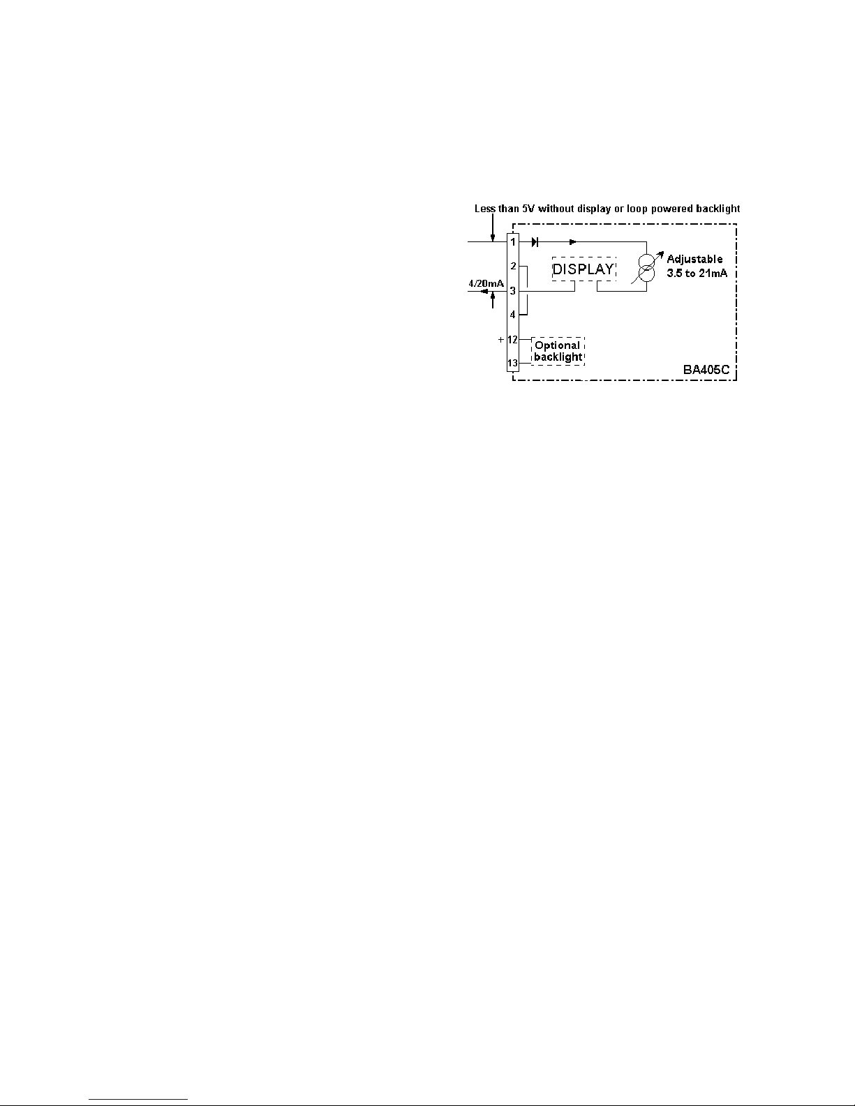
Fig 1 shows a simplified block diagram of the
BA405C manual set point station. The ten turn
control knob enables the current flowing in the loop
to be manually set at any value between
approximately 3.5 and 21mA. The output
resistance of the BA405C is very high so the loop
current will be unaffected by changes in the supply
voltage.
Caution
The 4/20mA output should not be used for
critical safety applications.
The 3½ digit internal indicator can easily be
calibrated on-site to show the loop current in
engineering units. For example, in an application
where the BA405C is being used to adjust the set
point of a speed controller, the internal indicator
may be calibrated to display the requested speed
in
RPM.
Two types of optional display backlighting are
available. The loop powered backlight produces
green background illumination enabling the display
to be read at night or in poor lighting conditions.
The separately powered backlight has a bright
orange output which enhances daylight viewing.
Fig 1 Simplified block diagram of BA405C
3. INTRINSIC SAFETY CERTIFICATION
3.1 ATEX certificate
The BA405C has been issued with an EC-Type
Examination Certificate ITS03ATEX21103 by
Notified Body Intertek Testing Services (ITS)
confirming compliance with the European ATEX
Directive 94/9/EC for Group II, Category 1 G
apparatus, EEx ia IIC T5. The instrument bears
the Community Mark and, subject to local codes of
practice, may be installed in any of the European
Economic Area (EEA) member countries. ATEX
certificates are also acceptable for installations in
Switzerland. This manual describes installations
which conform with BS EN60079:Part14 Electrical
Installation in Hazardous Areas. When designing
systems for installation outside the UK, the local
Code of Practice should be consulted.
3.2 FM Approval for use in the USA
Please refer to Appendix 1 for information about
FM intrinsic safety and nonincendive approval of
the BA405C
.
Page 4

4
3.3 Safety parameters
The BA405C EC-Type Examination Certificate
specifies the maximum input safety parameters for
the two 4/20mA terminals 1 and 3, and the
equivalent internal capacitance and inductance
that appears between the terminals. Using the
entity concept and these safety parameters,
suitable Zener barriers or galvanic isolators may
be selected and the maximum permissable cable
parameters calculated.
The following figures are reproduced from the
ATEX certificate ITS03ATEX21103
Terminals 1 and 3:
(4/20mA output terminals)
Basic BA405C set point station without
optional loop powered display backlight.
Maximum input safety parameters
Ui = 30V dc
Ii = 200mA dc
Pi = 0.85W
Equivalent capacitance and inductance
Ci = 40nF
Li = 0.01mH
With loop powered display backlight
Terminals 1 and 13
(3 and 12 connected in series)
Maximum input safety parameters
Ui = 30V dc
Ii = 200mA dc
Pi = 0.85W
Equivalent capacitance and inductance
Ci = 40nF
Li = 0.03mH
Separately powered display backlight
Terminals 12 and 13
Maximum input safety parameters
Ui = 28V dc
Ii = 159mA dc
Pi = 0.8W
Equivalent capacitance and inductance
Ci = 30nF
Li = 0.01mH
3.4 Zones, Gas Groups and T rating
The BA405C and both the optional display
backlights have been certified as Group II category
1G apparatus, EEx ia IIC T5. When powered via
a compatable Zener barrier or galvanic isolator the
BA405C manual set point station may be installed
in:
Zone 0 explosive gas air mixture
continuously present.
Zone 1 explosive gas air mixture likely
to occur in normal operation.
Zone 2 explosive gas air mixture not
likely to occur, and if it does will
only exist for a short time.
Be used with gases in groups:
Group A propane
Group B ethylene
Group C hydrogen
Having a temperature classification of:
T1 450°C
T2 300°C
T3 200°C
T4 135°C
T5 100°C
WARNING installation in Zone 0
When installed in a Zone 0 potentially
explosive atmosphere requiring apparatus
of Category 1G, the set point station shall be
installed such that even in the event of rare
incidents, an ignition source due to impact
or friction between the aluminium enclosure
at the rear of the instrument mounting panel
and iron/steel is excluded.
3.5 Certification label information
The ATEX certification information is shown on a
label fitted in a recess on the top outer surface of
the enclosure.
BA405C ATEX certification label
Page 5
5
4. SYSTEM DESIGN FOR HAZARDOUS
AREAS
4.1 4/20mA loop using Zener barriers
The required operating voltage depends on which
options are fitted as shown below.
Options Voltage range Terminals
BA405C 6.1 to 30V 1 & 3
Without
Options.
BA405C with 10 to 30V 1 & 13
Loop powered (3 & 12
display joined
backlight. together)
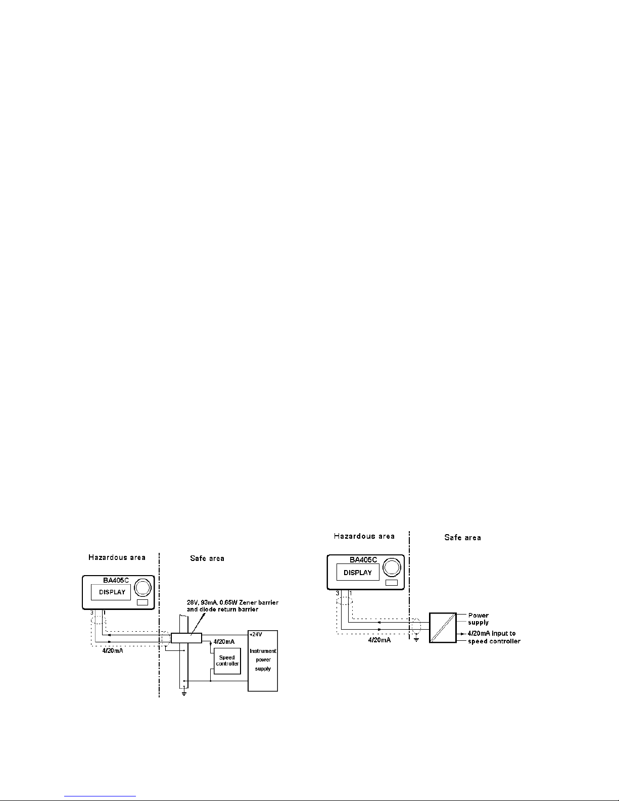
Fig 2 illustrates a typical application in which a
BA405C is being used to adjust the septpoint of a
speed controller. To enable the negative side of
both the load and the power supply to be earthed,
a Zener barrier is required in series with both wires
going into the hazardous area.
Any Zener barrier or barriers certified by an EEC
approved body to EEx ia IIC, having output
parameters equal to or less than the maximum
BA405C certified input safety parameters may be
used. For this type of application a 28V, 93mA
0.65W (28V 300Ω) device is normally used to
power the loop, plus a diode return barrier. These
two devices are available as two channels in one
package.
The maximum permitted cable parameters are
those specified on the Zener barrier certificate less
the set point stations equivalent input capacitance
or inductance Ci & Li.
When designing the loop it is necessary to
establish that the maximum voltage drop caused
by the manual set point station, both Zener
barriers, the load and cable resistance is always
less than the minimum supply voltage.
Fig 2 Typical application using barriers
In this example:
Minimum operating voltage of BA405C 6.1V
Maximum voltage drop caused by 28V 6.8V
93mA, 0.65W Zener barrier
(340Ω end-to- end resistance x 20mA)
Maximum voltage drop caused by 1.3V
diode return barrier
Maximum voltage drop caused by 5.0V
250ohm load
(250ohms x 20mA)
Maximum voltage drop caused by 0.2V
Cable resistance
(10ohms x 20mA)
______
Total maximum voltage drop 19.4V
The power supply voltage must therefore be above
19.4V, but below 25.5V which is the maximum
working voltage of a typical 28V Zener barrier. If
the optional loop powered backlight was included
in the circuit this introduces a further 3.9V drop so
that the supply voltage would have to be regulated
between 23.3 and 25.5 See section 4.3.2.
4.2 4/20mA loop using Galvanic Isolators
Galvanic isolators, although more expensive than
Zener barriers, do not require a high integrity earth
connection. For small systems where a high
integrity earth is not already available, the use of
galvanic isolators often reduces the overall
installation cost.
The example described in section 4.1 can be
simplified by the use of galvanic isolators as shown
in Fig 3.
Fig 3 Typical application using a galvanic isolator
Page 6
6
Any galvanic isolator certified EEx ia IIC by an
EEC approved body with output parameters equal
to or less than the maximum BA405C certified
input parameters may be used.
The maximum permitted cable parameters for the
loop should be calculated by subtracting Ci & Li for
the BA405C from the cable parameters specified
on the galvanic isolator certificate.
When designing the loop it is necessary to
establish that the supply voltage between terminals
1 & 3 of the BA405C set point station always
exceeds the minimum operating voltage shown in
section 4.1
4.3 Optional Backlights
The BA405C set point station can be supplied with
two different backlights. The loop powered
backlight produces green background illumination
enabling the display to be read at night or in poor
lighting conditions. No additional power supply, IS
interface or field wiring are required, but the
minimum operating voltage drop of the set point
station is increased to 11.1V.
Alternatively, the separately powered backlight has
a bright orange output which enhances daylight
viewing, but it requires an additional IS interface
and field wiring.
4.3.1 Separately powered backlight
This backlight is segregated from the measuring
circuit and has been certified as a separate
intrinsically safe circuit.
The maximum input safety parameters are
Maximum input
Ui = 28V dc
Ii = 159mA dc
Pi = 0.8W
Equivalent capacitance and inductance
Ci = 30nF
Li = 0.01mH
Any Zener barrier or isolator certified EEx ia IIC by
an EEC approved body which has output
parameters equal to, or less than, the maximum
input parameters specified above may be used.
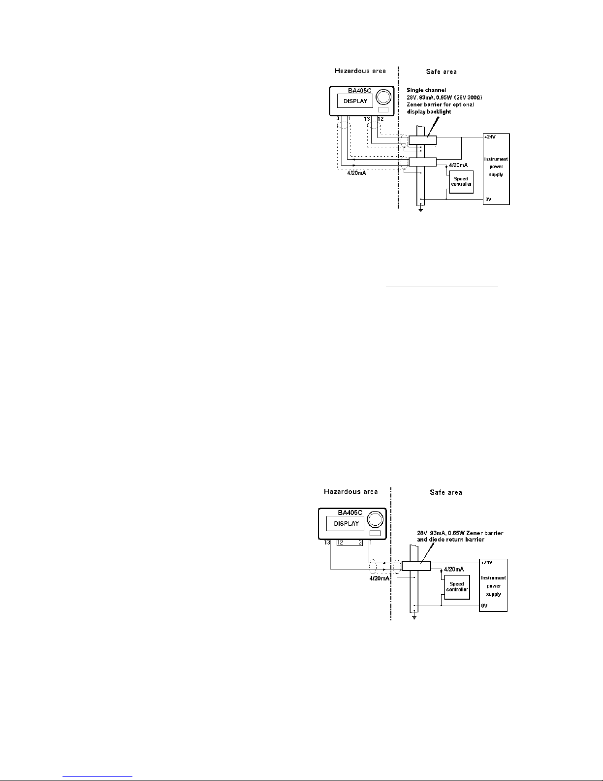
Most installations would use a 28V, 93mA 0.65W
(28V 300Ω) device as shown in Fig 4.
The display brilliance depends upon the current
flowing through the backlight which is determined
by the supply voltage and the end-to-end
resistance of the Zener barrier or output resistance
of the galvanic isolator. Brilliance will not be
significantly reduced until the current falls below
20mA.
Fig 4 Separately powered backlight
The separately powered backlight requires a
minimum supply voltage of 14V, The backlight
current can be calculated from:
Backlight current = Vsupply –14
End-to-end resistance of barrier#
# Or output resistance of galvanic isolator
Two BA405C separately powered backlights may
be powered in parallel from a single 28V 300Ω
Zener barrier or galvanic isolator, but the display
brilliance will be reduced.
4.3.2 Loop powered backlight
The loop powered backlight is connected in series
with, and powered by, the 4/20mA current from the
set point station This eliminates the need for a
separate Zener barrier or galvanic isolator and for
additional wiring, thus significantly reducing the
installation cost.
Fig 5 Loop powered backlight
Fig 5 shows how the loop powered backlight
should be connected in series with the set point
station. Any Zener barrier or galvanic isolator
certified EEx ia IIC by an EEC approved
certification body may be used providing the output
safety parameters do not exceed:
Page 7
7
Uo = 30V dc
Io = 159mA
Po = 0.8W
The maximum permitted cable parameters for the
loop should be calculated by subtracting Ci & Li for
the BA405C with a loop powered backlight from
the cable parameters specified on the Zener
barrier or galvanic isolator certificate.
Inclusion of the loop powered backlight increases
the minimum operating voltage of the BA405C to
10V
5. INSTALLATION
5.1 Location
The BA405C is housed in a robust aluminium
enclosure with a polyester front panel and a Noryl
bezel. The front panel provides IP65 protection
and a gasket seals the joint between the
instrument and the panel. The BA405C may be
installed in any panel providing the environmental
limits shown in the specification are not exceeded.
The front of the instrument should not be cleaned
with, or exposed to solvents.
Please refer to BEKA associates if high vibration is
anticipated.
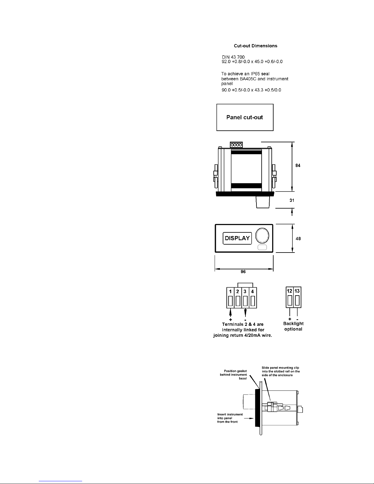
Fig 6 shows the enclosure dimensions and the
recommended panel cut-out sizes.
5.2 Installation Procedure
a. Insert the BA405C set point station into the
panel aperture from the front. Ensure that
the gasket is correctly positioned under the
bezel.
b. Fix two panel mounting clips to opposite
sides of the instrument and tighten until the
indicator is secured as shown in Fig 7.
c. Connect the panel wiring to the rear terminal
block as shown in Fig 6. To simplify
installation, the terminals are removable so
that the panel wiring can be completed
before the instrument is installed.
5.3 EMC
The BA405C complies with the requirements of the
European EMC Directive. For specified immunity
all wiring should be in screened twisted pairs with
the screen earthed within the safe area. The
enclosure may be earthed locally by securing a tag
under one of the rear panel corner fixing screws,
Fig 6 BA405C Dimensions
Fig 7 Fitting panel mounting clips
Page 8
8
6. CALIBRATION
The BA405C output currrent does not require any
calibration, the front panel multi-turn control will
always adjust the output current between
approximately 3.5 and 21mA.
6.1 Internal display
The internal display requires calibrating so that the
4/20mA loop current is shown in the required
engineering units.
The BA405C will be supplied with the display
calibrated as requested at time of ordering. If
calibration is not requested, the display will be set
to show 00.0 with 4.000mA loop current and 100.0
with 20.000mA loop current.
The display is calibrated by plug-in links and two
multi-turn potentiometers which are accessible
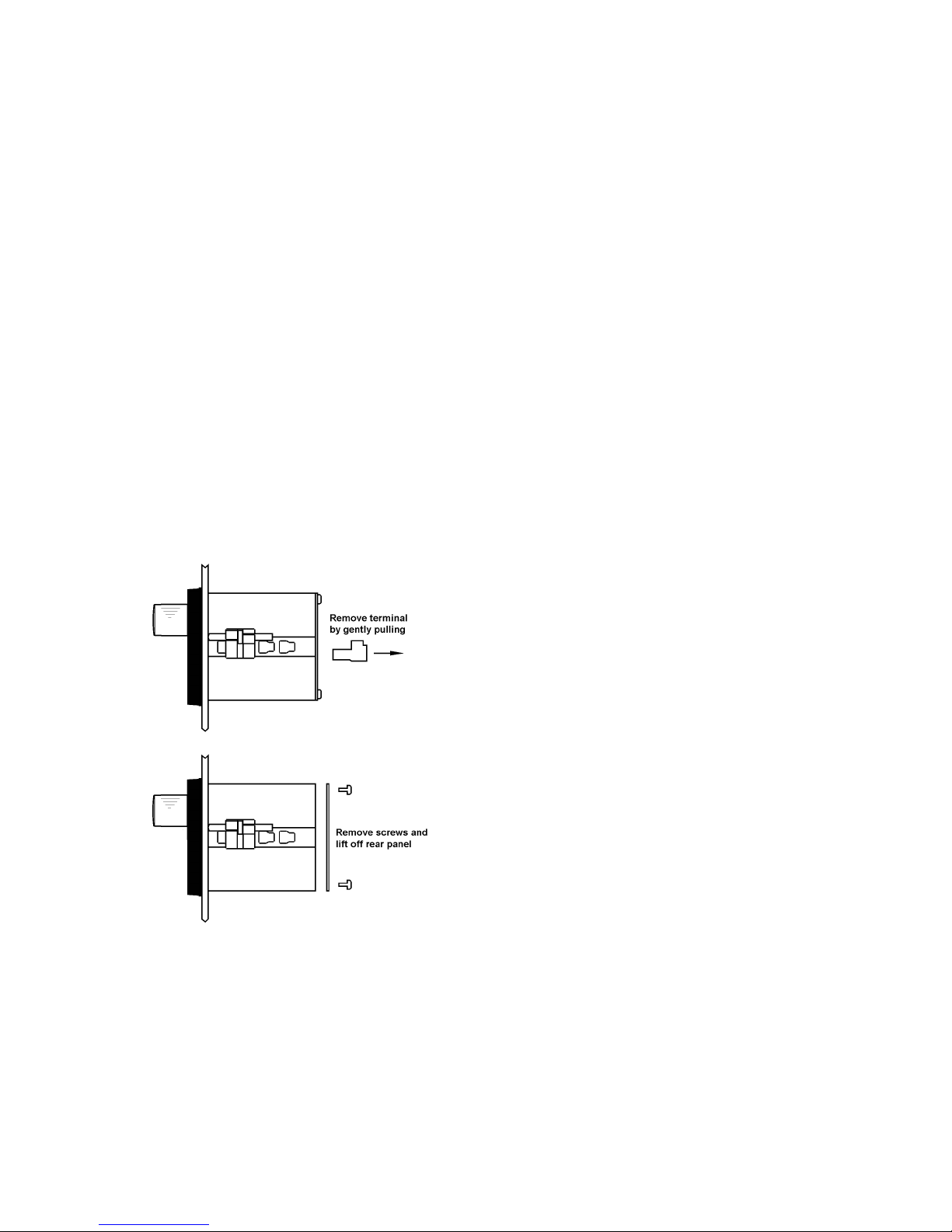
through holes in the rear panel. To
gain access to the links the rear panel must be
removed as shown in Fig 8.
For maximum accuracy the display should be
calibrated using a traceable current measuring
device with an accuracy greater than 4µA.
Fig 8 Removal of rear panel
6.1.1 Zero adjustment
Zero is defined as the number displayed when the
BA405C output is 4.000mA, and may adjusted
between -1000 and 1000. The zero
potentiometer has two ranges 0 to 500 and 500 to
1000. Tthe polarity of the zero is defined by the
position of the suppression / elevation links.
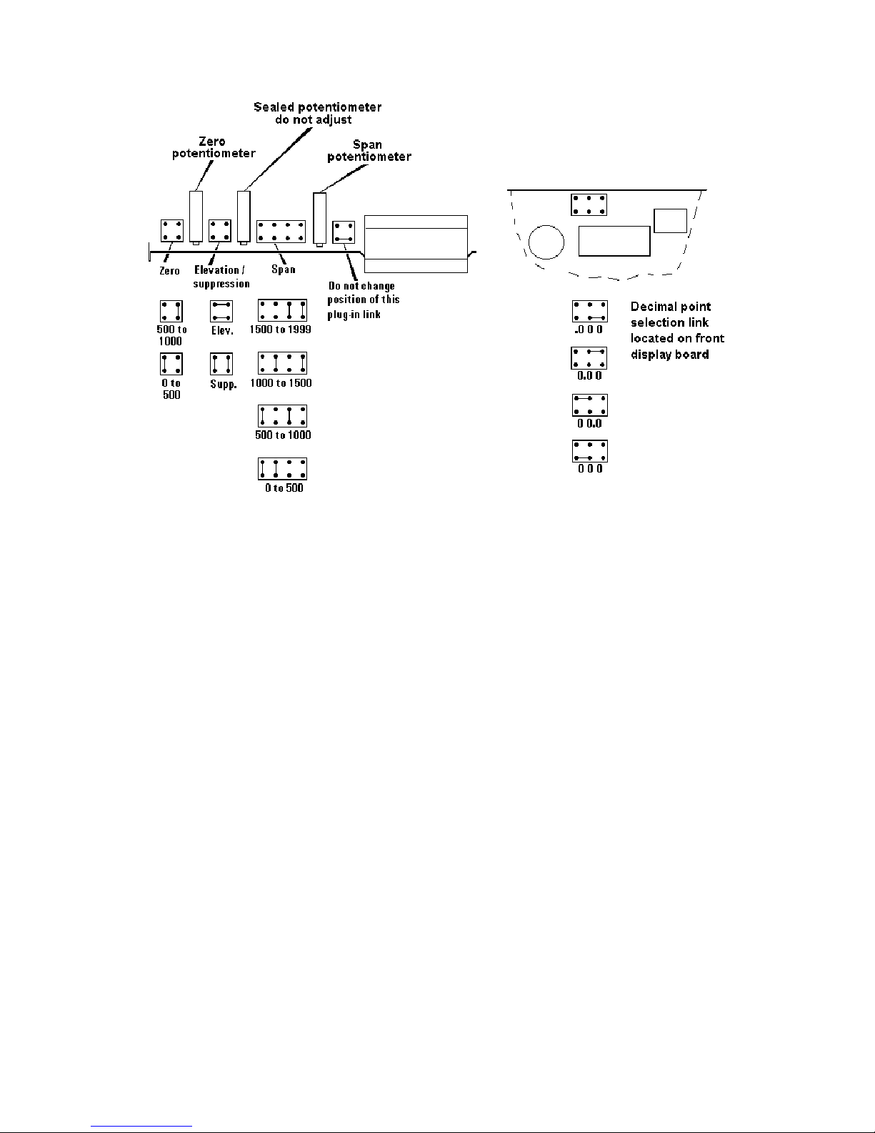
Fig 9 shows the position of the zero links and zero
potentiometer.
Suppression / elevation links
Elevation Positive zero 0 to 1000
or Suppression Negative zero 0 to -1000
Zero link
0 to 500
or 500 to 1000
6..1.2 Span adjustment
Span is defined as the difference between the
number displayed at 4.000mA and the number
displayed at 20.000mA output. The span
potentiometer has four ranges defined by the span
links, and may be adjusted to any number between
0 and 1999.
Fig 9 shows the position of the span links and span
potentiometer.
Span links
000 to 500
or 500 to 1000
or 1000 to 1500
or 1500 to 1999
6.1.3 Decimal point
A dummy decimal point may be displayed between
any of the four digits. The position or absence of
this decimal point is determined by
the position of the decimal point link shown in Fig
9. When calculating the required span and zero
setting the decimal point should be ignored.
6.1.4 Reverse action
Normally the BA405C display increases as the
loop current increases, but this can be reversed.
Please contact BEKA associates for details.
Page 9
9
6.1.5 Calibration example
A BA405C set point station is required to display
25.0 with a 4.000mA output and 115.0 with at
20.000mA output.
i.e. A zero of positive 250 Ignoring decimal
point.
A span of 900
A dummy decimal point in position 00.0
The following adjustments are required:
Step 1 The BA405C is required to display a
positive zero therefore the
suppression / elevation links should be
put in the elevation position.
Step 2 The required zero is 250, therefore the
zero link should be put in the 0 to 500
position.
Step 3 The required span is 900, therefore the
span links should be placed in the 500 to
1000 position.
Step 4 A dummy decimal point is required
between the least two significant digits,
therefore the decimal point link should be
placed in the 00.0 position.
Step 5 Adjust the BA405C front panel control
until the output current measured by
external ammeter is 4.000mA. The zero
potentiometer at the rear of the BA405C
should then be adjusted until the
BA405C displays 25.0
Step 6 Adjust the BA405C front panel control
until the external current measured by an
external ammeter is 20.000mA. The
span potentiometer at the rear of the
BA405C should then be adjusted until
the BA405C displays 115.0
Step 7 Repeat steps 5 and 6 until both
calibration points are correct. The span
and zero controls are almost
independent so it should only be
necessary to repeat each adjustment
twice.
Fig 9 Position of calibration plug-in links and potentiometers
Page 10

10
6.1.6 Over and under-range
The BA405C can display numbers between 1999 and 1999. If this range is exceeded the three
least significant digits will be blanked. Underrange is indicated by -1 and over-range by 1.
7. MAINTENANCE
7.1 Fault finding during commissioning
If a BA405C set point station fails to function
during commissioning the following procedure
should be followed:
Symptom Cause Solution
No loop Incorrect Check wiring
current wiring or no and power
power supply supply polarity
BA405C Positive The display has been
displays 1 over-range incorrectly calibrated
& is trying to show a
number greater than
1999.
BA405C Negative The display has been
displays -1 over-range incorrectly calibrated
& is trying to show a
number less than
-1999.
Unstable Insufficient Check that voltage
loop supply between terminals
current voltage 1 & 3 is greater than
6.1V, or 10V between
terminals 1 & 13 if a
loop powered
backlight is fitted.
Unstable Power supply Reduce ripple
display has voltage.
ripple
7.2 Fault finding after commissioning
ENSURE PLANT SAFETY BEFORE
STARTING MAINTENANCE
Live maintenance is permitted on intrinsically
safe equipment installed in a hazardous area,
but only certified test equipment should be
used unless a gas clearance certificate is
available.
If a BA405C fails after it has been functioning
correctly, the following procedure should be
followed:
Symptom Cause Solution
No loop Wiring or power Check wiring
current supply fault and power
supply
Unstable Insufficient Check that voltage
loop supply between terminals
current voltage 1 & 3 is greater than
6.1, or 10V between
terminals 1 & 13 if fitted
with a loop powered
backlight.
Unstable Power supply Reduce ripple
display has developed
voltage ripple
If this procedure does not reveal the cause of the
fault, it is recommended that the BA405C manual
set point station is replaced with a spare
instrument.
7.3 Servicing
We recommend that faulty BA405C set point
stations are returned to BEKA associates or to our
local agent for repair.
7.4 Routine maintenence
The mechanical and electrical condition of the
instrument should be regularly checked. Initially
annual inspections are recommended, but the
inspection frequency should be adjusted to suit the
environmental conditions.
7.5 Guarantee
Set point stations which fail within the guarantee
period should be returned to BEKA associates or
our local agent. It is helpful if a brief description of
the fault symptoms is provided.
7.6 Customer comments
BEKA associates is always pleased to receive
comments from customers about our products and
services. All communications are acknowledged
and whenever possible, suggestions are
implemented.
Page 11

11
8. ACCESSORIES
8.1 Scale card
The BA405C has a window below the control knob
to accommodate a scale card. Set point stations
can be supplied with a printed scale card showing
any units specified at the time of ordering e.g.
o
C,
mBar, RPM. If a printed scale card is not
requested, a blank card will be supplied.
Scale cards can easily be marked on site as
follows:
a. Remove the rear terminal block(s) and the
rear panel as shown in Fig 8.
b. Remove the end cap from the front panel
control knob using a thin bladed screwdriver.
This will reveal a screw collet which secures
the control knob to the shaft. Loosen the
collet by turning the brass split screwhead anti
clockwise and then carefully pull the control
knob from the shaft.
c. Pull the electronic assembly from the rear of
the enclosure.
d. Remove the blank scale card(s) and mark
with the required legend. Replace scale
card(s) taking care to align them within the
front panel window.
e. Slide the electronic assembly into the rear of
the enclosure and carefully guide the control
shaft through the front panel seal. Replace
the rear panel and terminals.
f. Replace the control knob and tighten the
collet screw. Finally push the knob end cap
into place.
8.2 Tag strip
The BA405C can be supplied with a thermally
printed tag strip on the rear panel. This tag strip is
not visible from the front of the instrument after
installation.
Page 12

12
APPENDIX 1
FM Approval for use in the USA
A1.0 Factory Mutual Approval
For installation in the USA the BA405C has FM
Intrinsic Safety and FM Nonincendive approval,
project identification 3026081. Copies of the
Certificate of Compliance are available from BEKA
associates sales office and www.beka.co.uk.
A2.1 Intrinsic safety approval
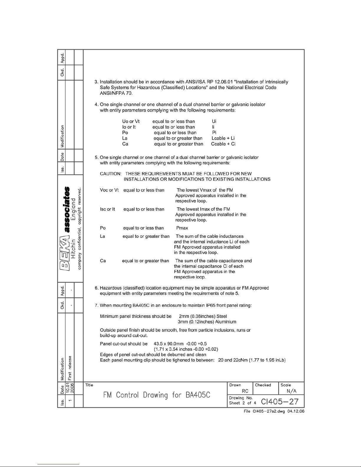
The BA405C is approved to the FM Class 3610
intrinsic safety standard for use in indoor and
outdoor hazardous (classified) locations.
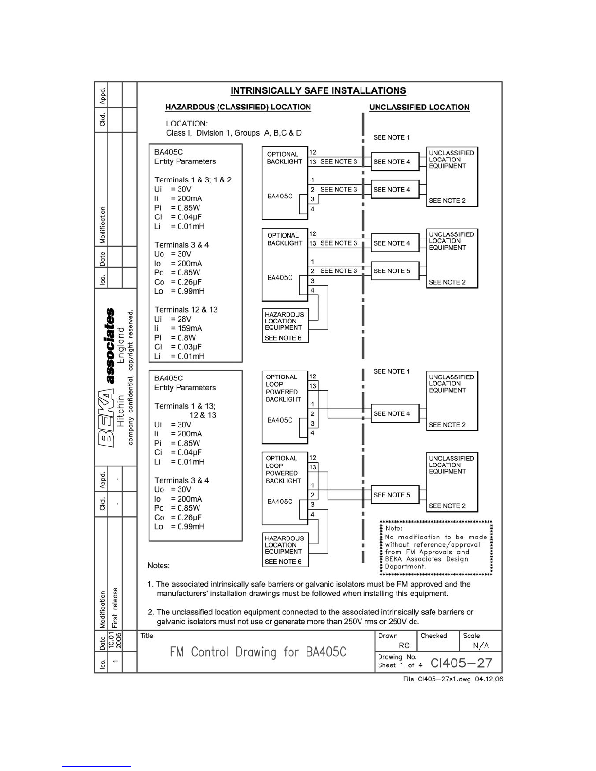
Installations must comply with BEKA associates
Control Drawing CI405-27 which is attached to this
Appendix, ANSI/ISA RP12.06.01 ‘Installation of
Intrinsically safe Systems for Hazardous
(Classified) Locations’ and with the National
El;ectrical Code ANSI/NFPA70.
The BA405C has a T4 rating at ambient
temperatures up to 60
o
C and may be used with
the following gases:
Intrinsic Safety
Division 1 or 2
Class I Group A & B
Group C
Group D
Zone 0, 1 or 2
Class 1 Group IIC
Group IIB
Group IIA
The FM entity parameters are similar to the ATEX
parameters. The intrinsically safe systems shown
in this manual may therefore be used for
installations in the USA providing the Zener
barriers or galvanic isolators are FM Approved. All
installations must comply with BEKA associates
Control Drawing CI405-27.
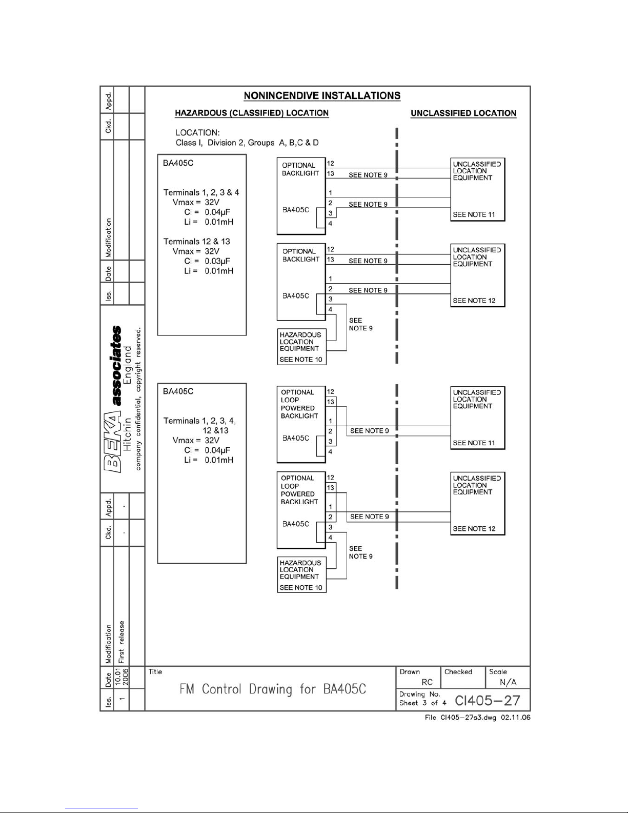
A2.2 Nonincendive approval
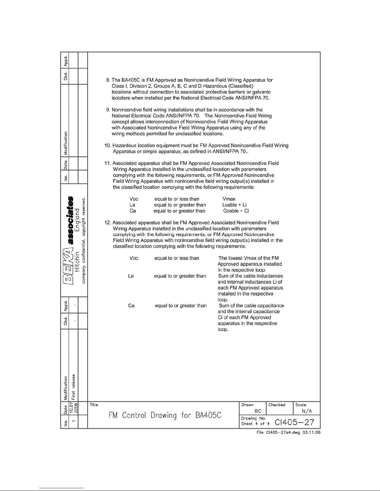
The BA405C is FM Class 3611 nonincendive
approved allowing it to be installed in Division 2
indoor and outdoor hazardous (classified)
locations without the need for Zener barriers or
galvanic isolators. US installations must comply
with the BEKA associates Control Drawing CI40527, which is attached to this Appendix, and with
the National Electrical Code ANSI/NFPA70.
The BA414DF has a T4 rating at ambient
temperatures up to +60
o
C and may be used with
the following gases:
Nonincendive
Division 2
Class I Group A & B
Group C
Group D
Zone 2
Class I Group IIC
Group IIB
Group IIA
Page 13
13
Page 14
14
Page 15
15
Page 16
16
 Loading...