

Page 1
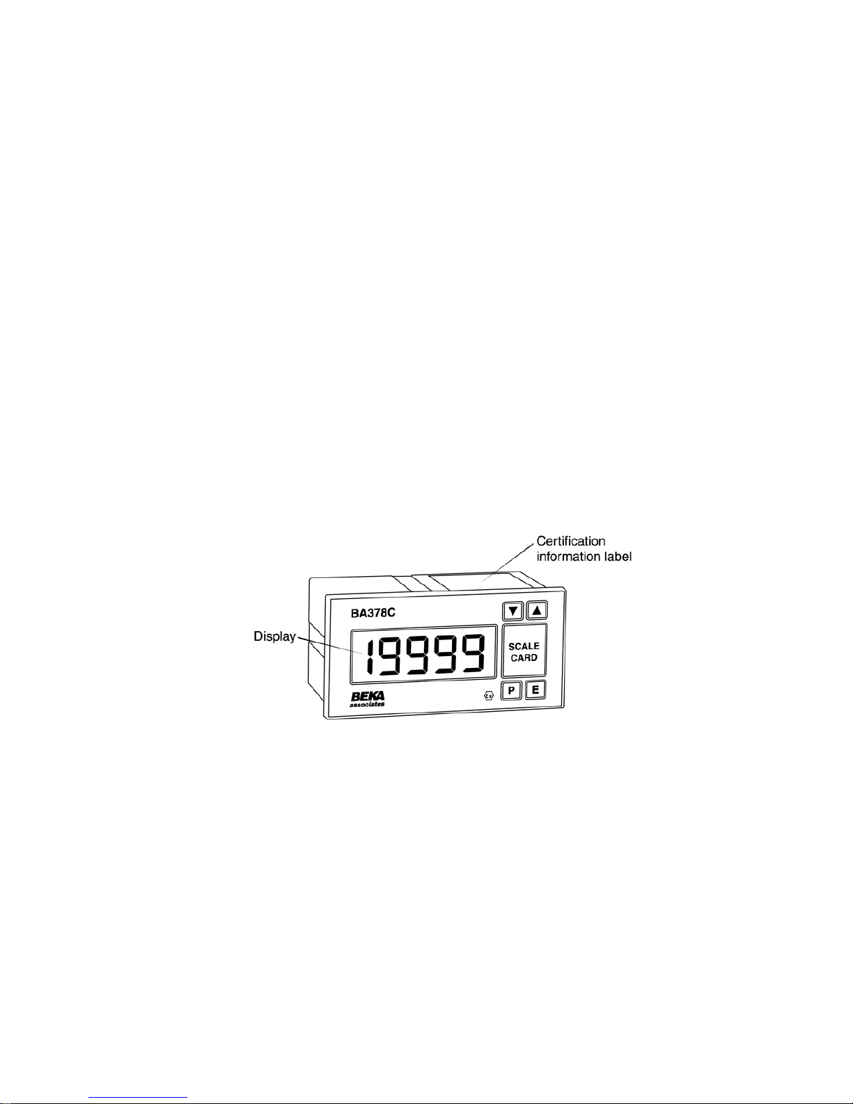
BA378C
Intrinsically safe
panel mounting
indicating temperature
transmitter
issue 6
Issue: 6
25th September 2008
Page 2

1. Description
2. Operation
2.1 Controls
3. Intrinsic Safety Certification
3.1 ATEX certificate
3.2 Other intrinsic safety certifications
3.3 Zones, Gas Groups and T rating
3.4 Certification information label
3.5 Input terminals 1, 2, 3 & 4
3.6 4/20mA output - Terminals 5 & 6
4. Electrical System Design for
Installations in Hazardous Areas
4.1 Using Zener barriers
4.2 Using galvanic isolators
5. Installation
5.1 Location
5.2 Installation procedure
5.3 EMC
6. Programming and calibration
6.1 Summary of Programme Menu
functions.
6.2 Description of Programme Menu
functions.
6.2.1 Transmitter input
6.3 For thermocouple inputs
6.3.1 Types of thermocouple
6.3.2 Display units
6.3.3 Display resolution
6.3.4 Cold junction compensation
6.3.5 Input open circuit drive
6.4 For resistance thermometer inputs
6.4.1 Type of resistance thermometer
6.4.2 Display units
6.4.3 Display resolution
6.5 For voltage inputs
6.5.1 Position of display decimal point
6.5.2 Low input & display calibration
6.5.3 High input & display calibration
6.6 4/20mA output current calibration
6.7 Security code
6.8 Calibrating the internal references
6.8.1 Conditioning internal references
6.8.2 Voltage input reference
6.8.3 3-wire RTD reference
6.8.4 4-wire RTD reference
6.8.5 Output current reference
7. Trim Menu
7.1 Calibration procedure using Trim Menu
7.2 Periodic re-calibration using Trim Menu
8. Calibration example
9. Maintenance
9.1 Fault finding during commissioning
9.2 Fault finding after commissioning
9.3 Servicing
9.4 Routine maintenance
9.5 Guarantee
9.6 Customer comments
ACCESSORIES
10. Identification
10.1 Scale card
10.2 Tag strip
11. Alarms
11.1.1 Solid state output
11.1.2 Intrinsic safety
11.1.3 Programming and adjustment
11.2 Summary of programmable functions
11.3 Description of programmable functions
11.3.1 Alarm enable
11.3.2 Setpoint adjustment
11.3.3 Alarm function
11.3.4 Alarm output status
11.3.5 Hysteresis
11.3.6 Alarm delay
11.3.7 Alarm silence time
11.3.8 Access setpoint
11.4 Adjusting alarm setpoints from display
mode
12. Backlight
CONTENTS
The BA378C is CE marked to show compliance with the European Explosive Atmospheres Directive
94/9/EC and the European EMC Directive 2004/108/EC
Page 3

3
A Quick Guide to the Use of this Instruction Manual
Your BA378C has been factory set to the requirements specified on your purchase order.
If no requirements were given, the instrument will be supplied to you with default settings i.e.
3 wire RTD input; high resolution display in °C; 4 to 20mA output corresponding to an input
and display of 0.0 to 100.0°C.
If the BA378C is set to your requirements before putting it into use you should refer to:
Section 4 Electrical System Design
Section 5 Installation
Section 2.1 Controls
If optional alarms are fitted you should also refer to Section 11.
You will also find the 'Trim' menu described in Section 7 useful if you wish to calibrate the
complete measurement loop.
If the BA378C has been supplied with default settings and you wish to change these you will
need to refer to:
Section 6 Programming and Calibration
This section explains the programme functions of the front panel push-buttons and leads you
through the various stages of programming the instrument. Among the sub-divisions of
Section 6 you will find information on setting up for:
Section 6.3 Thermocouple input
Section 6.4 Resistance thermometer input
Section 6.5 Voltage input
A word of warning: Section 6.8 explains how you can calibrate the instrument's internal
references. It is only necessary to carry out this operation if you will be using these internal
references to calibrate the instrument display, i.e. not using an external calibrator, and then
only annual or less frequent adjustment is required. It is not necessary to calibrate these
internal references before putting the BA378C into operation, we've already done that for
you. For this reason the reference calibration section of the programme menu 'Cond' is
protected by an additional security code. You should only enter this section of the
programme if you are sure that you want to re-calibrate the internal references.
By following the notes in this manual you should be able to set up your BA378C without any
problem. However, if you do run into difficulties Section 9 provides some guidance on
typical problems you may find during commissioning. If you still have difficulties please
contact our Sales Department. Our Sales Engineers will be able to talk you through the
procedure.
Page 4

4
Page 5
1. DESCRIPTION
The BA378C is an intrinsically safe 4/20mA loop
powered transmitter incorporating a large easy to
read display. The instrument may be programmed
on-site to accept most common thermocouples and
resistance thermometers, and will provide a linear
4/20mA output proportional to temperature, plus a
display in
o
C or oF. Voltage inputs may be scaled
allowing the BA378C to display variables other than
temperature.
Optional alarms provide two galvanically isolated
solid state outputs which may be independently
programmed for high or low operation. For
installations in poorly illuminated areas an optional
display backlight is available.
The BA378C transmitter has been designed in
accordance with EN50014 & EN50020, and has
been issued with an EC-Type Examination
Certificate confirming compliance with the European
ATEX Directive 94/9/EC.
The instrument is housed in a 144 x 72mm panel
mounting DIN enclosure with an IP65 front panel.
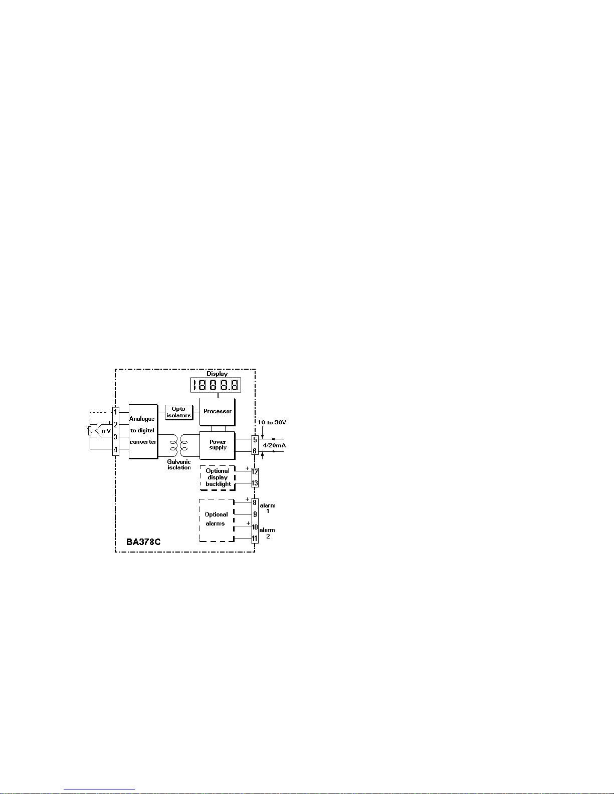
Fig 1 Simplified block diagram
2. OPERATION
Fig 1 shows a simplified block diagram of the
transmitter. The input signal, which may be from a
thermocouple, resistance thermometer or a dc
voltage, is digitised and transferred to the
instrument processor via an optical isolator. The
processor scales the signal and for temperature
measurement applies linearisation using look-up
tables stored in permanent memory. The resulting
temperature is shown on the internal display and
controls the 4/20mA output current.
The transmitter and the optional alarms are
powered from the 4/20mA current loop, but the
optional display backlight requires a separate
supply.
Each time power is applied to the instrument,
initialisation is performed. After a short delay the
following display sequence occurs:
-1.8.8.8.8 Display test in which all
segments of the display
are activated for 2.5
seconds.
. . . . For 1 second
0 For less than 0.5
seconds.
Input signal Using calibration
displayed information stored in
instrument memory.
2.1 Controls
All functions of the transmitter can be programmed
on-site via four front panel push-buttons. In the
display mode i.e. when the transmitter is displaying
the input signal, these push-buttons have the
functions listed below. The 4/20mA transmitter
output current is not affected when these
push-buttons are operated.
Button Function
Down While this button is pushed the
transmitter will show the display
corresponding to a 4mA output.
Up While this button is pushed the
transmitter will show the display
corresponding to a 20mA output.
For transmitters fitted with alarms
E+Up While these buttons are pushed the
transmitter will display setpoint 1.
E+Down While these buttons are pushed the
transmitter will display setpoint 2.
It is also possible to adjust the two alarm setpoints
from the display mode - see section 11.4
5
Page 6
3. INTRINSIC SAFETY CERTIFICATION
3.1 ATEX certificate
The BA378C has been issued with an EC-Type
Examination Certificate number BAS02ATEX1185X
by EECS showing compliance with the European
ATEX Directive 94/9/EC for Group II, Category 1
gas atmospheres, EEx ia IIC T5. The instrument
bears the Community Mark and, subject to local
codes of practice, may be installed in any of the
European Economic Area (EEA) countries. i.e.
Austria, Belgium, Denmark, Finland, France,
Germany, Greece, Ireland, Italy, Luxembourg, The
Netherlands, Norway, Portugal, Spain, Sweden,
Switzerland and the United Kingdom. ATEX
certificates are also accepted in Norway, Iceland,
Liechtenstein, Switzerland and the Czech Republic.
This manual describes installations which conform
with BS EN60079: Part 14: 1997 Electrical
Installation in Hazardous Areas. When designing
systems for installation outside the UK, the local
Code of Practice should be consulted.
3.2 Other intrinsic safety certifications
Please contact BEKA for a list of non-European
intrinsic safety approvals.
3.3 Zones, Gas Groups and T rating
The BA378C and accessories have been certified
EEx ia IIC T5. When connected to an approved
system the transmitter may be installed in:
Zone 0 explosive gas air mixture
continuously present.
Zone 1 explosive gas air mixture likely
to occur in normal operation.
Zone 2 explosive gas air mixture not
likely to occur, and if it does,
it will only exist for a short time.
Be used with gases in groups:
Group A propane
Group B ethylene
Group C hydrogen
Having a temperature classification of:
T1 450
o
C
T2 300
o
C
T3 200
o
C
T4 135
o
C
T5 100
o
C
This allows the BA378C to be installed in all Zones
and to be used with most common industrial gases
at ambient temperature between -40 and +60
o
C.
Note: minimum operating temperature is -20
o
C.
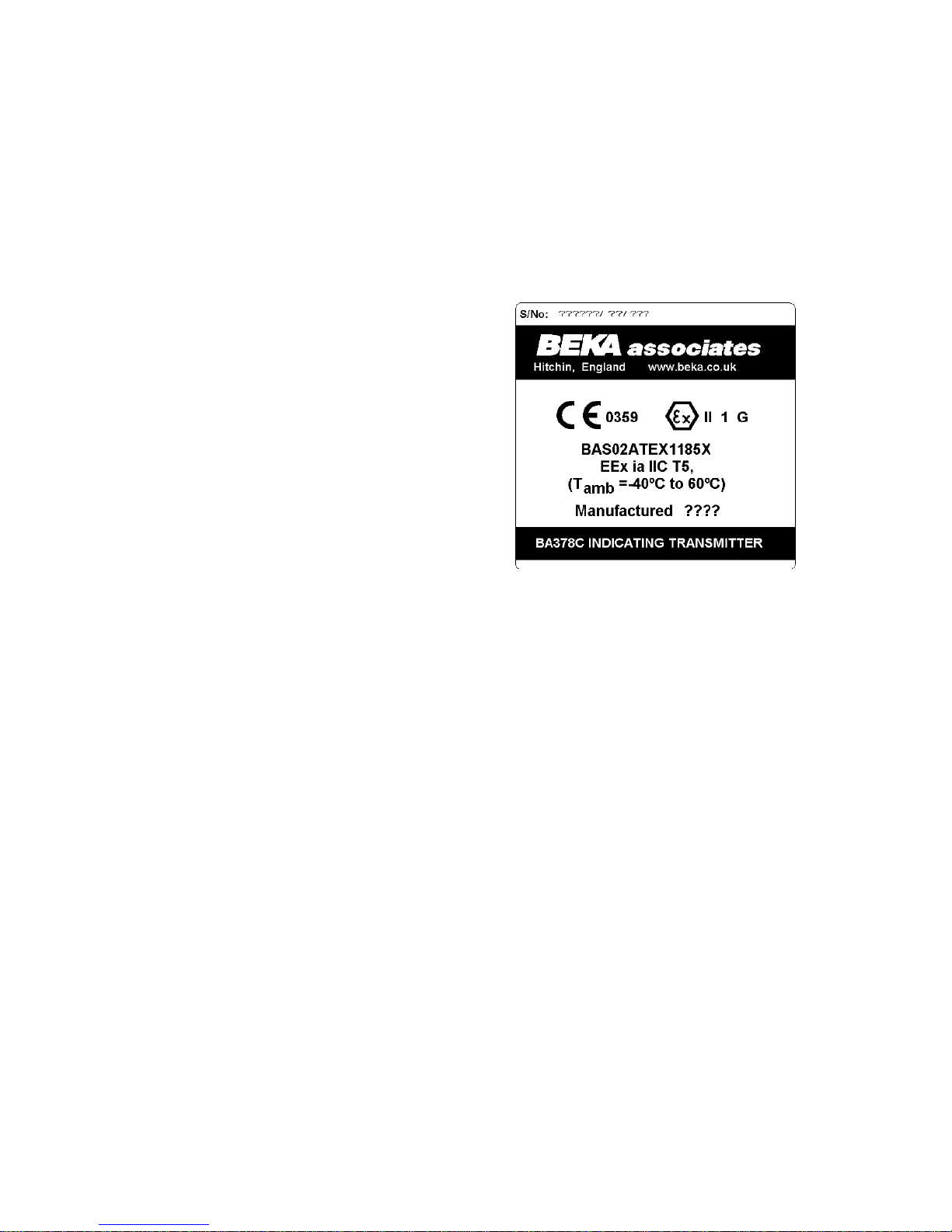
3.4 Certification information label
The certification information label, which is fitted on
the side of the instrument, shows the ATEX
certification information plus the instrument serial
number and date of manufacture.
3.5 Input terminals 1, 2, 3 & 4
When the BA378C is installed in a hazardous area
the input terminals may be connected to any
floating or earthed sensor complying with the
requirements for simple apparatus as defined in
Clause 5.4 of EN50020:1994. i.e. the sensor
generates less than 1.5V, 100mA, or 25mW.
Thermocouples and resistance thermometers are
simple apparatus and any floating or earthed
device may be connected to the BA378C, providing
that both are installed within the hazardous area.
The permitted maximum parameters for the cables
connecting the transmitter to the sensor are 4µF
and 9.2mH in the most onerous gas group IIC
(hydrogen). These are large and are very unlikely
to be exceeded on any thermocouple or resistance
thermometer installation.
If the transmitter input is to be connected to a
device which does not comply with the
requirements for simple apparatus, a system
certificate should be obtained, or the safety of the
system assessed using the entity concept. The
certified safety description of the BA378C input
terminals is:
Uo = 8.61V
Io = 62mA dc
Po = 0.14W
6
Page 7
3.6 4/20mA output - terminals 5 & 6
The BA378C transmitter is powered via these
terminals, and the current drawn is the 4/20mA
output signal. The transmitter is normally powered
from the safe area so a Zener barrier or galvanic
isolator is required to protect the circuit. Any single
channel Zener barrier or galvanic isolator certified
EEx ia IIC by an EEC approved body with output
safety parameters equal to, or less than, those
shown below may be used.
Uo = 30V
Io = 280mA dc
Po = 0.85W
4. ELECTRICAL SYSTEM DESIGN FOR
INSTALLATION IN HAZARDOUS AREAS
4.1 Using Zener barriers
There are three basic requirements when designing
a loop incorporating the BA378C:
1. The intrinsic safety parameters of the Zener
barrier must be equal to or less than:
Uo = 30V
Io = 280mA
Po = 0.85W
2. The voltage between terminals 5 & 6 of the
BA378C must be between 10 and 30V.
3. The maximum supply voltage must not
exceed the maximum working voltage of the
Zener barrier.
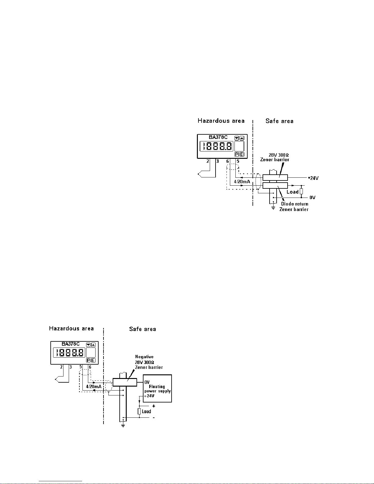
Fig 2 illustrates the simplest configuration in which a
BA378C is powered from an isolated (floating)
power supply. Only one barrier is required as the
other wire is earthed at the barrier busbar.
Fig 2 BA378C powered from floating supply
If a common power supply is used to operate more
than one loop the negative side of the supply is
normally connected to earth. To enable the
negative side of the 4/20mA load also to be
earthed it is necessary to have a Zener barrier in
each wire going into the hazardous area as shown
in Fig 3. Any certified diode return barrier may be
used in the return wire, for guidance System
Certificate Ex96D2505 lists some of these devices.
Fig 3 BA378C powered from a common supply
When designing any loop it is necessary to
establish that the sum of the voltage drops caused
by the BA378C transmitter, both Zener barriers, the
load and the cable resistance is less than the
minimum supply voltage.
For the transmitter loop shown in Fig 3:
Minimum operating voltage of BA378C 10.0V
Maximum voltage drop caused by 28V 6.8V
300ohm Zener barrier
(340ohms x 20mA)
Maximum voltage drop caused by 1.3V
diode return barrier
Maximum voltage drop caused by
250ohm load 5.0V
(250ohms x 20mA)
Maximum voltage drop caused by cable 0.2V
resistance (10ohms x 20mA)
_____
Total maximum voltage drop 23.3V
The power supply must therefore be above 23.3V,
but below the maximum working voltage of the 28V
300ohm Zener barrier which is typically 25.5V.
7
Page 8
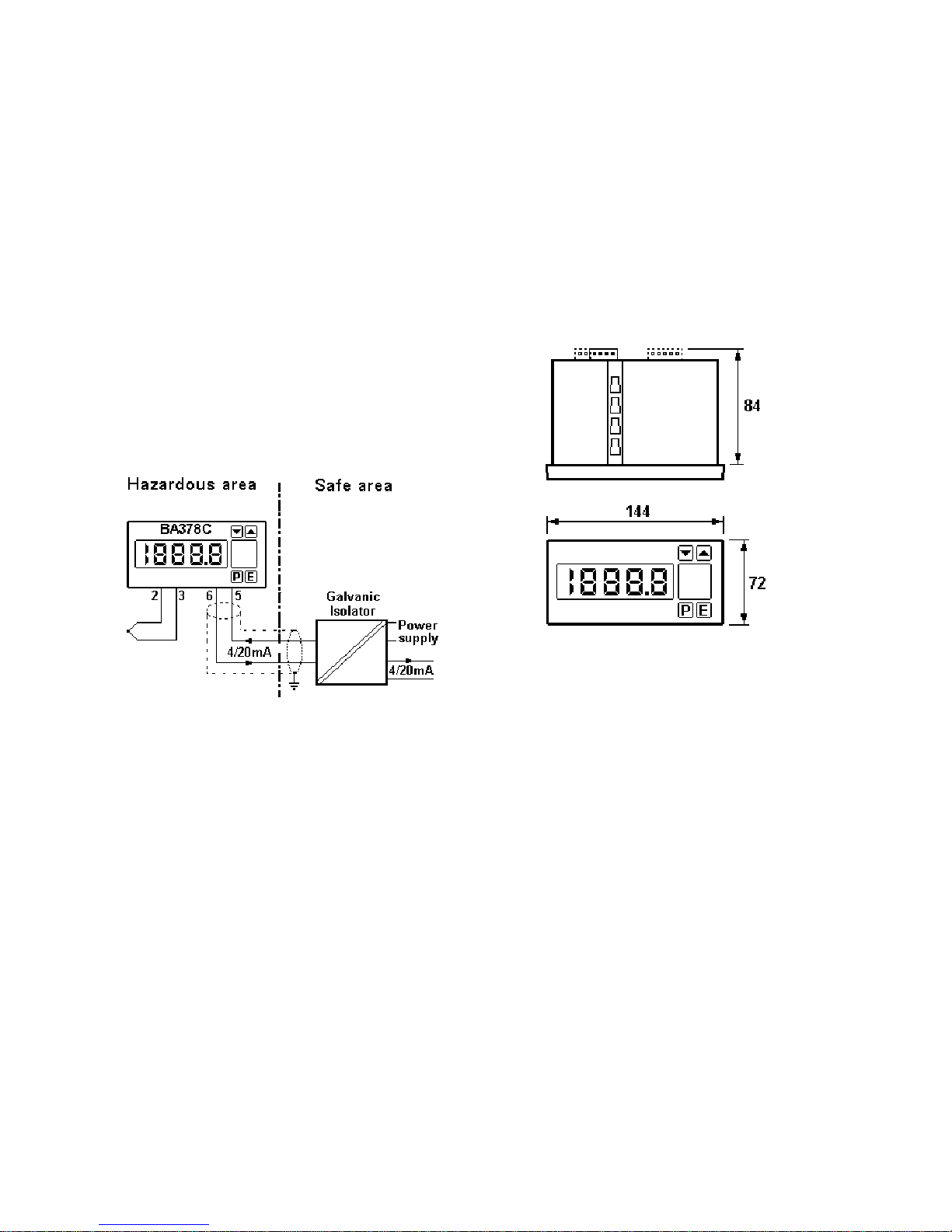
4.2 Using Galvanic Isolators
Galvanic isolators, although more expensive than
Zener barriers, do not require a high integrity earth
connection. For small systems where a high
integrity earth is not already available, the use of a
galvanic isolator often reduces overall installation
cost and will simplify the design of the loop.
Galvanic isolators also enable higher resistance
loads to be driven by the 4/20mA current.
Any EEx ia IIC certified isolator with output safety
parameters equal to or less than the following may
be used:
Uo = 30V
Io = 280mA
Po = 0.85W
For guidance System Certificate Ex96D2506.
lists some of the devices which may be used
Fig 4 shows a typical loop.
Fig 4 Typical application using galvanic isolators
5. INSTALLATION
The BA378C indicating temperature transmitter
should only be installed and operated by trained
competent personnel.
5.1 Location
The BA378C indicating transmitter is housed in a
robust aluminium enclosure with a polyester front
panel and Noryl bezel. The front panel provides
IP65 protection and a gasket seals the joint
between the instrument and the panel. The transmitter must be positioned such that the environmental conditions specified by the instrument
datasheet and the EC-Type Examination Certificate
are not exceeded, and it will not be attacked by
aggresive substances.
Please consult BEKA associates if the instrument is
to be installed in an area subject to high vibration.
Fig 5 shows the overall dimensions of the BA378C.
Recommended panel cut-outs are as detailed
below.
a) DIN 43 700
138.0 +1.0 / -0.0mm
68.0 +0.7 / -0.0mm
b) To achieve IP65 seal between instrument and
panel
136.0 +0.5 / -0.0mm
66.2 +0.5 / -0.0
mm
Fig 5 BA378C dimensions
5.2 Installation Procedure
Figs 6a and 6b illustrate the instrument installation
procedure.
a. Insert the instrument into the panel aperture
from the front of the panel as shown in Fig
6a.
b. Fix two panel mounting clips to opposite sides
of the instrument and tighten until the
instrument is secure.
Four clips will be required to achieve an IP65
seal between the instrument and the panel.
c. Connect the panel wiring to the rear terminal
block(s) as shown in Fig 6b.
WARNING!
To prevent damage to the static
dissipative coating on the front panel &
bezel of the instrument, only soap and
water should be used for cleaning
Solvents and abrasives must not be
used.
8
Page 9
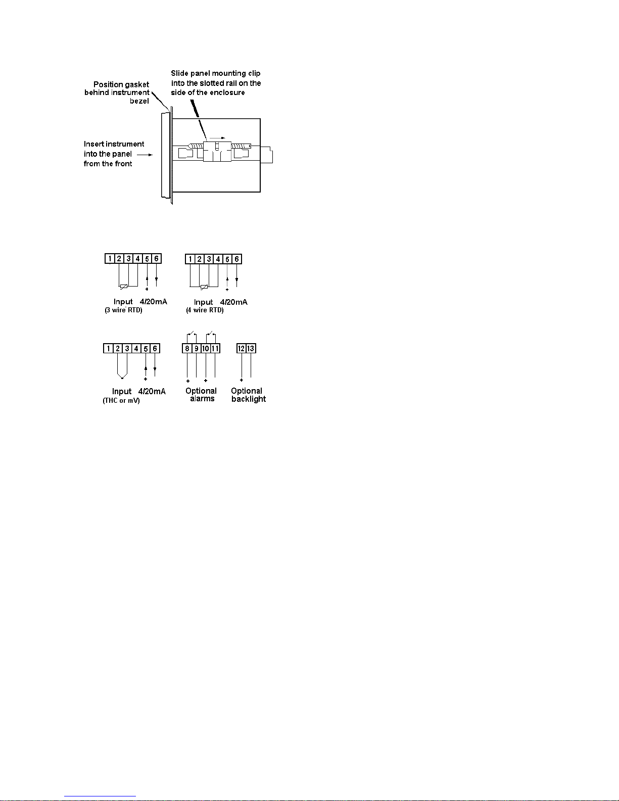
Fig 6a Installation into panel
Fig 6b Instrument wiring
5.3 EMC
The BA378C complies with the requirements of the
European EMC Directive. For specified immunity
all wiring should be in screened twisted pairs.
6. PROGRAMMING AND CALIBRATION
The BA378C is programmed and calibrated via four
front panel push-buttons. All the functions are
contained in two easy to use menus, the
Programme Menu and the Trim Menu, which are
shown diagramatically in Figs 7A, 7B and 9.
The Programme Menu contains all the transmitter
parameters and enables calibration to be
performed against the internal transmitter references.
The Trim Menu enables the transmitter display and
the 4/20mA output current to be calibrated against
an external standard, such as a voltage source or
temperature calibrator. This is the preferred
method of calibration. A complete loop may be
calibrated using this menu to minimise errors resulting from primary element and load inaccuracies
.
Each function in the Programme Menu is summarised in section 6.1 and includes a cross reference
to more detailed information in following sections.
Although this simple menu driven system enables
most adjustments to be made without repeated
reference to this manual, we recommend that the
summary of the programme menu, calibration
procedure using the trim menu and the calibration
example in sections 6.1, 7.1 and 8 are read prior
to changing function or calibrating the transmitter.
Figs 7A, 7B and 9 show the structure of the
menus.
Details of the Trim Menu are contained in section 7
which also describes periodic calibration.
When the transmitter is fitted with alarms additional
functions are added to the programme menu.
These are described in section 11 of this manual.
Throughout this manual push-buttons are shown in
italics e.g. P or Up push-button, and legends
displayed by the transmitter are shown within
inverted commas e.g. 'CAL' and ' ALr2'.
Access to the Programme Menu is obtained by
operating the P and E push-buttons simultaneously.
If the transmitter is not protected by a security
code the first parameter 'InPut' will be displayed. If
the transmitter is protected by a security code,
'COdE' will be displayed first. Pressing P again will
enable the security code to be entered digit by digit
using the Up and Down buttons to change the flashing digit, and the P push-button to move to the next
digit. If the correct code is entered pressing E will
cause the first parameter 'InPut' to be displayed.
If an incorrect code is entered, or no button is
pressed for ten seconds, the transmitter will
automatically return to the operating mode.
When the transmitter is in the programme menu the
4/20mA output current will remain locked at the
value prior to starting programming, and it will
therefore not respond to any input change.
However, calibration of the 4/20mA output via the
'CAL' function, or re-calibration of the 4/20mA
references via the 'Cond' function will change the
output current.
Once within the Programme Menu the required
parameter can be reached by scrolling through the
functions using the Up and Down push-buttons as
shown in Figs 7A and 7B. When returning to the
display mode following changes to any parameters,
the transmitter will display four decimal points for a
few seconds while the new information is stored in
permanent memory.
9
Page 10
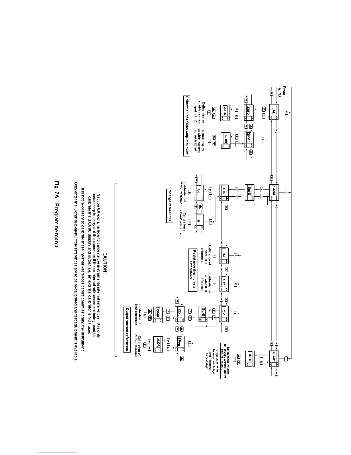
10
Page 11
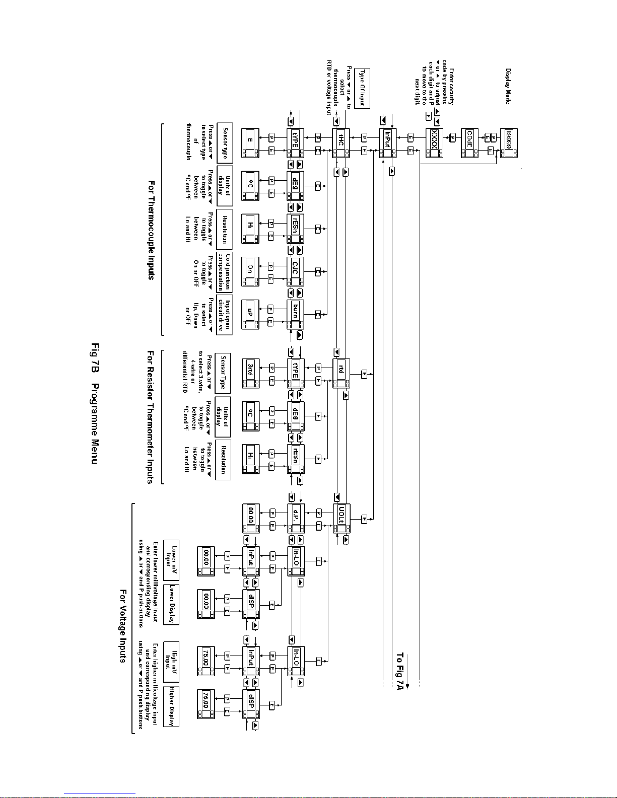
11
Page 12

All new BA378C indicators are supplied calibrated
as requested at the time of ordering. If calibration
is not requested, the transmitter will be set for 3
wire RTD input with 4 to 20mA output corresponding to a display of 0.0°C to 100.0°C .
6.1 Summary of Programme Menu functions
The parameters which may be programmed vary
depending upon which input is selected. For:
Thermocouple and resistance
thermometer inputs
The BA378C transmitter will always display
sensor temperature. Programming allows the
display to be in degrees Centigrade or Fahrenheit, and for the display resolution to be
selected.
Zero and span of the 4/20mA output current
may be programmed to represent any display
range.
Voltage input
The display may be programmed to show the
input voltage in any engineering units.
Zero and span of the 4/20mA output current
may be independently programmed to represent any displayed value.
Each of the functions in the Programme Menu is
described in the following summary with a cross
reference to more detailed information. Figs 7A
and 7B illustrate the location of each function within
the menu.
Display Summary of Programme Menu
functions
'InPut' Transmitter input
Conditions the transmitter to accept
thermocouple 'tHC', resistance
thermometer 'rtd' or a voltage 'UOLt'
input.
See section 6.2.1
Display Summary of Programme Menu
functions
For Thermocouple Inputs
'tYPE' Sensor type
Selects the type of thermocouple input.
See section 6.3.1
'dEg' Units of display
Sets display to
o
C or oF.
See section 6.3.2
'rESn' Display resolution
Selects low or high display resolution.
See section 6.3.3
'CJC' Cold junction compensation
Turns thermocouple cold junction
compensation ON or OFF.
See section 6.3.4
'burn' Input open circuit drive
Selects up scale drive, down scale drive
or no drive when input is open circuit.
See section 6.3.5
For Resistance Thermometer Inputs
'tYPE' Sensor type
Selects 3-wire, 4-wire or differential
Pt100 resistance thermometer input.
See section 6.4.1
'dEg' Units of display
Sets display to
o
C or oF.
See section 6.4.2
'rESn' Display resolution
Selects low or high display resolution.
See section 6.4.3
For Voltage Inputs
'd.P.' Decimal point
Positions the dummy decimal point
between any of the display digits or
turns it off.
See section 6.5.1
12
Page 13

Display Summary of Programme Menu
functions
'In-LO' Low input sub-menu
Enables the lower voltage input 'InPut'
and the corresponding display 'diSP' to
be defined.
See section 6.5.2
'In-HI' High input sub-menu
Enables the higher voltage input 'InPut'
and the corresponding display 'diSP' to
be defined.
See section 6.5.3
Other functions
'CAL' Calibration of 4/20mA output
This sub-menu defines the relationship
between the transmitter 4/20mA output
and the transmitter display. 'ZEro'
defines the display at which the output
is 4mA, and 'SPAn' the display at which
the output is 20mA.
See section 6.6
'Cond' Conditioning of internal references
WARNING!
Adjusting the internal
references will alter the
instrument performance. Do
not attempt to recalibrate these
references unless you have
adequate test equipment and
have read section 6.8
This sub-menu enables the internal
references to be calibrated against
external voltage, resistance and current
standards.
If the Trim Menu is used to calibrate the
transmitter, the internal references do
not require routine re-calibration.
See section 6.8
'COdE' Security code
Defines a four digit numeric code which
must be entered to gain access to the
programme and the trim menus.
Default code 0000 disables the security
function and allows unrestricted access
to all functions in the programme and
trim menus.
See section 6.7
6.2 Description of Programme Menu functions
The following sections contains a detailed
description of each function in the Programme
Menu. They should be read in conjunction with the
summaries in section 6.1 and the programme
structure shown in Figs 7A and 7B.
6.2.1 Transmitter input 'InPut'
This function conditions the transmitter to accept a
thermocouple 'tHC', resistance thermometer 'rtd' or
a voltage 'UOLt' input. To define the transmitter
input select 'InPut' from the Programme Menu and
press P which will reveal the current setting. This
setting may be changed by scrolling through the
menu using the Up or Down buttons. When the
required input is displayed, pressing P will reveal a
sub-menu enabling the type of sensor to be
selected and associated parameters programmed.
6.3 For thermocouple inputs
6.3.1 Type of thermocouple 'tYPE'
After selecting a thermocouple input, pressing P will
reveal the 'tYPE' sub-menu which contains seven
different thermocouples:
Type Display Standard
E E BS4937 Part 6 : 1974
J J BS4437 Part 3 : 1973
K h BS4437 Part 4 : 1973
N n BS4437 Part 8 : 1986
R r BS4937 Part 2 : 1973
T t BS4937 Part 5 : 1973
Pallaplat PALL Pfaulder BA302e
Pressing P again will display the current type of
thermocouple which may be changed by scrolling
through the menu using the Up or Down buttons.
When the required type is displayed, press E to
return to the sub-menu.
6.3.2 Display units 'dEg'
The transmitter display may be in degrees
centigrade or Fahrenheit. To check or change the
display units select 'dEg' from the sub-menu and
press P to reveal the current setting. The setting
may be changed by pressing the Up or Down
button. When the required units are displayed,
press E to return to the sub-menu.
6.3.3 Display resolution 'rESn'
The output of each type of thermocouple can be
displayed with high or low resolution as shown
below. Low resolution can improve the readability
of a noisy or rapidly changing display, but does not
degrade the performance of the 4/20mA analogue
output.
13
Page 14

High resolution is only available when the
transmitter is displaying temperature in
o
C. When oF
is selected the resolution is always one degree
To check or change the display resolution select
'rESn' from the sub-menu and press P to reveal the
current setting. The setting may be changed by
pressing the Up or Down button. When the required
resolution has been selected, press E to return to
the sub-menu.
Display Resolution
Type Low (Lo) High (Hi)
E1
o
C 0.1oC
J1
o
C 0.1oC
K1
o
C 0.2oC *
N1
o
C 0.2oC *
R1
o
C 0.4oC *
T1
o
C 0.1oC
Pallaplat 1
o
C 0.2oC *
* Worst case resolution figures are quoted, at
most temperatures resolution will be greater.
6.3.4 Cold junction compensation 'CJC'
The temperature of the transmitter input terminals,
which is the thermocouple cold junction, is
measured and added to the output from the
thermocouple so that the transmitter displays and
transmits the temperature relative to zero degrees
centigrade or Fahrenheit. If cold junction
compensation is not required, e.g. for differential
measurement with two thermocouples, this function
enables the cold junction compensation to be turned
off.
To turn the cold junction compensation on or off
select 'CJC' from the sub-menu and press P to
reveal the current status. The setting may be
changed by pressing the Up or Down button. When
set as required press E to return to the sub-menu.
6.3.5 Input open circuit drive 'burn'
If the thermocouple fails and becomes open circuit,
the transmitter can be conditioned to drive the
display and the 4/20mA output current up or down
into a safe condition. Alternatively the drive may be
turned off which will result in the display and the
4/20mA output current drifting towards zero when
the thermocouple breaks.
To check or change the input open circuit drive
select 'burn' from the sub-menu and press P to
reveal the current setting. The setting may be
changed by pressing the Up or Down button. When
the required setting has been selected, press E to
return to the sub-menu.
6.4 For resistance thermometer inputs
6.4.1 Types of resistance thermometer 'tYPE'
The transmitter may be conditioned to accept
3-wire, 4-wire or differential Pt100 resistance
thermometers.
After selecting resistance thermometer input from
the 'InPut' sub-menu, press P to reveal the 'tYPE'
sub-menu. Press P again to display the current
type of resistance thermometer which may be
changed by scrolling through the menu using the Up
or Down buttons. When the required type is
displayed, press E to return to the sub-menu.
6.4.2 Display units 'dEg'
The transmitter display may be in degrees
centigrade or Fahrenheit. To check or change the
display units select 'dEg' from the sub-menu and
press P to reveal the current setting. The setting
may be changed by pressing the Up or Down
button. When the required unit is displayed, press E
to return to the sub-menu.
6.4.3 Display resolution 'rESn'
The output of the resistance thermometer can be
displayed with high or low resolution as shown
below. Low resolution can improve the readability
of a noisy or rapidly changing display, but does not
degrade the performance of the 4/20mA analogue
output. High resolution is only available when the
transmitter is displaying temperature in
o
C. When oF
is selected the resolution is always one degree.
To check or change the display resolution select
'rESn' from the sub-menu and press P to reveal the
current setting. The setting may be changed by
pressing the Up or Down button. When the required
resolution has been selected, press E to return to
the sub-menu.
Display Resolution
Low High
1
o
C 0.1oC
6.5 For Voltage Inputs
When the transmitter is conditioned for a voltage
input both the input voltage range and the
corresponding display must be programmed.
6.5.1 Position of display decimal point 'd.P.'
A dummy decimal point can be positioned between
any of the display digits or it may be absent.
14
Page 15

After selecting voltage input from the 'InPut' menu,
press P to reveal the 'd.P.' sub-menu. Press P
again to display the current decimal point position.
The decimal point can be moved or turned off by
pressing the Up or Down push-button, followed by
E to return to the sub-menu.
6.5.2 Low input & display calibration 'In-LO'
This function defines the lower voltage input and the
corresponding transmitter display. See example
below:
Input Transmitter
mV Display
-10.00 -3.000 Low input / display
12.55 3.765 High input / display
The calibration is performed using the internal
references and may be made with any transmitter
input voltage.
Select 'In-LO' from the menu and press P which will
access a sub-menu containing two functions 'InPut'
and ''dISP'.
Select the input voltage 'InPut' and press P which
will cause the specified lower input millivoltage to
be displayed in the form XX.XX The flashing digit of
the input voltage can be changed by pressing the
Up or Down buttons. When the first digit is correct,
pressing P will transfer control to the next digit.
When the least significant digit has been adjusted,
press E to return to the 'InPut' prompt, from which
the display prompt 'dISP' can be selected by
pressing the Up or Down button.
Pressing P will reveal the transmitter display
corresponding to the specified low input voltage.
The position of the dummy decimal point will be as
defined by function 'd.P.' - see section 6.5.1
The flashing digit of the display can be changed by
pressing the Up or Down buttons. When the first
digit is correct, pressing P will transfer control to
the next digit. When the least significant digit has
been adjusted, press E to return to the ''dISP'
prompt.
6.5.3 High input & display calibration 'In-HI'
This function defines the higher voltage input and
the corresponding transmitter display. See
example below:
Input Transmitter
mV Display
-10.00 -3.000 Low input / display
12.55 3.765 High input / display
The calibration is performed using the internal
references and may be made with any transmitter
input voltage.
Select 'In-HI' from the menu and press P which will
access a sub-menu containing two functions 'InPut'
and ''dISP'.
Select the input voltage 'InPut' and press P which
will cause the specified higher input millivoltage to
be displayed in the form XX.XX The flashing digit of
the input voltage can be changed by pressing the
Up or Down buttons. When the first digit is correct,
pressing P will transfer control to the next digit.
When the least significant digit has been adjusted,
press E to return to the 'InPut' prompt, from which
the display prompt 'dISP' can be selected by
pressing the Up or
Down button.
Pressing P will reveal the transmitter display
corresponding to the specified higher input voltage.
The position of the dummy decimal point will be as
defined by function 'd.P.' - see section 6.5.1
The flashing digit of the display can be changed by
pressing the Up or Down buttons. When the first
digit is correct, pressing P will transfer control to
the next digit. When the least significant digit has
been adjusted, press E to return to the ''dISP'
prompt.
6.6 4/20mA output current calibration 'CAL'
This sub-menu defines the relationship between the
transmitter display and the 4/20mA output current.
The transmitter output current is derived from the
transmitter display and will change if the display
calibration is changed. 'ZEro' defines the display
at which the output is 4mA, and 'SPAn' the display
at which the output is 20mA.
To calibrate the output current select 'CAL' from the
programme menu and press P which will access a
sub-menu containing two functions. Select 'ZEro'
and press P which will show the transmitter display
at which the output current is 4mA. The flashing
digit of the display can be changed by pressing the
Up or Down buttons. When the first digit is correct,
pressing P will transfer control to the next digit.
When the least significant digit has been adjusted,
press E to return to the 'ZEro' prompt, from which
the span prompt 'SPAn' can be selected by
pressing the Up or Down button.
15
Page 16
Press P to show the transmitter display at which
the output current is 20mA. The flashing digit of the
display can be changed by pressing the Up or
Down buttons. When the first digit is correct,
pressing P will transfer control to the next digit.
When the least significant digit has been adjusted,
press E to return to the 'SPAn' prompt.
Note: If a complete loop including a primary
element, BA378C temperature transmitter and a
load are being calibrated, the Trim Menu is the
preferred method. It allows the transmitter display
and output current to be adjusted to compensate
for inaccuracies in the other components in the
loop. Details of the trim menu are contained in
section 7 which also describes periodic calibration.
6.7 Security Code 'COdE'
Access to the Programme and Trim Menus may be
protected by a four digit numerical security code
which must be entered before access is granted.
New instruments are programmed with the default
security code 0000 which allows unrestricted
access to both menus.
To enter a new security code select 'COdE' from
the Programme Menu and press P which will cause
the transmitter to display the current security code.
Each digit of the code can be changed using the Up
and Down push-buttons, and the P button to move
to the next digit. When the required code has been
entered press E to return to the main menu. The
revised security code will be activated when the
transmitter is returned to the display mode.
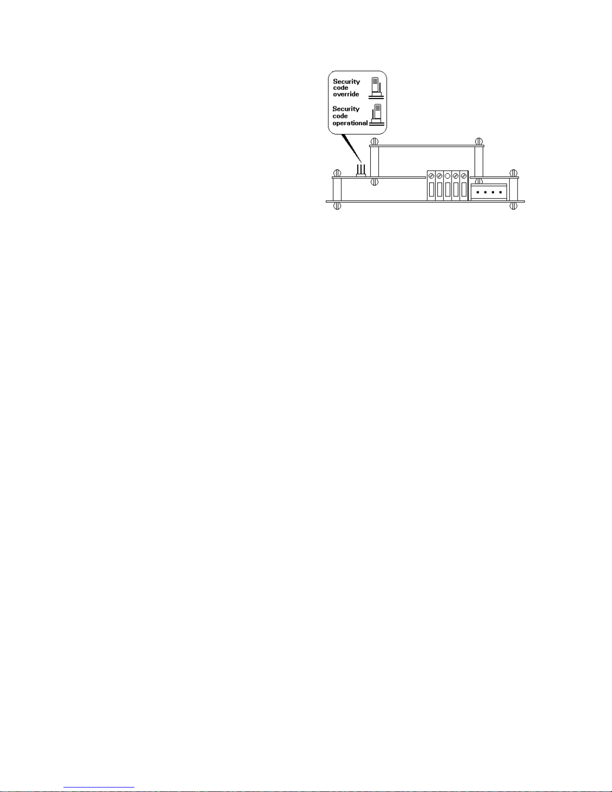
If the security code is lost, access to the
programme and Trim Menus can be obtained by
putting the internal security link in the override
position - see Fig 8. The security code can then be
viewed by selecting 'COdE' from the menu and
pressing P.
To access the security code link un-plug the
removable terminal(s) from the rear of the
instrument by gently pulling, and remove the
instrument rear panel which is secured by six
screws. The link can then be moved to the override
positioned as shown in Fig 8.
Fig 8 Location of security code override link
6.8 Calibrating the internal references
WARNING!
Changing the internal references will
alter the instrument performance. Do
not attempt to recalibrate these
references unless you have adequate
test equipment and have read the
following instructions. For routine
calibration of the instrument use the
Trim Menu described in Section 7.
If the Trim Menu is not used for routine calibration
of the BA378C transmitter, for maximum accuracy
the internal references may require periodic
checking against external standards. Annual checks
will produce acceptable performance, although less
frequent checks are usually adequate.
If the BA378C transmitter is calibrated against an
external voltage, resistance or temperature
calibrator using the Trim Menu, the internal
references should never need re-calibrating.
Details of the Trim Menu are contained in
section 7.
There are four internal references:
Voltage input
3-wire RTD
4-wire RTD
Current output
The input voltage reference must be adjusted first
irrespective of the transmitter application, but it is
only necessary to adjust the other three references
if the function to which they relate is being used.
For example, a BA378C with a thermocouple input
from which the 4/20mA output current is being used
would require the voltage input and the current
output reference adjusting.
16
Page 17

6.8.1 Conditioning internal references: 'Cond'
WARNING!
Changing the internal references will
alter the instrument performance. Do
not attempt to recalibrate these
references unless you have adequate
test equipment and have read the
following instructions. For routine
calibration of the instrument use the
Trim Menu described in Section 7.
These functions are contained in a protected
sub-menu to minimise the possibility of accidental
adjustment. Select 'Cond' from the menu and press
P. The transmitter will display '0000'. Using the UP
and Down buttons and the P button to move to the
next digit enter the password 'SurE'. (Note that 'S'
is entered as '5') Pressing E will then give access
to a sub-menu containing the four references.
There is a ten second time-out on entering the
password.
6.8.2 Voltage input reference 'U.IP'
With the BA378C input terminals connected to an
accurate voltage calibrator, select 'U.IP' from the
'Cond' sub-menu and press P. The transmitter will
respond by displaying 'Lo' which is a request for an
accurate -75.000mV input. Adjust the external
voltage calibrator to supply -75.00mV and press P
to store this figure in permanent memory. The
transmitter will display scrolling decimal points while
the reference is being updated and will then return
to the 'Lo' prompt.
Select 'Hi' from the sub-menu which is a request for
an accurate +75.000mV input. When the input is
correct press P to store this figure in permanent
memory. The transmitter will display scrolling
decimal points while the reference is being updated
and will then return to the 'Hi' prompt. This
completes adjustment of the voltage input
reference.
6.8.3 3-wire RTD reference '3rtd'
This adjustment, which is only necessary if the
transmitter is used with a three wire resistance
thermometer, should be performed after the
voltage reference has been calibrated. To adjust
the 3-wire RTD reference the resistance
thermometer should be replaced by a 100 ohm
standard resistor or calibrator, with the
compensation loop remaining connected between
terminals 3 and 4. It is preferable to make this
substitution as close to the RTD as possible, but
transmitters may be calibrated in a workshop.
Select '3rtd' from the 'Cond' sub-menu and press P.
The transmitter will display scrolling decimal points
while the reference is being updated followed by
'Ent' prior to returning to the '3rtd' prompt. This
completes adjustment of this reference.
6.8.4 4-wire RTD reference '4rtd'
This adjustment, which is only necessary if the
transmitter is used with a four wire resistance
thermometer, should be performed after the
voltage reference has been calibrated. To adjust
the 4-wire RTD reference the resistance
thermometer should be replaced by a 100 ohm
standard resistor or calibrator, with both
compensation loops from terminals 1 and 4
connected at the standard resistor or calibrator. It
is preferable to make this substitution as close to
the RTD as possible, but if necessary the
transmitter may be calibrated in a workshop.
Select '4rtd' from the 'Cond' sub-menu and press P.
The transmitter will display scrolling decimal points
while the reference is being updated followed by
'Ent' prior to returning to the '4rtd' prompt. This
completes adjustment of this reference.
6.8.5 Output current reference 'OP'
Warning: ensure plant safety
before performing this adjustment
This adjustment is only necessary if the transmitter
4/20mA output current is used. A method of
accurately measuring the transmitter output current,
such as a DVM, is required to calibrate this
reference.
Select 'OP' from the 'Cond' sub-menu and press P,
the transmitter will display 'Sure'. If it is safe to
change the transmitter output current between 4
and 20mA continue by pressing P. The transmitter
will display 'ZEro', pressing P again will change the
display to '.004A' and the transmitter output current
to approximately 4mA.
The transmitter output current shown on the
external current measuring instrument should be
adjusted to 4.000 ±0.001mA using the transmitter
Up and Down buttons. When correct press the E
push-button to return to the 'ZEro' prompt.
17
Page 18
To adjust the 20mA output current reference select
the 'SPAn' prompt by operating the Up or Down
button. Pressing P will change the display to
'.020A' and the transmitter output current to
approximately 20mA. The transmitter output current
shown on the external current measuring instrument
should be adjusted to 20.000 ±0.001mA using the
transmitter Up and Down buttons. When correct
press the E push-button twice to return to the 'OP'
prompt. This completes calibration of the output
current reference.
7. TRIM MENU
The Trim Menu is the preferred method of routine
calibration. It enables the BA378C transmitter to be
adjusted using an external voltage, resistance or
temperature calibrator. For maximum accuracy the
complete loop including the thermocouple or
resistance thermometer may be calibrated by
heating or cooling the primary element.
Before using the Trim Menu all the functions in the
'InPut' and 'CAL' sections of the programme menu
must be defined, including the 4/20mA output
range. For voltage inputs, both the millivoltage
input and the corresponding display range must be
entered.
If a voltage calibrator is used to simulate a
thermocouple the transmitter cold junction
compensation must be turned off. Alternatively, the
temperature at the BA378C input terminals may be
measured and the voltage calibrator corrected for
ambient temperature, although this is likely to
produce less accurate results.
7.1 Calibration procedure using Trim Menu
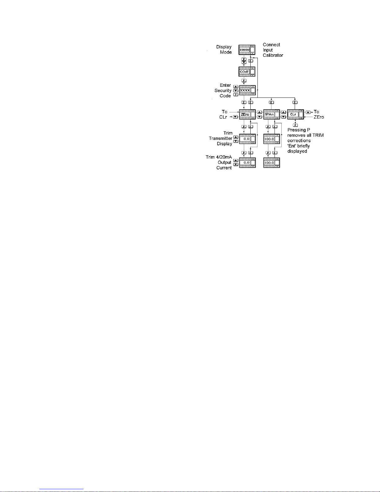
The structure of the Trim Menu is shown in Fig 9.
Access to the menu is obtained by operating the P
and Down push-buttons simultaneously. If the
transmitter is not protected by a security code the
first parameter 'ZEro' will be displayed. If the
transmitter is protected by a security code, 'COdE'
will be displayed first. Pressing P again will enable
the security code to be entered digit by digit, using
the Up and Down buttons to change the flashing
digit, and the P push-button to move to the next
digit. If the correct code is entered pressing E will
cause the first parameter 'ZEro' to be displayed.
If an incorrect code is entered, or if no button is
pressed for ten seconds, the transmitter will
automatically return to the display mode.
Fig 9 Trim Menu
The 'ZEro' sub-menu allows the transmitter display
and output current to be independently trimmed at
the bottom of the input range. To make the adjustment connect a calibrator to the transmitter input
terminals to simulate minimum input, or place the
primary element in a vessel at the minimum
temperature. With 'ZEro' displayed, pressing the P
push-button will cause the temperature display to
return. If the display does not correspond with the
input calibrator or the temperature of the primary
element, operate the Up or Down button until the
transmitter display is correct. Immediately the Up
or Down button is operated the annunciator in the
top left hand corner of the display will be activated
to warn that any changes in the input signal will be
ignored while this display correction is being made.
When the transmitter display is correct, press P
which will lock the transmitter display and, after
briefly displaying 'Ent', allow the 4/20mA output
current to be trimmed using the Up or Down pushbutton. The output current should be measured
with an accurate DVM or another instrument within
the loop. Operate the Up or Down buttons until the
required output current is shown on the DVM or
other instrument. When correct, press the E button
to store the trim correction in permanent memory
and return the BA378C transmitter to the 'ZEro'
prompt. This completes re-calibration of the
BA378C transmitter at minimum input.
18
Page 19

The transmitter should now be re-calibratied at
maximum input by selecting the 'SPAn' sub-menu
and adjusting the calibrator to simulate maximum
input, or raising the primary element to maximum
temperature. With 'SPAn' displayed, pressing the
P push-button will cause the temperature display to
return. If the display does not correspond with the
input calibrator or the temperature of the primary
element, operate the Up or Down buttons until the
transmitter display is correct. Immediately the Up
or Down button is operated the annunciator in the
top left hand corner of the display will be activated
to warn that any changes in the input signal will be
ignored while this display correction is being made.
When the transmitter display is correct, press P
which will lock the transmitter display and, after
briefly displaying 'Ent', allow the 4/20mA output
current to be trimmed using the Up or Down pushbutton. Again the output current should be
measured with an accurate DVM or another instrument within the loop. Operate the Up or Down
buttons until the required output current is shown on
the DVM or other instrument. When correct, press
the E button to store the trim correction in permanent memory and return the BA378C transmitter to
the 'SPAn' prompt. This completes re-calibration
of the BA378C transmitter at maximum input.
When calibrating the BA378C using the Trim Menu
both the zero and span must be adjusted.
The Trim Menu contains a clear function which
enables the small calibration correction made with
the 'ZEro' and 'SPAn' sub-menus to be removed.
To clear the corrections select 'CLr' from the Trim
Menu and press P. The display will show 'Ent' for a
short while and then return to the ''CLr' prompt.
7.2 Periodic re-calibration using Trim Menu
The Trim Menu is the preferred method of making
small calibration adjustments to compensate for
any long term drift which may occur. Initially an
annual check is recommended to achieve maximum
accuracy, although less frequent checks will usually
produce acceptable results.
If the BA378C internal references are used to make
frequent calibration changes, we recommend that
these references should be initially checked once
per year as described in sections 6.8.1 to 6.8.5 If
the BA378C is always calibrated with an external
reference, such as a voltage source using the trim
menu, it will not be necessary to check the internal
references.
8. CALIBRATION EXAMPLE
In this example a BA378C is required to display
with maximum resolution the temperature of a type
J thermocouple, and to transmit a 4/20mA signal
representing -10 to 240
o
C. If the thermocouple
breaks the 4/20mA output current is to rise to full
scale. The current security code is 1209.
The example is divided into two sections. Steps 1
to 10 explain how to condition the transmitter and to
calibrate the 4/20mA output using the internal
references. This will produce acceptable accuracy
for most applications, but will not compensate for
errors in the thermocouple or load connected to the
4/20mA output. Steps 11 to 13 describe how the
Trim Menu may be used to calibrate the complete
loop and to compensate for thermocouple errors.
Step 1 Initialisation
When power is applied to the loop the
BA378C will automatically perform the
initialisation routine described in section
2, and then display and transmit the
thermocouple temperature using the
existing calibration information.
Step 2 Enter the programme menu
Enter the programme menu by
simultaneously pressing the P and E
buttons. The transmitter will respond by
displaying 'COde'. Press P to clear this
prompt and set the display to the
security code 1209 using the Up, Down
and P push-buttons. Pressing E will
enter the code. After a few seconds
during which all the decimal points will
be activated, the first parameter 'InPut'
will be displayed.
Step 3 Define input
With 'InPut' displayed press P which
will reveal the current transmitter sensor
type. Using the Up or Down button
scroll through the menu until
thermocouple input 'tHC' is displayed.
Step 4 Define type of thermocouple
With 'tHC' displayed press P to enter
the thermocouple sub-menu. The first
parameter 'tYPE' will be displayed,
pressing P again will give access to the
seven different types of thermocouple.
Select 'J' using the Up or Down button
and then press E to return to the
sub-menu.
19
Page 20

Step 5 Define units of display
Using the Up or Down button select
'dEg', from the sub-menu and press P
to reveal the current units. Pressing the
Up or Down button will toggle between
o
C and oF. Select oC and press E to
return to the sub-menu.
Step 6 Resolution
Using the Up or Down button select
'rESn' from the sub-menu and press P.
Pressing the Up or Down button will
toggle between high and low resolution,
select 'Hi' and press E to return to the
sub-menu.
Step 7 Cold junction compensation
In this example only one thermocouple
is connected so cold junction
compensation is required. Using the Up
or Down button select 'CJC' from the
sub-menu and press P. The Up and
Down buttons will turn the cold junction
'On' and 'OFF'. Select 'On' and press E
to return to the sub-menu.
Step 8 Input open circuit drive
Using the Up or Down button select
'burn' from the sub-menu and press P to
reveal the current status. Select 'uP'
using the Up or Down button and press
E three times to return to the 'InPut'
prompt via the 'burn' and 'tHC' prompts.
Step 9 Calibrating the 4/20mA output
'CAL' defines the display at which the
output current is 4mA and 20mA.
Select 'CAL' from the menu using the
Up or Down push-button, and enter the
sub-menu by pushing P. The
transmitter will display a 'ZEro' prompt
requesting the display at which the
output is to be 4mA. Press P and
enter -10.0 using the Up, Down and P
buttons. Press E to return to the 'ZEro'
prompt. Select 'SPAn' from the
sub-menu and press P. Enter 240.0
which is the display at which the output
current is to be 20mA and press E
twice to return to the 'CAL' prompt.
Step 10 Return to the display mode
With the 'CAL' prompt displayed, press
E to store the conditioning and
calibration information and return to the
display mode. All the display decimal
points will be activated while the
information is being stored. This
completes the calibration of the
transmitter using the internal
references.
The following steps explain how, using the Trim
Menu, the BA378C transmitter may be calibrated
against an external reference, such as a voltage
source or temperature calibrator. Alternatively, the
complete loop including the primary element may
be calibrated by cooling and heating the
thermocouple to -10 and +240
o
C. This is the
preferred method for routine calibration.
Step 11 Entering the trim menu
Enter the trim menu by simultaneously
pressing the P and Down buttons - see
Fig 9. The transmitter will respond by
displaying 'COde' . Press P to clear
this prompt and set the display to the
security code 1209 using the Up, Down
and P push-buttons. Pressing E will
enter the code. After a few seconds
during which all the decimal points will
be activated, the first parameter 'ZEro'
will be displayed.
Step 12 Zero adjustment
This adjustment trims the display to
read exactly -10.0
o
C and the output
current to be exactly 4.000mA when the
type J thermocouple is at -10
o
C. This
can be achieved by cooling the
thermocouple to -10
o
C or by inputting
the voltage which the thermocouple
should theoretically produce. If a
voltage is used the transmitter cold
junction compensation (see section
6.3.4) should be turned off during the
calibration, or the input voltage should
be corrected for ambient temperature,
although this may be less accurate.
With the transmitter displaying the
'ZEro' prompt and the correct input
connected to the transmitter, push P
which will cause the transmitter to
display the thermocouple temperature.
Adjust the display with the Up and
Down buttons until it is -10.0
20
Page 21

Note: Immediately the Up or Down
button is operated the annunciator in the
top left hand corner of the display will
be activated to warn that any change in
the input signal will be ignored while this
display correction is being made.
Operating the P push-button will lock
the transmitter display at -10.0 and
allow the output current to be trimmed
using the Up or Down button. When the
output current measured by a DVM is
4.000mA, the E push-button should be
operated to return the transmitter to the
'ZEro' prompt.
This completes calibration at -10.0
o
C.
Step 13 Span adjustment
With the transmitter displaying the
'ZEro' prompt select 'SPAn' by pressing
the Up or Down button. With the
thermocouple heated to 240
o
C, or an
equivalent voltage input, push P which
will cause the transmitter to display the
thermocouple temperature. Adjust the
display with the Up and Down buttons
until it is 240.0
Note: Immediately the Up or Down
button is operated the annunciator in the
top left hand corner of the display will
be activated to warn that any change in
the input signal will be ignored while this
display correction is being made.
Operating the P push-button will lock
the transmitter display at 240.0 and
allow the output current to be trimmed
using the Up or Down button. When the
output current measured by a DVM is
20.000mA, the E push-button should be
operated to return the transmitter to the
'SPAn' prompt.
This completes calibration at 240.0
o
C.
Pressing the E push-button again will
return the transmitter to the display
mode.
9. MAINTENANCE
The instrument should only be maintained by trained
competent personnel.
9.1 Fault finding during commissioning
If the BA378C transmitter fails to function during
commissioning the following procedure should be
followed:
Symptom Cause Solution
No display Incorrect Check wiring
or output wiring or no and power
current power supply supply polarity
Check that voltage
between terminals
5 & 6 is between 10
and 30V with terminal
5 positive.
BA378C Positive The transmitter input
displays 1 display exceeds the upper
over-range operating range of the
selected THC or RTD.
For voltage inputs,
display is incorrectly
calibrated.
Check calibration.
BA378C Negative The transmitter input
displays -1 display is less than the lower
over-range operating range of the
selected THC or RTD.
For voltage inputs,
display is incorrectly
calibrated.
Check calibration.
Output fixed 4/20mA output The transmitter output
below 4mA current over, current is incorrectly
or above or under-range calibrated.
20mA. Check calibration.
9.2 Fault finding after commissioning
ENSURE PLANT SAFETY BEFORE
STARTING MAINTENANCE
Live maintenance is permitted on
intrinsically safe equipment installed in a
hazardous area, but only certified test
equipment should be used unless a gas
clearance certificate is available.
If a BA378C fails after it has been functioning
correctly the procedure shown in section 9.1 should
be followed.
21
Page 22

9.3 Servicing
The BA378C cannot be serviced on-site. Electronic
assemblies may be exchanged between
enclosures, but sub-boards must not be interchanged between electronic assemblies. All
BA378C transmitter functions are easily programmable on-site, a single spare transmitter may
therefore be used to replace any instrument which
fails.
Suspect instruments should be returned to BEKA
associates or our agent in your area
9.4 Routine maintenance
The mechanical condition of the instrument and the
electrical calibration (see section 7.2) should be
regularly checked. The interval between inspections depends upon the environmental conditions.
We recommend that initially this is performed
annually.
9.5 Guarantee
Transmitters which fail within the guarantee period
should be returned to BEKA associates or our local
agent. It is helpful if a brief description of the fault
symptoms and a list of error messages is provided.
9.6 Customer comments
BEKA associates is always pleased to receive
comments from customers about our products and
services. All communications are acknowledged
and whenever possible, suggestions are
implemented.
ACCESSORIES
10. IDENTIFICATION
10.1 Scale card
The BA378C has a window on the right hand side
of the display to hold a card showing the units of
measurement e.g.
o
C, oF, kg. The transmitter
can be supplied with a printed scale card showing
any units specified at time of ordering. If a printed
scale card is not requested a blank card will be
fitted.
Scale cards can easily be marked on site as
follows:
a. Un-plug the rear terminal block(s),
disconnect the input wires and remove the
rear panel which is secured by four corner
screws.
b. Withdraw the transmitter assembly from
the enclosure.
c. Gently pull and then slide the blank scale
card towards the display window until it is
free. Mark the card with the required
legend and replace it in the slot.
d. Insert the transmitter assembly into the
enclosure, fit the rear panel and terminal
blocks and reconnect the input wires.
10.2 Tag strip
The BA378C can be supplied with a thermally
printed tag strip on the rear panel with any legend
containing up to 35 alphanumeric characters. This
strip is not visible from the front of the instrument
after installation.
11. ALARMS
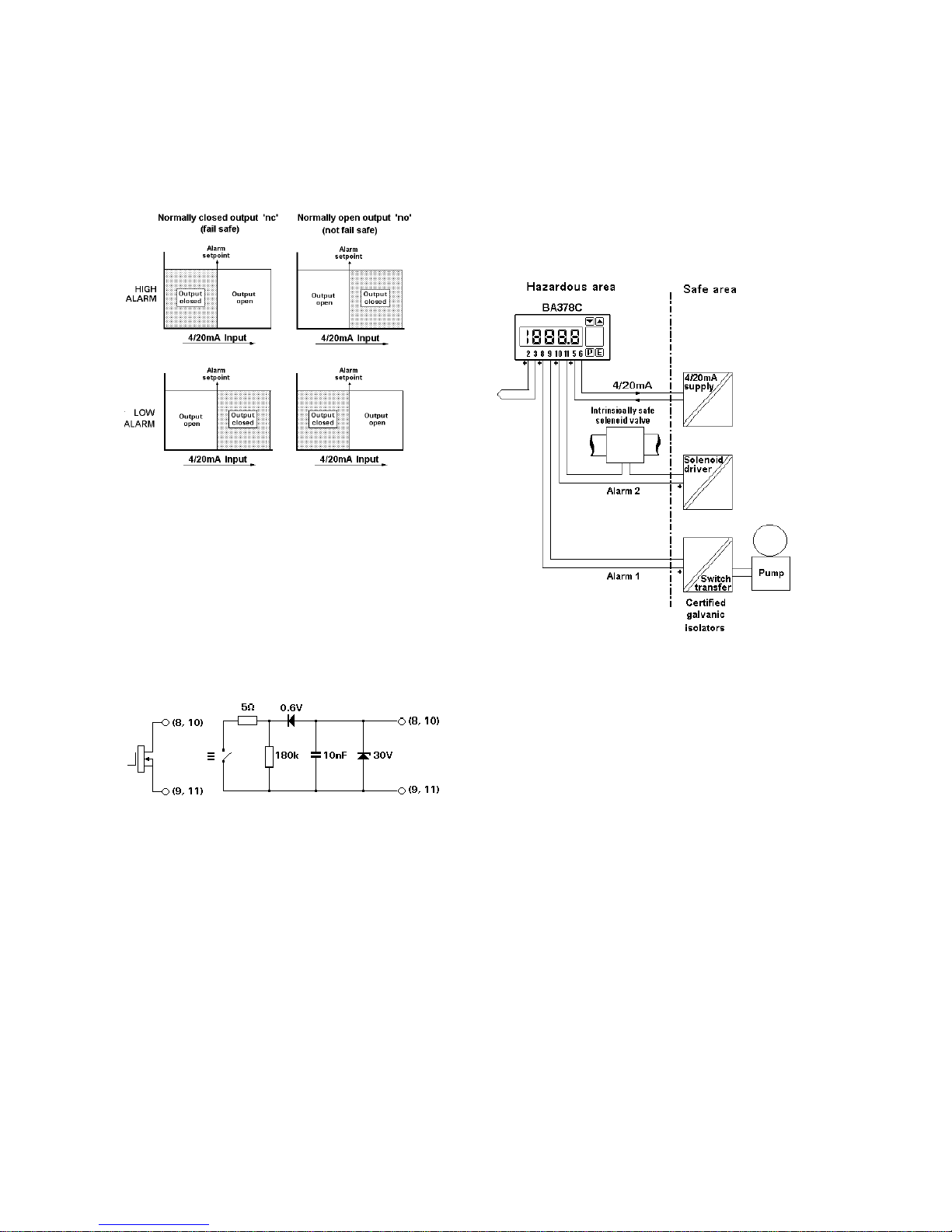
The optional alarms provide two solid state single
pole outputs which may be independently
programmed as high or low alarms with normally
open or normally closed outputs. Fig 10 illustrates
the conditions available and shows which are fail
safe, i.e. output is in the alarm condition (open)
when the transmitter is not powered. When an
alarm is activated the indicator display alternates
between the measured value and an alarm
identification.
22
Page 23
WARNING!
These alarm outputs should not be used
for critical safety applications such as a
shut-down system.
Fig 10 Alarm outputs
Programmable functions for each alarm include
adjustable hysteresis, alarm delay and alarm
accept.
11.1.1 Solid state output
Each alarm has a galvanically isolated single pole
solid state switch output as shown in Fig 11. The
output is polarised and current will only flow in one
direction.
Fig 11 Equivalent circuit of each alarm output
11.1.2 Intrinsic safety
Each alarm output is a separate galvanically
isolated solid state switch with certified output
parameters less than those specified for simple
apparatus in Clause 5.4 of EN50020. This allows
the alarm terminals 8 & 9 and 10 & 11 to be
connected to any intrinsically safe circuit protected
by a Zener barrier or galvanic isolator providing the
intrinsic safety output parameters of the circuit do
not exceed:
Uo = 30V dc
Io = 280mA
Po = 0.85W
The maximum equivalent capacitance and
inductance between each set of alarm terminals is:
Ceq = 40nF
Leq = 20µH
These figures must be subtracted from the
maximum permitted cable capacitance and
inductance specified by the system certificate of
the circuit connected to the alarm.
Fig 12 Typical application of alarms
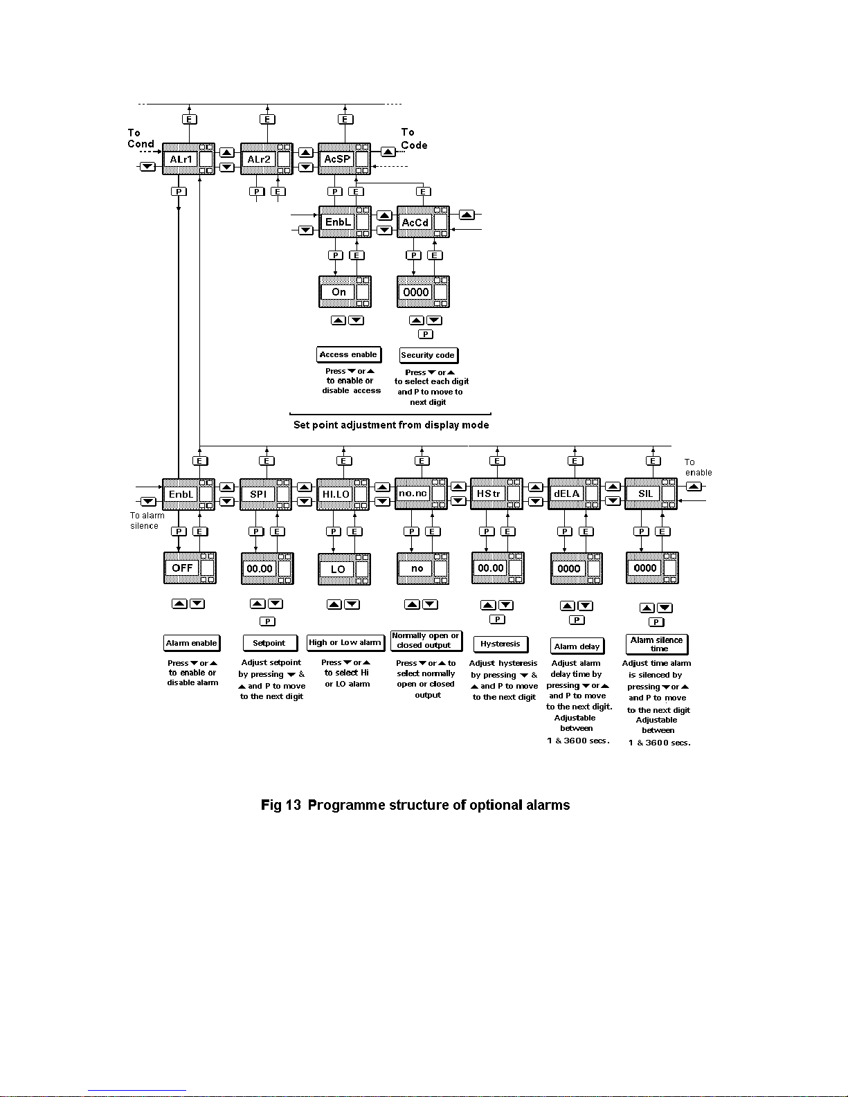
11.1.3 Programming & adjustment
When an alarm card is added to a BA378C
transmitter the main programme menu is extended
as shown in Fig 13. The additional functions
'ALr1', 'ALr2' and 'AcSP' appear between 'Cond'
and 'COde' in the programme menu. For simplicity
Fig 13 only shows the functions available on alarm
1, but alarm 2 has identical facilities.
The alarms relate to the digital display and the
setpoints are shown in the same units as the
display.
The following table summarises each of the alarm
programme functions and includes a cross
reference to more detailed information. Again only
the functions on alarm 1 are listed, but alarm 2 has
identical facilities.
23
Page 24

11.2 Summary of programmable
functions.
Display Summary of function
'EnbL' Alarm enable
Enables or disables the alarm function
without changing the alarm parameters.
See section 11.3.1
'SP1' Alarm setpoint 1
Adjusts the alarm setpoint. The alarm
is activated when the indicator display
equals the setpoint.
The setpoint can also be adjusted
directly from the operating mode.
See section 11.3.2
'HI.LO' Alarm function
Defines whether the alarm has a high or
low function
See section 11.3.3
'no.nc' Normally open or normally closed
output
Determines whether the single pole
alarm output is open or closed in the
alarm condition.
See section 11.3.4
'HStr' Hysteresis
Adjusts the alarm hysteresis.
See section 11.3.5
'dELA' Alarm delay time
Adjusts the delay between the display
equalling the setpoint and the alarm
output being activated.
See section 11.3.6
'SIL' Alarm silence time
Defines the time that the alarm output
remains in the non-alarm condition
following acceptance of an alarm.
See section 11.3.7
'AcSP' Access setpoint
Sub-menu which enables the function
allowing direct access to the alarm
setpoints from the transmitter display
mode, and defines a separate security
code.
See section 11.3.8
11.3 Description of programmable functions
The following sections contain detailed descriptions
of each programmable function. They should be
read in conjunction with the alarm programme
structure shown in Fig 13.
11.3.1 Alarm enable: EnbL
This function allows the alarm to be enabled or
disabled without altering any of the alarm
parameters. To check or change the function
select 'EnbL' from the alarm sub-menu and press P
which will reveal the current setting. The function
may be changed by pressing the Up or Down
button followed by the E button to return the 'EnbL'
prompt.
11.3.2 Setpoint adjustment: SP1 and SP2
The setpoint of each alarm relates to the
transmitter display, and each may be independently
positioned anywhere in the transmitter display
range. When positioned close to the display limits,
care should be taken to ensure that hysteresis
does not place the alarm beyond the display limits.
To adjust the setpoint select 'SP1' or 'SP2' from the
alarm sub-menu and press P which will reveal the
existing alarm setpoint. Each digit of the setpoint
may be adjusted using the Up and Down
push-buttons, and the P button to move to the next
digit. When the required setpoint has been entered
press E to return the setpoint prompt 'SP1' or
'SP2'.
11.3.3 Alarm function: HI.LO
Each alarm may be conditioned as a high or low
alarm. To check or change the alarm function
select 'HI.LO' from the alarm sub-menu and press
P to reveal the current setting. The function may
be changed by pressing the Up or Down buttons
followed by the E button to return the 'HI.LO'
prompt.
11.3.4 Alarm output status: no.nc
This function allows the alarm output to be open or
to be closed in the alarm condition. When deciding
which is required, care must be taken to ensure
that the alarm output is fail safe.
WARNING!
When the transmitter power supply
is removed both alarm outputs will
open irrespective of conditioning.
Therefore for fail safe operation both
alarm outputs should be
programmed to be open in the alarm
condition.
24
Page 25
25
Page 26

To check or change the alarm output status select
'no.nc' from the alarm sub-menu and press P to
reveal the current setting. The function may be
changed by pressing the Up or Down buttons
followed by the E button to return the 'no.nc'
prompt.
11.3.5 Hysteresis: HStr
To adjust the alarm hysteresis select 'HStr' from
the alarm sub-menu and press P which will reveal
the existing figure. Each digit can be adjusted using
the Up and Down push-buttons, and the P button to
move to the next digit. When the required hystersis
has been entered press E to return the 'HStr'
prompt.
e.g. A transmitter with a high alarm set at 240 and
hysteresis of 10 will perform as follows:
High alarm will be activated when display
equals or exceeds 240, but will not reset until
the display falls below 230.
11.3.6 Alarm delay: dELA
This function enables activation of the alarm output
to be delayed for a fixed time following the alarm
condition occurring. The delay can be programmed
in 1 second increments up to 3600 seconds. If a
delay is not required zero should be entered. To
adjust the delay select 'dELA' from the alarm
sub-menu and press P which will reveal the existing
delay. Each digit of the delay can be adjusted
using the Up and Down push-buttons, and the P
button to move to the next digit. When the required
delay has been entered press E to return the
'dELA' prompt.
11.3.7 Alarm silence time: SIL
This function is primarily intended for use in small
installations where the alarm output directly
operates an annunciator such as a sounder. When
the alarm silence time is set to any figure other than
zero, the P push-button becomes an alarm accept
button. After an alarm has occurred, operating the
P button will cause the alarm output to revert to
the non-alarm condition for the programmed alarm
silence time. The display will continue to indicate
an alarm after it has been accepted and silenced.
The alarm silence time may be adjusted between 0
and 3600 seconds in 1 second increments.
To adjust the alarm silence time select 'SIL' from
the alarm sub-menu and press P which will reveal
the existing time. Each digit may be adjusted using
the Up and Down push-buttons, and the P button
to move to the next digit. When the required time
has been entered press E to return the 'SIL'
prompt.
11.3.8 Access Setpoint: AcSP
This function controls the parameters in a separate
menu which provides direct access to the alarm
setpoints when the transmitter is in the display
mode i.e. when it is displaying temperature. See
section 11.4 for a full description. This menu
allows an operator to adjust the two alarm
setpoints without having access to the Programme,
Trim or Alarm Menus. A separate security code
may be defined to prevent unauthorised access.
This separate direct access menu is enabled and a
separate security code entered from the 'AcSP'
function in the Programme Menu - see Fig 13. To
change the menu parameters select 'AcSP' from
the Programme Menu and press P which will
display the enable prompt 'EnbL'. Press P again to
reveal if the direct access menu is 'On' or 'OFF'.
The Up or Down buttons will toggle the display
between the two conditions.
If 'OFF' is selected, the operator will not have
access to the setpoints from the display mode.
Return to the 'AcSP' prompt in the main menu by
pressing E
twice.
If 'On' is selected, the operator will have direct
access to the alarm setpoints from the display
mode via a separate optional security code. To
define the four digit numerical code press P to
return to the 'Enbl' prompt followed by the Up or
Down button to select the access code prompt
'AcCd'. Pressing P will reveal the current security
code. Each digit of the code may be changed by
operating the Up and Down push-buttons, and the
P button to move to the next digit. When the
required code has been entered, press E twice to
return to the 'AcSP' prompt in the Programme
Menu.
Code 0000 will disable the security code allowing
direct access to the setpoints by pressing the P
and Up buttons simultaneously.
New instruments are supplied with this function
disabled and the security code set to 0000
26
Page 27
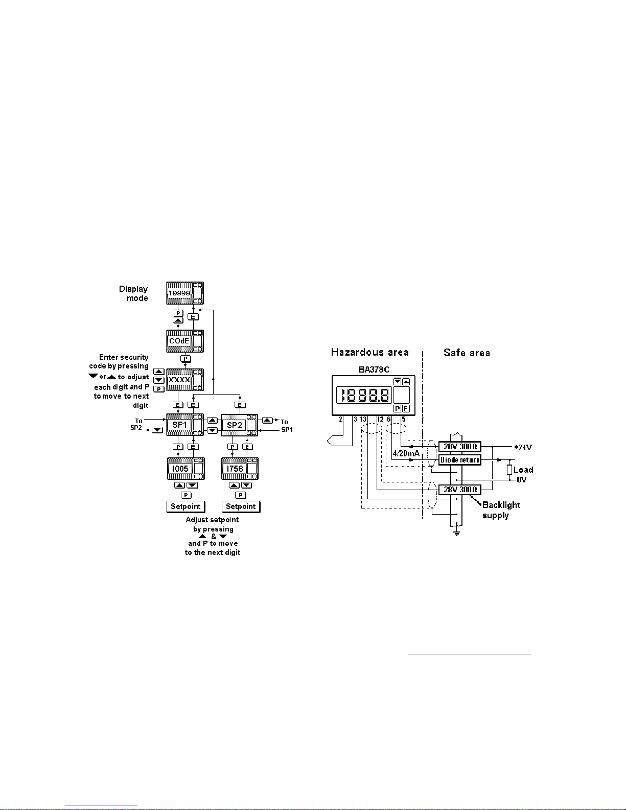
11.4 Adjusting the alarm setpoints from the
display mode.
Access to the alarm setpoint when the BA378C
transmitter is in the display mode is obtained by
operating the P and Up push-buttons simultaneously - see Fig 14. If the setpoints are not
protected by a security code the alarm setpoint one
'SP1' will be displayed. If the setpoints are
protected by a security code, 'COdE' will be
displayed first. Pressing P again will enable the
alarm security code to be entered digit by digit
using the Up and Down buttons to change the flashing digit, and the P push-button to move to the next
digit. If the correct code is entered pressing E will
cause alarm setpoint one 'SP1' to be displayed.
Pressing the Up or Down button will toggle the
display between 'SP1' and 'SP2'.
Fig 14 Setpoint adjustment from display mode
If an incorrect code is entered, or a button is not
pressed for ten seconds, the transmitter will
automatically return to the display mode.
To adjust an alarm setpoint select 'SP1' or 'SP2'
and press P which will reveal the current setting.
Each digit of the setpoint may be adjusted using the
Up and Down push-buttons, and the P button to
move to the next digit. When the required setpoint
has been entered, pressing E will return the
display to the 'SP1' or 'SP2' prompt from which the
other setpoint may be selected, or the transmitter
may be returned to the display mode by pressing E
again.
Direct access to the alarm setpoints is only available when the menu is enabled - see section 11.3.8
12. BACKLIGHT
The BA378C can be supplied with LED backlighting
to improve display contrast when the transmitter is
installed in a poorly illuminated area. This is
segregated from the measuring circuit and has
been certified as a separate intrinsically safe
circuit.
The backlight must be powered from the safe area
via a Zener barrier or a galvanic isolator as shown
in Fig 15. Any certified EEx ia IIC device may be
used, providing the output parameters do not
exceed:
Uo = 30V dc
Io = 159mA
Po = 0.85W
For guidance, the system certificates list some
devices which may be used.
Fig 15 Backlight power supply
The display brilliance depends upon the current
flowing through the backlight which is determined
by the supply voltage and the end-to-end resistance
of the Zener barrier or output resistance of the
galvanic isolator. Brilliance will not be significantly
reduced until the current falls below 20mA.
Backlight current = Vsupply -18
End-to-end resistance of barrier#
# or output resistance of galvanic isolator
27
 Loading...