

Page 1
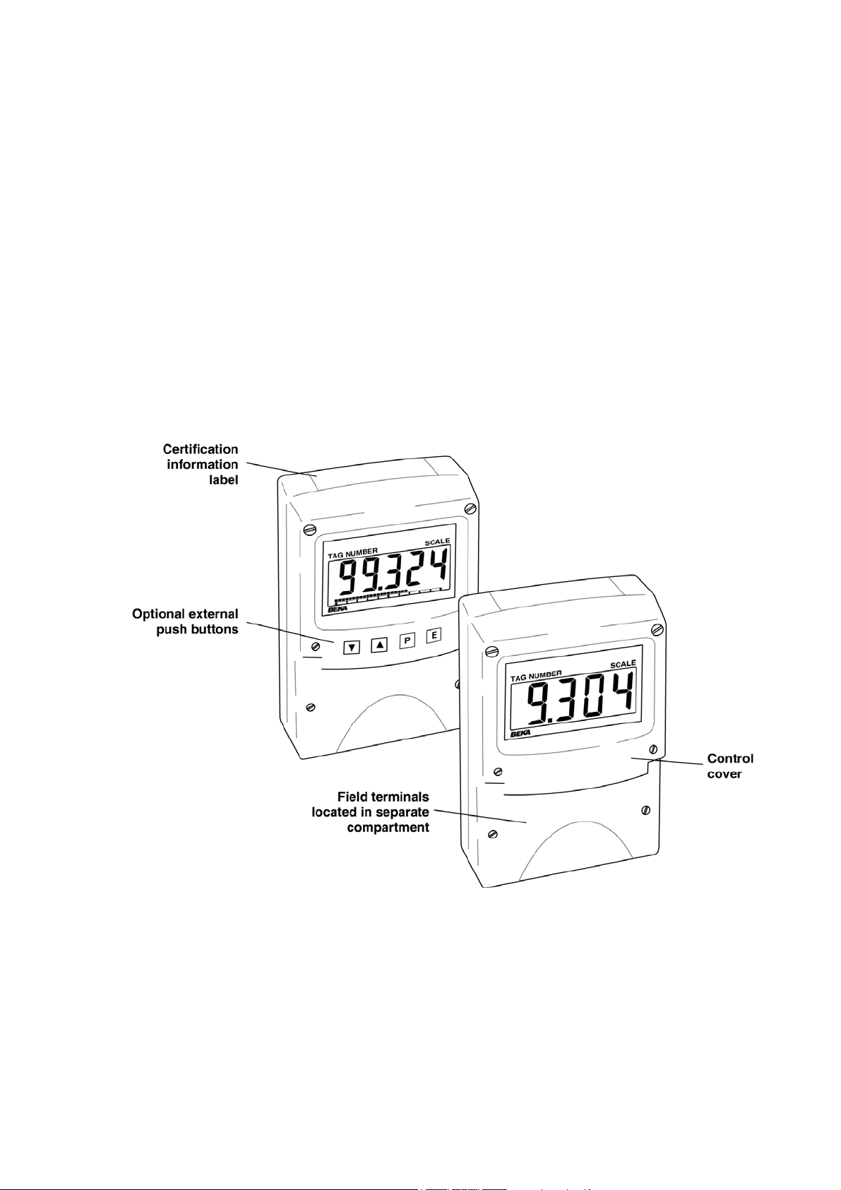
BA304NE & BA324NE
Type n
loop-powered
field mounting indicators
Issue 2
14
th
December 2011
Issue: 2
Page 2

2
CONTENTS
1. Description
2. Operation
2.1 Controls
3. Certification
3.1 ATEX Ex nA certification
3.2 Zones, gas groups & T rating
3.3 4/20mA input
3.4 Certification label information
4. System Design for Zone 2 Gas
Hazardous Areas
4.1 Transmitter loops
4.2 Remote indication
5. Installation
5.1 Location
5.2 Installation procedure
5.3 EMC
6. Configuration and Calibration
6.1 Summary of configuration
functions.
6.2 Indicator function
6.3 Resolution
6.4 Position of decimal point
6.5 Calibration using an external
current source.
6.6 Calibration using internal
reference.
6.7 Bargraph format and calibration
6.8 Function of the P push button
6.9 Tare function
6.10 Security code
6.11 Reset to factory defaults
6.12 Under and over-range
8. Maintenance
8.1 Fault finding during commissioning
8.2 Fault finding after commissioning
8.3 Servicing
8.4 Routine maintenance
8.5 Guarantee
8.6 Customer comments
9. Accessories
9.1 External keypad
9.2 Units of measurement and instrument
identification.
9.3 Alarms
9.3.1 Solid state output
9.3.2 Type nA certification
9.3.3 Configuration and adjustment.
9.3.4 Alarm enable
9.3.5 Setpoint adjustment
9.3.6 Alarm function
9.3.7 Alarm output status
9.3.8 Hysteresis
9.3.9 Alarm delay
9.3.10 Alarm silence time
9.3.11 Flash display when alarm
occurs.
9.3.12 Access setpoint in display
mode.
9.3.13 Adjusting alarm setpoint from
the display mode.
9.3.14 Displaying setpoints on
BA324NE bargraph.
9.4 Display backlight
9.4.1 Loop powering the backlight
9.4.2 Separately powering the
backlight.
9.5 Pipe mounting kits
7. Lineariser
Appendix 1 ATEX dust certification
7.1 Lineariser calibration using an external
current source.
Appendix 2 IECEx gas and dust certification
7.2 Lineariser calibration using internal
reference.
7.3 Lineariser error message
7.4 Under and over-range
7.5 Lineariser default configuration
The BA304NE & BA324NE are CE marked to show compliance with the European Explosive Atmospheres
Directive 94/9/EC and the European EMC Directive 2004/108/EC
Page 3
3
1. DESCRIPTION
These field mounting, Type nA certified, digital
indicators display the current flowing in a 4/20mA
loop in engineering units. They are loop powered
but only introduce a 1.2V drop, which allows them
to be installed into almost any 4/20mA current
loop. No additional power supply or battery is
required.
The two models are electrically similar, but have
different size displays.
Model Display
BA304NE 4 digits 15mm high
BA324NE 5 digits 11mm high and 31 segment
bargraph.
This instruction manual supplements the
instruction sheet supplied with each instrument.
The main application of both models is to display a
measured variable or control signal in a Zone 2
gas hazardous area or a Zone 22 dust hazardous
process area. The zero and span of the display
are independently adjustable so that the indicator
can be calibrated to display any variable
represented by the 4/20mA current, e.g.
temperature, flow, pressure or level.
2. OPERATION
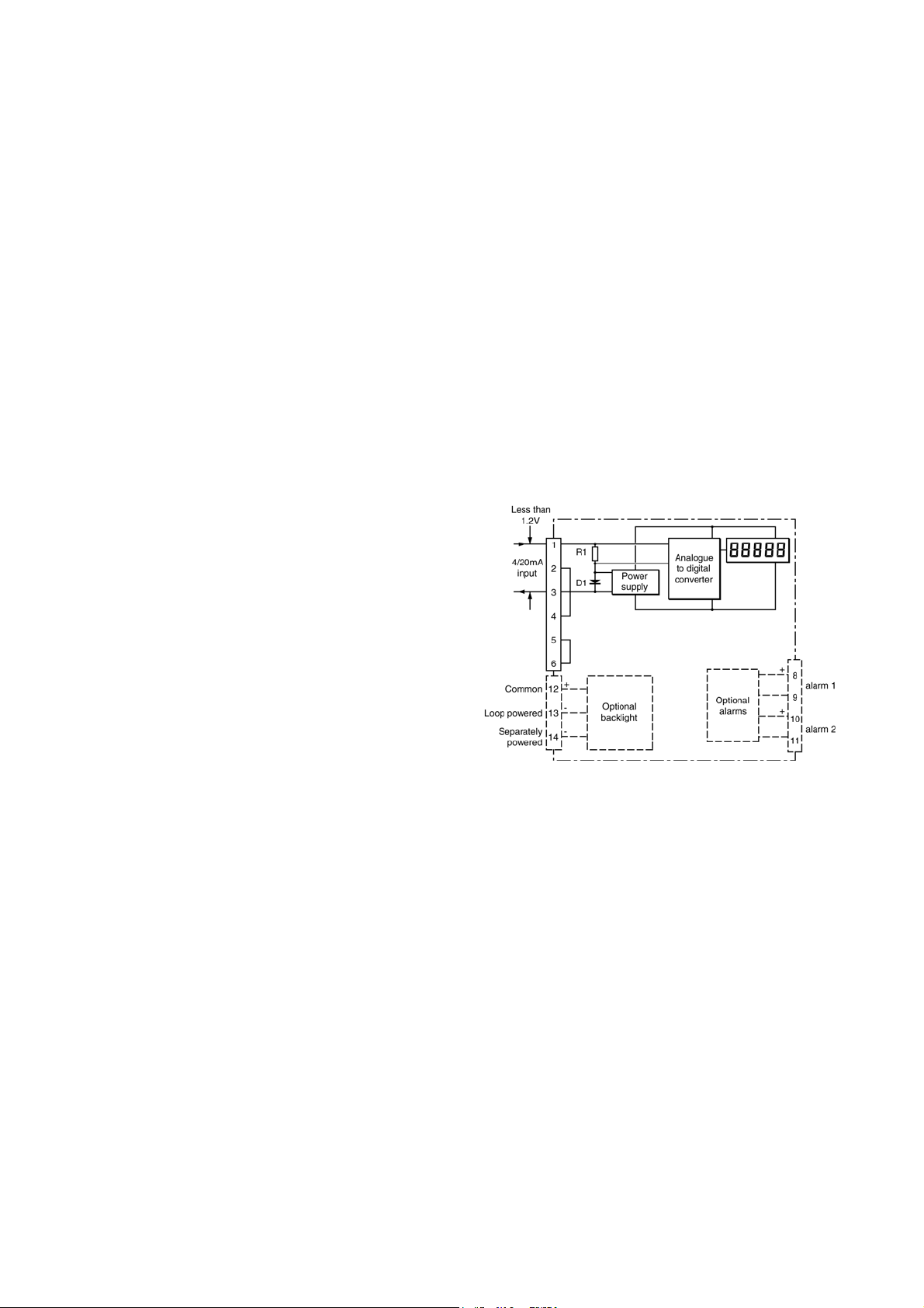
Fig 1 shows a simplified block diagram of both
models. The 4/20mA input current flows through
resistor R1 and forward biased diode D1. The
voltage developed across D1, which is relatively
constant, is multiplied by a switch mode power
supply and used to power the instrument. The
voltage developed across R1, which is proportional
to the 4/20mA input current, provides the input
signal for the analogue to digital converter.
Each time a 4/20mA current is applied to the
instrument, initialisation is performed during which
all segments of the display are activated, after five
seconds the instrument displays the input current
using the calibration information stored in the
instrument memory. If the loop current is too low
to power the instrument the indicator will display
the error message ‘LPLo’.
Both models have Ex nA and Ex tc certification
issued by Notified Body Intertek Testing and
Certification Ltd which has been used to confirm
complance with the European ATEX Directive
94/9/EC.
For international applications the two indicators
have IECEx certification which is described in
Appendix 2.
Fig 1 Indicator block diagram
Page 4

4
2.1 Controls
The indicators are controlled and calibrated via
four push button switches located behind the
instrument control cover, or as an option on the
control cover. In the display mode i.e. when the
indicator is displaying a process variable, these
push buttons have the following functions:
P While this button is pushed the
indicator will display the input current in
mA, or as a percentage of the
instrument span depending upon how
the indicator has been conditioned.
When the button is released the normal
display in engineering units will return.
The function of this push button is
modified when optional alarms are
fitted to the indicator.
▼ While this button is pushed the
indicator will display the numerical
value and analogue bargraph* the
indicator has been calibrated to display
with a 4mA
Φ
input. When released the
normal display in engineering units will
return.
3. CERTIFICATION
Both models have ATEX and IECEx gas and dust
certification. This section of the instruction manual
describes ATEX gas certification. ATEX dust
approval is described in Appendix 1 and IECEx
certification in Appendix 2.
3.1 ATEX Ex nA certification
Notified Body Intertek Testing and Certification Ltd
have issued both instruments with a common Type
Examination Certificate number ITS11ATEX47255.
This has been used to confirm compliance with the
European ATEX Directive for Group II, Category
3GD equipment. The indicators bear the
community mark and subject to local codes of
practice may be installed in any of the European
Economic Area (EEA) member countries. ATEX
certificates are also acceptable for installations in
Switzerland.
This section of the instruction manual describes
ATEX installations in explosive gas atmospheres
conforming with EN60079-14 Electrical
Installations in Hazardous Areas. When designing
systems for installation outside the UK the local
Code of Practice should be consulted.
▲ While this button is pushed the
indicator will display the numerical
value and analogue bargraph* the
indicator has been calibrated to display
with a 20mA
Φ
input. When released
the normal display in engineering units
will return.
E No function in the display mode unless
the tare function is being used.
P + ▼ Indicator displays firmware number
followed by version.
P + ▲ Provides direct access to the alarm
setpoints when optional alarms are
fitted to the indicator and the ‘ACSP’
access setpoints in display mode
function has been enabled.
P + E Provides access to the configuration
menu via optional security code.
Notes: * BA324NE only
Φ
If the indicator has been calibrated
using the CAL function, calibration
points may not be 4 and 20mA.
3.2 Zones, gas groups and T rating
The indicators have been certified as Group II
Category 3G Ex nA ic IIC T5 Gc apparatus with a
Ta of –40ºC to +70ºC. This is non-sparking
apparatus complying with EN 60079-15 that
minimises the risk of arcs or sparks capable of
creating an ignition hazard occurring during
conditions of normal operation.
The IEC guidance on maintenance procedures IEC
60079-17 permits live maintenance in Zone 2 if a
risk analysis demonstrates that this does not
introduce an unacceptable risk. The removal of
covers is permitted if this can be done without
contaminating the interior of the instrument with
dust or moisture. Since the relevant circuits are ‘ic’
[as indicated by the certificate] the adjustment and
calibration procedures listed in this document may
be carried out in Zone 2 or 22. Some end-users
may prefer not to permit live maintenance to
minimise risk.
Page 5
5
When connected to a suitable system the
indicators may be:
Installed in:
Zone 2 explosive gas air mixture not
likely to occur, and if it does
will only exist for a short time.
Be used with gases in groups:
Group A propane
Group B ethylene
Group C hydrogen
Having a temperature classification of:
T1 450
T2 300
T3 200
T4 135
T5 100
At ambient temperatures between -40 and +70
o
o
o
o
o
C
C
C
C
C
o
C.
This allows use with all industrial gases except
carbon disulphide CS
.
2
3.3 4/20mA input
The input safety parameters for the 4/20mA input,
terminals 1 and 3 are:
Ii = 100mA
4. SYSTEM DESIGN FOR ZONE 2 GAS
HAZARDOUS AREAS
4.1 Transmitter loops
Both models may be connected in series with
almost any Ex n protected 4/20mA current loop
and calibrated to display the measured variable or
control signal in engineering units. There are four
design requirements:
1. The current flowing in the 4/20mA loop, must
not exceed 100mA in normal operation.
2. Wiring must comply with Clause 9 of EN
60079-14 Electrical installation in hazardous
areas.
3. The instrument enclosure must be fitted with
Ex n or Ex e certified glands, conduit fittings
or blanking plugs.
4. The loop must be able to tolerate the
additional 1.2V required to operate the
indicator. This increases to 5.0V if the
indicator is fitted with an optional backlight
which is loop powered. See 9.4.1
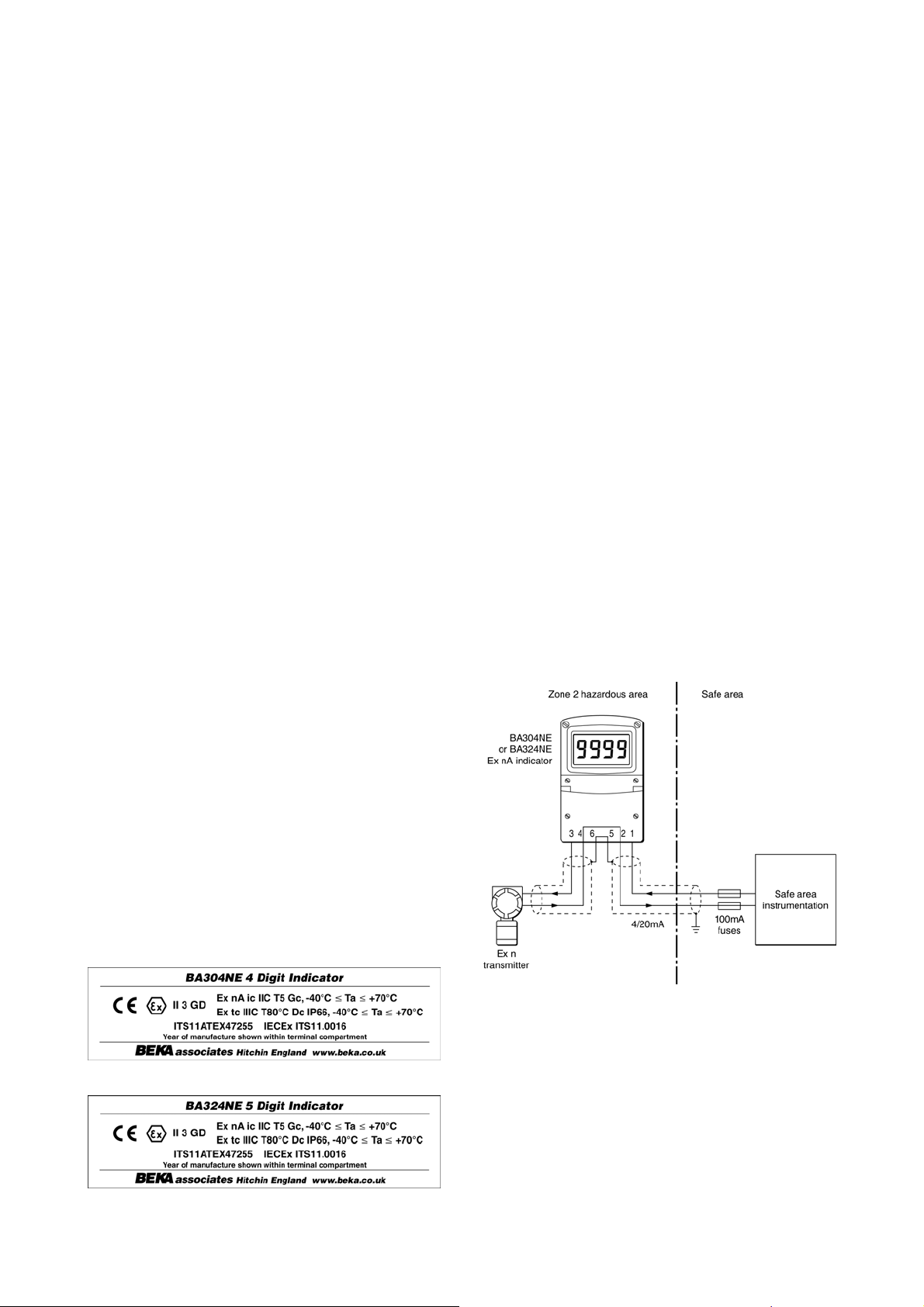
Figs 2 illustrate a typical application in which an
indicator is connected in series with a 2-wire Ex n
transmitter.
The indicators are current input instruments
incorporating an internal protection circuit that
defines the voltage developed between the input
terminals 1 and 3, therefore the ATEX certificate
does not specify a maximum safety input voltage
Ui.
3.4 Certification label information
The certification label is fitted in a recess on the
top outer surface of the instrument enclosure. It
shows the ATEX certification information and
BEKA associates' name and location. Non
European certification information may also be
shown. The instrument serial number and date of
manufacture are recorded on a separate label
inside the terminal compartment.
BA304NE certification label
BA324NE certification label
Fig 2 Typical Zone 2 transmitter loop
To strictly comply with the requirements of
EN 60079:14 Electrical installations design,
selection and erection, each of the wires entering
the hazardous area should be individually fused
and contain a means of isolation. However, in
practice instrumentation energised by a current
limited power supply or instrument that can be
switched off is often considered adequate.
Page 6
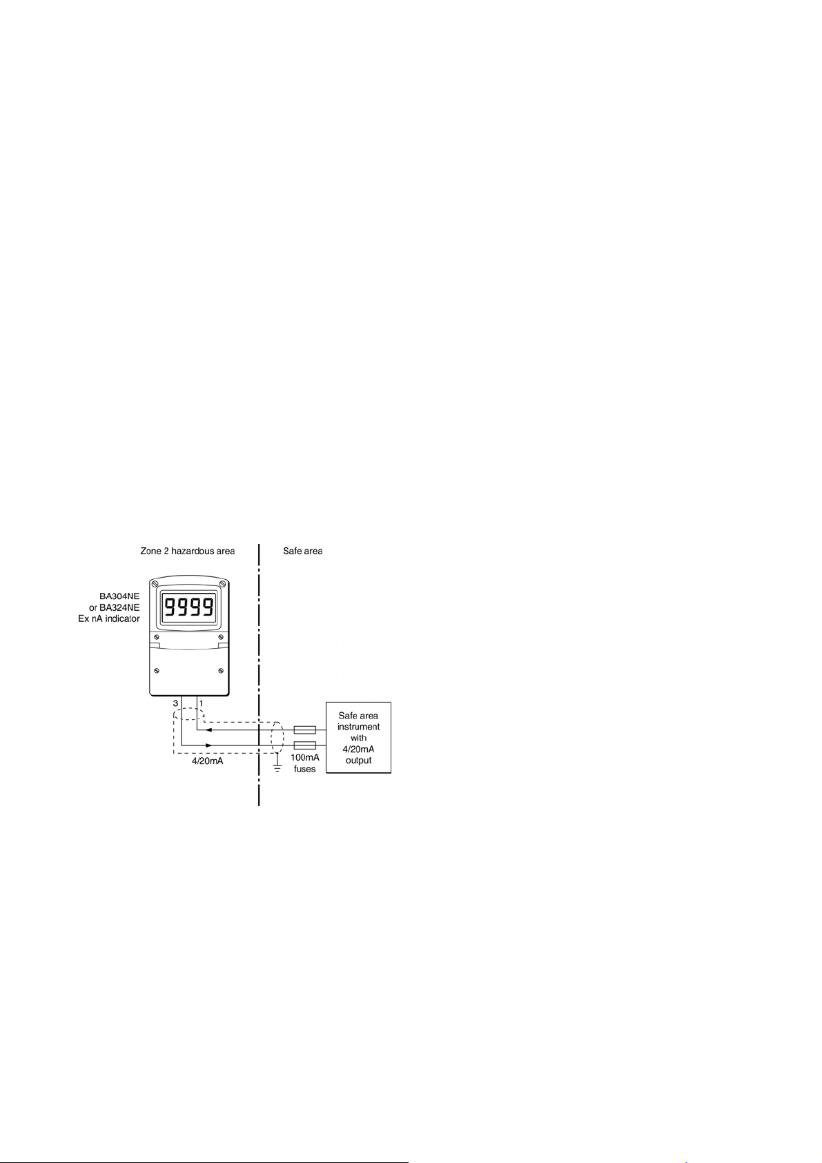
4.2 Remote indication
The BA304NE and the BA324NE may be driven
directly from a safe area instrument with a 4/20mA
output to provide a remote display within a Zone 2
hazardous area.
There are four design requirements:
1. The current flowing in the 4/20mA loop, must
not exceed 100mA in normal operation.
2. Wiring must comply with Clause 9 of
EN60079-14 Electrical installation in
hazardous areas.
3. The instrument enclosure must be fitted with
Ex n or Ex e certified glands, conduit fittings
or blanking plugs.
4. The safe area 4/20mA output from the safe
area instrument must be able to supply the
1.2V required to operate the indicator. This
increases to 5.0V if the indicator includes an
optional loop powered backlight. See 9.4.1
6
Fig 3 shows a typical application.
Fig 3 Remote indication in Zone 2 hazardous area
To strictly comply with the requirements of
EN 60079:14 Electrical Installation in Hazardous
Areas, each of the wires entering the hazardous
area should be individually fused and contain a
means of isolation. However, in practice
instrumentation energised by a current limited
power supply or instrument that can be switched
off is often considered adequate.
Page 7
5. INSTALLATION
5.1 Location
The BA304NE and BA324NE indicators are
housed in robust IP66 glass reinforced polyester
(GRP) enclosures incorporating an armoured glass
window and stainless steel fittings making them
suitable for exterior mounting in most industrial
installations, including off-shore and waste water
treatment. The indicator should be positioned
where the display is not in direct sunlight.
Both indicators are surface mounting, but may be
pipe mounted using one of the accessory kits
described in section 9.5 of this manual.
The field terminals and the two mounting holes are
located in a separate compartment with a sealed
cover allowing the instrument to be installed
without exposing the display assembly.
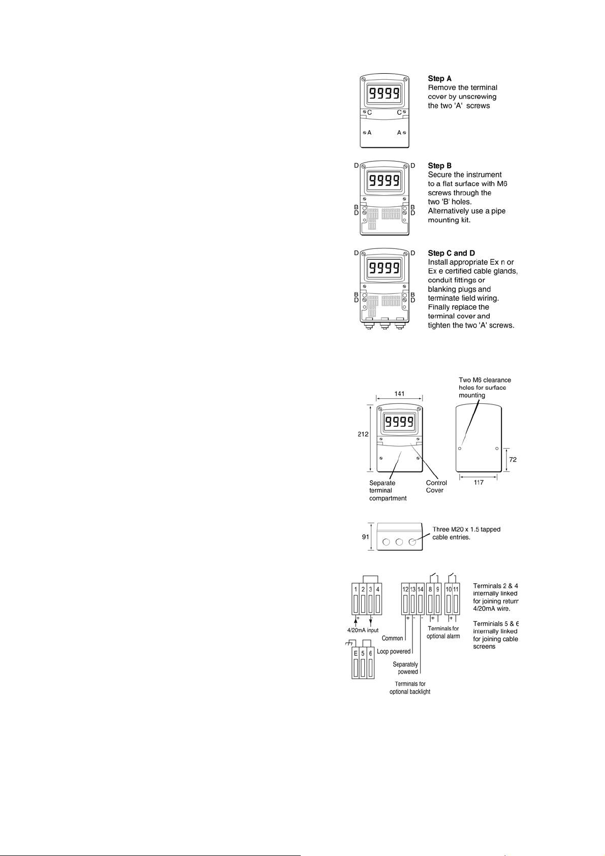
Terminals 2 and 4 are internally joined and may be
used for linking the return 4/20mA wire - see Fig 2.
Similarly terminals 5 and 6 are internally joined and
may be used for linking cable screens. The
indicator’s earth terminal is connected to the
carbon loaded GRP enclosure. If this enclosure is
not bolted to an earthed post or structure, the earth
terminal should be connected to the plant potential
equalising conductor.
7
Fig 4 BA304NE & BA324NE installation
procedure
The enclosures are fitted with a bonding plate to
ensure electrical continuity between the three
conduit / cable entries.
5.2 Installation Procedure
Fig 4 illustrates the instrument installation
procedure.
a. Remove the instrument terminal cover by
unscrewing the two captive 'A' screws.
b. Mount the instrument on a flat surface and
secure with screws or bolts through the two
'B' holes. Alternatively use one of the pipe or
stem mounting kits described in section 9.5.
c. Remove the temporary dust seals from the
three cable entries and install Ex n or Ex e
certified glands, conduit fittings or blanking
plugs.
Note: The temporary dust seals do not
provide IP66 protection and must not be
used in Zone 2.
d. Connect the field wiring to the terminals as
shown in Fig 5.
e. Replace the instrument terminal cover and
evenly tighten the two 'A' screws.
Fig 5 Dimensions and terminal connections
5.3 EMC
Both instruments compy with the requirements of
the European EMC Directive 2004/108/EC. For
specified immunity all wiring should be in screened
twisted pairs, with the screens earthed in the safe
area.
Page 8

8
6. CONFIGURATION AND CALIBRATION
Both indicators are configured and calibrated via
four push buttons which are located behind the
control cover. An optional external keypad
mounted on the outside of the control cover allows
the indicator to be configured live without removing
the cover. All the configuration functions are
contained in an easy to use intuitive menu that is
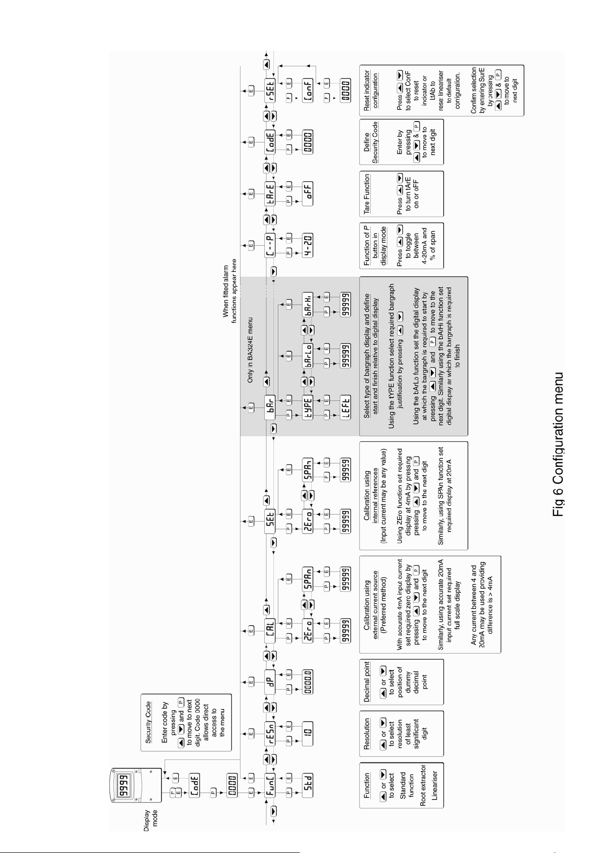
shown diagrammatically in Fig 6.
Each menu function is summarised in section 6.1
and includes a reference to more detailed
information. When the indicator is fitted with alarms
additional functions are added to the menu which
are described in section 9.3 Throughout this
manual push buttons are shown as P, E, ▼ or ▲,
and legends displayed by the indicator are shown
within inverted commas e.g. 'CAL' and ' ALr2'.
Access to the configuration menu is obtained by
operating the P and E push buttons
simultaneously. If the indicator security code is set
to the default 0000 the first parameter 'FunC' will
be displayed. If a security code other than the
default code 0000 has already been entered, the
indicator will display 'CodE'. Pressing the P button
will clear this prompt allowing each digit of the
code to be entered using the ▲ and ▼ push
buttons and the P button to move control to the
next digit. When the correct four digit code has
been entered pressing E will cause the first
parameter 'FunC' to be displayed. If the code is
incorrect, or a button is not pressed within twenty
seconds, the indicator will automatically return to
the display mode.
Once within the configuration menu the required
parameter can be reached by scrolling through the
menu using the ▲ and ▼ push buttons as shown
in Fig 6. When returning to the display mode
following recalibration or a change to any function,
the indicator will display ‘dAtA’ followed by ‘SAVE’
while the new information is stored in non-volatile
memory.
All new indicators are supplied calibrated as
requested at the time of ordering. If calibration is
not requested, indicators will be supplied with the
following default configuration:
6.1 Summary of configuration functions
This section summarises each of the main
configuration functions and includes a cross
reference to a more detailed description. Fig 6
illustrates the location of each function within the
configuration menu. The lineariser and the
optional factory fitted alarms are described
separately in sections 7 and 9.3 of this manual.
Display Summary of function
'FunC' Indicator function
Defines the relationship between the
4/20mA input current and the indicator
display. May be set to:
‘Std’ Standard linear relationship
‘root’ Square root extraction
‘Lin’ 16 segment adjustable
lineariser – see section 7.
See section 6.2
'rESn' Display resolution
Defines the resolution of the least
significant display digit. May be set to
‘1’, ‘2’, ‘5’ or ‘10’ digits.
See section 6.3
'dP' Decimal point
Positions a dummy decimal point
between any of the digits or turns it off.
See section 6.4
'CAL' Calibration of the digital display
using an external current source.
Enables the zero and span of the
indicator to be adjusted using an
external current source such as a
calibrator. When used with an accurate
traceable current source this is the
preferred method of calibration.
See section 6.5
'SEt' Calibration of display using internal
references.
Enables the zero and span of the
indicator to be adjusted without the
need for an accurate input current or
disconnection from the 4/20mA loop.
See section 6.6
Default Configuration
BA304NE BA324NE
Access code ‘CodE’ 0000 0000
Function ‘FunC’ Linear Linear
Display at 4mA ‘Zero’ 0.0 0.00
Display at 20mA ‘SPAn’ 100.0 100.00
Resolution ‘rESn’ 1 digit 1 digit
Bargraph start ‘BarLo’ ----- 0.00
Bargraph finish ‘BarHi’ ----- 100.00
P button in display mode ‘C-P’ % %
Tare ‘tArE’ Off Off
'bAr' Bargraph format and claibration
Only the BA324NE has a bargraph
The bargraph may be conditioned to
start from left, right or centre of the
display, or it may be disabled. When
optional alarms are fitted it can also
display both alarm setpoints and the
measured value.
The bargraph may be calibrated to start
and finish at any value within the
indicator’s calibrated digital display.
See section 6.7
Page 9
9
Page 10

10
Display Summary of function
'C - - P' Function of P push button
The indicator may be configured to
display the input current in milliamps, or
the input current as a percentage of the
4/20mA input when the P push button
is operated in the display mode.
See section 6.8
'tArE' Tare function
When enabled the tare function sets
the indicator display to zero when the E
push button is operated in the display
mode.
See section 6.9
'CodE' Security code
Defines a four digit numeric code that
must be entered to gain access to the
configuration menu. Default code 0000
disables this security function and
allows unrestricted access to all
conditioning functions.
See section 6.10
'rSEt' Reset
Contains two sub-functions, ‘ConF’
which returns the indicator to the
default conditions shown in section 6.0
and ‘LtAb’ which returns the lineariser
to the default conditions shown in
section 7.3. To prevent accidental use
both resets must be confirmed by
entering ‘5urE’ before they will be
executed.
See section 6.11
6.2 Indicator function: ‘FunC’
This configuration function defines the relationship
between the indicator’s 4/20mA input current and
the indicator’s display. Three alternatives are
available:
‘Std’ Standard linear relationship
‘root’ Square root extraction
‘Lin’ 16 segment adjustable lineariser
To reveal the existing indicator function select
'FunC' from the configuration menu and press P.
If the function is set as required, press E to return
to the menu, or press the ▲ or ▼ button to change
the setting, followed by the E button to return to the
configuration menu.
‘Std’ Linear
Provides a linear relationship between the
4/20mA indicator input current and the
indicator display.
‘root’ Square root extraction
Primarily intended to linearise the square
law 4/20mA output from differential
flowmeters.
For reference, the following table shows
the output current from a non-linearised
differential flowmeter.
% of full flow Current output mA
2.5 4.01
10.0 4.16
25.0 5.00
50.0 8.00
75.0 13.00
100.0 20.00
When the root function is selected the
indicator will display flow in linear units.
‘Lin’ 16 segment adjustable lineariser
Enables non linear variables to be
displayed by the indicator in linear
engineering units. Use of the lineariser is
described in section 7 of this instruction
manual.
6.3 Resolution: rESn
This function defines the resolution of the least
significant display digit. Decreasing the display
resolution can improve the readability of a noisy
signal. Select ''rESn' from the menu and press P
which will reveal the current display resolution. To
change the resolution press the ▲ or ▼ button to
select 1, 2, 5 or 10 digits, followed by the E button
to enter the selection and return to the
configuration menu.
Page 11

11
6.4 Position of the decimal point: ‘dP’
A dummy decimal point can be positioned between
any of the digits or it may be absent. To position
the decimal point select 'dP' from the menu and
press P. The decimal point can be moved by
pressing the ▲ or ▼ push button. If a decimal
point is not required it should be positioned beyond
the most or least significant digit. When
positioned as required press the E button to enter
the selection and return to the configuration menu.
6.5 Calibration using an external
current source: ‘CAL’
This function enables the zero and span of the
indicator to be adjusted using an external
calibrated current source. When used with an
accurate traceable current source this is the
preferred method of calibration.
Zero is the indicator display with 4mA input
Span is the indicator display with 20mA input
To calibrate the indicator select 'CAL' from the
configuration menu and press P. The indicator will
display 'ZEro' which is a request for a 4mA input
current. Adjust the external current calibrator to
4.000mA and again press P which will reveal the
current zero display. The flashing digit of the
indicator display can be changed by pressing the
▲ or ▼ buttons, when set as required pressing P
will transfer control to the next digit. When all the
digits have been adjusted, press E to enter the
new zero and return to the 'ZEro' prompt .
Pressing the ▲ button will cause the indicator to
display 'SPAn' which is a request for a 20mA input
current. Adjust the external current calibrator to
20.000mA and again press P which will reveal the
existing span display. The flashing digit of the
indicator display can be changed by pressing the
▲ or ▼ buttons, when set s required pressing P
will transfer control to the next digit. When all the
digits have been adjusted press E to enter the new
span and return to the 'SPAn' prompt. Finally
press E again to return to the configuration menu.
Notes:
a. The indicator input current must be adjusted to
the required value before the zero and span
functions are entered by pressing the P button.
6.6 Calibration using internal reference:
‘SEt’
Using the ‘SEt’ function the indicator can be
calibrated without the need to know the value of
the 4/20mA input current, or to disconnect the
indicator from the 4/20mA loop.
When using the ‘Set’ function the indicator’s
internal reference is used to simulate a 4mA and
20mA input current.
Zero is the display with a simulated 4mA input
Span is the display with a simulated 20mA input
To calibrate the indicator display select 'SEt' from
the configuration menu and press P. The indicator
will display 'ZEro', pressing
P again will reveal the
current display at 4mA. The flashing digit can be
adjusted by pressing the ▲ or ▼ buttons, when
the flashing digit is correct pressing P will transfer
control to the next digit. When all the digits have
been adjusted, press E to return to the 'ZEro'
prompt.
To adjust the display at 20mA, press the ▲ button
which will cause the indicator to display 'SPAn',
pressing P will then reveal the indicator’s existing
display at 20mA. The flashing digit can be
adjusted by pressing the ▲ or ▼ buttons, when
the flashing digit is correct pressing P will transfer
control to the next digit. When all the digits have
been adjusted press E to return to the 'SPAn'
prompt followed by E to return to the ‘SEt’ prompt
in the configuration menu.
6.7 Bargraph format and calibration: ‘bAr’
Only the BA324NE has a bargraph
In addition to a five digit numerical display the
BA324NE has a 31 segment analogue bargraph
which may be configured to start and finish
anywhere within the indicator’s numerical display
range.
To configure the bargraph select 'bAr' from the
configuration menu and press P. The indicator will
display 'tYPE', pressing P again will reveal the
existing bargraph justification which can be
changed to one of the following four or five options
using the ▲ or ▼ button:
b. Indicators may be calibrated at currents other
than 4 and 20mA, withiin the range 3.8 to
21.0mA providing the difference between the
two currents is greater than 4mA. If these
conditions are not complied with, the indicator
displays ‘FaiL’ and aborts the calibration.
c. If the zero current is greater than the span
current the instrument will be reverse acting
i.e. an increasing input current will cause the
display to decrease.
Bargraph justification starts from
‘LEFt’ Left end of display
‘CEntr’ Centre of display
‘riGHT’ Right end of display
‘AlrSP’ Only with alarms – see section 9.3
‘oFF’ Bargraph disabled
When set as required press E to return to the
‘tYPE’ sub-function prompt.
Page 12

12
The indicator’s digital display at which the
bargraph starts is defined by the ‘bArLo’ subfunction which is selected by pressing the ▲
button followed by the P button which will reveal
the current indicator display at which the bargraph
starts. The flashing digit can be adjusted by
pressing the ▲ or ▼ buttons, when set as required
pressing P will transfer control to the next digit.
When all the digits have been adjusted, press E to
return to the 'bArLo' prompt from which ‘bArHi’
which defines the finishing point of the bargraph
can be selected by pressing the ▲ button. ‘bArHi’
is adjusted in the same way as ‘bArLo’. When set
as required, pressing E twice will return the display
to the ‘bAr’ prompt in the configuration menu.
Note: ‘bArLo’ must be set lower than ‘bArHi’,
incorrect setting is indicated by the bargraph scale
flashing with a single bargraph segment activated.
6.8 Function of the P push button: ‘C - - P’
When the indicator is in the display mode,
operating the P push button will display the input
current in milliamps, or the displayed value as a
percentage of the difference between the
displayed values at 4mA and 20mA inputs.
To check or change the function of the P push
button select 'C - -P' from the configuration menu
and press P to reveal the current setting. Pressing
the ▲ or ▼ button will toggle the setting between
'4-20' the current display in milliamps and 'PC' the
percentage display. When set as required press
E to return to the ‘C - - P’ prompt in the
configuration menu.
6.9 Tare function: ‘tArE’
The tare function is primarily intended for use with
weighing system. When the indicator is in the
display mode and the tare function is activated,
pressing the E button for more than three seconds
will zero the indicator display and activate the tare
annunciator. Subsequent operation of the E push
button for less than 3 seconds will return the
indicator to the gross display and deactivate the
tare annunciator.
To check or change the tare function select 'tARE'
from the configuration menu and press P to reveal
the current setting. Pressing the ▲ or ▼ button
will toggle the setting between 'on' and 'oFF'.
When set as required press E to return to the
‘tARE’ prompt in the configuration menu.
6.10 Security code: ‘CodE’
Access to the instrument configuration menu may
be protected by a four digit security code which
must be entered to gain access. New instruments
are configured with the default security code 0000
which allows unrestricted access to all
configuration functions.
To enter a new security code select 'CodE' from
the configuration menu and press P which will
cause the indicator to display the existing security
code with one digit flashing. The flashing digit can
be adjusted using the
▲ and ▼ push buttons,
when set as required operating the P button will
transfer control to the next digit. When all the
digits have been adjusted press E to return to the
‘CodE’ prompt in the configuration menu. The
revised security code will be activated when the
indicator is returned to the display mode.
Please contact BEKA associates sales department
if the security code is lost.
6.11 Reset to factory defaults: ‘rSEt’
This function enables the indicator and the
lineariser to be quickly returned to the factory
default configurations shown in sections 6.0 and
7.3
To reset the indicator or lineariser select ‘rSEt’
from the configuration menu and press P, the
indicator will display one of the reset options
‘ConF’ or ‘LtAb’.
‘ConF’ Resets the indicator to defaults
‘LtAb’ Resets the lineariser to defaults
Using the ▲ or ▼ push button select the required
sub-function and press P. To prevent accidental
resetting the request must be confirmed by
entering ‘5urE’. Using the ▲ button set the first
flashing digit to ‘5’ and press P to transfer control
to the second digit which should be set to ‘u’.
When ‘5urE’ has been entered pressing the E
button will reset the selected configuration menus
and return the display to the ‘rSEt’ function in the
configuration menu.
6.12 Under and over-range
If the numerical display range of the indicator is
exceeded, all the decimal points will flash as
shown below:
BA304NE BA324NE
Underrange -9.9.9.9 -9.9.9.9.9
Overrange 9.9.9.9 9.9.9.9.9
Although not guaranteed, most indicators will
continue to function normally with an input current
between 1.8mA and 4mA, at lower currents the
instrument will display ‘LPLo’ before it stops
functioning.
Under or overrange of the BA324NE bargraph is
indicated by an activated arrow at the appropriate
end of the bargraph and a flashing bargraph scale.
Page 13
13
7. LINEARISER
A sixteen segment, seventeen breakpoint (0 to 16)
lineariser may be selected in the ‘FunC’ section of
the configuration menu. The starting point and
slope of each straight line segment are fully
adjustable allowing the indicator to display most
non-linear process variables in linear engineering
units. Each break-points must occur at a current
greater than the preceeding break-point and less
than the following break-point, in the range 3.8 to
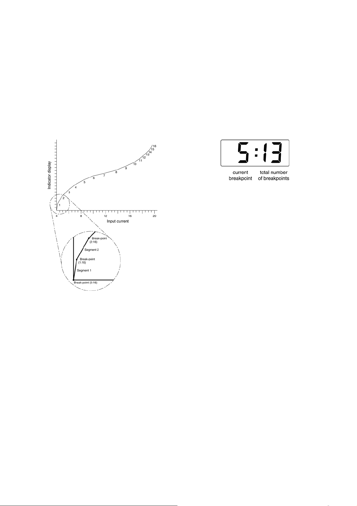
21.0mA Fig 8 shows a typical linearised indicator
characteristic. Fig 7 shows a typical linearised
indicator characteristic.
variable to be displayed. e.g. the output from a
level sensor in an irregular tank may be displayed
in linear volumetric units by filling the tank with
known incremental volumes and calibrating the
indicator to display the sum of the increments at
each break-point.
The number of break-point required should first be
entered using the 'Add' and 'dEL' functions. In
both these sub-functions the indicator initially
displays the current break-point and the total
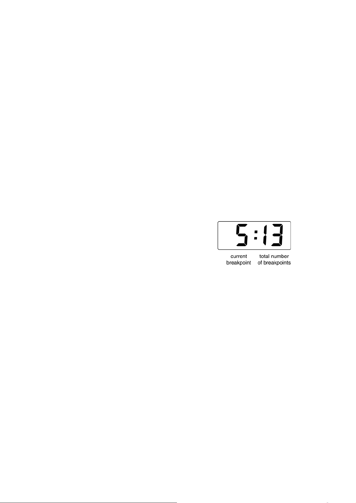
number of break-points being used as shown
below.
Display Description of function
'Add' Add a break-point
Adds a new break-point before the
displayed break-point. The calibration
of existing break-points is not changed,
but the identification number of all
subsequent break-points is increased
by one.
Fig 7 shows a typical linearising characteristic
Selecting ‘Lin’ in the ‘FunC’ section of the
configuration menu activates the lineariser, this
does not change the configuration menu shown in
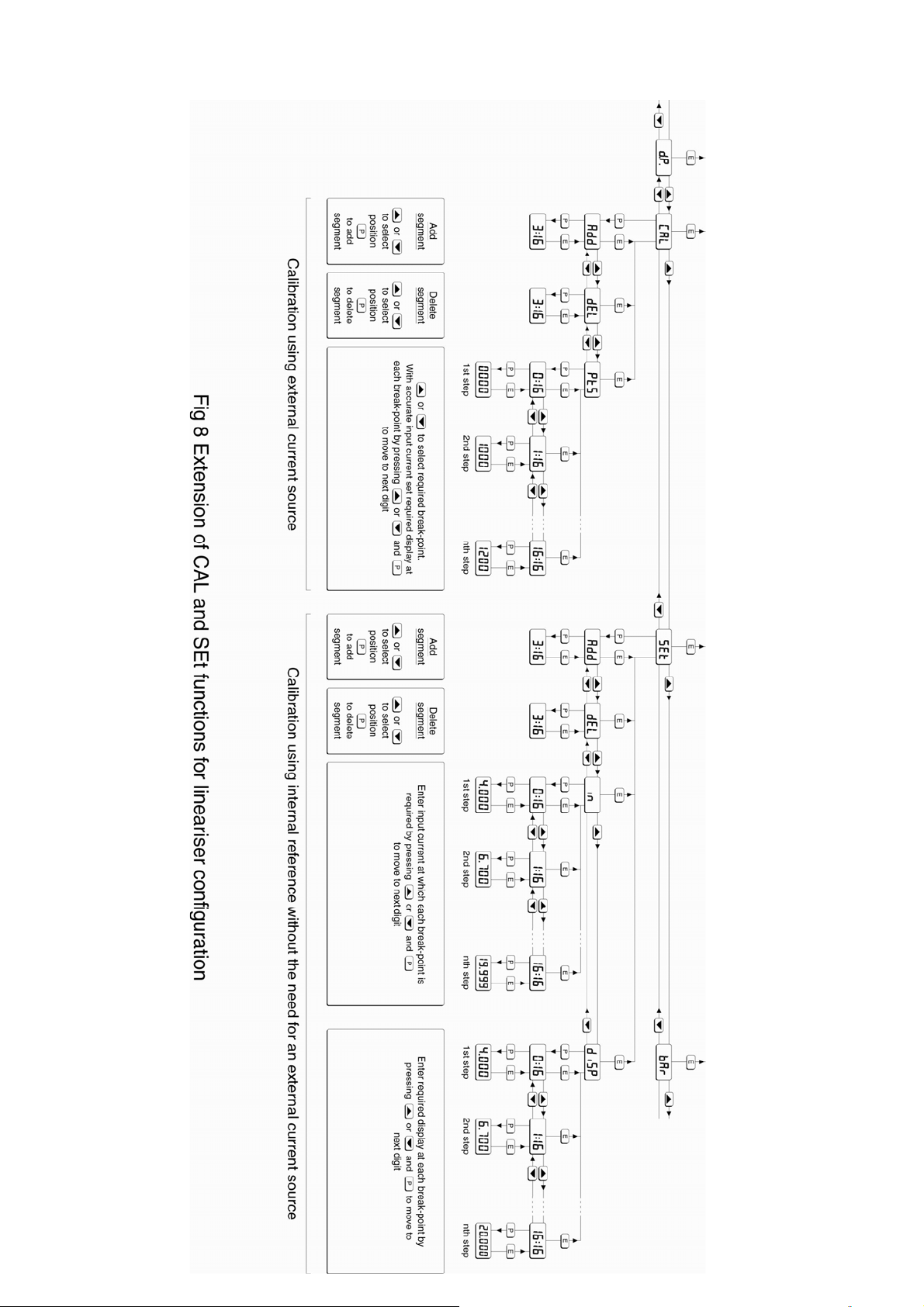
Fig 6, but the 'CAL' and 'SEt' functions are
extended as shown in Fig 8. As with a linear
indicator, calibration may be performed with an
external current source using the 'CAL' function, or
with the internal reference using the 'SEt' function.
The lineariser configuration is retained irrespective
of how the the indicator function ‘FunC’ is
subsequently changed. It is therefore possible to
select and deselect the lineariser without having to
reconfigure it each time.
7.1 Lineariser calibration using an external
current source.
This method allows direct calibration of the
lineariser with an exteral current source and is the
preferred method when traceability is required. If
the exact system non-linearity is unknown, this
method also allows direct calibration from the
'dEL' Remove a break-point
Removes the displayed break-point and
joins the preceding break-point to the
following break-point with a straight
line. The identification number of all
subsequent break-points is decreased
by one.
To add a break-point use the ▲ or ▼ button to
select 'CAL' from the configuration menu and press
P which will result in the 'Add' sub-function prompt
being displayed. To enter the sub-function press P
which will reveal the current break-point and the
total number of break-points which have already
been entered. Each subsequent operation of the
P push button will introduce an additional breakpoint up to the maximum of 17. When adding a
break-point to a calibrated indicator, the insertion
position for the new segment can be selected
using the ▲ and ▼ push buttons.
The delete break-point sub-function 'dEL' operates
in exactly the same way as the 'Add' sub-function
described above. Once within the ‘dEL’ subfunction each time the P button is pressed a breakpoint is removed. When deleting a break-point
from a calibrated indicator, the break-point to be
deleted can be selected using the ▲ and ▼ push
buttons. The minimum number of break-point is 2,
break-points 0 and 1.
Page 14
14
Page 15
15
When the required number of linearising breakpoints have been entered, return to the
linearisation sub-menu by pressing E. The
indicator will display the 'Add' or 'dEL' prompt
depending upon the last function used. The breakpoint of each segment, which is its finishing point,
as shown in Fig 7, can now be defined using the
‘Pts’ sub-function.
Using the ▲ or ▼ button select 'PtS' from the submenu and press P which will select the starting
point for the first segment '0 : n', where n is the
total number of linearising break-points entered.
The selected linearising break-point can be
changed using the ▲ and ▼ buttons. When the
required linearising break-point has been selected
set the indicator input current to the exact value at
which the break-point is required and press P.
Using the ▲ and ▼ buttons and the P button to
move between digits, enter the required indicator
display at this break-point.
When set as required, press the E push button to
enter the required indicator display and return to
the sub-menu from which the next beak-point can
be selected.
'dEL' Remove a break-point
Removes the displayed break-point
and joins the preceding segment to the
following segment with a straight line.
The identification number of all
subsequent break-points is decreased
by one.
'in' Defines the current at which break-
point occurs.
Enables the required current at each
break-point to be defined without
having to input an accurate input
current to the indicator.
'diSP' Defines indicator display at break-
point.
Enables the indicator display at each
break-point to be defined.
The number of break-point required should first be
entered using the 'Add' and 'dEL' sub-functions.
In both these sub-functions the indicator initially
displays the current break-point and the total
number of break-point being used as shown below.
When all the break-points have been calibrated
pressing E twice will return the indicator to the
‘CAL’ function in the configuration menu.
Note: The indicator input current must be adjusted
to the required value before the P button is
operated to enter the required indicator display.
7.2 Lineariser calibration using the internal
reference.
The ‘SEt’ function enables the lineariser to be
calibrated without the need for an accurate
external current source. Throughout the
calibration the indicator input current may be any
value between 4 and 20mA.
The ‘SEt’ functions contains four sub-functions.
Display Description of function
'Add' Add a break-point
Adds a new break-point before the
displayed break-point. The calibration
of existing break-points is not changed,
but the identification number of all
subsequent break-point is increased by
one.
To add a break-point using the ▲ or ▼ button
select 'SEt' from the configuration menu and press
P which will result in the 'Add' sub-function prompt
being displayed. To enter the sub-function press P
which will reveal the current break-point and the
total number of break-point which have already
been entered. Each subsequent operation of the
P push button will introduce an additional breakpoint up to the maximum of 17. When adding a
break-point to a calibrated indicator, the insertion
position for the new segment can be selected
using the ▲ and ▼ push buttons.
The delete break-point, sub-function 'dEL' operates
in exactly the same way as the 'Add' sub-function
described above. Once within the ‘dEL’ function
each time the P button is pressed a break-point is
removed. When deleting a break-point from a
calibrated indicator, the break-point to be deleted
can be selected using the ▲ and ▼ push buttons.
The minimum number of break-point is 2, breakpoints 0 and 1.
Page 16

16
When the required number of linearising breakpoint has been entered, return to the linearisation
sub-menu by pressing E. The indicator will display
the 'Add' or 'dEL' prompt depending upon the last
sub-function used. The indicator input current and
corresponding indicator display at each breakpoint, which is the segment finishing point as
shown in Fig 8, can now be entered using the ‘in’
and ‘diSP’ sub-functions.
Using the ▲ or ▼ button select 'in' from the submenu and press P which will reveal the starting
point for the first segment '0 : n', where n is the
total number of break-point entered. Press P and
use the ▲ and ▼ buttons and the P button to
move between digits, to enter the input current at
which the first break-point is required, usually
4.000mA. When set as required, press E to return
to the ‘0 : n’ prompt from which the the next
break-point can be selected using the ▲ and ▼
buttons. When the required break-point has been
selected press P and set the indicator input current
at this break-point. Repeat this procedure until the
indicator input current at all the the break-points
has been defined and then return to the ‘in’ subfunction by pressing the E button.
7.4 Under and over-range
The lineariser does not change the under and
over-range indication described in section 6.12.
At input currents below that specified for the first
break-point (0), the indicator will continue to use
the specified slope of the first segment. Although
not guaranteed, most indicators will continue to
function normally with an input current between
1.8mA and 4mA, at lower currents the instrument
will display ‘LPLo’ before it stops functioning.
At input currents above that specified for the last
break-point, the indicator will continue to use the
slope specified for the last lineariser segment.
7.5 Lineariser default configuration
When the lineariser is reset to the default
conditions using the ‘rSEt’ reset function described
in section 6.11, the defaults conditions are:
BA304NE BA324NE
First break-point 4mA 0.0 0.00
Second break-point 20mA 100.0 100.00
The corresponding indicator display at each of the
break-points can now be defined using the ‘diSP’
sub-function Using the ▲ and ▼ buttons select
the ‘diSP’ sub-function and press P which will
reveal the starting point for the first break-point
'0 : n', where n is the total number of break-points
entered. Press P and use the ▲ and ▼ buttons
and the P button to move between digits, to enter
the required indicator display at the first breakpoint. When set as required, press E to return to
the ‘0 : n’ prompt from which the the next breakpoint can be selected using the ▲ or ▼ buttons.
When the required break-point has been selected
press P and set the required indicator display at
this break-point.
Repeat this procedure until the indicator display at
all the break-points has been defined and then
return to the ‘SEt’ function in the configuration
menu by pressing the E button twice.
7.3 Lineariser error message
If an attempt is made to position a break-point at a
current which is not greater than the current of the
preceeding break-point, or at a current which is not
less than the current of the following break-point,
the error message ‘FaiL’ will be displayed. This
error message will also be displayed if an attemp[t
is made to position a break-point outside the
current range 3.8 to 21.0mA.
Page 17
17
8. MAINTENANCE
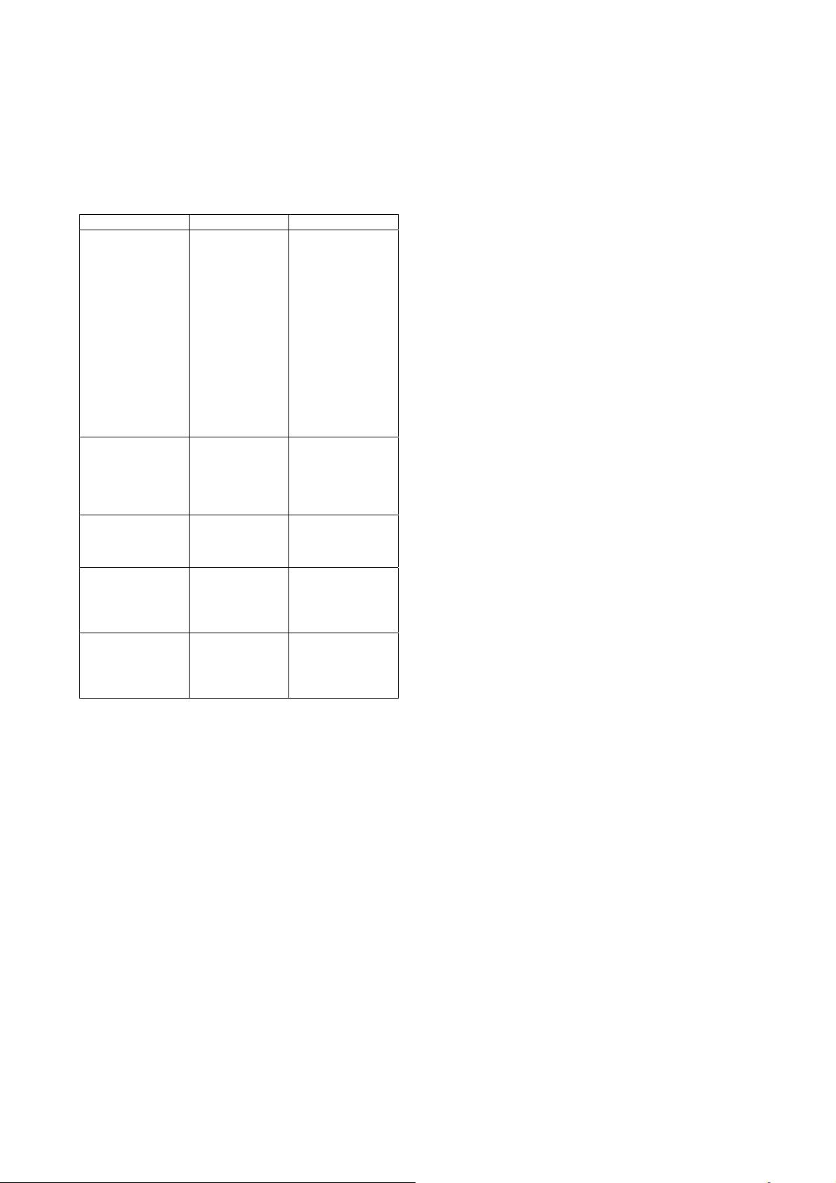
8.1 Fault finding during commissioning
If an indicator fails to function during
commissioning the following procedure should be
followed:
Symptom Cause Solution
No display Incorrect wiring Check wiring
There should be
0.6 to 1.2V
between terminals
1 & 3 with terminal
1 positive.
With an optional
loop powered
backlight, there
should be 3.4 to
5V between
terminals 1 & 13
with terminal 1
No display
0V between
terminals 1 & 3.
All decimal points
flashing.
Unstable display 4/20mA input is
Unable to enter
configuration
menu.
Incorrect wiring
or no power
supply
Underrange if
–ve sign
displayed or
overrange.
noisy.
Incorrect
security code
entered.
positive.
Check supply
voltage and
voltage drop
caused by all the
instruments in the
loop.
Recalibrate the
numerical display.
Eliminate ripple on
4/20mA power
supply and/or
decrease indicator
resolution.
Enter correct
security code, or
contact BEKA if
the code has been
lost.
8.2 Fault finding after commissioning
ENSURE PLANT SAFETY BEFORE
STARTING MAINTENANCE
If an indicator fails after it has been functioning
correctly follow the procedure shown in section
8.1. If this does not reveal the cause of the fault, it
is recommended that the instrument is replaced.
8.3 Servicing
All BA304NE and BA324NE loop powered
indicators are interchangeable if the required
optional backlight and alarms are fitted. A single
spare instrument may quickly be recalibrated to
replace any instrument that is damaged or fails.
No attempt should be made to repair instruments
at component level.
We recommend that faulty instruments
are returned to BEKA associates or to
your local BEKA agent for repair.
8.4 Routine maintenance
The mechanical condition of the instrument and
electrical calibration should be regularly checked.
The interval between inspections depends upon
environmental conditions. We recommend that
initially instrument calibration should be checked
annually.
8.5 Guarantee
Indicators which fail within the guarantee period
should be returned to BEKA associates or our local
agent. It is helpful if a brief description of the fault
symptoms is provided.
8.6 Customer comments
BEKA associates is always pleased to receive
comments from customers about our products and
services. All communications are acknowledged
and whenever possible, suggestions are
implemented.
Live maintenance within the hazardous
area should only be performed when it is
permitted by risk analysis or when there
is no risk of a flammable atmosphere
being present.
Page 18
18
9. ACCESSORIES
9.1 External keypad
For applications requiring the indicator to be
adjusted or calibrated in Zone 2 or 22, without the
need for a gas clearance certificate, an optional
control cover fitted with an external intrinsically
safe keypad is available.
This keypad maintains the enclosure ingress
protection and accidental push button activation
can be prevented by use of a menu security
access code, see section 6.10.
9.2 Units of measurement & instrument
identification.
Both the BA304NE and the BA324NE indicators
are fitted with a blank escutcheon around the liquid
crystal display. This can be supplied printed with
any units of measurement and tag information
specified at the time of ordering. Alternatively, the
information may be added on-site via an
embossed strip, dry transfer or a permanent
marker.
9.3 Alarms
CAUTION
These alarms outputs should not be used for
critical safety applications such as an
emergency shut down system.
Both models can be supplied with factory fitted
dual solid state, single pole alarm outputs. Each
alarm output may be independently conditioned as
a high or low alarm with a normally open or
normally closed output in the non-alarm condition.
When the 4/20mA current powering the indicator is
removed both alarm outputs will open irrespective
of configuration. The open circuit condition should
therefore be chosen as the alarm condition when
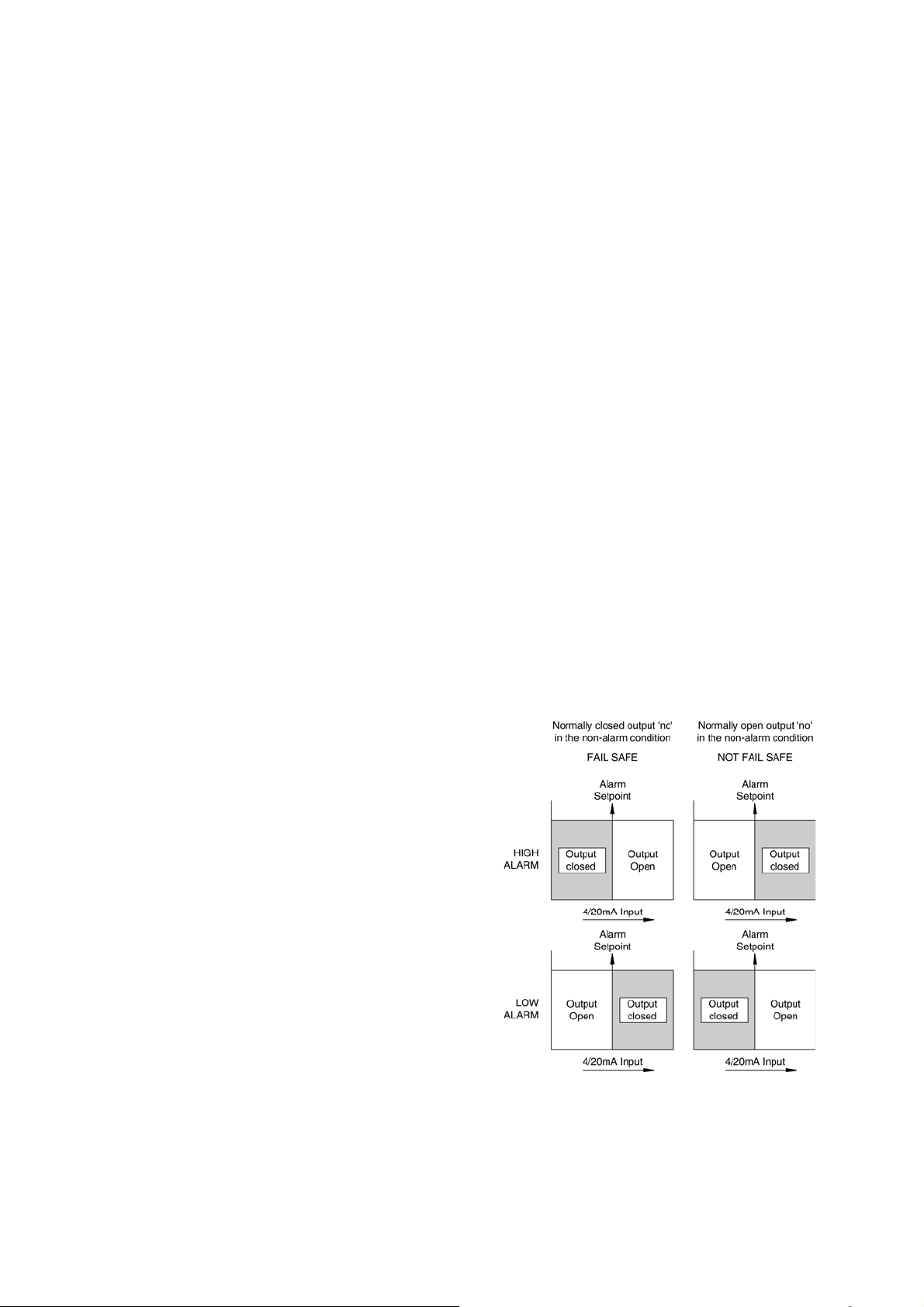
designing an alarm system. Fig 9 illustrates the
conditions available and shows which are fail safe.
When an alarm occurs an alarm annunciator on
the indicator front panel is activated and if required
the numerical display can alternate between the
measured value and the alarm channel
identification ‘ALr1’ or ‘ALr2’.
To gain access to the display label remove the
terminal cover by unscrewing the two 'A' screws
which will reveal two concealed 'D' screws. If the
instrument is fitted with external keypad, also
unscrew the two 'C' screws securing the buttons
and un-plug the five way connector. Finally
unscrew all four 'D' screws and carefully lift off the
front of the instrument. The location of all the
screws is shown in Fig 4.
Add the required legend to the display escutcheon,
or stick a new pre-printed self-adhesive
escutcheon, which is available from BEKA
associates, on top of the existing escutcheon. Do
not remove the original escutcheon.
Both indicators can also be supplied with a blank
or custom laser engraved stainless steel plate
secured by two screws to the front of the
instrument enclosure. This plate can
accommodate:
1 row of 9 alphanumeric characters 10mm high
or 1 row of 11 alphanumeric characters 7mm high
CAUTION
The alarms are activated by the indicator’s
numerical display. Use of the Tare Function
‘tArE’ will change the numerical display, the
alarms will continue to function at the original
displayed value, but this will correspond to a
different input current.
or 2 rows of 18 alphanumeric characters 5mm high
Fig 9 Alarm outputs
Configurable functions for each alarm include
adjustable setpoint, hysteresis, alarm delay and
alarm accept.
Page 19
9.3.1 Solid state output
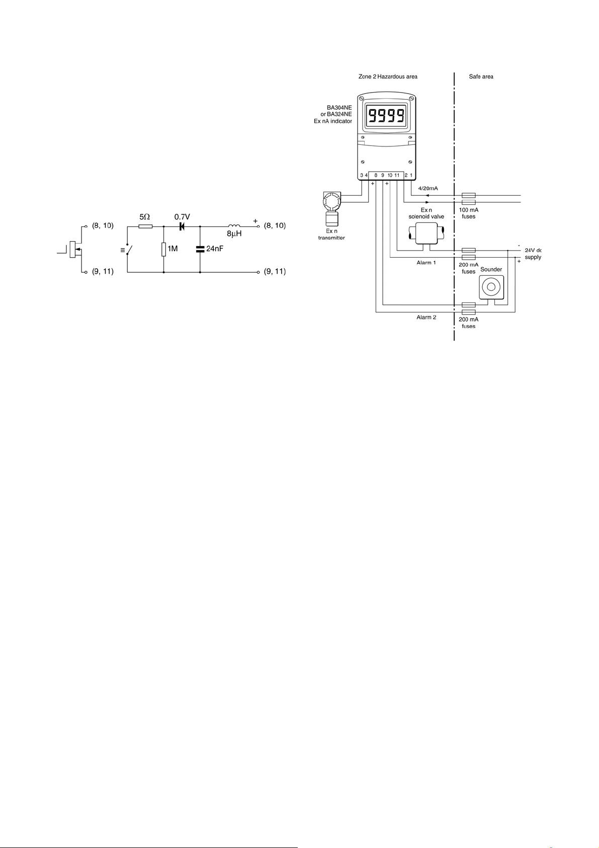
Each alarm output is a galvanically isolated single
pole solid state switch as shown in Fig 10. The
output is polarised and current will only flow in one
direction, terminals 8 and 10 should therefore be
connected to the positive side of the circuit being
switched.
Ron = less than 5Ω + 0.7V
Roff = greater than 1MΩ
Fig 10 Equivalent circuit of each alarm output
19
9.3.2 Type nA certification
Each alarm output is a separate galvanically
isolated Ex nA circuit with the following input
parameters:
Ui = 30V dc
Ii = 200mA
This allows each alarm output to switch any dc
circuit providing that in normal operation the
maximum supply voltage is not greater than 30V
and the switched current is not greater than
200mA.
Fig 11 shows a typical application in which a
BA304NE or BA324NE indicator is displaying the
output from a 2-wire transmitter in Zone 2.
Alarm 1 is switching a solenoid valve in Zone 2
and alarm 2 is switching a sounder located in the
safe area.
The BA304NE and BA324NE indicators have
Ex nA protection but when mounted in Zone 2 the
alarm outputs may be used to switch Ex nC
Protected Sparking and Ex nR Restricted
Breathing apparatus in addition to Ex nA
apparatus.
Fig 11 Typical alarm application
(Shown without recommended screened cables)
To strictly comply with the requirements of
EN 60079:14 Electrical Installation in Hazardous
Areas, each of the wires entering the hazardous
area should be individually fused and contain a
means of isolation. However, in practice
instrumentation energised by a current limited
power supply that can be switched off is often
considered adequate.
Page 20
20
Page 21

21
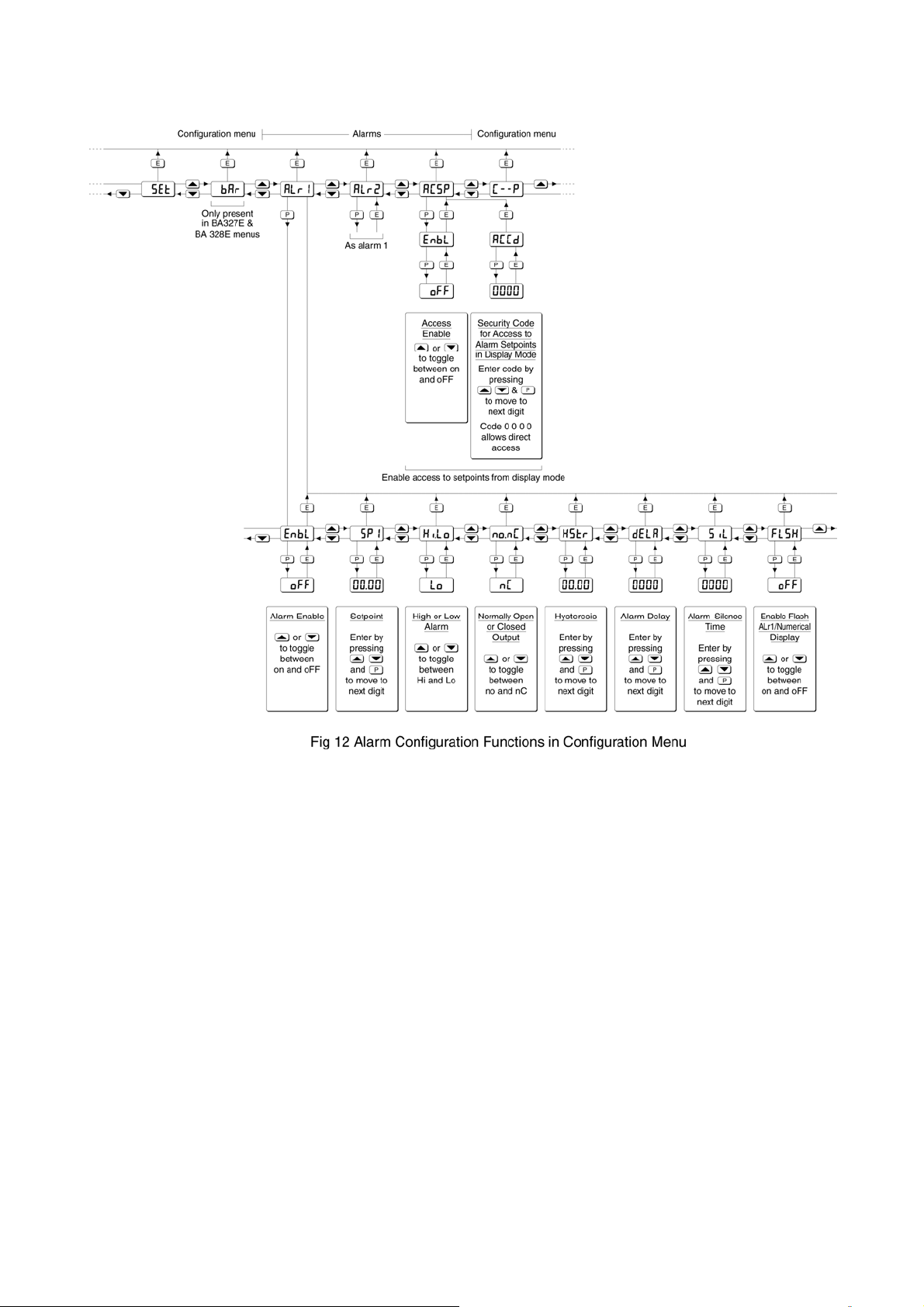
9.3.3 Configuration and adjustment
When optional alarms are fitted to a loop powered
indicator the configuration menu is extended as
shown in Fig 12. The additional functions appear
between the ‘SEt’ and the ‘C- - P’ functions for the
BA304NE and between ‘bAr’ and ‘C- -P’ for the
BA324NE indicator. For simplicity, Fig 12 only
shows the additional functions for alarm 1, but
alarm 2 has identical functions.
The following table summaries each of the alarm
configuration functions and includes a cross
reference to more detailed information.
Summary of alarm configuration functions
Display Description of function
'EnbL’ Alarm enable
Enables or disables the alarm without
changing the alarm parameters.
See section 9.3.4
'SP1' Alarm setpoint 1
Adjusts the alarm setpoint. The alarm
is activated when the indicator display
equals the setpoint.
See section 9.3.5
'Hi.Lo' Alarm function
Defines the alarm function as High or
Low.
See section 9.3.6
'no.nC' Normally open or normally closed
output
Sets the alarm output open or closed in
the non-alarm condition.
See section 9.3.7
'HStr' Hysteresis
Adjusts the alarm hysteresis.
See section 9.3.8
'dELA' Alarm delay time
Introduces adjustable delay between
the display equalling the setpoint and
the alarm output being activated.
See section 9.3.9
'SiL' Alarm silence time
Defines the time that the alarm output
remains in the non-alarm condition
following acceptance of an alarm.
See section 9.3.10
‘FLSH’ Flash display when alarm occurs
When enabled, alternates the
numerical display between process
value and alarm reference, ‘ALr1’ or
‘ALr2’, when an alarm output is
activated.
See section 9.3.11
'ACSP' Access setpoint
Sub-menu which enables direct access
to the alarm setpoints from the indicator
display mode, and defines a separate
security code.
See section 9.3.12
Page 22

22
9.3.4 Alarm enable: ‘EnbL’
This function allows each alarm to be enabled or
disabled without altering any of the alarm
parameters. To enable or disable the alarm select
'EnbL' from the alarm menu and press P which will
reveal the current setting ‘on’ or ‘oFF’. The
function can be changed by pressing the ▲ or ▼
button followed by the E button to return to the
alarm menu.
9.3.5 Setpoint adjustment: ‘SP1’ and ‘SP2’
The setpoint of each alarm may be positioned
anywhere in the numerical display of the indicator
providing that this corresponds to an input current
between 3.8 and 20.2mA. e.g. If the indicator has
been calibrated to display 0 with 4mA input and
10000 with 20mA input, the two alarm setpoints
may be positioned anywhere between -125 and
10125.
To adjust the setpoint select 'SP1' or 'SP2' from the
alarm configuration menu and press P which will
reveal the existing alarm setpoint. The flashing
digit of the setpoint can be adjusted using the ▲
and ▼ push buttons, and the P button to move
control to the next digit. When the required
setpoint has been entered press E to return to the
alarm configuration menu.
The alarm setpoints may also be adjusted when
the indicator is in the display mode, see section
9.3.12.
9.3.6 Alarm function: ‘Hi.Lo’
Each alarm can be independently conditioned as a
high alarm or as a low alarm. To check or change
the alarm function select 'Hi.Lo' from the alarm
menu and press P to reveal the current setting.
The function can be changed by pressing the ▲ or
▼ button followed by the E button to return to the
alarm menu.
To check or change the alarm output status, select
'no.nC' from the alarm configuration menu and
press P to reveal the setting. The function may be
changed by pressing the ▲ or ▼ button followed
by the E button to return to the alarm configuration
menu.
9.3.8 Hysteresis: HStr
Hysteresis is shown in the units that the indicator
has been calibrated to display.
To adjust the hysteresis select 'HStr' from the
alarm menu and press P which will reveal the
existing figure. The flashing digit can be adjusted
using the ▲ and ▼ push buttons, and the P
button will move control to the next digit. When the
required hystersis has been entered press E
to
return to the alarm configuration menu.
e.g. An indicator calibrated to display 0 to 10000,
with a high alarm set at 9000 and hysteresis of 200
will perform as follows:
The high alarm will be activated when
increasing indicator display equals 9000, but
will not reset until the indicator display falls
below 8800.
9.3.9 Alarm delay: dELA
This function delays activation of the alarm output
for an adjustable time following the alarm condition
occurring. The delay can be set in 1 second
increments between 0 and 3600 seconds. If a
delay is not required zero should be entered. To
adjust the delay select 'dELA' from the alarm
configuration menu and press P which will reveal
the existing delay. The flashing digit of the delay
can be adjusted using the ▲ and ▼ push buttons,
and the P button to move control to the other
digits. When the required delay has been entered
press E to return to the alarm menu.
9.3.7 Alarm output status: ‘no.nC’
Configures the solid state alarm output to be open
‘no’ or to be closed ‘nC’ in the non-alarm condition.
When deciding which is required, care should be
taken to ensure that the alarm output is fail safe as
illustrated in Fig 9.
‘no’ Alarm output open in non-alarm condition
‘nC’ Alarm output closed in non-alarm condition
CAUTION
When the 4/20mA supply is removed
from the loop powered indicator, both
alarm outputs will open irrespective of
conditioning. Therefore for fail safe
operation both alarm outputs should be
conditioned to be open in the alarm
condition ‘nC’.
e.g. An indicator with a high alarm set at 9000 and
an alarm delay of 30 seconds will perform as
follows:
The alarm annunciator will start to flash when an
increasing indicator display equals 9000, but the
alarm output will not be activated until the alarm
condition has existed continuously for 30 seconds.
When the alarm output is activated, the alarm
annunciator will stop flashing and become
permanently activated.
If the ‘FLSH’ function, which flashes the indicator
display when an alarm occurs, has been enabled,
it will not start to function until the alarm output is
activated.
See section 9.3.11
Page 23

23
9.3.10 Alarm silence time: SiL
This function is primarily intended for use in small
installations where the alarm output directly
operates an alarm annunciator such as a sounder
or beacon. When the alarm silence time, which is
adjustable between 0 and 3600 seconds in 1
second increments, is set to any figure other than
zero, the P push button becomes an alarm accept
button. After an alarm has occurred, operating the
P button will cause the alarm output to revert to the
non-alarm condition for the programmed alarm
silence time. If the alarm condition still exists at
the end of the silence time, the alarm output will be
reactivated. During the silence time the indicator
alarm annunciator will flash until the silence time
expires or the alarm is cleared.
If the ‘FLSH’ function, which flashes the indicator
display when an alarm occurs has been enabled,
it will only function when the alarm output is
activated, not during the silence time. See section
9.3.11
To adjust the alarm silence time select 'SiL' from
the alarm configuration menu and press P which
will reveal the existing silence time. The flashing
digit of the silence time can be adjusted using the
▲ and ▼ push buttons, and the P button to move
control to the other digits. When the required
silence time has been entered press E to return to
the alarm menu.
indicator is in the display mode is provided by a
separate security code.
This direct setpoint access menu is enabled and
the separate security code entered from the
'ACSP' function in the alarm configuration menu as
shown in Fig 12. To change the menu parameters
select 'ACSP' from the configuration menu and
press P which will display the enable prompt
'EnbL'. Press P again to reveal if the direct access
menu is 'on' or 'oFF'. The ▲ or ▼ button will
toggle the display between the two conditions.
If 'oFF' is selected, the operator will not have
access to the setpoints from the display mode.
Return to the 'ACSP' prompt in the main menu by
pressing E twice.
If 'on' is selected, the operator will have direct
access to the alarm setpoints from the display
mode via a separate optional security code. To
define this four digit security code press P to return
to the 'Enbl' prompt followed by the ▲
or ▼ button
to select the access code prompt 'ACCd'.
Pressing P will reveal the current security code.
Each digit of the code may be changed by
operating the ▲ and ▼ push buttons, and the P
button to move control to the next digit. When the
required code has been entered, press E twice to
return to the 'ACSP' prompt in the configuration
menu.
9.3.11 Flash display when alarm occurs ‘FLSH’
In addition to the two alarm annunciators on the
top left hand corner of the indicator display which
show the status of both alarms, this function
provides an even more conspicuous indication that
an alarm condition has occurred.
When enabled, the function alternates the indicator
display between the numerical value and the alarm
reference, ‘ALr1’ or ‘ALr2’, when the alarm output
is activated. If both alarm outputs are activated,
the alarm references are displayed in sequence.
To enable or disable the function select 'FLSH'
from the alarm menu and press P which will reveal
the current setting ‘on’ or ‘oFF’. The function can
changed by pressing the ▲ or ▼ button followed
by the E button to return to the alarm menu.
9.3.12 Access setpoint in display mode: ACSP
This function enables a separate menu providing
access to the alarm setpoints from the display
mode by simultaneously operating the P and ▲
push buttons. An operator can therefore adjust the
alarm setpoints without having access to the
indicator configuration menu. Protection against
accidental adjustment of the setpoints when the
Default code 0000 will disable the security code
allowing direct access to the setpoints in the
display mode by pressing the P and ▲ buttons
simultaneously. Unless otherwise requested new
instruments with alarms are supplied with this
function disabled and the security code set to
0000.
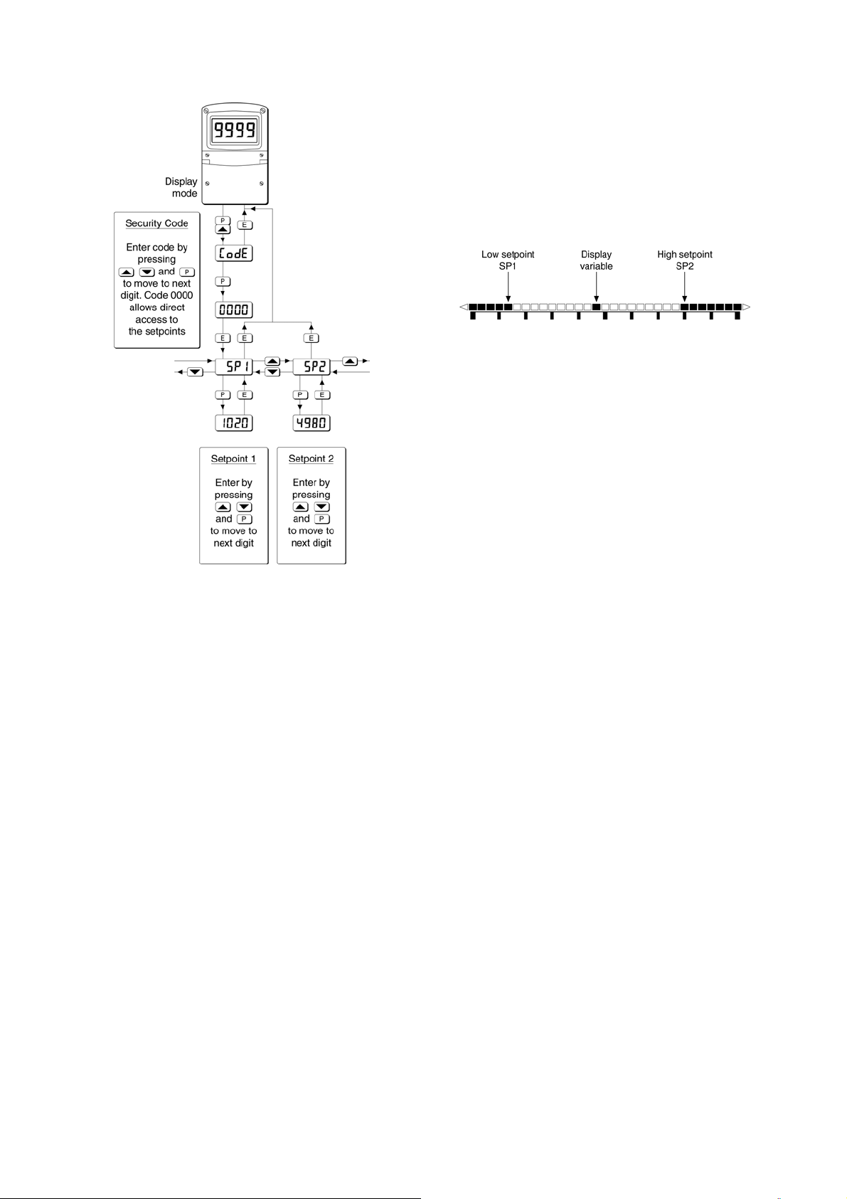
9.3.13 Adjusting alarm setpoints from the
display mode
Access to the alarm setpoints from the indicator
display mode is obtained by operating the P and ▲
push buttons simultaneously as shown in Fig 13. If
the setpoints are not protected by a security code
the alarm setpoint prompt 'SP1' will be displayed.
If the setpoints are protected by a security code,
'Code' will be displayed first. Pressing P again will
enable the alarm security code to be entered digit
by digit using the ▲ and ▼ buttons to change the
flashing digit, and the P push button to move
control to the next digit. If the correct code is
entered pressing E will cause alarm setpoint
prompt 'SP1' to be displayed. Pressing the ▲ or
▼ button will toggle the display between the two
alarm setpoint prompts 'SP1' and 'SP2'.
If an incorrect security code is entered, or a button
is not pressed within twenty seconds, the indicator
will automatically return to the display mode.
Page 24
24
9.3.14 Displaying setpoints on BA324NE
bargraph
One of the selectable bargraph formats ‘AlrSP’
allows a low or a high setpoint plus the displayed
value to be represented, or a low and a high
setpoint plus the displayed value to be represented
by the bargraph as shown in Fig 14.
Fig 14 Displayed value and setpoints on bargraph
The bargraph area below the low alarm setpoint
and the area above the high alarm setpoint are
activated. The displayed variable is represented
by an activated bar which moves between these
low and high alarm setpoints.
Fig 13 Setpoint adjustment from the display mode
To adjust an alarm setpoint select 'SP1' or 'SP2'
and press P which will reveal the current setting.
Each digit of the setpoint may be adjusted using
the ▲ and ▼ push buttons, and the P button to
move control to the next digit. When the required
setpoint has been entered, pressing E will return
the display to the 'SP1' or 'SP2' prompt from which
the other setpoint may be selected, or the indicator
may be returned to the display mode by pressing E
again.
Note: With the indicator in the display mode, direct
access to the alarm setpoints is only available
when the ACSP menu is enabled - see section
9.3.12
When the activated bar representing the displayed
variable is adjacent to the area representing the
low or high ararm setpoints, the bar flashes.
When a displayed variable equals the low or high
alarm the complete bargraph representing the
activated alarm flashes irrespective of whether the
alarm output has been delayed or cleared.
For this function to operate SP1 must be
conditioned as a low alarm and SP2 as a high
alarm; SP1 must always be less than SP2.
Incorrect configuration is shown by a flashing
bargraph scale with no activated bars.
Page 25
25
9.4 Display backlight
The BA304NE and BA324NE loop powered
indicators can be supplied with a factory fitted
backlight that may be loop or separately powered.
When loop powered the backlight produces green
background illumination enabling the display to be
read at night or in poor lighting conditions. No
additional power supply or field wiring are required,
but the indicator voltage drop is increased. When
separately powered the backlight is brighter, but
additional field wiring is required.
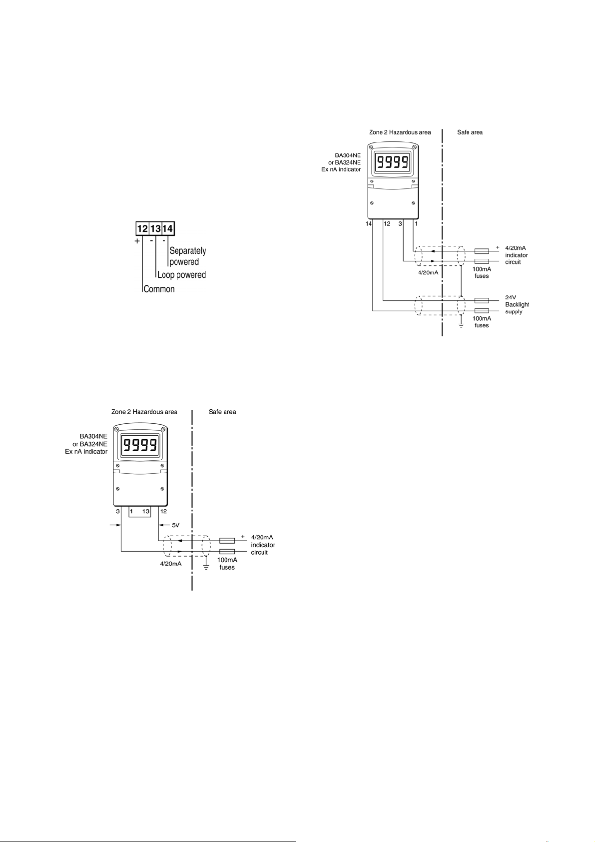
Fig 15 Terminals for optional backlight
9.4.1 Loop powering the backlight
The backlight is loop powered by connecting it in
series with the indicator’s 4/20mA input as shown
in Fig 16, which increases the maximum indicator
voltage drop from 1.2 to 5V.
9.4.2 Separately powering the backlight
The optional backlight may also be powered from a
separate safe area power supply as shown in
Fig 17.
Fig 17 Separately powered backlight
The separately powered backlight is a current sink
which will draw a constant 34.7mA when the
supply voltage is equal to or greater than 11V. At
lower supply voltages the backlight will continue to
function but with reduced brilliance.
Fig 16 Loop powered backlight
To strictly comply with the requirements of
EN 60079:14 Electrical Installation in Hazardous
Areas, each of the wires entering the hazardous
area should be individually fused and contain a
means of isolation. However, in practice
instrumentation energised by a current limited
power supply that can be switched off is often
considered adequate.
The ATEX certificate therefore only specifies the
maximum safety input voltage Ui for terminals 12
and 14.
Ui = 30V
To strictly comply with the requirements of
EN 60079:14 Electrical Installation in Hazardous
Areas, each of the wires entering the hazardous
area should be individually fused and contain a
means of isolation. However, in practice
instrumentation energised by a current limited
power supply that can be switched off is often
considered adequate.
Page 26

9.5 Pipe mounting kits
Two pipe mounting kits are available for securing
the BA304NE and BA324NE to a horizontal or
vertical pipe.
BA392D Stainless steel bracket secured by two
worm drive hose clips. Will clamp to
any vertical or horizontal pipe with an
outside diameter between 60 and
80mm.
BA393 Heavy duty stainless steel bracket
secured by a single 'V' bolt. Will clamp
to any vertical or horizontal pipe with an
outside diameter between 40 and
80mm.
26
Page 27

27
APPENDIX 1
A1.0 ATEX dust certification
In addition to ATEX certification permitting
installation in Zone 2 gas atmospheres which is
described in the main section of this instruction
manual, the BA304NE and the BA324NE also
have ATEX Ex tc certification, allowing installion in
Zone 22 combustible dust atmospheres.
A1.1 Zones and Maximum Surface
Temperature
The indicators have been certified as Group II
Category 3D Ex tc IIIC T80ºC Dc IP66 apparatus
with a Ta of –40ºC to +70C. This is dust ignition
protection by enclosure complying with
EN 60079-31.
When installed as specified in this instruction
manual and complying with the requirements of
EN 61241-14 the indicators may be installed in:
Zone 22 explosive atmosphere in the form of
a cloud of combustible dust in air is
not likely to occur in normal
operation, but if it does occur, will
only persist for a short period.
A1.2 Installation
All the circuits shown in the main section of this
manual for indicator installations in Zone 2
flammable gas atmosheres, may also be used for
Zone 22 combustible dust applications. The
indicator should be located where the minimum
amount of dust will accumulate on the enclosure
and the installation should be as specified in this
instruction manuals and comply with the
requirements of EN 60079-14 Electrical
installations design, selection and erection
EN 60079-14, requires that each of the wires
entering the hazardous area should be individually
fused and contain a means of isolation. However,
in practice instrumentation energised by a current
limited power supply that can be switched off is
often considered adequate.
A1.3 Maintenance
Ex tc protection does not permit live maintenance,
but when fitted with an optional intrinsically safe
external keypad the BA304NE and BA324NE
indicators may be calibrated in Zone 22 providing
the terminal cover is not removed
.
Be used with dusts having a Minimum Ignition
Temperature of:
Dust cloud 120°C
Dust layer on indicator 155
up to 5mm thick.
*
°
C
Dust layer on indicator Refer to
over 5mm thick. * EN 60079-14
At an ambient temperature between -40 and +70°C
* Unlikely occurance in Zone 22
ENSURE PLANT SAFETY BEFORE
STARTING MAINTENANCE
The indicator terminal and control covers
should only be removed and live maintenance
performed when there is little risk of a
combustible dust being present. During
maintenance ensure that dust or water do not
enter the enclosure. Before replacing the
control and terminal covers ensure that the
sealing gaskets are undamaged and free from
dirt and foreign bodies.
Inspection of the indicator’s mechanical condition
and removal of accumulated dust from the outside
of the enclosure should be regularly performed.
The interval between inspections depends upon
environmental conditions. Removal of flammable
dust should be performed with care to avoid
creating a dust cloud.
Page 28

APPENDIX 2
IECEx certification
A2.0 The IECEx Certification Scheme
IECEx is a global certification scheme for
explosion protected products which aims to
harmonise international certification standards.
For additional information about the IECEx
certification scheme and to view the BEKA
associate certificates, please visit www.iecex.com
A2.1 IECEx Certificate of Conformity
The BA304NE and the BA324NE loop powered
indicators and the optional accessories have been
issued with an IECEx Certificate of Conformity
number IECEx ITS 11.0016 that specifies the
following certification codes:
Ex nA ic IIC T5 Gc
Ex tc IIIC T80ºC Dc IP66
Ta = -40ºC to 70ºC
28
The specified gas and dust safety parameters are
identical to the ATEX safety parameters described
in the main section and Appendix 1 of this manual.
The IECEx certificate may be downloaded from
www.beka.co.uk, www.iecex.com or requested
from the BEKA sales office.
A2.2 Installation
The IECEx and ATEX certificates specify identical
safety parameters and installation requirements for
both approvals as defined by IEC 60079-14. The
ATEX installation requirements specified in the
main section and Appendix 1 of this manual should
therefore be used for installations which are made
using the IEC Code of Practice IEC 60079-14.
However the local code of practice should always
be consulted.
 Loading...