

Page 1
Issue: 1
7
th
February 2017
BA314G and BA314E
Intrinsically safe
Tachometers
Issue 1
Page 2

1. Description
2. Operation
2.1 Initialisation
2.2 Controls
2.3 Displays
3. Intrinsic Safety Certification
3.1 ATEX gas certification
3.2 Zones, gas groups & T rating
3.3 Power supply
3.4 Pulse input terminals
3.4.1 sensors that do not require energising.
3.4.2 sensors that require energising
3.5 Remote reset terminals
3.6 Certification label information
4. System Design for Hazardous Areas
4.1 Use with Zener barriers
4.1.1 Power supply
4.1.2 Pulse input
4.1.3 Switch contact input
4.1.4 Open Collector input
4.1.5 2-wire proximity detector input
4.1.6 Magnetic pick-off input
4.1.7 Voltage pulse input
4.1.8 Remote reset
4.2 Use with galvanic isolators
4.2.1 Power supply
4.2.2 Pulse input
4.2.3 Switch contact input
4.2.4 Open collector
4.2.5 2-wire proximity detector input
4.2.6 Magnetic pick-off input
4.2.7 Voltage pulse input
4.2.8 Remote reset
5. Installation
5.1 Location
5.2 Installation procedure
5.3 EMC
5.4 Units of measurement and tag marking on
scale card.
6. Configuration and Calibration
6.1 Calibration structure
6.2 Accessing configuration functions
6.3 Summary of configuration functions
6.4 Input: inPut
6.5 Input type: inP
. tYPE
6.6 Debounce: dEbouncE
6.7 Display update interval: uPdAtE
6.8 Run-time display: di5P-2
6.9 Position of the decimal points: dP
6.10 Speed scale factor: 5CALE
. 5
6.11 Timebase: t-bA5E
6.12 Display filter: FiLtEr
6.13 Clip-off: CLP oFF
6.14 Local reset: LoC clr
6.15 Local run-time reset: clr tot
6.16 Local grand total run-time reset: clr gtot
6.17 Grand total run-time reset from within the
configuration menu: Clr
. Gtot
6.18 Security code: CodE
6.19 Reset configuration to factory defaults:
r5Et def
6.20 Pulse output
6.20.1 Intrinsic safety
6.20.2 System designing
6.20.3 Configuration
6.20.4 Access Pulse output sub-menu
6.20.5 Enable pulse output
6.20.6 Source of output pulse
6.20.7 Divide output pulse frequency
6.20.8 Define output pulse width
6.20.9 Pulse storage
7. Configuration example
7.1 Configuration procedure
8. Maintenance
8.1 Fault finding during commissioning
8.2 Fault finding after commissioning
8.3 Servicing
8.4 Routine maintenance
8.5 Guarantee
8.6 Customer comments
2222222222222222222
CONTENTS
The BA314G and BA314E are CE marked to show compliance with the European Explosive Atmospheres
Directive 2014/34/EU and the European EMC Directive 2014/30/EU
Page 3

9. Accessories
9.1 Units of measurement and instrument
identification.
9.2 Display backlight
9.3 Alarms
9.3.1 Solid state output
9.3.2 Intrinsic safety
9.3.3 Configuration & adjustment
9.3.4 Alarm enable: EnbL
9.3.5 Type of alarm: tYPE
9.3.6 Setpoint adjustment: 5P1x & 5P2x
9.3.7 Alarm function: Hi
. Lo
9.3.8 Alarm output status: no
. nC
9.3.9 Hysteresis: H5tr
9.3.10 Alarm delay: dELA
9.3.11 Alarm silence time: 5IL
9.3.12 Flash display when alarm occurs:
FL5H
9.3.13 Access Setpoint: AC5P
9.3.14 Adjusting alarm setpoints
from the display mode.
9.4 4/20mA output
9.4.1 Intrinsic safety
9.4.2 System design
9.4.3 Configuration & calibration
9.4.4 Access 4/20mA output sub-menu:
4-20 oP
9.4.5 Enable 4/20mA output: EnbL
9.4.6 Display which corresponds to 4mA
output: 4
. 000
9.4.7 Display which corresponds to 20mA
output: 20 . 000
Appendix 1 Dust certification
Appendix 2 IECEx certification
Appendix 3 ETL & cETL certification for
installation in USA and Canada.
Appendix 4 BA314E Tachometer
3
CONTENTS CONTINUED
Page 4

4
Page 5
1. DESCRIPTION
These intrinsically safe, Tachometers are primarily
intended for measuring rotational speed within
hazardous areas. To assist with routine maintenance,
they also include a run-time clock that records the
number of hours that the monitored machinery has
been operating.
The BA314G and the BA314E are functionally
identical and have similar certifications, but differ in
mechanical construction and options.
The differences are summarised in the following table.
BA314G BA314E
Separate
terminal
compartment.
No Yes
Pulse output Yes Yes
Backlight Option Yes
4/20mA output. Option Yes
Dual alarms Option Yes
Certification
IECEx Gas & dust Gas
ATEX Gas & dust Gas
ETL & cETL Gas & dust Gas & dust
The main sections of this instruction manual describe
the BA314G, but also apply to the BA314E. Details of
the BA314E mounting and terminals are contained in
Appendix 4.
The BA314G and BA314E have been ATEX certified
intrinsically safe by Notified Body Intertek Testing and
Certification Ltd and comply with the European ATEX
Directive 2014/34/EU. The BA314G has gas and dust
certification, but the BA314E only has ATEX gas
certification.
The main sections of this manual describe ATEX gas
certification.
For international applications the BA314G and
BA314E also have IECEx certification which is
described in Appendix 2. The BA314E does not
have IECEx dust certification.
For applications in the USA and Canada the BA314G
and BA314E have ETL & cETL certification which is
described in Appendix 3.
2. OPERATION
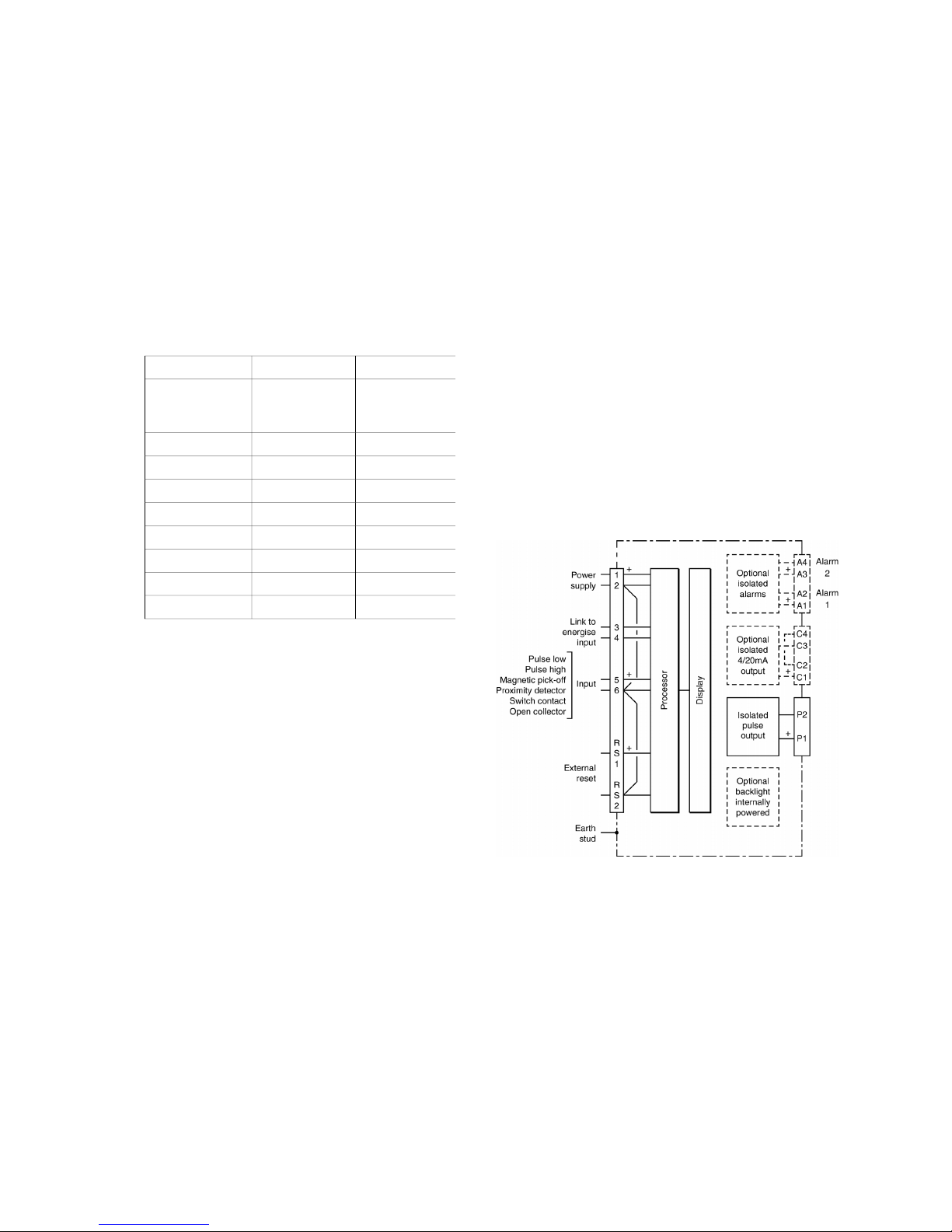
Fig 1 shows a simplified block diagram of the
BA314G Tachometer. The instrument can accept
pulses from most types of sensor and display speed
per second, minute or per hour, plus run-time in
hours on a separate display.
The BA314G has a single pair of input terminals for
connection to all types of sensor. When connected to
a sensor requiring energising, such as a switch
contact, open collector or a two wire proximity
detector, an external link between terminals 3 and 4
connects power to the sensor input terminals. An
isolated pulse output can be configured to
synchronously retransmit the pulse input, or a
frequency divided frequency output with a defined
pulse width.
Factory fitted accessories include an internally
powered display backlight, dual alarms and an
isolated 4/20mA output which may be configured to
retransmit any part of the speed display.
Fig 1 BA314G block diagram
5
Page 6

2.1 Initialisation
Each time power is applied to a Tachometer
initialisation is performed. After a short delay the
following display sequence occurs:
All segments of the display are activated
Tachometer starts functioning, using the
configuration information stored in the
instrument’s permanent memory. Unless the
run-time display has been reset to zero, new
elapsed time will be added to the existing runtime total.
2.2 Controls
The BA314G is controlled and configured via four
front panel push buttons. In the display mode i.e.
when the instrument is displaying speed the push
button functions are:
Push Button Functions
& + * Resets run-time display to zero.
This is a configurable function.
See 6.15
)
+ * Run-time grand total.
If buttons are pressed for ten seconds or
longer grand total run-time is reset to
zero. This is a configurable function.
See 6.16
( + & Shows in succession, firmware version
number, instrument function tacho and
any output accessories that are fitted:
- A Dual alarm outputs
- P Pulse output
(Fitted to all BA314G)
- C 4/20mA output
( + ) Access to configuration menu
Note: When optional alarms are fitted, the
Tachometer may be configured to provide direct
access to the alarm setpoints from the display mode
when the ( + * buttons are operated.
See 9.4.13 and 9.4.14
2.3 Displays
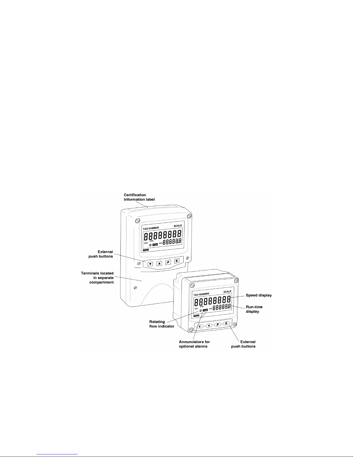
The BA314G has two digital displays and associated
annunciators, plus a pulse input indicator as shown
on page 1.
Speed On upper eight digit display
display
Run-time On lower six digit display.
display Shows time in hours, with a
resolution of 0.1 hours, that
monitored machinery has been
operating. May be turned off.
See 6.8
Pulse input This disc in the lower left hand
indicator corner of the display 'rotates'
for two seconds each time an
input pulse is received.
Appears to rotate continuously
when input frequency exceeds
0.5Hz.
Hold Activated when input frequency
annunciator is below the clip-off threshold at
which the run-time timer stops
functioning.
Reset Activated while run-time display
annunciator is being reset to zero.
Grand total Activated while run-time grand
annunciator total which is shown in hours is
being displayed.
6
Page 7

3. INTRINSIC SAFETY CERTIFICATION
The BA314G has ATEX and IECEx gas and dust
certification. This section of the instruction manual
describes ATEX gas certification. ATEX dust and
IECEx approvals are described in Appendixes
1 and 2.
3.1 ATEX gas certification
Notified Body Intertek Testing and Certification Ltd
have issued the BA314G with an EU-Type
Examination Certificate number ITS16ATEX28408X.
This confirms compliance with harmonised European
standards and it has been used to confirm compliance
with the European ATEX Directive for Group II,
Category 1G equipment, Ex ia IIC T5 Ga equipment.
The Tachometer carries the community mark and,
subject to local codes of practice, may be installed in
any of the European Economic Area (EEA) member
countries. ATEX certificates are also acceptable for
installations in Switzerland.
This section of the instruction manual describes ATEX
installations in explosive gas atmospheres conforming
with EN 60079-14 Electrical installations design,
selection and erection. When designing systems for
installation outside the UK the local Code of Practice
should be consulted.
3.2 Zones, gas groups and T rating
The BA314G Tachometer has been certified
Ex ia IIC T5 Ga. When connected to a suitable
system it may be installed in:
Zone 0 explosive gas air mixture
continuously present.
Zone 1 explosive gas air mixture likely
to occur in normal operation.
Zone 2 explosive gas air mixture not
likely to occur, and if it does
will only exist for a short time.
Be used with gases in groups:
Group A propane
Group B ethylene
Group C hydrogen
In gases that may be used with equipment having a
temperature classification of:
T1 450°C
T2 300°C
T3 200°C
T4 135°C
T5 100°C
At ambient temperatures between -40 and +70°C.
CAUTION installation in Zone 0
When installed in a Zone 0 potentially explosive
atmosphere requiring EPL Ga apparatus, the
instrument shall be installed such that even in
the event of rare incidents, an ignition source
due to impact or friction between the aluminium
label and iron/steel is excluded.
No special conditions apply when the BA314G
Tachometer is installed in Zone 1 or in Zone 2. This
allows the BA314G to be installed in all gas Zones
and to be used with most common industrial gases
except carbon disulphide and ethyl nitrite which have
an ignition temperature of 95°C.
3.3 Power supply
When installed in a hazardous area the BA314G
should be powered from a certified Zener barrier,
galvanic isolator or associated apparatus with an
intrinsically safe voltage output.
The safety parameters of terminals 1 and 2 are:
Ui = 28V dc
Ii = 200mA dc
Pi = 0.84W
Uo = 0
Io = 0
Any certified Zener barrier, galvanic isolator or
associated apparatus with output safety parameters
equal to or less than these input limits may be used.
The maximum equivalent capacitance and
inductance between terminals 1 and 2 is:
Ci = 2nF
Li = 4µH
To determine the maximum permissible cable
parameters the above figures, which are small and
may be ignored in some applications, should be
subtracted from the maximum permitted cable
parameters specified for the Zener barrier, galvanic
isolator or associated apparatus powering the
BA314G Tachometer.
7
Page 8

3.4 Pulse input terminals
The BA314G Tachometer has a single pair of pulse
input terminals 5 and 6 that may be configured for use
with different types of sensor.
For sensors that require energising to determine their
state, such as switch contacts or a 2-wire proximity
detector, an external link between terminals 3 & 4 of
the BA314G connects an internal 7V, 6mA supply to
the input. Energising is not required when the
Tachometer's input is connected to a voltage pulse
source.
Fitting an external link between terminals 3 & 4
changes the output safety parameters of the
Tachometer input terminals 5 & 6 as shown in the
following table. This table also shows the types of
sensor requiring energising (link fitting).
Output safety parameters
Type of input Link 3 & 4 Uo Io Po
Switch contact Yes 10.5V 9.2mA 24mW
Proximity detector Yes 10.5V 9.2mA 24mW
Open collector Yes 10.5V 9.2mA 24mW
Magnetic pick-off No 1.1V 0.5mA 0.2mW
Voltage input (low) No 1.1V 0.5mA 0.2mW
Voltage input (high) No 1.1V 0.5mA 0.2mW
3.4.1 Sensor not requiring energising
Sensors employing magnetic pick-offs or voltage
pulse sensors do not require energising, therefore
terminals 3 & 4 should not be linked. When not
energised i.e. without a link, the output parameters of
the pulse input terminals comply with the
requirements for simple apparatus. For intrinsic
safety purposes, sources of energy with output
parameters less than 1.5V; 100mA and 25mW are
considered to be simple apparatus (Clause 5.7 of
EN60079-11), which allows their output parameters
Uo, Io & Po to be ignored when assessing the safety
of an intrinsically safe system, thus simplifying loop
assessment and documentation.
Almost any Sensor with a voltage pulse output may be
directly connected to the BA314G input in a
hazardous area providing that:
a. The Sensor is a certified intrinsically safe device
having output parameters equal to or less than:
Uo 28V dc
Io 200mA dc
Po 0.84W
or complies with requirements for
simple apparatus.
b. The Sensor and associated wiring can withstand
a 500V rms insulation test to earth.
c. The Sensor is located in the same hazardous
area as the BA314G. The BA314G EU-Type
Examination Certificate specifies that the
equivalent capacitance and inductance of the
pulse input is:
Ci = 2nF
Li = 4µH
To determine the maximum permissible cable
parameters these figures should be subtracted from
the maximum permitted output parameters Lo and
Co specified by the certificate for the Sensor
connected to the totaliser's pulse input terminals.
The totalisers pulse input equivalent capacitance
and inductance are small and unlikely to make a
significant difference to the allowable cable
parameters.
3.4.2 Sensors requiring energising
Sensors with switch contacts, proximity detector or
open collector outputs require energising which is
achieved by linking Tachometer terminals 3 and 4
together as described in section 3.4. When
energised, the output parameters of the pulse input
terminals 5 and 6 are:
Uo = 10.5V dc
Io = 9.2mA dc
Po = 24mW
These output parameters do not comply with the
requirements for simple apparatus and should be
considered when assessing the safety of the Sensor
connected to the totaliser pulse input.
Any certified intrinsically safe Sensor may be
connected to a BA314G energised input providing
that:
a. The Sensor is a certified intrinsically safe
device having input parameters equal to or
greater than:
Uo 10.5V dc
Io 9.2mA dc
Po 24mW
or complies with the requirements for
simple apparatus such as switch
contacts.
b. The Sensor and associated wiring can
withstand a 500V rms insulation test to earth.
c. The Sensor is located in the same hazardous
area as the BA314G.
d. Minimum operating voltage of a proximity
detector is less than 7.5V.
e. The maximum capacitance and inductance that
may be safely connected to the energised
pulse input terminals 5 & 6 (terminals 3 & 4
linked) is:
Co = 2.4µF
Lo = 200mH
This is not restrictive as the combined capacitance
and inductance of most sensors and the connecting
cable will be less than this.
8
Page 9
3.5 Remote reset terminals
The BA314G run-time display may be reset to zero by
connecting the external reset terminals RS1 and RS2
together for more than one second. The two reset
terminals have the following input and output safety
parameters:
Uo = 3.8V dc
Io = 1mA
Po = 1mW
Ui = 28V dc
Ii = 200mA dc
Pi = 0.84W
The equivalent capacitance and inductance between
them is:
Ci = 0
Li = 0
The maximum cable capacitance and inductance that
may be safely connected between the reset terminals
RS1 and RS2 is:
Co = 40µF
Lo = 1H
The reset terminals may be directly connected to any
mechanically operated switch located within the same
hazardous area as the BA314G Tachometer. The
switch and associated wiring should be able to
withstand a 500V insulation test to earth.
If the reset switch is required in the safe area a Zener
barrier or intrinsically safe relay is required to transfer
the contact closure into the hazardous area. Almost
any intrinsically safe relay with certification permitting
the contacts to be connected to equipment in the
hazardous area may be used. A diode return Zener
barrier is not suitable for this application.
Alternatively the BA314G may be configured so that
the total display is reset to zero when the & and *
push buttons are operated simultaneously for more
than two seconds. See 6.19
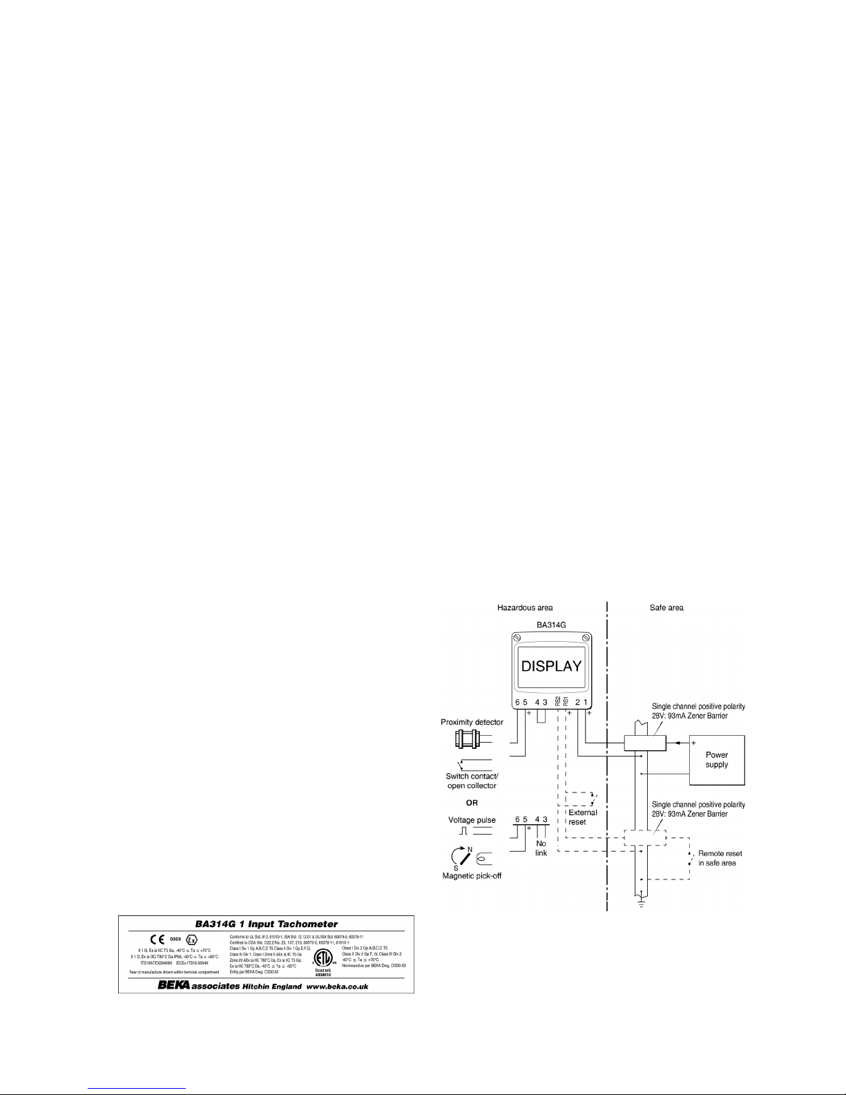
3.6 Certification label information
The Tachometer certification information label is fitted
in a recess on the top outer surface of the instrument
enclosure. It shows the ATEX, IECEx and ETL
certification information plus BEKA associates name,
location, year of manufacture and the instrument
serial number. Other certification information may
also be included.
BA314G Certification information label
4. SYSTEM DESIGN FOR HAZARDOUS AREAS
4.1 Use with Zener barriers
Zener barriers are the least expensive intrinsically
safe interface between a safe and hazardous area.
However they require a high integrity earth
connection that may be expensive to install and they
do not provide isolation. When a high integrity earth
connection is not already available, it may be less
expensive and complicated to use galvanic isolators
for the installation of a single BA314G.
Terminals 2, 6 and RS2 of the BA314G Tachometer
are internally connected together. If any of these
terminals are earthed, as shown in Figs 2 & 3, the
other common terminals should only be connected
to the same earth, i.e. the barrier busbar, or to
circuits that have 500V insulation to earth.
Any Zener barrier may be used with the BA314G
providing it's certification is for use with apparatus in
the required Zone and gas group, and it's output
parameters do not exceed the input parameters of
the Tachometer terminals to which it is connected.
Only one polarity of Zener barrier i.e. positive or
negative, may be used in a Tachometer system.
Fig 2 illustrates the basic circuit that is used for all
BA314G installations protected by Zener barriers.
For simplicity, connections for the pulse output and
optional alarms and 4/20mA output are shown
separately in sections 6.20 and 9 of this manual.
Fig 2 BA314G used with Zener barriers
9
Page 10
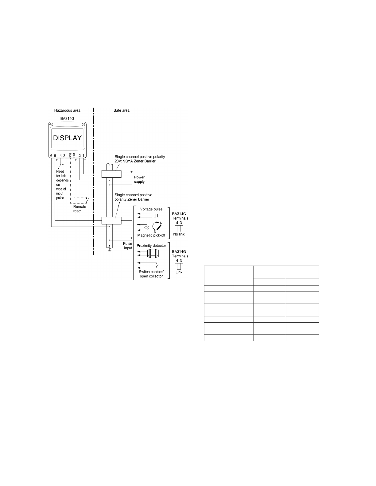
Alternatively the pulse source may be located in the
safe area. Fig 3 shows how an additional Zener
barrier is used to transfer the signal to the Tachometer
in the hazardous area. When more than one Zener
barrier is used in a system all must have the same
polarity, i.e. all positive or all negative barriers.
When designing a system it is important to remember
that terminals 2, 6 and RS2 are interconnected within
the BA314G. See Fig 1.
Fig 3 BA314G used with Zener barriers pulse source
in the safe area.
4.1.1 Power supply
The BA314G Tachometer requires a minimum of 10V
between terminal 1 & 2 and consumes:
10mA without optional backlight
plus 6mA when terminals 3 & 4 are linked
Any certified Zener barrier may be used to power a
BA314G Tachometer providing the output safety
parameters of the barrier are equal to or less than the
input safety parameters of terminals 1 & 2 of the
Tachometer.
Although this allows a wide variety of barriers to be
used, a positive polarity 28V; 93mA; 300 Zener
barrier, which has an end-to-end resistance of about
340, is an industry standard device which is
frequently used. With this barrier the supply voltage
in the safe area must be between 15.5V and the
maximum working voltage of the Zener barrier
which, depending upon manufacturer, will be
approximately 26V.
Note: The optional factory fitted display backlight
increase the instrument's current
consumption to 32mA and therefore
increases the minimum safe area operating
voltage, see section 9.2 for details.
4.1.2 Pulse input
As shown in Figs 2 and 3 the BA314G can display
the rate and total flow from sensors with a wide
variety of pulse outputs located in safe and
hazardous areas.
No Zener barrier is required in series with the input if
the intrinsically safe sensor is located within the
same hazardous area as the Tachometer. The
following table shows the Tachometer's input
switching thresholds when conditioned for use with
sensors having different outputs, For reliable
totalisation the Tachometer pulse input must fall
below the lower threshold and rise above the upper
threshold.
Input transducer
Switching thresholds
Lower Upper
Open collector 2k 10k
Voltage pulse
low
1.0V 3.0V
Voltage pulse
high
3.0V 10.0V
Magnetic pick-off 0 40mV peak
Proximity
detector
1.2mA 2.1mA
Switch 100 1000
Switch contact, proximity detector or open collector
sensors require energising which is achieved by
linking Tachometer terminals 3 and 4.
10
Page 11

4.1.3 Switch contact input
Any mechanically or magnetically activated switch
contact located in the same hazardous area as the
Tachometer may be directly connected to pulse input
terminals 5 and 6, providing the sensor and
associated wiring can withstand a 500V rms insulation
test to earth. Most magnetically activated reed relays
comply with these requirements and the requirements
for simple apparatus. The BA314G contains a
configurable debounce circuit to prevent false
triggering. Three levels of de-bounce protection are
available. See section 6.6.
4.1.4 Open collector input
Most certified intrinsically safe sensors with an open
collector output may be directly connected to a
BA314G input terminals 5 & 6, providing the input
safety parameters of the open collector sensor are
equal to or greater than the output safety parameters
of Tachometer's pulse input. i.e.
Ui 10.5V dc
Ii 8.2mA dc
Pi 24mW
The open collector sensor must be located in the
same hazardous area as the BA314G and the
associated wiring should be able to withstand a 500V
rms insulation test to earth.
The BA314G contains a configurable debounce circuit
to prevent false triggering. Three levels of de-bounce
protection are available. See section 6.6.
4.1.5 2-wire proximity detector input
Most certified intrinsically safe sensors incorporating a
NAMUR 2-wire proximity detector may be directly
connected to a BA314G input, providing the input
safety parameters of the sensor (proximity detector)
are equal to or greater than the output safety
parameters of Tachometer's pulse input. i.e.
Ui 10.5V dc
Ii 8.2mA dc
Pi 24mW
The minimum operating voltage of the sensor
(proximity detector) should be less than 7.5V. The
sensor must be located in the same hazardous area
as the BA314G and the associated wiring should be
able to withstand a 500V rms insulation test to earth.
The Tachometers contain a configurable debounce
circuit to prevent false triggering. Three levels of
debounce protection are available. See section 6.6.
4.1.6 Magnetic pick-off input
Sensors incorporating a magnetic pick-off to sense
movement will have a low level voltage output
unless the sensor incorporates an amplifier. CoiL in
the BA314G input configuration menu is a low level
voltage pulse input intended for use with an
intrinsically safe magnetic pick-off. When a
Tachometer is configured for CoiL and terminals 3 &
4 are not linked, the input terminals 5 & 6 comply
with the requirements for simple apparatus allowing
connection to any certified intrinsically safe magnetic
sensor having output parameters equal to or less
than:
Uo 28V dc
Io 200mA dc
Po 0.84W
The maximum permitted cable parameters will be
the magnetic pick-off's Co and Lo specified on it's
intrinsic safety certificate, less the Tachometers
pulse input parameters Ci and Li which are small
and can often be ignored.
The sensor must be located within the same
hazardous area as the Tachometer and with the
associated wiring be able to withstand a 500V rms
insulation test to earth.
The Tachometer contains a configurable debounce
circuit to prevent false triggering. Three levels of
debounce protection are available. See section 6.6.
4.1.7 Voltage pulse input
Two voltage pulse input ranges are selectable in the
BA314G Tachometer configuration menu, VoLt5 L
and VoLt5 H
. When configured for either of the
voltage pulse ranges and terminals 3 & 4 are not
linked, the input terminals 5 & 6 comply with the
requirements for simple apparatus. This allows the
input to be connected to any certified intrinsically
safe voltage out[put sensor located in the same
hazardous area as the Tachometer having output
parameters equal to or less than:
Uo 28V dc
Io 200mA dc
Po 0.84W
The Tachometer input may therefore be directly
connected to most certified intrinsically safe sensors
with a high level voltage pulse output.
The maximum permitted cable parameters will be
defined by the intrinsic safety certification of the
sensor less the Tachometers input parameters Ci &
Li which are small and can often be ignored.
The Tachometers contain a configurable debounce
circuit to prevent false triggering of the instrument.
Three levels of de-bounce protection are available.
See section 6.7.
11
Page 12
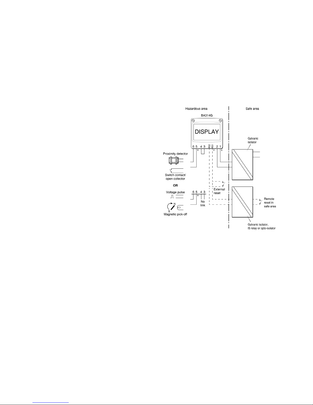
4.1.8 Remote reset
The Tachometer's run-time display may be remotely
reset to zero by connecting terminals RS1 and RS2
together for more than one second. Permanent
interconnection inhibits the run-time clock. Remote
resetting may be accomplished by any mechanically
operated switch located in the same hazardous area
as the Tachometer providing the switch and the
associated wiring can withstand a 500V rms insulation
test to earth. No Zener barrier is required.
A BA314G may also be remotely reset from the safe
area. Any switch may be used but a Zener barrier is
required to transfer the contact closure into the
hazardous area which may be combined with the
supply barrier so that only one package is required. A
diode return barrier is not suitable for this application.
Fig 2 illustrates how a BA314G may be reset from
both the safe and the hazardous area.
Note: The Tachometer may be configured to reset
the total display to zero by operating the &
and * push buttons simultaneously for more
than two seconds in the totalising mode i.e.
when the instrument is displaying flow. See
section 6.15.
4.2 Use with Galvanic Isolators
Galvanic isolators are probably the simplest
intrinsically safe interface to install as they provide
isolation and do not require a high integrity earth
connection.
Any galvanic isolator may be used with the BA314G
providing it's certification is for use with apparatus in
the required Zone and gas group, and it's output
parameters do not exceed the input parameters of
the Tachometer terminals to which it is connected. It
must also have the correct function.
Fig 4 BA314G used with galvanic isolators.
Fig 4 illustrates the basic circuit that is used for all
BA314G Tachometer installations protected by
galvanic isolators. For simplicity, connections for
the pulse output, optional alarms and 4/20mA output
are shown in sections 6.20 and 9 of this manual.
The Tachometer’s pulse source may also be located
in the safe area as shown in Fig 5. An additional
galvanic isolator is used to transfer the signal to the
Tachometer in the hazardous area, although it may
be difficult to find isolators for transferring some
sensor outputs.
12
Page 13
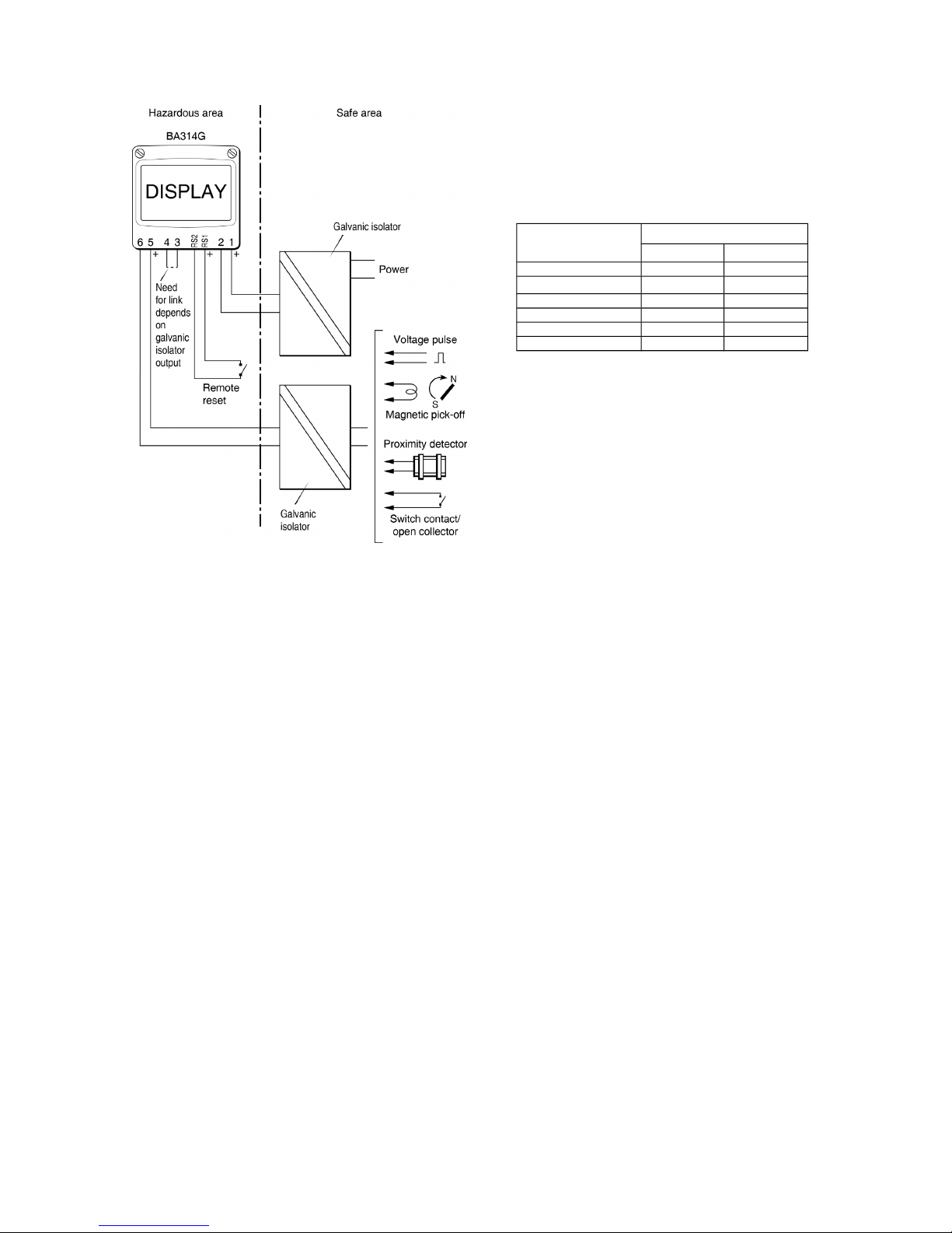
Fig 5 Pulse source in safe area
4.2.1 Power supply
The BA314G Tachometer requires a minimum of 10V
between terminal 1 & 2 and consumes:
10mA without optional backlight
plus 6mA when terminals 3 & 4 are
linked.
The total current increases to 32mA when an optional
backlight is fitted.
Any galvanic isolator certified for the gas group and
Zone in which the BA314G is installed may be used to
power the instrument. The output safety parameters
of the isolator must be equal to or less than the input
safety parameters of terminals 1 & 2 and the voltage
at terminals 1 & 2 must be greater than 10V. These
requirements are not restrictive and allow a wide
range of galvanic isolators, such as solenoid drivers,
to be used.
4.2.2 Pulse input
As shown in Figs 4 and 5 the BA314G input can be
directly connected to hazardous area sensors, or to
safe area sensors via an isolator. Galvanic isolators
are not required in series with the input if the
intrinsically safe sensor is located within the same
hazardous area as the Tachometer.
The BA314G Tachometer may be used with sensors
having a wide variety of pulse outputs. The following
table shows the switching thresholds for each type.
For reliable operation the Tachometers input signal
must fall below the lower threshold and rise above
the upper threshold.
Input transducer Switching thresholds
Lower Upper
Open collector 2k 10k
Voltage pulse low 1.0V 3.0V
Voltage pulse high 3.0V 10.0V
Magnetic pick-off 0mV 40mV peak
Proximity detector 1.2mA 2.1mA
Switch 100 1000
Switch contacts, proximity detectors and open
collector sensors require energising which is
achieved by linking terminals 3 and 4 together as
shown in Figs 4 and 5.
4.2.3 Switch contact input
Any sensor with a mechanical or magnetically
activated switch contact output may be directly
connected to input terminals 5 & 6 providing the
sensor is located in the same hazardous area as the
Tachometer and the sensor and associated wiring
can withstand a 500V rms insulation test to earth.
Most magnetically activated reed relays comply with
these requirements. The BA314G contain a
configurable debounce circuit to prevent contact
bounce being counted. Three levels of de-bounce
protection are independently available. See section
6.6.
4.2.4 Open collector input
Most certified intrinsically safe open collector
sensors may be directly connected to the BA314G
input terminals 5 & 6, providing the input safety
parameters of the open collector sensor are equal to
or greater than the output safety parameters of
Tachometer's pulse input. i.e.
Ui 10.5V dc
Ii 8.2mA dc
Pi 24mW
The open collector sensor must be located in the
same hazardous area as the BA314G and the
associated wiring should be able to withstand a
500V rms insulation test to earth.
The BA314G contains a configurable debounce
circuit to prevent false triggering. Three levels of debounce protection are independently available. See
section 6.6.
13
Page 14

4.2.5 2-wire proximity detector input
Most certified intrinsically safe NAMUR 2-wire
proximity detectors may be directly connected to a
BA314G input, providing the input safety parameters
of the proximity detector are equal to or greater than
the output safety parameters of a BA314G input:
Ui 10.5V dc
Ii 8.2mA dc
Pi 24mW
and the minimum operating voltage of the proximity
detector is less than 7.5V. The proximity detector
must be located in the same hazardous area as the
Tachometer and the associated wiring must be able to
withstand a 500V rms insulation test to earth.
The BA314G contain a configurable debounce circuit
to prevent false triggering of the instrument. Three
levels of de-bounce protection are available.
See section 6.6.
4.2.6 Magnetic pick-off input
CoiL in the BA314G input configuration menu is a low
level voltage pulse input intended for use with an
intrinsically safe magnetic pick-off. When a
Tachometer input is configured for CoiL and terminals
3 & 4 are not linked, input terminals 5 & 6 comply with
the requirements for simple apparatus allowing
connection to any certified intrinsically safe magnetic
sensor having output parameters equal to or less
than:
Uo 28V dc
Io 200mA dc
Po 0.84W
The maximum permitted cable parameters will be be
the sensor's Co and Lo specified on it's intrinsic safety
certificate, less the Tachometers pulse input
parameters Ci and Li which are small and can often
be ignored.
The sensor must be located within the same
hazardous area as the BA314G and with the
associated wiring must be able to withstand a 500V
rms insulation test to earth.
The BA314G Tachometer contains a configurable
debounce circuit to prevent false triggering. Three
levels of debounce protection are available. See
section 6.6.
4.2.7 Voltage pulse input
Two voltage pulse input ranges are independently
selectable in the BA314G Tachometer configuration
menu, VoLt5 L and VoLt5 H. When configured for
either of the voltage pulse ranges, and terminals 3 &
4 are not linked, the input terminals 5 & 6 comply
with the requirements for simple apparatus. This
allows the pulse input to be connected to any
certified intrinsically safe sensor with a voltage
output located within the same hazardous area as
the Tachometer providing it has output parameters
equal to or less than:
Uo 28V dc
Io 200mA dc
Po 0.84W
The BA314G Tachometers may therefore be directly
connected to most certified intrinsically safe sensors
with a high level voltage output.
The maximum permitted cable parameters will be
defined by the sensor's intrinsic safety Co and Lo
less the Tachometer's pulse input parameters Ci and
Li which are small and can often be ignored.
The BA314G contain a configurable debounce circuit
to prevent false triggering of the instrument. Three
levels of de-bounce protection are available.
See section 6.6.
4.2.8 Remote reset
The Tachometer's run-time display may be remotely
reset to zero by connecting terminals RS1 and RS2
together for more than one second. Permanent
interconnection inhibits the run-time clock. Remote
resetting may be accomplished by any mechanically
operated switch located in the same hazardous area
as the Tachometer providing the switch and the
associated wiring can withstand a 500V rms
insulation test to earth. No galvanic isolator is
required.
A BA314G may also be remotely reset from the safe
area. Any switch may be used but a galvanic
isolator is required to transfer the contact closure
into the hazardous area. Fig 4 illustrates how a
BA314G may be reset from both the safe and the
hazardous area.
Note: The BA314G Tachometer may be
configured to reset the total display to zero
by operating the & and * push buttons
simultaneously for more than two seconds
in the totalising mode i.e. when the
instrument is displaying flow. See 6.15
14
Page 15
5. INSTALLATION
5.1 Location
The BA314G Tachometer is housed in robust IP66
glass reinforced polyester (GRP) enclosure
incorporating an armoured glass window and stainless
steel fittings making it suitable for exterior mounting in
most industrial on-shore and off-shore installations.
The Tachometer should be positioned where the
display is not in continuous direct sunlight. Special
conditions apply for Zone 0 installations, see section
3.2.
Field wiring terminals are located on the rear of the
Tachometer assembly as shown in Fig 7.
To ensure electrical continuity between the two
conduit or cable entries, the enclosure back-box is
fitted with a bonding plate which includes an M4 earth
stud. This may be mounted on the inside or outside
of the enclosure. If the carbon loaded GRP enclosure
is not bolted to an earthed post or structure, this earth
stud should be connected to a local earth or to the
plant potential equalising conductor.
An insulated M4 stud is provided in the bottom right
hand corner the back-box for interconnecting cable
screens.
The BA314G Tachometer may be pipe mounted using
a BA393G pipe mounting kit, or panel mounted using
a BA394G or BA395G panel mounting kit.
5.2 Installation Procedure
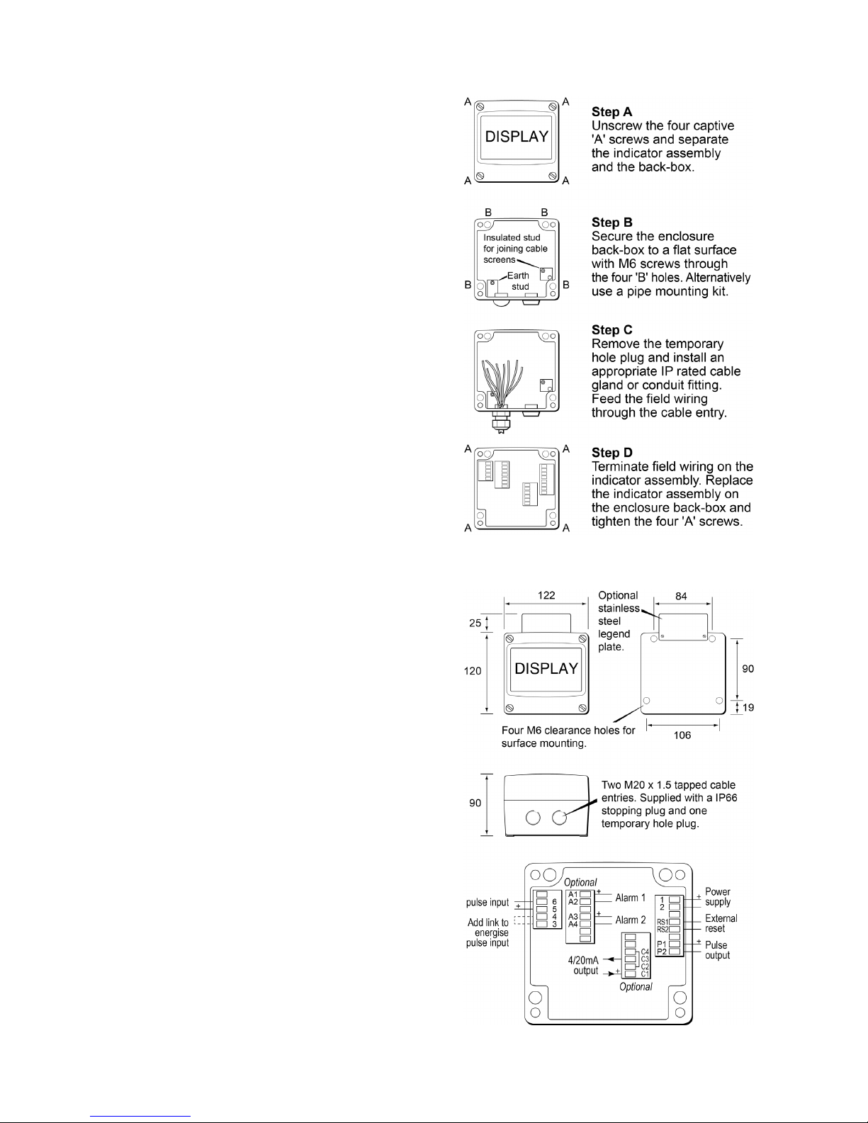
Fig 6 illustrates the instrument installation procedure.
A. Remove the Tachometer assembly by
unscrewing the four captive 'A' screws.
B. Mount the enclosure back-box on a flat surface
and secure with screws or bolts through the four
'B' holes. Alternatively use one of the pipe or
panel mounting kits which are available as
accessories.
C. Remove the temporary hole plug and install an
appropriate IP and temperature rated M20 x
1.5mm cable gland or conduit fitting. If two
entries are required, the supplied IP66 stopping
plug should be replaced with an appropriate IP
and temperature rated M20 x 1.5mm cable gland
or conduit fitting.
D. Connect the field wiring to the terminals as
shown in Fig 7. Replace the instrument
assembly on the back-box and evenly tighten the
four 'A' screws.
Fig 6 BA314G installation procedure
Fig 7 Dimensions and terminal connections
15
Page 16
5.3 EMC
The BA314G complies with the requirements of the
European EMC Directive 2014/30/EU. For specified
immunity all wiring should be in screened twisted
pairs, with the screens earthed at one point in the safe
area.
5.4 Units of measurement and tag marking
on scale card.
The Tachometer's units of measurement and tag
information can be shown on a scale card which
slides into the instrument.
New Tachometers are supplied with a printed scale
card showing the requested units of measurement
and tag information. If this information is not supplied
when the instrument is ordered, a blank scale card will
be fitted which can easily be marked on-site with a dry
transfer or a permanent marker. Custom printed scale
cards are available from BEKA associates as an
accessory.
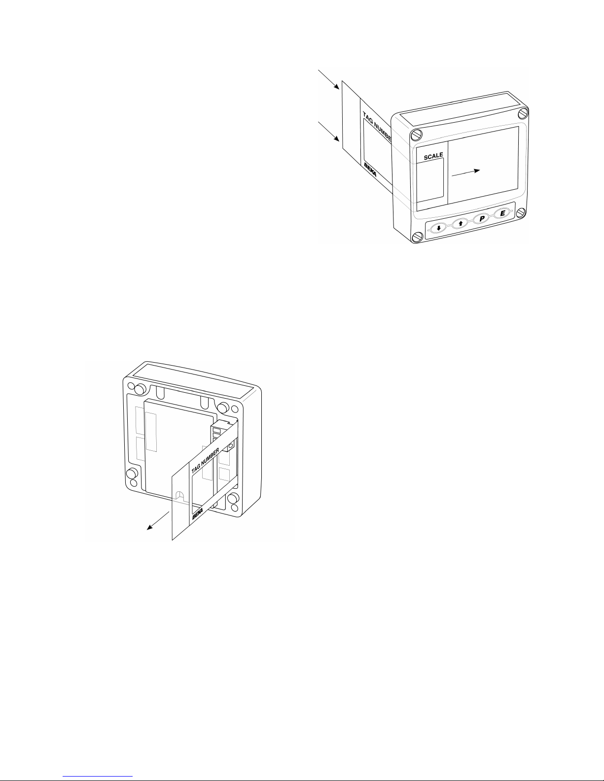
To remove the scale card from a Tachometer carefully
pull the transparent tab at the rear of the instrument
assembly away from the assembly as shown in
Fig 8a.
Fig 8a Removing scale card
To replace the scale card carefully insert it into the slot
on the right hand side of the input terminals as shown
in Fig 8b. Force should be applied evenly to both
sides of the scale card to prevent it twisting. The
card should be inserted until about 2mm of the
transparent tab remains protruding.
Fig 8b Inserting scale card into the
instrument assembly.
16
Page 17
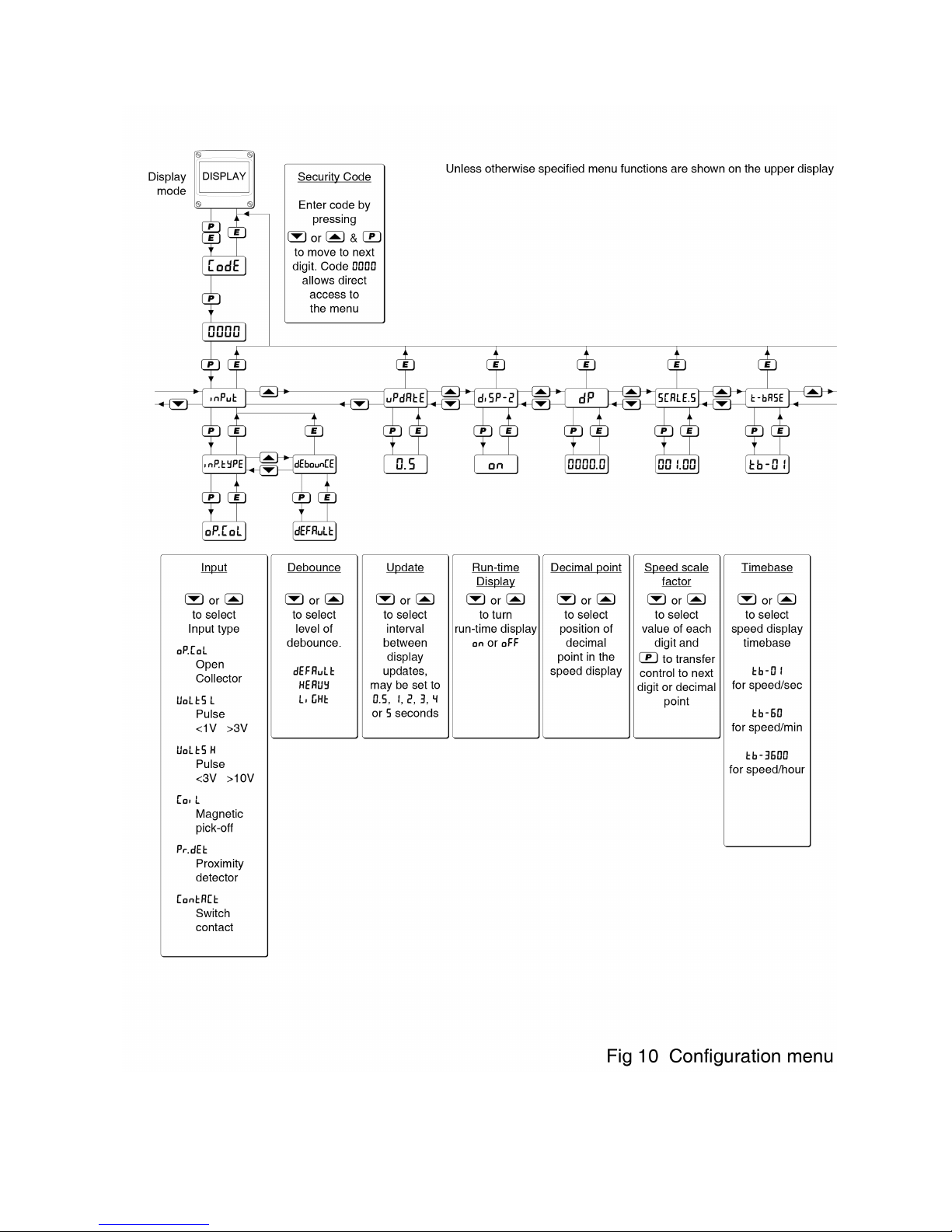
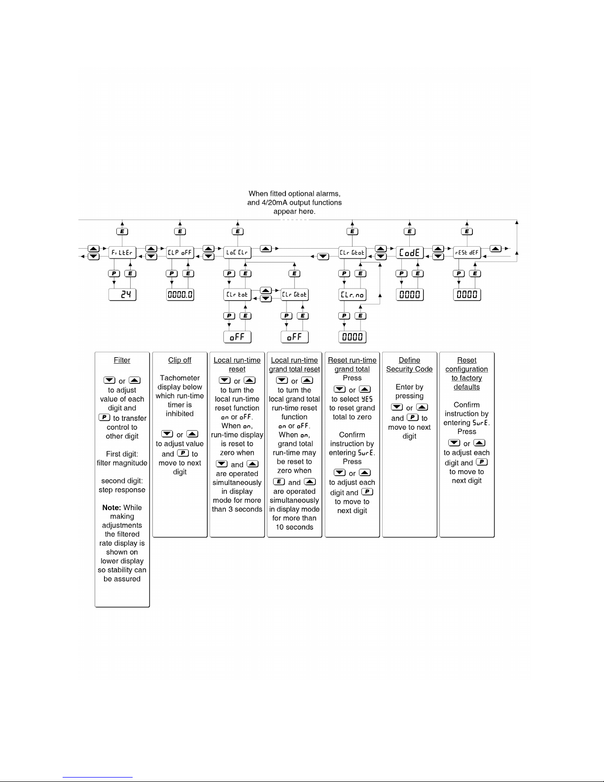
6.0 CONFIGURATION & CALIBRATION
The BA314G Tachometer is configured and calibrated
via four front panel push buttons. All the
configuration functions are contained in an easy to
use intuitive menu that is shown diagrammatically in
Fig 10.
Each menu function is summarised in section 6.3 of
this manual and each summary includes a reference
to more detailed information.
When factory fitted optional alarms, pulse and 4/20mA
outputs are included, additional functions appear in
the configuration menu, which are described
separately in section 9.
All new Tachometer are supplied calibrated as
requested at the time of ordering. If calibration is not
requested, the Tachometer will have default
configuration as shown in the following table, but can
easily be re-configured on-site.
Function Display Default
Input inP . tYPE oP . CoL
Debounce dEbounCE dEFAuLt
Update uPdAtE 0 . 5
Run-time display di5P-2 on
Decimal point (speed) dP 00 00
. 0
Speed scale factor 5CALE . 5001 . 00
Timebase t-bA5E tb-60
Filter FiLter 24
Clip-off CLP-oFF 0000 . 0
Local run-time reset clr tot oFF
Local grand total
run-time reset. Clr gtot oFF
Security code CodE 0000
6.1 Calibration structure
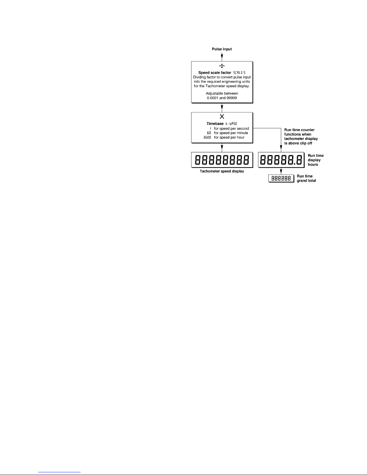
Fig 9 shows the BA314G calibration structure.
The pulse input is divided by 5CALE.5 to provide the
required Tachometer speed display in engineering
units. e.g. if a sensor monitoring a rotating shaft
generates 18 pulses per revolution, to produce a
display in revolutions 5CALE.5 should be set to 18.0.
The timebase t-bA5E is a multiplying factor that
determines whether the Tachometer displays speed
per second, per minute or per hour.
The Tachometer incorporates a run-time counter that
displays the time in hours that the speed of the
monitored machinery has been equal to or greater
than the Clip-off value.
Fig 9 Calibration structure
6.2 Accessing configuration functions
Throughout this manual push buttons are shown as
&, *, ( and ). Legends displayed by the
instruments are shown in a seven segment font as
they appear on the Tachometers e.g. inPut and
uPdAtE.
Access to the configuration menu is obtained by
operating the ( + ) push buttons simultaneously.
If the instrument is not protected by a security code
the first parameter inPut will be displayed. If a
security code other than the default code 0000 has
already been entered, the instrument will display
CodE. Press ( to clear this prompt and enter the
security code for the instrument using the & or *
push button to adjust the flashing digit, and the (
push button to transfer control to the next digit. If
the correct code has been entered pressing ) will
cause the first parameter inPut to be displayed. If
an incorrect code is entered, or a push button is not
operated within ten seconds, the instrument will
automatically return to the display mode.
All configuration functions and prompts are shown
on the upper eight digit display.
Once within the configuration menu the required
parameter can be selected by scrolling through the
menu using the & or * push buttons. The
configuration menu is shown diagrammatically in
Fig 10.
When returning to the display mode following
reconfiguration, the Tachometer will display dAtA
followed by 5AVE while the new information is stored
in permanent memory.
17
Page 18

6.3 Summary of configuration functions
This section summarises all the configuration
functions. When read in conjunction with Fig 10 it
provides a quick aid for configuring the Tachometer. If
more detail is required, each section contains a
reference to a full description of the function.
Display Summary of function
inPut Input
Contains sub-menu with two
functions:
inP
. tYPE Select Input type
dEbounCE Set debounce
See section 6.4
inP . tYPE
Configures the Tachometer to
accept one of six types of input:
oP
. CoL Open collector *
VoLt5 L Voltage pulse <1 >3V
VoLt5 H Voltage pulse <3 >10V
CoiL Magnetic pick-off
Pr
. dEt Proximity detector *
ContACt Switch contact *
* Link terminals 3 & 4
See section 6.5
dEbounCE
Defines level of input debounce
applied to the pulse input to prevent
false counting, three levels are
selectable:
dEFAuLt
heavy
LiGHt
See section 6.6
uPdAtE Display update interval
Defines the interval between display
updates from 0.5 to 5 seconds.
See section 6.7
di5P-2 Run-time display
Turns the lower display, which shows
run-time in hours, on or oFF.
See section 6.8
Display Summary of function
dP Decimal points
Defines the position of the decimal
point in the Tachometer speed
display.
See section 6.9
5CALE
. 5 Speed scale factor
5CALE.5 is a dividing factor,
adjustable between 0.0001 and
99999, that converts the pulse input
into the required Tachometer speed
display.. e.g. If a sensor monitoring a
rotating shaft generates 18 pulses
per revolution, to produce a
Tachometer speed display in
revolutions 5CALE.5 should be set to
18.0.
See section 6.10
t-bA5E Timebase
Selectable multiplier allowing
Tachometer speed display to be in
units per second, per minute or per
hour.
Select:
tb-01 per second
tb-60 per minute
tb-3600 per hour
See section 6.11
FiLtEr Display filter
Adjustable digital filter that reduces
the noise on the Tachometer speed
display, comprising two parameters
each adjustable between 0 and 9.
The first digit defines the amount of
filtering applied to the display, the
second the deviation from the
displayed value at which the filter
will be overridden and the
Tachometer display will move rapidly
to the new value.
See section 6.12
CLP-oFF Clip-off
Clip-off is the Tachometer speed
display threshold below which the
run-time clock is inhibited.
See section 6.13
18
Page 19

Display Summary of function
LoC clr Local reset
Contains sub-menu with two
functions enabling the run-time
display and grand total run-time to be
reset to zero via the front panel push
buttons when the Tachometer is in the
display mode.
See section 6.14
clr tot
When ‘on’ is selected, operating
the & and * buttons
simultaneously for more than three
seconds in the display mode
resets the run-time display to zero.
See section 6.15
clr gtot
When on is selected, operating the
) and * buttons simultaneously
for more than 10 seconds in the
display mode resets the run-time
grand total to zero.
See section 6.16
Display Summary of function
CLr Gtot Resets grand total run-time to
zero.
This function resets the grand total
run-time to zero from within the
configuration menu when CLr YE5 is
selected, and 5urE is entered to
confirm the instruction.
Note: Once reset, the original grand
total can not be recovered.
See section 6.17
CodE Security code
Defines a four digit alphanumeric
code that must be entered to gain
access to the configuration menu.
Default code 0000 disables the
security function and allows
unrestricted access to all
configuration functions.
See section 6.18
r5Et
deF Reset to factory defaults
Returns the Tachometer to the
factory defaults shown in section 6.0
To prevent accidental use the
request must be confirmed by
entering 5urE before the reset will
be executed.
See section 6.19
19
Page 20
20
Page 21
21
Page 22

6.4 Input: inPut
The Input function contains two sub-functions
inP
. tYPE and dEbounCE which configure the
Tachometer input and define the amount of input
noise rejection.
6.5 Input type: inP
. tYPE
inP
. tYPE is a sub-menu in the inPut function which
defines the type of input sensor or input pulse with
which the Tachometer will function. To check or
change the type of input, select inPut in the main
configuration menu and press ( which will reveal the
inP
. tYPE prompt, pressing ( again will show the
present type of input. If set as required press )
twice to return to the configuration menu, or
repeatedly press the & or * button until the
required type of input is displayed and then press )
twice to return to the configuration menu.
One of following six types of input may be selected:
Switching
thresholds
Low High
oP . CoL Open collector
2
210k
VoLt5L Voltage pulse low
1
13V
VoLt5H Voltage pulse high
1
310V
CoiL Magnetic pick-off 0 40mV
Pr
. dEt Proximity detector
2
1.2 2.1mA
ContACt Switch contact
2
100 1000
Notes:
1 Maximum voltage input +30V.
2 For sensors that require energising i.e.
proximity detectors, switch contacts and
open collectors, terminals 3 & 4 of the
Tachometer should be linked together.
3 To count correctly, the input pulse must fall
below the lower switching threshold and rise
above the higher switching threshold.
4 See section 6.6 for the typical maximum
operating frequency.
6.6 Debounce: dEbouncE
dEbouncE is an adjustable sub-menu in the inPut
function which prevents the Tachometer miscounting
when the input pulse has noisy edges, such as those
resulting from a mechanical contact closing and
bouncing. Three levels of protection may be
selected and the amount of debounce applied
depends upon the type of Tachometer input that has
been selected in the inP
. tYPE function.
The following table shows the minimum time that the
input pulse must be continuously above the upper
input switching threshold and continuously below the
lower switching threshold to ensure that the
Tachometer processes the input pulse. Input
switching thresholds are shown in section 6.5.
De-bounce
level
Min input pulse width
Type of Input
Contact All others
Default 1600µs 40µs
Heavy 3200µs 350µs
Light 400µs 5µs
The Tachometer’s maximum counting frequency
depends upon the debounce level selected, the
shape of the input pulse and its amplitude. The
following table assumes a square wave input and is
only for guidance. The maximum operating
frequency will be lower if the input pulses have
sloping edges and the pulse amplitude only slightly
exceeds the input switching thresholds.
ONLY FOR GUIDANCE
Debounce
level
Max counting frequency
Type of input
Contact All others
Default 150Hz 5kHz
Heavy 75Hz 1kHz
Light 500Hz 20kHz
The dEbouncE function is a sub-menu located in the
inPut function. Select inPut in the configuration
menu and press ( which will reveal the inP
. tYPE
prompt, press the & or * button to select
dEbouncE followed by ( to reveal the existing
setting. Pressing the & or * button will scroll
through the three levels. When the required level
has been selected, pressing ) twice will enter the
selection and return the display to the inPut prompt
in the configuration menu.
22
Page 23

6.7 Display update interval: uPdAtE
If the Tachometer display is likely to change rapidly, a
longer interval between display updates may simplify
reading the display. This function allows one of six
different display intervals between 0.5 and 5 seconds
to be selected. The selected display update interval
does not affect the update time of any other
instrument function.
To adjust the update interval select uPdAtE from the
configuration menu and press ( to reveal the current
time. Pressing the & or * button will scroll through
the six times. When the required interval has been
selected press ) to enter the selection and return to
the configuration menu.
6.8 Run-time display: di5P-2
This function turns the run-time display on or off,
although the run-time timer continues to function when
the display is off.
To check the status of the run-time display, select
di5P-2 from the configuration menu and press
( that will reveal if the run-time display is on or oFF.
The setting may be changed by pressing the & or *
button followed by the ) button to enter the selection
and return to the configuration menu.
6.9 Position of the decimal points: dP
This function positions the decimal point in the
Tachometer speed display. To adjust select dP from
the configuration menu and press (. The
Tachometer display will be activated and identified by
the display annunciator as RATE. The decimal point,
which may be positioned between any of the digits or
may be absent is positioned by operating the & or
* push button. When set as required enter the
setting and return to the configuration menu by
operating the ) button.
6.10 Speed scale factor: 5CALE
. 5
5CALE.5 is a dividing factor adjustable between 0.0001
and 99999 that enables the Tachometer speed display
to be in the required engineering units. e.g. If a
sensor monitoring a rotating shaft generates 18
pulses per revolution, to produce a Tachometer speed
display in revolutions 5CALE.5 should be set to 18.0.
The units of the Tachometer speed display are pulses
per unit of time. The unit of time is the timebase of the
instrument which is determined by t-bA5E which is
described in section 6.11.
To check or change the speed scale factor select
5CALE
. 5 from the configuration menu and press (
which will reveal the existing value with one digit
flashing. The value of the flashing digit may be
changed by pressing the & or * button.
When this digit has been adjusted as required,
pressing ( will transfer control to the next digit.
When all the digits have been adjusted pressing
( will transfer control to the decimal point which
may be positioned between any of the digits, or may
be omitted by moving it to the right of the least
significant digit. When the required speed scale
factor has been entered, press ) to return to the
5CALE
. 5 prompt in the configuration menu.
6.11 Timebase: t-bA5E
The timebase multiplies the Tachometer speed
display by 1, 60 or 3,600 depending upon whether
the Tachometer is required to display speed per
second, per minute or per hour. e.g. RPS, RPM or
RPH. See Fig 9.
To check or change the timebase, select t-bA5E
from the configuration menu and press ( which will
reveal the current setting. Pressing the & or *
button will scroll through the three options:
tb-1 speed per second
tb-60 speed per minute
tb-3600 speed per hour
When the required multiplier is displayed press )
to return to the t-bA5E prompt in the configuration
menu.
6.12 Display filter: FiLtEr
The digital display filter has two independent
adjustable parameters enabling the Tachometer
speed display response to be tailored for optimum
performance. The filter parameters are controlled by
a two digit number. The first digit defines the
amount of filtering applied to the display as shown
below.
First digit Filter time constant
seconds
0X 0
1X 1.3
2X 4.3
3X 6.5
4X 8.7
5X 11.3
6X 15.7
7X 20.9
8X 25.2
9X 31.5
23
Page 24

The second digit defines the deviation from the
displayed speed at which the filtering defined by the
first digit will be overridden and the Tachometer speed
display will move rapidly to the new value.
Second
digit
Magnitude of input
step change which
will override the filter
and move the speed
display rapidly to the
new value..
X0 Off
X1 1%
X2 2%
X3 4%
X4 8%
X5 12%
X6 16%
X7 24%
X8 32%
X9 64%
By careful adjustment of the two parameters a stable
display with an acceptable input step response can be
obtained for most applications.
During commissioning it is recommended that initially
the second digit is set to 0 (off) and the first digit is
adjusted to provide an acceptable Tachometer display
stability. The second digit should then be increased
until the selected step size is greater than the noise
on the display, at which setting the Tachometer speed
display will become stable. These will be the optimum
filter parameters for acceptable Tachometer speed
display stability and a fast response to a large speed
change of the monitored machinery.
To check or change the filter select FiLtEr in the
configuration menu and press ( which will reveal the
current settings with the first digit flashing. Pressing
the & or * button will change the flashing digit and
( will transfer control to the second digit. While
making adjustments the filtered Tachometer display is
shown on the lower display in place of run-time so that
stability can be assessed while adjustments are being
made. When set as required, press the ) button to
enter the revised parameters and return to the FiLtEr
prompt in the configuration menu.
6.13 Clip-off: CLP oFF
Clip-off determines the displayed speed at which the
run-time counter starts to function, below this
threshold the run-time counter does not function. If
the run-time counter is required to operate whenever
the Tachometer is powered, clip-off should be set to
zero.
If the run-time display is not being used it is not
necessary to enter a clip-off value - see 6.8.
To check or change the clip-off threshold select
CLP oFF from the configuration menu and press
( which will reveal the current setting. The
threshold is shown in the units already selected for
the Tachometer speed display with one digit flashing.
The value of the flashing digit may be adjusted by
pressing the & or * button, when set as required
pressing ( will transfer control to the next digit.
When all the digits have been adjusted, press the
) button to enter the revised threshold and return
to the CLP oFF prompt in the configuration menu.
When the Tachometer speed display falls below the
clip-off threshold, the HOLD annunciator will be
activated and the run-time clock will be stopped.
Note:
To avoid confusion, when the speed scale
factor 5CALE
. 5, timebase t-bA5E, or the
position of the speed display decimal point dp
are changed, clip-off will automatically be
reset to zero. A new clip-off threshold must be
entered after any of these changes have been
made.
6.14 Local reset: LoC clr
The Local reset function contains two sub-functions
clr tot and clr gtot which when enabled allow the
run-time display and grand total run-time to be reset
to zero via the instrument push buttons while the
Tachometer is in the display mode.
6.15 Local run-time reset: clr tot
clr tot is a sub-menu in the LoC clr function
which when activated allows an operator to reset the
run-time display to zero while the Tachometer is in
the display mode by operating the & & * push
buttons simultaneously for more than three seconds.
Select LoC clr in the configuration menu and press
( which will reveal the clr tot prompt, operate (
again which will show if the local run-time reset is on
or oFF. If set as required operate the ) button
twice to return to the configuration menu, or the &
or * button to change the setting followed by the
) button twice to enter the change and return to
the LoC
clr prompt in the configuration menu.
Note:
The run-time display may also be reset to zero
remotely by connecting terminals RS1 and
RS2 together for more than one second. See
sections 3.5; 4.1.8 and 4.2.8 of this manual.
24
Page 25

6.16 Local grand total run-time reset: clr gtot
The grand total run-time is a separate timer that
functions in parallel with the run-time display, but is
not zeroed when the run-time display is reset to zero.
The run-time grand total may be viewed in the display
mode by pressing the ) and * buttons
simultaneously.
Clr gtot is a sub-menu in the LoC clr function
which when activated allows an operator to reset the
grand total run-time to zero while the Tachometer is in
the display mode by operating the ) and * push
buttons simultaneously for more than ten seconds.
See section 2.2
To check or change the function select LoC clr in the
configuration menu and press ( which will reveal the
clr tot prompt. Using the & or * button select
clr gtot and press ( which will show if the local
grand total reset is on or oFF. If set as required
operate the ) button twice to return to the
configuration menu, or the & or * button to change
the setting followed by the ) button twice to enter
the change and return to the LoC clr prompt in the
configuration menu.
Note:
Once reset, the grand total run-time can not be
recovered.
6.17 Grand total run-time reset from within
the configuration menu: Clr
Gtot
The grand total run-time is a separate timer that is
incremented in parallel with the run-time display, but is
not zeroed when the run-time display is reset to zero.
The grand total may be viewed in the display mode by
pressing the ) and * buttons simultaneously.
The grand total can be reset to zero from within the
configuration menu using this Clr
Gtot function.
To zero the grand total from within the configuration
menu select Clr
Gtot and press ( which will cause
the instrument to display Clr
. no with no flashing.
Press the & or * push button until Clr
. YE5 is
displayed and then press ( which will result in a
0000 prompt being displayed with the first digit
flashing. This is a request for the instruction to be
confirmed by entering 5urE using the & or * button
to adjust the flashing digit and the ( button to move
control to the next digit. Pressing ) will then reset
the grand total to zero and return the Tachometer to
the configuration menu.
Note:
Once reset, the grand total run-time can not be
recovered.
6.18 Security code: CodE
Access to the instrument’s configuration menu may
be protected by a four digit security code which must
be entered to gain access. New instruments are
configured with the default security code 0000 which
allows unrestricted access to all configuration
functions.
To enter a new security code select CodE from the
configuration menu and press ( which will cause
the Tachometer to display 0000 with one digit
flashing. The flashing digit may be adjusted using
the & or * push button and the ( button to
transfer control to the next digit. When all the digits
have been adjusted press ) to return to the CodE
prompt. The revised security code will be activated
when the Tachometer is returned to the display
mode.
Please contact BEKA associates sales department if
the security code is lost.
6.19 Reset configuration to factory defaults:
r5Et Def
r5Et
Def resets the Tachometer configuration to the
factory default configurations shown in sections 6.0.
To reset the Tachometer to the factory default
configurations select r5Et def from the configuration
menu and press ( which will result in the
instrument displaying 0000 with the first digit
flashing. To confirm the instruction 5urE should be
entered. Using the & or * button set the first
flashing digit to 5 and press ( which will transfer
control to the second digit which should be set to u.
When 5urE has been entered pressing the )
button will reset all the configuration functions and
return the instrument to the display mode.
25
Page 26
6.20 Pulse output
All BA314G Tachometers have an isolated open
collector pulse output having the following
parameters:
Ron = 60 + 3V
Roff = 1M
Imax = 10mA
The output pulse may be a synchronous duplicate of
the input pulse or may be scaled and the pulse length
extended.
6.20.1 Intrinsic safety
The pulse output is an optically isolated separate
intrinsically safe circuit that has zero output safety
parameters. The output therefore complies with the
requirements for simple apparatus. This allows pulse
output terminals P1 and P2 to be connected to any
intrinsically safe circuit protected by a certified Zener
barrier or galvanic isolator providing the output
parameters do not exceed:
Uo = 28V dc
Io = 200mA
Po = 0.84W
The equivalent capacitance and inductance of the
pulse output are both zero which allows the maximum
permissible cable parameters specified by the
certificate for the Zener barrier or galvanic isolator
powering the pulse output circuit to be used.
6.20.2 System design
The Tachometer pulse output is a passive circuit i.e.
not powered, but it is totally isolated from all other
Tachometer circuits. Subject to complying with
intrinsic safety interconnection requirements, the
terminals P1 and P2 may be connected to another
instrument which will accept an open collector input.
The pulse output may also be transferred to the safe
area via a galvanic isolator or a Zener barrier.
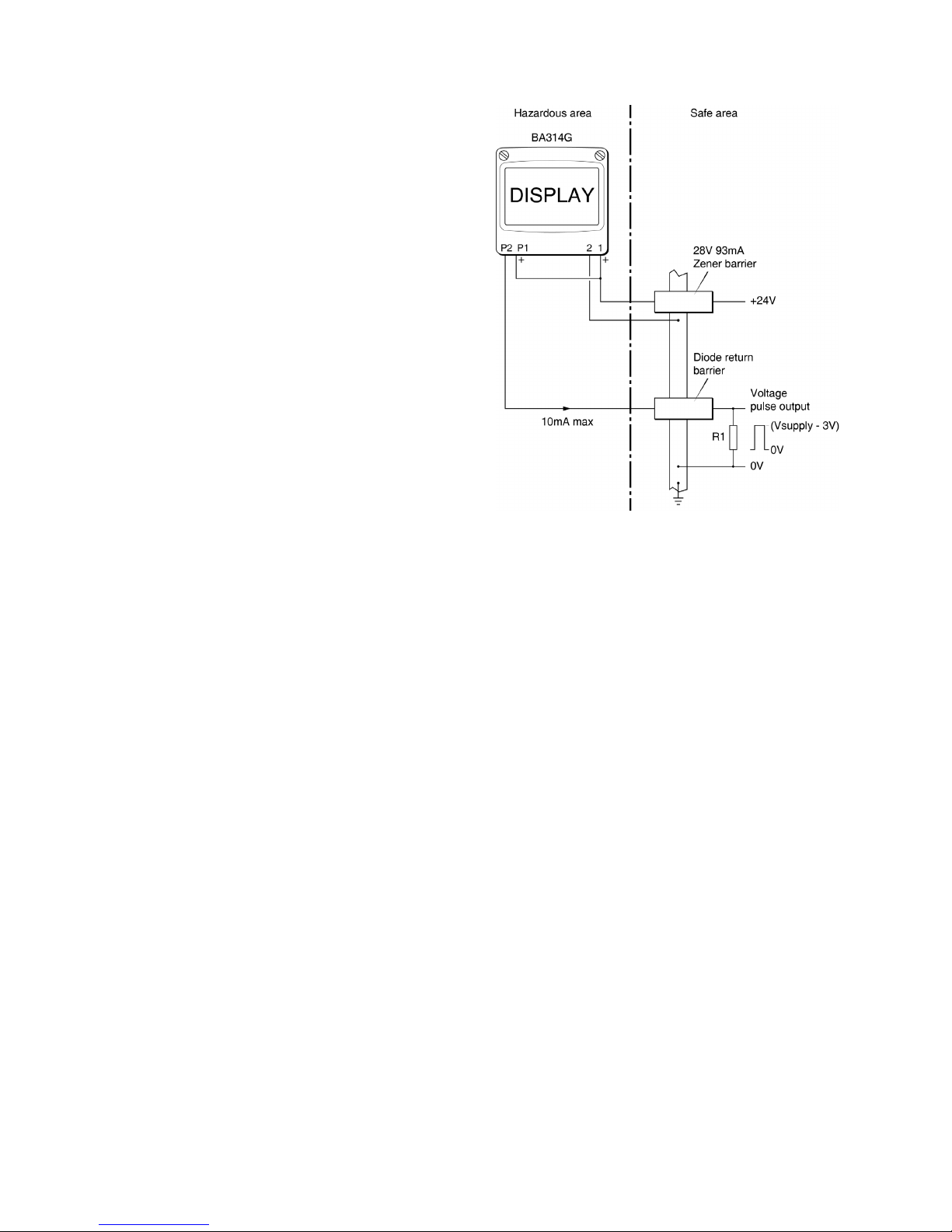
Fig 11 shows how a 2-channel Zener barrier may be
used to produce a voltage pulse in the safe area that
could be used to drive a safe area tachometer. The
positive terminal of the pulse output circuit P1 is
connected to the BA314G Tachometer’s positive
supply terminal 1 at the instrument. When an output
pulse occurs and the open collector 'closes', P2 is
connected to P1 and a pulse output current flows
through the diode return barrier to resistor R1 in the
safe area. The current flowing in the circuit is
determined by resistor R1 which should be chosen to
limit the output current to less than 10mA. For a 24V
supply R1 should therefore be greater than 2,200
Fig 11 Transferring pulse output to safe area using
Zener barriers
6.20.3 Configuration
The pulse output configuration sub-menu PuL5E
. oP
is shown in Fig 12. .
The pulse output sub-menu allows the source of the
output pulse to be selected in the 5ourCE sub-
function. For re-transmission applications the
output pulse may be a synchronous duplicate of the
input pulse by selecting dirECt in the 5ourCE sub-
function.
When 5CALEd is selected, two additional functions,
diVidE and durAtion are introduced into the sub-
menu enabling the input pulse frequency to be
divided to produce the output pulse frequency, and
the output pulse width (duration) to be lengthened.
6.20.4 Access Pulse output sub-menu: PuL5E
. oP
Access the Tachometer configuration menu as
described in section 6.2. Using the & and * push
buttons scroll though the menu until PuL5E
. oP is
displayed, pressing ( will then access the pulse
output sub-menu which is shown in Fig 12.
26
Page 27
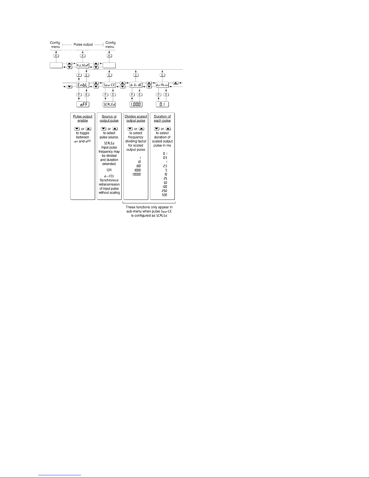
Fig 12 Pulse output configuration sub-menu
6.20.5 Enable pulse output: EnbL
This function allows the pulse output to be disabled or
enabled without altering any of the pulse output
parameters. Using the & or * push button select
EnbL in the pulse output sub-menu and press ( to
reveal the existing setting on or oFF. The function can
be changed by pressing the & or * push button
followed by the ) button to return to EnbL.
6.20.6 Source of output pulse: 5ourCE
The output pulse may be derived from:
dirECt Synchronously re-transmitted
input pulse.
Output pulse is a duplicate of the
Tachometer input pulse.
5CALEd Input pulse scaled prior to re-
transmission.
Input pulse frequency may be
divided to produce output pulse
with defined duration by the
diVidE and durAtion functions.
Using the & or * push button select 5ourCE in the
pulse output sub-menu and press ( to reveal the
existing pulse source. The source can be changed
by pressing the & or * push button followed by
the ) button to return to 5ourCE prompt.
6.20.7 Divide output pulse frequency: diVidE
When 5CALEd is selected in the 5ourCE function
described in section 6.20.6, the output pulse
frequency is the Tachometer input pulse frequency
divided by one the following:
1
10
100
1000
10000
Using the & or * push button select diVidE in the
pulse output sub-menu and press ( to reveal the
existing divisor. The value can be changed by
pressing the & or * push button to select the
required value followed by the ) button to return to
diVidE prompt.
Note: This function only appears in the pulse
output sub-menu when 5CALEd is selected in
the 5ourCE function.
27
Page 28

6.20.8 Define output pulse width: durAtion
When 5CALEd is selected in the 5ourCE function as
described in section 6.20.6, the output pulse width in
milliseconds is defined by this function. One of 11
pulse widths may be selected:
0
. 1
0
. 5
1
2
. 5
5
10
25
50
100
250
500
Using the & or * push button select durAtion in
the pulse output sub-menu and press ( to reveal the
existing pulse duration. The value can be changed by
pressing the & or * push button to select the
required value followed by the ) button to return to
durAtion prompt.
Note: This function only appears in the pulse output
sub-menu when 5CALEd is selected in the
5ourCE function.
6.20.9 Pulse storage
If the diVidE and durAtion functions are configured
such that the output pulse frequency with the specified
pulse width can not be output in real time, the
generated pulses will be stored and transmitted at the
maximum possible speed.
When the total display is reset to zero or the power
supply to the Tachometer is disconnected or turned
off, any stored pulses will not be retained.
28
Page 29

7. CONFIGURATION EXAMPLE
In this example a BA314G Tachometer is connected to
a proximity detector producing 105 pulses per
revolution.
The BA314G is required to display rotational speed in
RPM with a resolution of one RPM. The run-time
clock is to operate when the shaft speed exceeds
5 RPM. The display is to be updated twice per
second.
For this application the operator needs to reset the
run-time display to zero from the display mode, but
should not be able to reset the grand total run-time
from the display mode. To prevent tampering the
instrument configuration menu is to be protected by
security code of 1209.
7.1 Configuration procedure
The BA314G Tachometer may be configured on-site
without disconnection from the power supply or from
the proximity detector.
Step 1 Enter the configuration menu
Enter the configuration menu by
simultaneously pressing ( and ).
Assuming a security code has not already
been entered the instrument will respond
by displaying inPut which is the first
function in the configuration menu. See
Fig 10.
Step 2 Select the type of input & debounce
With inPut displayed press ( which will
reveal the sub-menu. Using the & or *
button select inP
. tYPE and press ( to
reveal the current input. The Tachometer
is required to work with a proximity
detector so again using the & or *
button select Pr.
dEt followed by ) to
return to the inP
. tYPE prompt in the sub-
menu.
Using the & or * button select
dEbouncE from the sub-menu and press
(. Using the & or * button select
dEFAuLt which will provide moderate pulse
edge noise protection. If the Tachometer
is subsequently found to miscount the
noise rejection can be increased. Enter
the selection and return to the inPut
prompt in the configuration menu by
pressing the ) button twice.
See 6.4, 6.5 and 6.6
Step 3 Select the interval between display
updates
Using the & or * button select uPdAtE
in the configuration menu and press ( to
reveal how frequently the Tachometer
display is updated.
Using the & or * push button select
0
. 5 (0.5 seconds i.e. 2 display updates
per second). Enter the selection and
return to the uPdAtE prompt in the
configuration menu by pressing the )
button.
See 6.7
Step 4 Run-time display
Using the & or * button select di5P-2
in the configuration menu and press (
to select if the run-time display is on or
oFF. The Tachometer is required to
display run-time therefore using the &
or * button select on and press ) to
enter the selection and return to the
di5P-2 prompt in the configuration menu.
See 6.8
Step 5 Position of decimal point in speed
display.
Select dP from the configuration menu
and press (. The speed display will be
activated and identified by the Rate
annunciator. Using the & or * push
button position the decimal point to the
right of the least significant digit to give a
total display resolution of 1.
Finally press the ) button to enter the
selection and return to the dP prompt in
the configuration menu.
See 6.9
Step 6 Enter the speed scale factor
5CALE.5 is a dividing factor adjustable
between 0.0001 and 99999 that enables
the Tachometer to display speed in the
required engineering units. The speed
display timebase is determined by
t-bA5E that is adjusted in Step 7.
In this example the Tachometer speed
display is required in revolutions per
minute. The proximity detector produces
105 pulses per revolution therefore
5CALE
. 5 should therefore be adjusted to
105.0.
Using the & or * push button select
5CALE.5 from the configuration menu
and press ( to reveal the existing value
with one digit flashing. This should be
changed to 105.0 using the & or *
push button to adjust the flashing digit
and the ( button to transfer control to
the next digit and to position the decimal
point. Finally, enter the new value and
return to the 5CALE
. 5 prompt in the
configuration menu by pressing ).
See 6.10
29
Page 30

Step 7 Enter the speed timebase
The speed timebase determines if the
Tachometer displays speed per second,
per minute or per hour. In this example
revolutions per minute are required.
Using the & or * push button select
t-bA5E from the configuration menu and
press (. Again using the & or * push
button select tb-60 from the three options
which will multiply the speed display by 60.
Enter the selection and return to the
t-bA5E prompt in the configuration menu
by pressing ).
See 6.11
Step 8 Adjust the display filter
The digital display filter has two
independent adjustable parameters
enabling the rate display response to be
tailored for optimum performance. The
filter parameters are controlled by a two
digit number. The first digit defines the
amount of filtering applied to the display,
for initial configuration it is recommended it
is set to 2 which is a time constant of 4.3
seconds.
The second digit defines the deviation from
the displayed speed at which the filtering,
defined by the first digit, will be overridden
and the Tachometer speed display will
move rapidly to the new value. It is
recommended that the second digit is
initially set to 0.
After configuration both parameters may
require further adjustment to provide a
stable display with an acceptable step
response.
To allow the effect of filter changes to be
seen immediately, the live speed display is
shown on the lower display in place of runtime while the filter parameters are shown
and being adjusted on the upper display.
Using the & or * push button select
FiLtEr from the configuration menu and
press (. The first digit, which controls
the filter time constant, will be flashing and
should be set to 2 using the & or * push
buttons. The ( button will transfer control
to the second digit, which controls the step
response and should be set to 0 in the
same way. Finally, enter the selection and
return to the FiLtEr prompt in the
configuration menu by pressing ).
See 6.12
Step 9 Define clip-off
In this example the run-time clock is
required to operate when the display
speed equals or exceeds 5 RPM. The
clip-off threshold should therefore be set
to 5.
Using the & or * push button select
Clp oFF from the configuration menu.
Press ( which will reveal the current
clip-off threshold in RPM i.e. the same
units already selected for the speed
display. Adjust the display to 00005 using
the & or * push buttons to adjust the
flashing digit and the ( button to
transfer control to the next digit. Finally,
enter the new clip-off threshold and
return to the CLp-oFF prompt in the
configuration menu by pressing ).
See 6.13
Step 13 Local reset of total and grand total
Two separate functions in the LoC clr
sub-menu may be individually activated
to allow the operator to reset the run-time
display and grand total run-time from the
display mode without entering the
configuration menu.
In this example the operator is required
to reset the run-time display but not the
grand total run-time when the BA314G
Tachometer is in the display mode.
Using the & or * button select LoC clr
in the configuration menu and press (
which will reveal the sub-menu. Again
using the & or * button select the local
total reset function clr tot and press (.
This is required therefore using the & or
* button select on followed by ) to
return to the clr tot prompt in the submenu.
Using the & or * button select the
local grand total run-time reset function
clr gtot and press (. This is not
required therefore using the & or *
button select oFF. Enter the selection
and return to the Loc clr prompt in
the configuration menu by pressing the
) button twice.
See 6.15 and 6.16
30
Page 31

Step 14 Reset the grand total to zero
Before completing configuration the runtime grand total should be reset to zero.
Using the & or * button select Clr
. Gtot
in the configuration menu and press (
which will cause Clr
. no to be displayed.
Again using the & or * button select
CLr YE5 and press ( which will result in a
0000 display with one digit flashing. This is
a request for the instruction to be
confirmed by entering 5urE using the
& or * buttons to set each digit and the
( button to move control to the next digit.
Pressing ) will then reset the run-time
grand total to zero and return the
instrument to the Clr
. Gtot prompt in the
configuration menu.
See 6.17.
Step 15 Define the security code
Defining a security code prevents
unauthorised access to the configuration
menu. Using the & or * button select
CodE from the configuration menu and
press ( which will reveal 0000 with the
first digit flashing. This example requires
the security code to be 1209, using the &
or * button set the flashing digit to 1 and
press ( to transfer control to the second
digit. When all have been entered press
) to return to the main configuration
menu.
See 6.18.
Step 16 Return to the display mode
Configuration of the BA314G is now
complete. Pressing the ) button will
save the new configuration and return the
Tachometer to the display mode. The
BA314G will display dAtA followed by
5AVE while the new information is stored
in permanent memory, which will be
protected from unauthorised adjustment
by the security code.
To obtain a stable display it may be
necessary to adjust the two filter
parameters and the level of debounce
during commissioning of the Tachometer.
31
Page 32

8. MAINTENANCE
8.1 Fault finding during commissioning
If a BA314G Tachometer fails to function during
commissioning the following procedure should be
followed:
Symptom Cause Check:
No display No power supply,
or incorrect wiring.
Note: Terminals 2,
6 & RS2 are
interconnected
within the
instrument.
That there is
between 10 and
28V on terminals 1
& 2 with terminal 1
positive.
Tachometer is
receiving power but
pulse input
indicator not
rotating
No input pulses,
incorrect input
configuration,
incorrect linking of
terminals 3 & 4.
Input configuration.
Linking of
terminals 3 & 4.
That input signal
polarity is correct.
Pulse input
indicator rotating,
but incorrect speed
display
Incorrect speed
display calibration.
5CALE
. 5
t-bA5E
Pulse input
indicator rotating
but missing or
incorrect
run-time display.
Run-time display is
not activated.
Tachometer speed
display is less than
clip-off value.
Remote reset
switch contacts
closed.
di5P-2 is activated
See 6.8
If HOLD
annunciator is
activated, enter
smaller Clip-off
value. See 6.13
That ‘RESET’
annunciator is not
activated. If it is,
check reset wiring
and switch.
Unstable
Tachometer
display.
Noisy pulse input
signal.
Eliminate source of
electrical noise.
Increase debounce
and/or display filter.
See 6.12
Unable to enter
configuration
menu.
Incorrect security
code.
That the correct
security code is
being used.
See 6.18
Contact BEKA if
code is lost.
Clip-off does not
function.
Clip-off has
automatically been
reset to zero
following
calibration change.
Reconfigure
clip-off.
See 6.13
Alarms do not
function.
Alarms have been
disabled following
calibration change.
Re-enable both
alarms.
See 9.3.4
8.2 Fault finding after commissioning
ENSURE PLANT SAFETY BEFORE
STARTING MAINTENANCE
Live maintenance is permitted on
intrinsically safe equipment installed in a
hazardous area, but only certified test
equipment should be used unless a gas
clearance certificate is available.
If a BA314G Tachometer fails after it has been
functioning correctly, the following table may help to
identify the cause of the failure.
Symptom Cause Check:
No display No power supply. That there is
between 10 and
28V on terminals
1 & 2.
Pulse input
indicator not
rotating.
No input pulses. Output from
sensor.
Wiring between
sensor and
Tachometer.
Pulse input
indicator rotating,
run-time display
not functioning.
HOLD annunciator
activated.
Input below
clip-off threshold.
Adjust Clip-off
threshold.
Unstable rate
display
Noisy pulse input
signal
Locate source of
electrical noise, or
increase
debounce and
rate display filter.
If this procedure does not reveal the cause of the
fault, it is recommended that the instrument is
replaced.
8.3 Servicing
We recommend that faulty BA314G Tachometers
are returned to BEKA associates or to your local
BEKA agent for repair.
8.4 Routine maintenance
The mechanical and electrical condition of the
instrument should be regularly checked. Inspection
frequency should be adjusted to suit the
environmental conditions.
8.5 Guarantee
Instruments which fail within the guarantee period
should be returned to BEKA associates or our local
agent. It is helpful if a brief description of the fault
symptoms is provided.
8.6 Customer comments
BEKA associates is always pleased to receive
comments from customers about our products and
services. All communications are acknowledged and
whenever possible, suggestions are implemented.
32
Page 33

9. ACCESSORIES
9.1 Units of measurement & instrument
identification.
New BA314G Tachometers are supplied with a printed
scale card showing the units of measurement and tag
information specified when the instrument was
ordered. If this information was not supplied a blank
scale card will be fitted which can easily be marked
with a dry transfer or a permanent marker on-site.
Custom printed scale cards are available as
accessories and may be easily fitted as shown in
section 5.4 of this manual.
The BA314G can also be supplied with a blank or
custom laser engraved stainless steel legend plate see Fig 7. The plate, which after installation is visible
from the front of the instrument, is supplied loose with
two fixing screws for securing it to the rear of the
instrument's back-box. This plate can typically
accommodate:
1 row of 5 alphanumeric characters 10mm high
or 1 row of 6 alphanumeric characters 7mm high
or 2 rows of 10 alphanumeric characters 5mm high
9.2 Display Backlight
The BA314G Tachometer can be supplied with a
factory fitted backlight that produces green
illumination enhancing display contrast and enabling it
to be read at night or in poor lighting conditions. The
backlight is internally powered from the instrument so
that no additional wiring or intrinsically safe interface
is required, but the instrument supply current
increases to 32mA.
9.3 Alarms
The BA314G Tachometer can be supplied with
factory fitted, dual isolated solid state single pole
alarm outputs that may be independently configured.
Each may be configured as a speed or run-time
alarm with a high or low function having a normally
open or closed output. An alarm delay and alarm
silence time can be included and hysteresis may be
applied to speed alarms.
CAUTION
These alarm outputs should not be used
for critical safety applications such as a
shut down system.
When the BA314G Tachometer power supply is
turned off or disconnected, alarm outputs will open
irrespective of whether normally open or normally
closed outputs have been selected. When designing
a system an open output should therefore be chosen
for the alarm condition. Alarm annunciators on the
instrument display indicate the status of each alarm.
If an alarm delay or silence time has been selected
the annunciator will flash during the delay or silence
period.
The BA314G internal counters are up-dated and
compared with the alarm setpoint twice per second,
irrespective of the display update time selected.
This may result in an alarm being delayed for up to
half a second after speed or run-time has exceeded
the alarm setpoint.
9.3.1 Solid state output
Each alarm has a galvanically isolated single pole
solid state switch output as shown in Fig 13. The
outputs are polarised and current will only flow in
one direction. Terminals A1 and A3 should be
connected to the positive side of the supply.
Ron = less than 5 + 0.7V
Roff = greater than 1M
Note: Because of the series protection diode some
test meters may not detect a closed alarm
output
33
Page 34
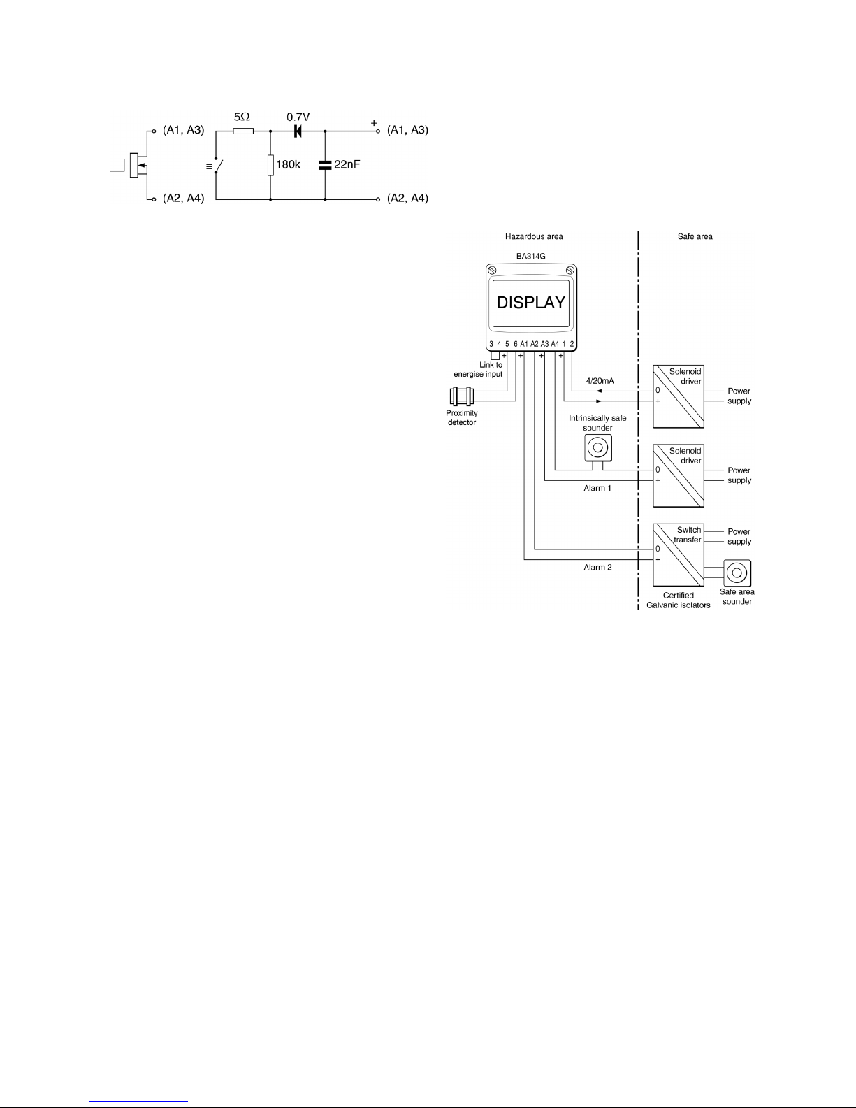
Fig 13 Equivalent circuit of each alarm output
9.3.2 Intrinsic safety
Each alarm output is a separate galvanically isolated
intrinsically safe circuit with output safety parameters
complying with the requirements for simple apparatus.
This allows the alarm output terminals A1 & A2 and A3
& A4 to be connected to almost any intrinsically safe
circuit protected by a Zener barrier or galvanic isolator
providing the output parameters of the circuit do not
exceed:
Uo 28V dc
Io 200mA
Po 0.84W
The maximum equivalent capacitance and inductance
between each set of alarm terminals is:
Ci = 22nF
Li = 4µH
To determine the maximum permissible cable
parameters Ci should be subtracted from the
maximum permitted external capacitance Co
specified by the certificate for the intrinsically safe
interface powering the alarm circuit, such as the
solenoid driver and switch transfer galvanic isolators
shown in Fig 14.
Fig 14 Typical alarm application
34
Page 35

9.3.3 Configuration and adjustment
When a BA314G is supplied with alarms the
configuration menu is extended as shown in Fig 15
which for simplicity only shows alarm AL1 configured
to operate as a speed alarm. The run-time options
are identical except that a run-time alarm can not
have hysteresis. Alarm AL2 functions are identical to
alarm AL1.
The following table summarises each of the alarm
configuration functions and includes a cross
references to more detailed information. Again only
the functions on alarm AL1 are listed.
Display Summary of function
EnbL Alarm enable
Enables or disables the alarm without
changing the alarm parameters.
See section 9.3.4
tYPE Type of alarm
Defines whether the alarm operates on the
speed or run-time display.
See section 9.3.5
5P1.5peed Alarm setpoint 1
or Adjusts the alarm setpoint. The
5P1.Hour5s alarm is activated when the speed or
run-time display equals the setpoint.
Note: 5P15 is displayed for a speed alarm
and 5P1H for a run-time alarm.
See section 9.3.6
HI
. LO Alarm function
Defines whether the alarm has a high or
low function.
See section 9.3.7
Display Summary of function
no
. nc Normally open or normally closed
output.
Determines whether the single pole
alarm output is open or closed in the
non-alarm condition.
See section 9.3.8
H5tr Hysteresis
Adjusts the alarm hysteresis. Only
available on a speed alarm.
See section 9.3.9
dELA Alarm delay time
Adjusts the delay between the display
equalling the setpoint and the alarm
output being activated.
See section 9.3.10
5IL Alarm silence time
Defines the time that the alarm output
remains in the non-alarm condition
following acceptance of an alarm.
See section 9.3.11
FL5H Flash display when alarm occurs
When enabled, alternates the speed or
run-time display between the value and
alarm reference Al1 or Al2 when an
alarm output is activated.
See section 9.3.12
AC5P Access setpoint
Sub-menu that enables direct access to
the alarm setpoints from the display
mode and defines a separate security
code.
See section 9.3.13
35
Page 36
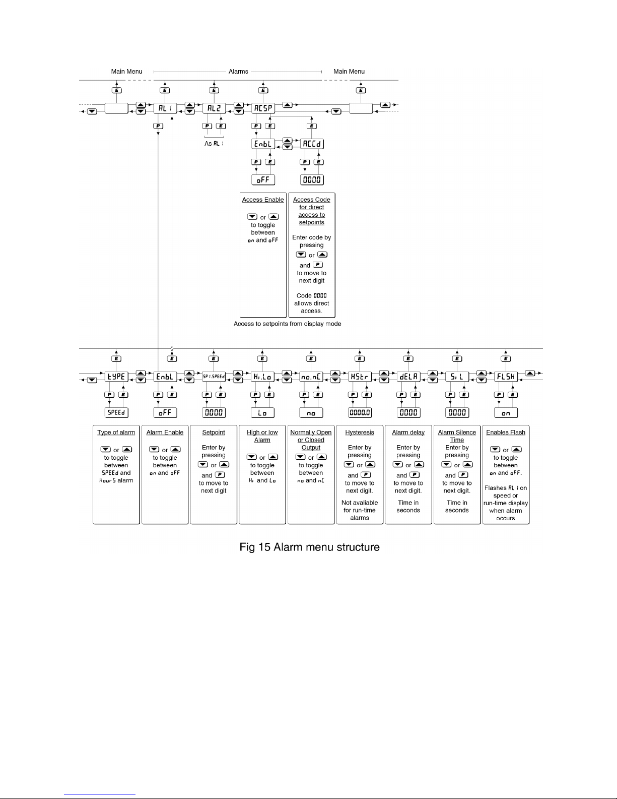
36
Page 37

9.3.4 Alarm enable: EnbL
This function allows the alarm to be enabled or
disabled without altering any of the alarm parameters.
Using the & or * push button select AL1 or AL2 from
the configuration menu and press ( to access the
alarm sub-menu. Press the & or * button until
EnbL is displayed followed by ( which will reveal if
the function is on or off. The setting can be changed
by pressing the & or * push button followed by the
)
button to return to the alarm sub-menu.
9.3.5 Type of alarm: tYPE
Alarm 1 and Alarm 2 are totally independent, both
may be speed or run-time alarms, or one may be
conditioned for speed and the other for run-time.
Using the & or * push button select tYPE from the
selected alarm sub-menu and press ( to check or
change the function. The & or * push button will
toggle the selection between 5PEEd and Hour5, when
set as required press the ) button to return to the
alarm sub-menu.
Note: When tYPE is changed, the alarm
configuration is automatically reset to the
default values and the alarm is disabled. It
must therefore be reconfigured before use.
9.3.6 Setpoint adjustment: 5P1.x & 5P2.x
The speed alarm setpoints 5P1.5peed and 5P2.5peed
may be positioned anywhere between 0000000 and
9999999, and the run-time alarm setpoint 5P1.Hour5
and 5P2.Hour5 anywhere between 0000.0 and 9999.9
hours.
All the setpoints are adjusted in the same way, for
example, to adjust the setpoint of Alarm 1 which has
been configured to operate on the speed display.
Using the & or * push button select 5P1.5peed in
the AL1 sub-menu and press ( which will reveal the
existing setpoint with one digit flashing. The required
setpoint can be entered using the & or * push
button to adjust the flashing digit and the ( button to
transfer control to the next digit. When set as
required press ) to enter the value and return to the
5P1.5peed prompt in the alarm 1 sub-menu.
9.3.7 Alarm function:
Hi . Lo
Alarm 1 and Alarm 2 are totally independent, both
may be Hi or Lo, or one may be conditioned as a Hi
alarm and the other as a Lo alarm.
Using the & or * push button select Hi
. Lo from the
selected alarm sub-menu and press ( to check or
change the function. The & or * push button will
toggle the alarm function between Hi and Lo, when
set as required, press the ) button to return to the
Hi
. Lo’ prompt in the alarm sub-menu.
9.3.8 Alarm output status: no
. nC
Each single pole alarm output may be open or
closed in the non-alarm condition. When the
BA314G or BA318E power supply is turned off or
disconnected, the alarm output(s) will open
irrespective of whether normally open or normally
closed outputs have been selected. Therefore,
when designing an alarm system normally closed nc
should be selected so that the output opens when an
alarm occurs or if the power supply fails.
Using the & or * push button select no
. nC from
the selected alarm sub-menu and press ( to check
or change the function. The & or * push button
will toggle the contact status between no and nC,
when set as required, press the ) button to return
to the no
. nC prompt in the alarm sub-menu
9.3.9 Hysteresis: H5tr
Hysteresis is only available on speed alarms so the
H5tr function only appears in the configuration submenu when alarm tYPE has been set to 5PEEd.
During configuration hysteresis is shown in the units
of 5PEED previously configured for the Tachometer
display.
Using the & or * push button select H5tr in the
selected alarm sub-menu and press ( which will
reveal the existing hysteresis with one digit flashing.
The required hysteresis can be entered using the
& or * push button to adjust the flashing digit and
the ( button to transfer control to the next digit.
When set as required press ) to enter the value
and return to the H5tr prompt in the alarm submenu.
e.g. A Tachometer configured to display a rotational
speed of 0 to 500 RPM, with a high alarm set at
400 RPM and hysteresis of 10 RPM will perform as
follows:
The high alarm will be activated when speed
equals or exceeds 400 RPM, but will not reset
until the speed falls below 390 RPM.
9.3.10 Alarm delay: dELA
This function enables activation of the alarm output
to be delayed for a fixed time following the alarm
condition occurring. The delay can be set in 1
second increments up to 3600 seconds. If a delay is
not required zero should be entered.
To adjust the delay select dELA using the & or *
push button in the selected alarm sub-menu and
press ( which will reveal the existing delay time in
seconds with one digit flashing. The required delay
time can be entered using the & or * push button
to adjust the flashing digit and the ( button to
transfer control to the next digit. When set as
required press ) to enter the value and return to
the dELA prompt in the alarm sub-menu.
37
Page 38

The alarm annunciator will start flashing immediately
an alarm condition occurs and will continue for the
delay time, after which the alarm output will be
activated and the alarm annunciator will be
permanently activated.
9.3.11 Alarm silence time: 5IL
The alarm silence function is primarily intended for
use in small installations where the alarm output
directly operates an annunciator such as a sounder.
When the alarm silence time is set to any figure other
than zero, the ( push button becomes an alarm
accept button.
After an alarm has occurred, operating the ( button
will cause the alarm output to revert to the non-alarm
condition for the configured alarm silence time. When
an alarm is silenced the alarm annunciator will flash
until the silence time expires.
To adjust the alarm silence time select 5iL using the
& or * push button in the selected alarm sub-menu
and press ( which will reveal the existing alarm
silence time in seconds with one digit flashing. The
required delay time can be entered using the
& or * push button to adjust the flashing digit and
the ( button to transfer control to the next digit.
When set as required press ) to enter the value and
return to the 5iL prompt in the alarm sub-menu.
9.3.12 Flash display when alarm occurs: FL5H
In addition to the two alarm annunciators at the
bottom left hand side of the Tachometer display which
show the status of both alarms, this function provides
an even more conspicuous indication that an alarm
condition has occurred.
When enabled, this function alternates the speed or
run-time display between the numerical value and the
alarm identification AL1 or AL2 when an alarm occurs.
Using the & or * push button select FL5H from the
selected alarm sub-menu and press ( to check or
change the function. The & or * push button will
toggle the function between oFF and on, when set as
required, press the ) button to return to the FL5H
prompt in the alarm sub-menu.
9.3.13 Access Setpoint: AC5P
This function activates a separate menu that provides
direct access to the alarm setpoints when the
Tachometer is in the display mode by simultaneously
operating the ( and * buttons. An operator can
therefore adjust the alarm setpoints without having
access to the configuration and alarm sub-menus.
Protection against unauthorised or accidental
adjustment is provided by a separate security access
code.
Using the & or * push button select AC5P from the
configuration menu and press ( to reach the
enable function EnbL. Pressing ( will reveal the
existing setting which can be toggled between on
and oFF by pressing the & or * push button.
When set as required, press the ) button to return
to the EnbL prompt from which a separate security
access code can be entered using the ACCd function
which can be selected using the & or * push
button.
To enter a new security code select ACCd from the
sub-menu and press ( which will cause the
Tachometer to display 0000 with one digit flashing.
The flashing digit may be adjusted using the
& and * push button, when set as required
operating the ( button will transfer control to the
next digit. When all the digits have been adjusted
press ) to return to the ACCd prompt. The revised
security code will be activated when the Tachometer
is returned to the display mode. Default security
access code 0000 will disable the security code
allowing direct access to the setpoints in the display
mode by pressing the ( and * buttons
simultaneously.
Please contact BEKA associates sales department if
the security code is lost.
9.3.14 Adjusting alarm setpoints from the
display mode
Access to the two alarm setpoints from the
Tachometer display mode is obtained by operating
the ( and * push buttons simultaneously as
shown in Fig 16. If the setpoints are not protected
by a security code the alarm setpoint prompt
5P1.5peed or 5P1.Hour5 will be displayed depending
upon whether a speed or run-time alarm has been
configured. If the setpoints are protected by a
security code, CodE will be displayed first. Pressing
( again will allow the alarm setpoint security
access code to be entered digit by digit using the
& or * buttons to adjust the flashing digit and the
( push button to move control to the next digit. If
the correct code is entered pressing ) will then
cause alarm setpoint prompt 5P1.5peed or 5P1.Hour5
to be displayed. If an incorrect security code is
entered, or a button is not pressed within ten
seconds, the instrument will automatically return to
the display mode. Once within the menu pressing
the & or * buttons will toggle the display between
the two alarm setpoint prompts 5P1x and 5P2x.
38
Page 39
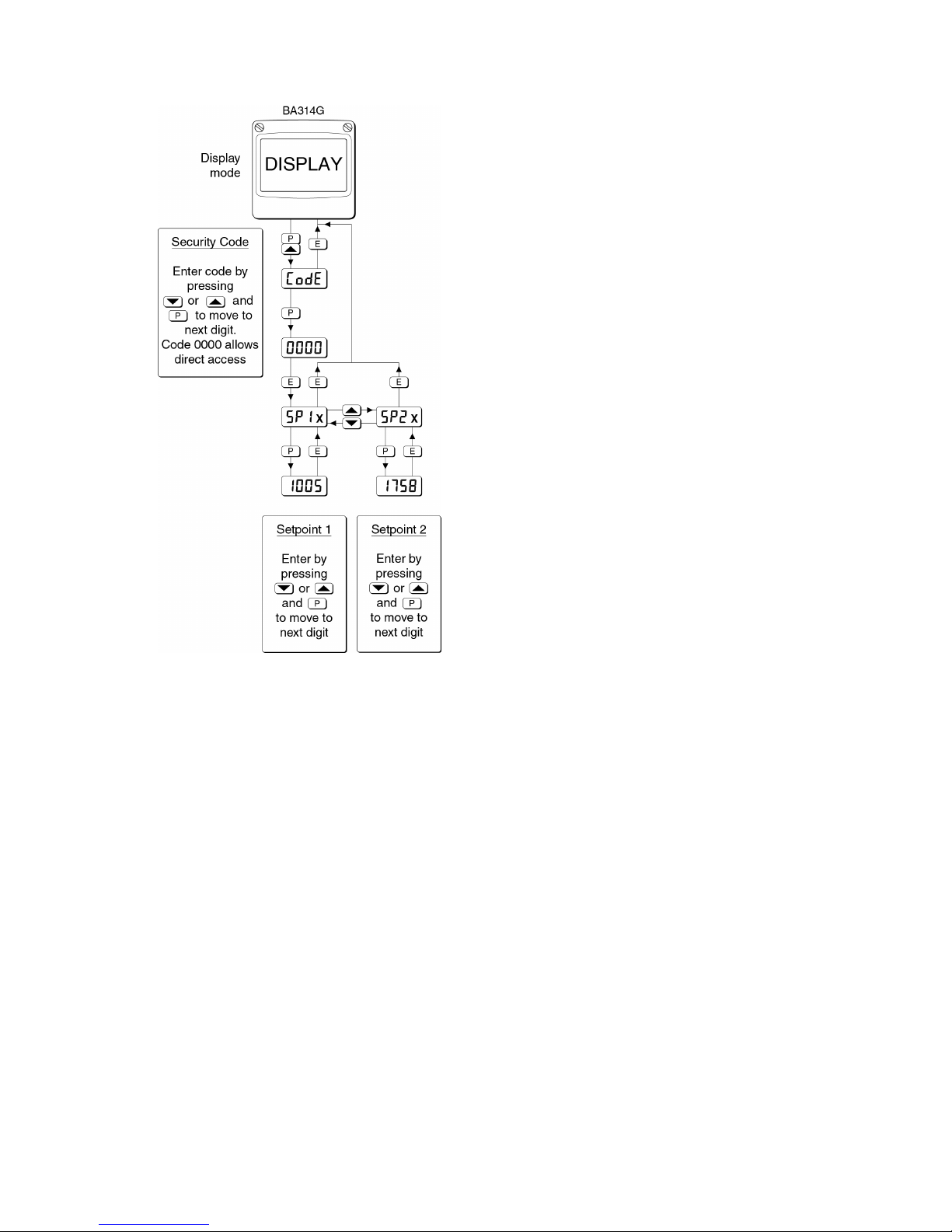
Fig 16 Setpoint adjustment from the display mode
To adjust an alarm setpoint select 5P1x or 5P2x and
press ( which will reveal the current setting. The
flashing digit of the setpoint may be adjusted using the
& or * push button and the ( button to transfer
control to the next digit. When the required setpoint
has been entered, pressing )
will return the display
to the 5P1x or 5P2x prompt from which the other
setpoint may be selected, or the instrument may be
returned to the display mode by pressing ) again.
Note: Direct access to the alarm setpoints is only
available when the menu is enabled - see
section 9.3.13
39
Page 40
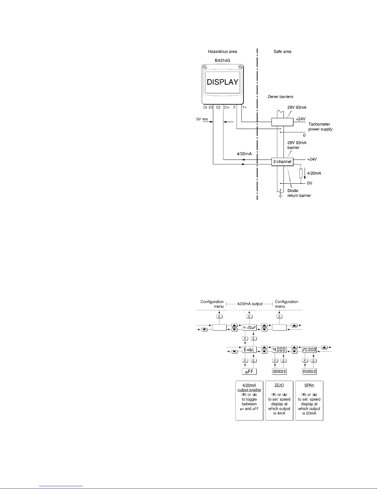
9.4 4/20mA output
The BA314G Tachometer can be supplied with a
factory fitted galvanically isolated 4/20mA output
which may be configured to represent any part of the
Tachometer speed display.
9.4.1 Intrinsic safety
The 4/20mA output has been certified as a separate
galvanically isolated intrinsically safe circuit complying
with the requirements for simple apparatus. This
allows terminals C1 and C3 to be connected to any
intrinsically safe circuit protected by a certified Zener
barrier or galvanic isolator providing the output
parameters do not exceed:
Uo = 28V dc
Io = 200mA
Po = 0.84W
The maximum equivalent capacitance and inductance
of the pulse output is:
Ci = 2.2nF
Li = 4µH
To determine the maximum permissible cable
parameters, these figures should be subtracted from
the maximum cable capacitance and inductance
specified by the certificate for the Zener barrier or
galvanic isolator powering the 4/20mA output circuit.
9.4.2 System design
The Tachometer 4/20mA output is a passive current
sink i.e. not powered, but it is totally isolated from all
other Tachometer circuits. It is effectively a 2-wire
4/20mA transmitter requiring a minimum supply of 5V
with its current being controlled by the Tachometer
speed display. Subject to complying with intrinsic
safety interconnection requirements, the terminals C1
and C3 may be connected to another instrument,
which will accept a 4/20mA transmitter input. The
4/20mA current output may also be transferred to the
safe area via a galvanic isolator or Zener barriers.
Terminals C2 and C4 are internally linked and may be
used for joining a return 4/20mA wire.
Fig 17 shows how a 2-channel Zener barrier may be
used to transfer the 4/20mA current output into the
safe area, alternatively a galvanic isolator may be
used.
Fig 17 Application of 4/20mA output
9.4.3 Configuration and calibration
When a Tachometer is supplied with an optional
4/20mA output the configuration menu is extended
as shown in Fig 18. The 4/20mA output sub-menu
is accessed via the 4-20 oP function.
The 4/20mA output is controlled by the Tachometer
speed display, the speeds corresponding to 4 and
20mA output are defined in the sub-menu.
Fig 18 4/20mA output configuration sub-menu
40
Page 41

9.4.4 Access 4/20mA output sub-menu: 4-20 oP
Access the Tachometer configuration menu as
described in section 6.2. Using the & and * push
buttons scroll though the menu until 4-20 oP is
displayed, pressing ( will then access the 4/20mA
output sub-menu which is shown in Fig 18.
9.4.5 Enable 4/20mA output: EnbL
This function allows the 4-20mA output to be enabled
or disabled without altering any of the output
parameters. Using the & or * push button select
EnbL in the 4-20 op sub-menu and press ( which will
reveal the existing setting on or oFF. The function can
be changed by pressing the & or * push button
followed by the ) button to return to EnbL prompt in
the sub-menu.
9.4.6 Display which corresponds to 4mA
output: 4
. 000
The Tachometer speed display which corresponds to
a 4.000mA output current is defined by this function.
Using the & or * push button select 4
. 000 in the
4/20mA output sub-menu and press ( to reveal the
existing speed display with one digit flashing. The
required display can be entered using the & or *
push button to adjust the flashing digit and the (
button to transfer control to the next digit. When set
as required, press ) to enter the value and return to
the 4
. 000 prompt in the 4/20mA output sub-menu.
9.4.7 Display which corresponds to 20mA
output: 20
. 000
The Tachometer display which corresponds to a
20.000mA output current is defined by this function.
Using the & or * push button select 20
. 000 in the
4/20mA output sub-menu and press ( to reveal the
existing speed display with one digit flashing. The
required display can be entered using the & or *
push button to adjust the flashing digit and the (
button to transfer control to the next digit. When set
as required, press ) to enter the value and return to
the 20
. 000 prompt in the 4/20mA output sub-menu.
Notes:
1. If the Tachometer calibration is changed the
4/20mA output will automatically be set to
3.5mA irrespective of the speed display.
The 4/20mA output should always be
reconfigured following changes to the
Tachometer configuration.
2. If the Tachometer and the 4/20mA current
sink output are powered from separate
supplies, the 4/20mA output current will
continue to flow when the Tachometer
supply fails or is turned off. Powering both
from a common supply eliminates this effect.
41
Page 42

APPENDIX 1
ATEX Dust Certification
A1.0 ATEX dust certification
In addition to ATEX certification permitting installation
in explosive gas atmospheres which is described in
the main section of this instruction manual, the
BA314G Tachometer also has ATEX dust certification.
A1.1 Zones, and Maximum Surface
Temperature.
The BA314G has been certified
Group II Category 1D Ex ia IIIC T80°C Da
Ta = -40º to 60ºC. When connected to a suitable
system it may be installed in:
Zone 20 explosive atmosphere in the form of a
cloud of combustible dust in air is
continuously present, or for long
periods or frequently.
Zone 21 explosive atmosphere in the form of a
cloud of combustible dust in air is
likely to occur occasionally in normal
operation.
Zone 22 explosive atmosphere in the form of a
cloud of combustible dust in air is not
likely to occur in normal operation, but
if it does occur, will only persist for a
short period.
Be used with dust in subdivisions:
IIIA combustible flyings
IIIB non-conductive dust
IIIC conductive dust
Having a Minimum Ignition Temperature of:
Dust cloud 120°C
Dust layer on Rate 155°C
Totaliser up to 5mm thick
Dust layer on Rate Refer to
Totaliser over 5mm thick. EN 60079-14
At an ambient temperature between -40 and +60°C
A1.2 Installation and maintenance
The installation requirement described in this manual
for use in a gas potentially explosive atmospheres
also apply when the Tachometer is installed in a dust
potentially explosive atmosphere.
The instrument assembly should only be removed
from the enclosure back-box when dust can not
enter the instrument enclosure. Before replacing the
instrument assembly the sealing gasket should be
inspected to ensure that it is undamaged and free
from foreign bodies.
It is good practice to prevent dust accumulating on
the Tachometer enclosure. If this can not be
avoided, care should be taken to ensure that the
layer thickness does not exceed 5mm for dusts
having a minimum ignition temperature of 155°C.
42
Page 43

APPENDIX 2
IECEx certification
A2.0 The IECEx Certification Scheme
IECEx is a global certification scheme for explosion
protected products which aims to harmonise
international certification standards. For additional
information about the IECEx certification scheme and
to view the BEKA associate certificates, please visit
www.iecex.com
A2.1 IECEx Certificate of Conformity
The BA314G Tachometer and the optional
accessories have been issued with an IECEx
Certificate of Conformity number IECEx ITS 16.0004X
which specifies the following certification codes:
Ex ia IIC T5 Ga
Ta = -40°C to 70°C
Ex ia IIIC T80°C IP66 Da
Ta = -40°C to 60°C
The specified IECEx gas and dust intrinsic safety
parameters are identical to the ATEX safety
parameters described in the main section and
Appendix 1 of this manual.
The IECEx certificate may be downloaded from the
BEKA associate ot the IECEx websites or requested
from the BEKA sales office.
A2.2 Installation
The IECEx intrinsic safety parameters are identical to
the ATEX safety parameters described in the main
section of this manual and both refer to the same
standards. Therefore the ATEX installation
requirements specified in section 5 of this manual may
be used for IECEx installations, but the local code of
practice should also be consulted.
43
Page 44

APPENDIX 3
ETL & cETL certification for installations in USA
and Canada.
A3.0 cETL Mark
For installations in the USA and Canada, the BA314G
Tachometer has ETL and cETL intrinsic safety and
nonincendive approval, Control Number 4008610.
Copies of the Authorisation to Mark may be
downloaded from the BEKA associates website
www.beka.co.uk
or requested from the BEKA
associates sales office
A3.1 Intrinsic safety approval
The US and Canadian standards used for assessment
and certification of the BA314G are listed on the cETL
Authorisation to Mark.
Installations must comply with BEKA associates
Control Drawing CI330-52, which is attached to this
appendix.
The ETL safety parameters are the same as the ATEX
and IECEx parameters, the systems shown in
sections 3 and 4 of this manual may therefore also be
used for US and Canadian installations subject to
compliance with the local codes of practice.
ETL and cETL intrinsic safety codes
USA & Canada
CL I Div 1 Groups A, B, C, D T5
CL II Div 1 Groups E, F, G. CL III
-40ºC < Ta < 70ºC
USA
CL I Zone 0 AEx ia IIC T5 Ga
Zone 20 AEx ia IIIC T80ºC Da
-40ºC < Ta < 70ºC
Canada
Ex ia IIC T5 Ga
Ex ia IIIC T80ºC Da
-40ºC < Ta < 70ºC
A3.2 Nonincendive approval
The BA314G Tachometer also has ETL
nonincendive approval allowing installation in
Division 2 hazardous (classified) locations without
the need for Zener barriers or galvanic isolators.
Installations must comply with BEKA associates
Control Drawing CI330-53, which is attached to this
appendix, and with the local codes of practice.
ETL and cETL nonincendive codes US & Canada
CL I Div 2 Groups A, B, C, D T5
CL II Div 2 Groups F, G
CL III Div 2
-40ºC < Ta < 70ºC
44
Page 45
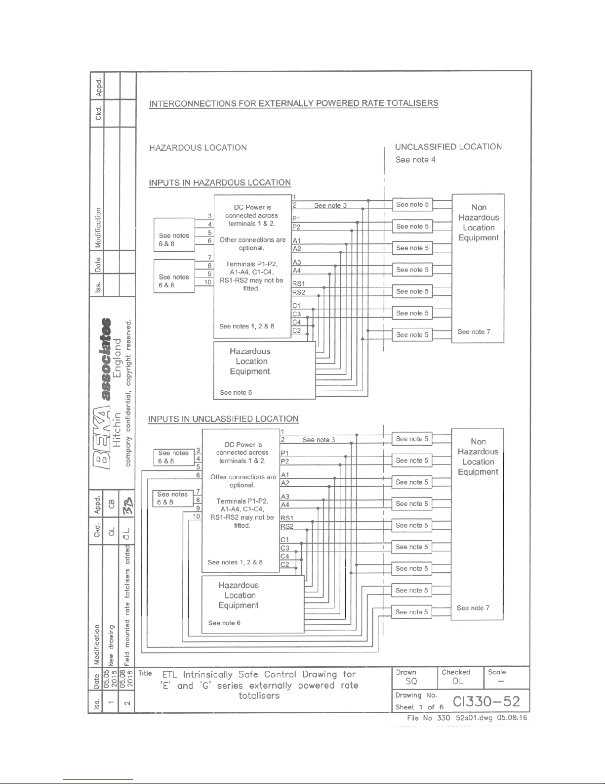
45
Page 46
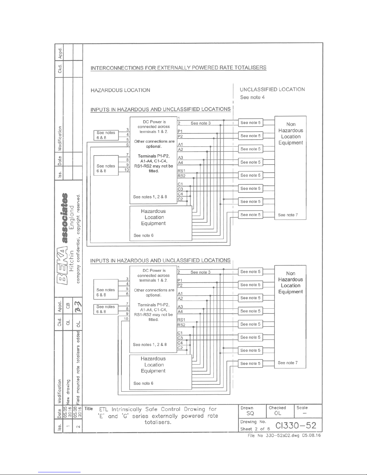
46
Page 47
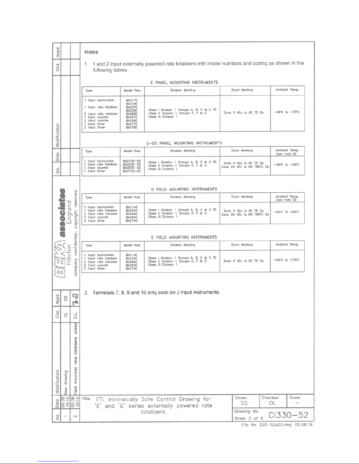
47
Page 48
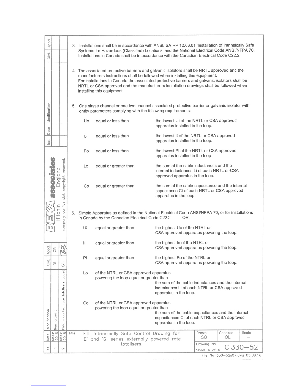
48
Page 49
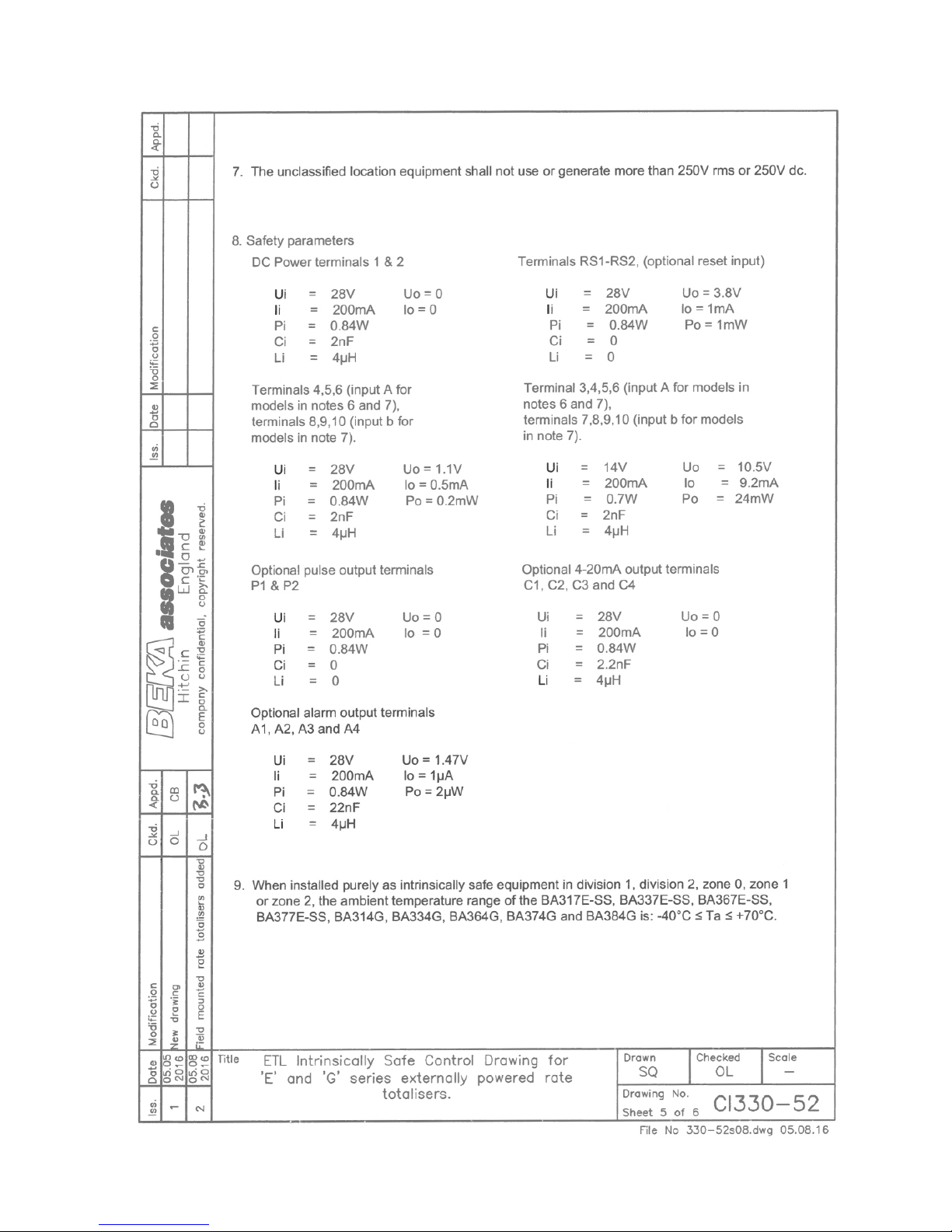
49
Page 50
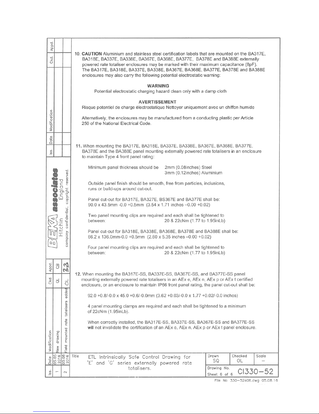
50
Page 51
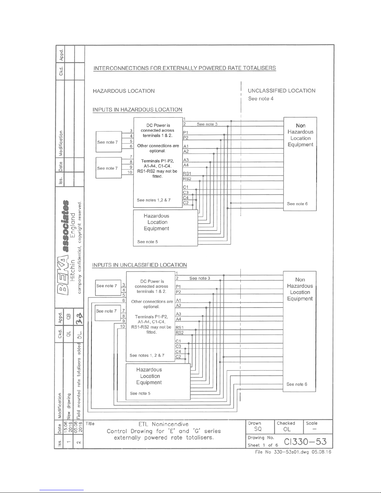
51
Page 52
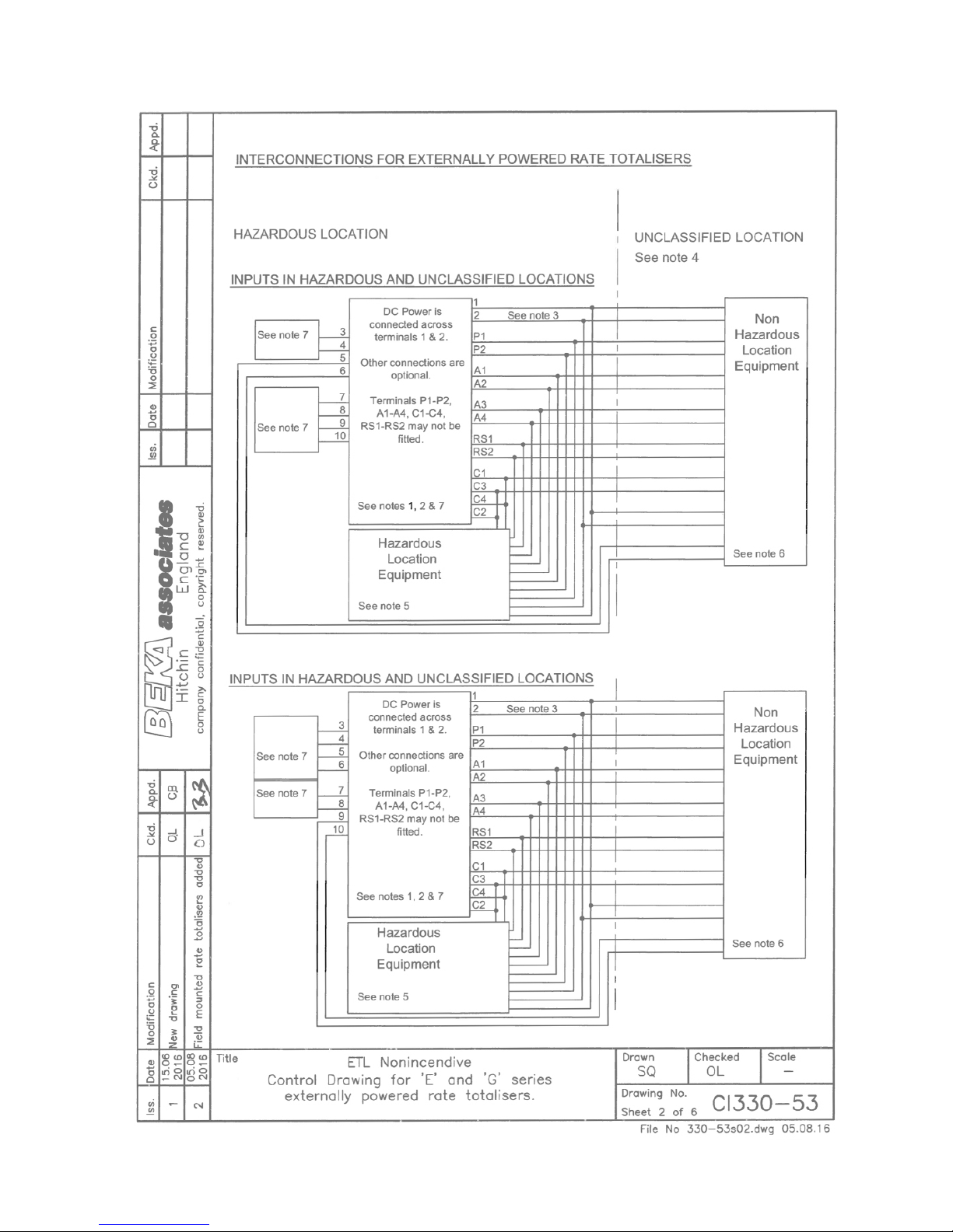
52
Page 53
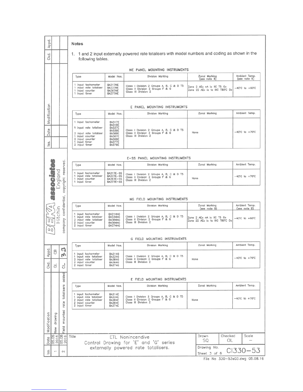
53
Page 54
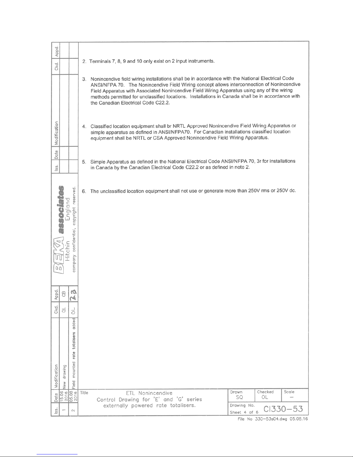
54
Page 55
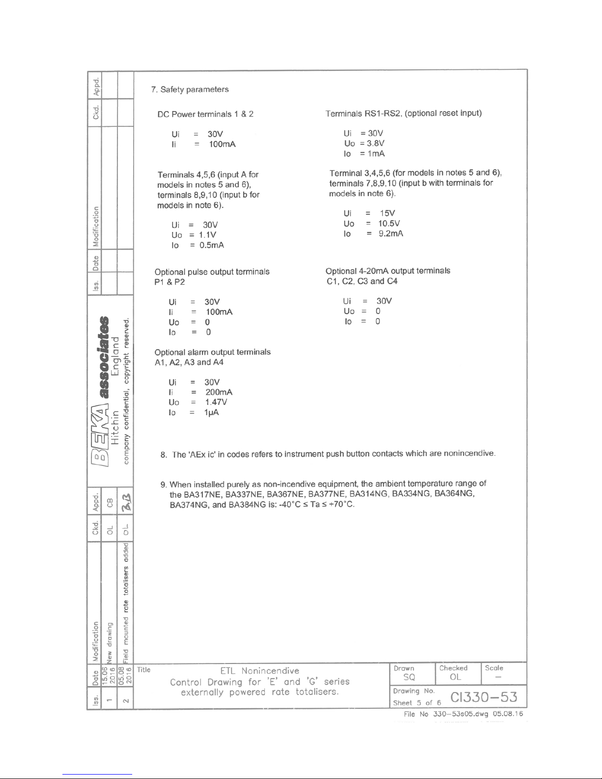
55
Page 56
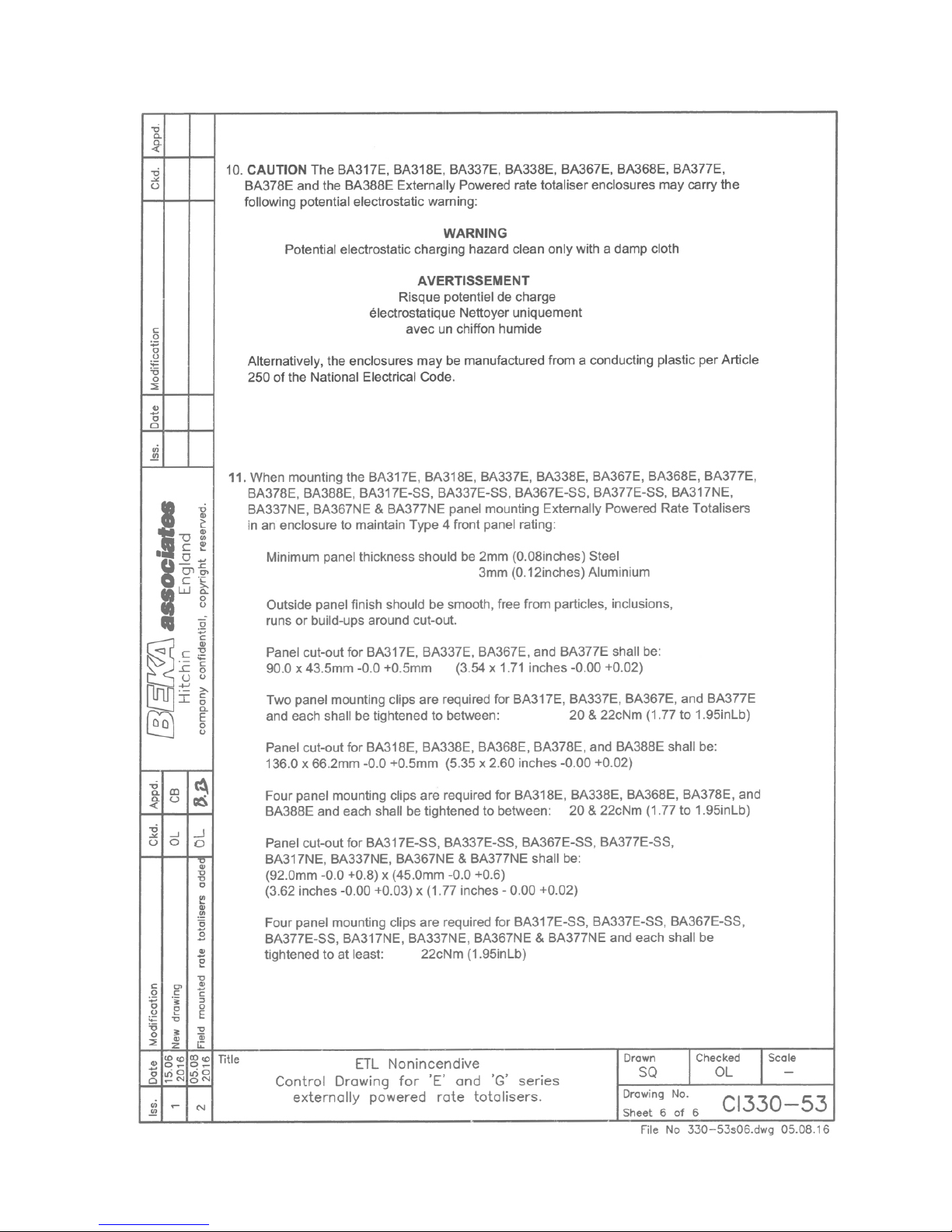
56
Page 57

APPENDIX 4
BA314E Tachometer
The BA314E Tachometer is functionally identical to
the BA314G Tachometer described in the main
sections of this manual, but differs in mechanical
construction, certification and factory fitted options.
All BA314E Tachometers are fitted with:
A Green internally powered display backlight
Dual galvanically isolated alarms
An isolated 4/20mA current sink output
These are only available as factory fitted options for
the BA314G Tachometer.
A4.1 Mechanical construction
The BA314E is housed in a robust GRP IP66
enclosure with a separate terminal compartment.
Section A4.5 of this appendix describes the enclosure
and installation procedure.
A4.2 Certification
The BA314E has the same ATEX, IECEx and ETL
intrinsic safety certification as the BA314G, but the
BA314E does not have ATEX and IECEx dust
certification.
The safety parameters and certification numbers
specified in this manual for the BA314G Tachometers
also apply to the BA314E Tachometer. Therefore all
of the systems described for the BA314G in the main
section of this manual may also be used for the
BA314E.
A4.3 Location
The BA314E Tachometer is housed in a robust IP66
glass reinforced polyester (GRP) enclosure
incorporating an armoured glass window and stainless
steel fittings. It is suitable for exterior mounting in
most industrial installations, including off-shore and
waste water treatment sites. The Tachometer should
be positioned where the display is not in continuous
direct sunlight.
The field terminals and the two mounting holes are
located in a separate compartment with a sealed
cover allowing the instrument to be installed without
exposing the display assembly.
The enclosure is fitted with a bonding plate to ensure
electrical continuity between the three conduit / cable
entries.
A4.4 BA314E Accessories
A4.4.1 Units measurement & instrument
identification.
The BA314E is fitted with a blank escutcheon
around the liquid crystal display. This can be
supplied printed with any units of measurement and
tag information specified at the time of ordering.
Alternatively, the information may be added on-site
via an embossed strip, dry transfer or a permanent
marker.
To gain access to the escutcheon remove the
terminal cover by unscrewing the two 'A' screws
which will reveal two concealed 'D' screws.
Remove the push buttons by unscrewing the two 'C'
screws and un-plug the five way connector. Finally,
unscrew all four 'D' screws and carefully lift off the
front of the instrument. The location of all the
screws is shown in Fig A4.1.
Add the required legend to the display escutcheon,
or stick a new pre-printed self-adhesive escutcheon,
which is available from BEKA associates, on top of
the existing escutcheon. Do not remove the original
escutcheon.
The BA314E can also be supplied with a blank or
custom laser engraved stainless steel plate secured
by two screws to the front of the instrument
enclosure. This plate can typically accommodate:
1 row of 9 alphanumeric characters 10mm high
or 1 row of 11 alphanumeric characters 7mm high
or 2 rows of 18 alphanumeric characters 5mm
high.
A4.4.2 Pipe mounting kits
The BA314E Tachometer is surface mounting, but
may be pipe mounted using the BA392D or the
BA393 pipe mounting kit.
57
Page 58
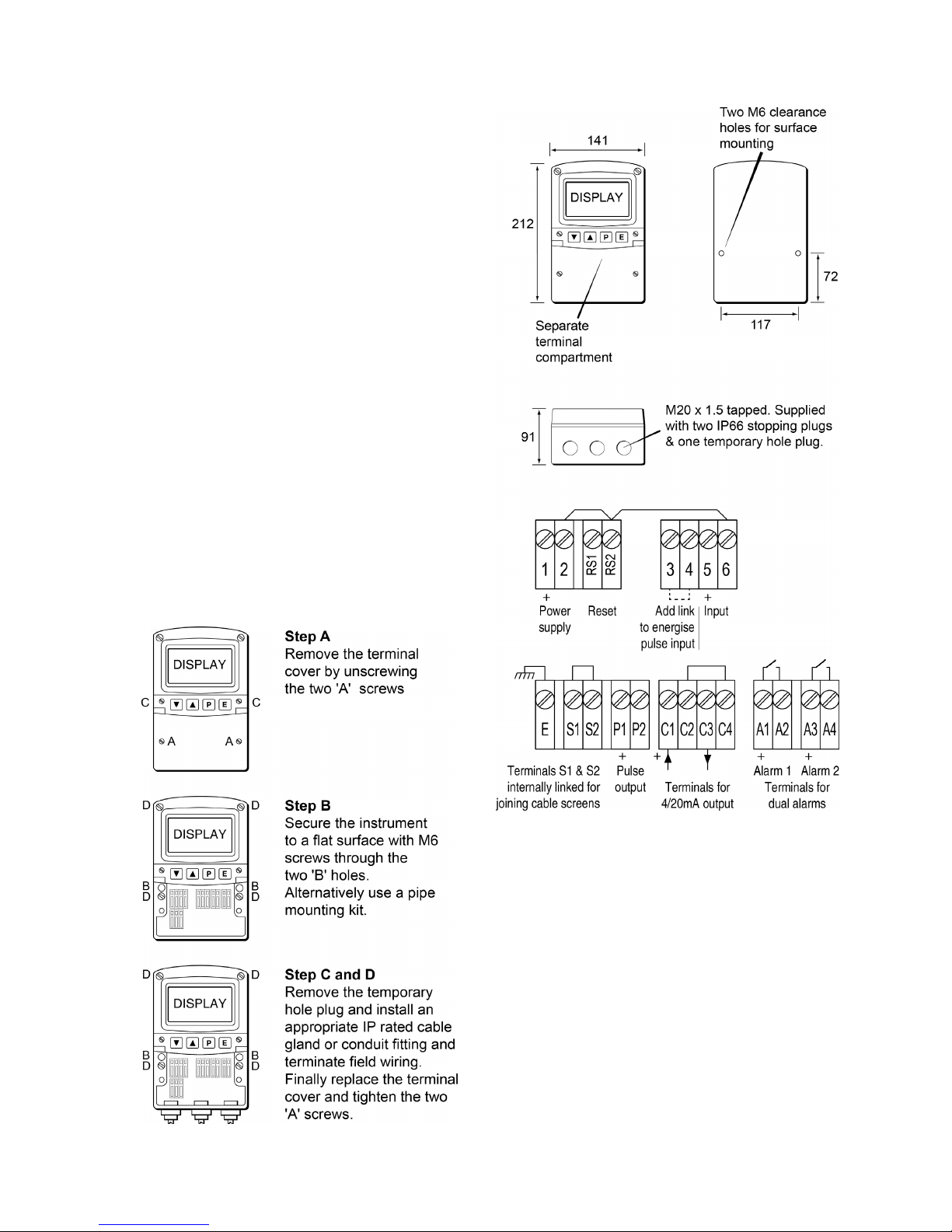
A4.5 Installation Procedure
Fig A4.1 illustrates the instrument installation
procedure.
a. Remove the instrument terminal cover by
unscrewing the two captive 'A' screws.
b. Mount the instrument on a flat surface and
secure with screws or bolts through the two 'B'
holes. Alternatively secure to a vertical or
horizontal pipe using a BA392D or BA393 pipe
mounting kit.
c. Remove the temporary hole plug and install an
appropriate IP rated cable gland or conduit
fitting. If more than one entry is required, one
or both of the IP66 stopping plugs may be
replaced with an appropriate IP rated cable
gland or conduit fitting.
d. Connect the field wiring to the terminals as
shown in Fig A4.2.
7 Replace the instrument terminal cover and
evenly tighten the two 'A' screws.
If the BA314E is not bolted to an earthed post or
structure, the earth terminal should be connected to
the plant potential equalising conductor.
Fig A4.1 BA314E installation procedure
Fig A4.2 Dimensions and terminal connections
A4.6 EMC
The BA314E compies with the requirements of the
European EMC Directive 2014/30/EU. For specified
immunity all wiring should be in screened twisted
pairs, with the screens earthed in the safe area.
58
 Loading...