

Page 1

AA A
V
CONNECTION INSTRUCTIONS #1
Differential Line Driver
Encoder signals from 5 VDC to 24 VDC (must specify the voltage when ordering)
This is the preferred type of encoder output as it has the best noise immunity. Connect each encoder signal to its like USB Converter
input (A to A, A/ to A/, etc).
No Connection
No Connection
ENCODER
Typical Connections for Each Encoder
Z
Z/
B/
B
A/
A
Figure 1
Standard Connection to
Encoder USB Converter
/A/
BB
B/ B/
ZZ
Z/ Z/
+V
0V
Encoder Differential Line Driver Output
Encoder USB Converter
▼
▼
▼
CONNECTION INSTRUCTIONS #2
Single Ended Line Driver
Encoder signal from 5 VDC to 24 VDC (must specify the voltage when ordering)
Connect encoder output A to optical isolator module input channel A, B to B and Z to Z. Connect the A/, B/, and Z/ inputs of the USB
Converter to circuit common of the encoder supply. Single ended operation is limited to shorter cable runs and is more susceptible to
noise.
No Connection
No Connection
Connect A/, B/, Z/ to
Encoder Circuit
Common
ENCODER
Z
B
Figure 2
Connection Diagram
Single Ended Line
AA
B B
Z Z
Enco rterder USB Conve
A/
B/
Z/
+
0V
A
Typical Connections for Each Encoder
+
0
Encoder Single Ended Line Driver
+
0
Encoder
Supply
Page 2
CONNECTION INSTRUCTIONS #3
A
/
p
Open Collector with or without Internal Pull-up Resistors
Encoder NPN (sinking) outputs.
Connect encoder output A/ to optical isolator module input A/, B/ to B/ and Z/ to Z/. Connect the A, B, and Z
inputs of the optical isolator to the encoder positive supply. Specify the input logic to the module the same as
the encoder power supply voltage.
Z
Encoder Supply
ENCODER
B/
A/
Typical Connections for Each Encoder
Figure 3
Connection Diagram
or A/
B or B/
Z or Z
+V
0V
Encoder O
Encoder USB Converter
A
A/
B
B/
Z
Z/
+V
Encoder Supply
0V
en Collector Output
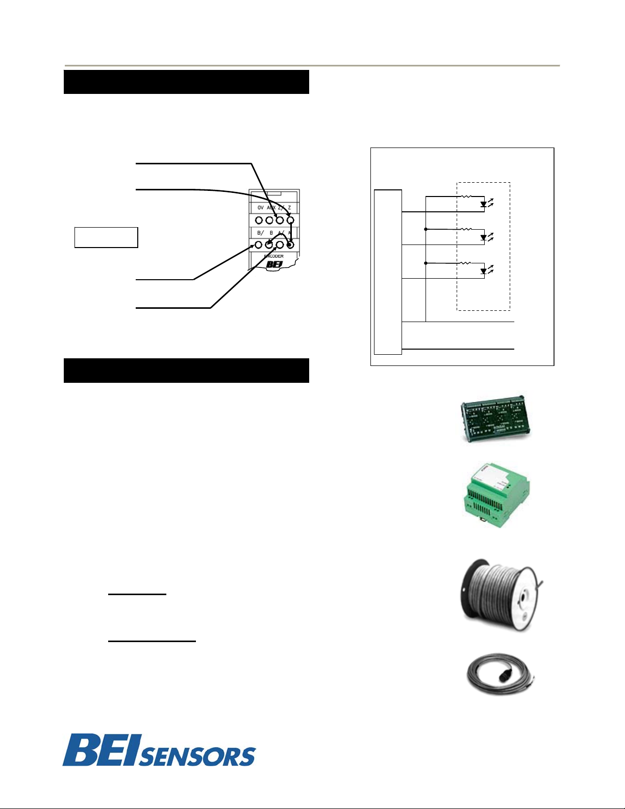
Additional Modules and Accessories
ENCODER SIGNAL BROADCASTER MODULE
Accepts standard incremental encoder inputs and can broadcast up to four
encoder signals to four independent devices. Each of the broadcast signals
are optically isolated eliminating ground loops.
POWER SUPPLY
With a wide range of acceptable input voltages (AC and DC) this DIN Rail
mountable power supply is usable in virtually all industrial applications
worldwide. It has built in surge protection to reduce faults due to transients and
it has 100% reserve capacity for startup and overload conditions.
CABLE AND CABLE ASSEMBLIES
Cable reels for your own custom wiring requirements or cable assemblies are
available, using high quality custom BEI standard cable consisting of four, low
capacitance shielded twisted pairs with an overall shield, extra large
conductors for power, and signal ground; all within an abrasion-resistant PVC
jacket.
Cable Reels
100 ft. reel Part No. 37048-003-100
500 ft. reel Part No. 37048-003-500
Cable Assemblies
Part Nos. for MS3106F14S-6S Mating Connector
10 ft. # 31186-1410 │ 20 ft. # 31186-1420 │30ft. # 31186-1430
Part Nos. for MS3106F16S-1S Mating Connector
10 ft. # 31186-1610 │ 20 ft. # 31186-1620 │30ft. # 31186-1630
Part Nos. for MS3106F18S-1S Mating Connector
10 ft. # 31186-1810 │ 20 ft. # 31186-1820 │30ft. # 31186-1830
Page 3

MODULE PINOUT
Absolute Encoder Connections
PIN Description Notes
D Data Data Line From encoder
D/ Data/ Data/ Line From Encoder
C Clock Clock Line From Encoder
C/ Clock/ Clock/ Line From Encoder
V+ +V
0V
*Not internally connected in Module
0V (Circuit
common)
+V from external
power supply*
Connect 0V from external
power supply
MODULE USB COMMANDS
Incremental Encoder Connections
PIN Description Notes
A Channel A Channel A Line From Encoder
A/ Channel A/ Channel A/ Line From Encoder
B Channel B Channel B Line From Encoder
B/ Channel B/ Channel B/ Line From Encoder
Z Channel Z Channel Z Line From Encoder
Z/ Channel Z/ Channel Z/ Line From Encoder
V+ V+
0V
0V(Circuit
Common)
+V from external
power supply*
0V from external
power supply*
ABSOLUTE ENCODER COMMANDS (see page 4)
Set Data Length of Encoder (8 to 32 bits)
Read Encoder Position
GENERAL COMMANDS
Read module Part Number and Serial Number
(see page 4)
INCREMENTAL ENCODER COMMANDS
Set Encoder Count Mode, Pulse/Dir, X1, X2, X4 and
Counter Width
Set Encoder Counter to Preset/Zero on Z Channel
Trigger
Set Encoder Counter to Value XXXX
Read Encoder Counter Value
Read Encoder Status Flags
(see page 3)
USB COMMUNICATION PROTOCOL
Download the appropriate driver package for your operating system from: http://www.beisensors.com
and install the USB to serial link drivers. When you plug in the module via the supplied USB cable, you
should notice an additional serial port becomes active on your PC (for example, COM3). You can check
which port it is by going into the device manager in windows (right-click MyComputer, select Properties, go
to Hardware/Device Manager, expand the Ports item.). You can now communicate with the device with any
serial communication program (such as HyperTerminal, which comes with Windows). The serial port
settings are 115200 baud, 8 data bits, no parity bit, 1 stop bit, no flow control.
The general formats of the commands are as follows: $<address><command><Encoder #><data><cr>
Commands that return data will respond according to their command description.
Successful commands that do not return data will respond with an ACK: *<address>ACK<cr>
Unsuccessful commands will respond with a NACK: *<address>NACK<cr>
The dollar sign ($) is the start of packet character. The <address> field is a one-character field, which
specifies the address of the module that the command is intended for (at this time, only address 0 (zero) is
supported). The <command> field specifies the command being sent. All commands contain an <Encoder
#> field. Valid encoder values are 1 or 2. The <data> field is any data required by the specific command
being sent, if any. The <cr> field is a carriage-return character (0Dh). For this document, commands are
designated as UPPER-CASE characters and data fields are designated in lower-case characters.
Page 4

INCREMENTAL ENCODER COMMAND SET
F - Read Encoder Status Flags
This command reads the three encoder status flags: Carry, Borrow and Power-up. The “c” field is the Encoder # (1 to 2). The Carry flag
is set whenever a carry rollover occurs (counter rolls from max value to zero) in the quadrature counter. Likewise, the Borrow flag is set
whenever a borrow occurs (counter rolls form zero to max value). The Power-up bit is set only upon initial power application to the unit.
This can be used to detect loss of power to the unit. Each flag will return a single character (either 0 or 1) representing the current state
of the flag. All three flags are reset to zero after the response is sent.
I - Set Encoder Index Configuration
This command sets the index configuration for each encoder channel. The “c” field is the Encoder # (1 to 2). The index can either be
enabled or disabled by sending a 1 or a 0 respectively for data field 'e'. If set to disabled, the <value> field is omitted. If enabled, the
<value> field is a number that the counter will be preset to when the index occurs. To zero the counter on index, set this value to 0. The
length of the <value> field will depend on the currently selected counter width (see Quadrature Configuration command 'Q'). For an 8,
16, 24 or 32 bit counter the <value> field will be 3, 5, 8 or 10 characters long respectively. Power on default configuration is index
disabled.
Q - Set Quadrature Configuration
This command sets the quadrature configuration for each encoder channel. The “c” field is the Encoder # (1 to 2). The "m" field sets the
count mode, which can be set to one of four values. A value of 0 is Pulse/Dir mode, where a count pulse is input on input A and count
direction is input on input B. Values 1, 2 and 3 are quadrature count modes X1, X2 and X4 respectively. The "w" field sets the counter
width. Either 8 bit, 16 bit, 24 bit or 32 bit widths can be selected by sending a value of 0, 1, 2 or 3 respectively. The “s” field sets the
counter style. A value of 0 is free running counter a value of 1 is moulo-n counter (n = current index value from I command). Power on
default configuration is quadrature X1, 24 bit, free running counter.
R - Read Encoder Count Value
This command reports back the current count value of the encoder channel. The “c” field is the Encoder # (0*, 1 to 2). The length of the
<value> field will depend on the currently selected counter width (see Quadrature Configuration command 'Q'). For an 8, 16, 24 or 32 bit
counter the <value> field will be 3, 5, 8 or 10 characters long respectively.
S - Set Encoder Counter Value
This command sets the encoder's counter to a specific value. The “c” field is the Encoder # (1 to 2). The length of the <value>
depend on th
<value> field will be 3, 5, 8 or 10 characters long respectively.
Send: $0Fc<cr>
Success: *0Fcxxx<cr>
Failure: *0NACK<cr>
Example: $0F1<cr>
Send: $0Ice<value><cr>
Success: *0ACK<cr>
Failure: *0NACK<cr>
Example: $0I2100123<cr>
Send: $0Qcmws<cr>
Success: *0ACK<cr>
Failure: *0NACK<cr>
Example: $0Q131<cr>
Send: $0Rc<cr>
Success: *0Rc<value><cr>
Failure: *0NACK<cr>
Example: $0R2<cr>
* If zero is sent as the encoder number, it will perform a read of both encoder channels. Each channel’s value will be sent
back in the data format specified by the encoder type (quadrature or SSI) with a comma between each data field. In the
following example, channels 1 and 2 are quadrature and set for 16 bit, with a count value of 12345 for each.
Example: $0R0<cr>
e currently selected counter w
Send: $0Sc<value><cr>
Success: *0ACK<cr>
Failure: *0NACK<cr>
Example: $0S1210<cr>
*0F1101
For channel 1, the Carry flag is set, Borrow is cleared, and Power-up is set.
Enables encoder channel 2 index, with a preset value of 00123 (setup for 16 bit counter width)
Sets channel 1 to quadrature X4 mode, 16 bit width.
*0R200004095<cr>
Reads the current count value of encoder channel 2, which is configured for 24 bits (8 character length).
The reported value is 00004095.
*0R012345,12345<cr>
field will
idth (see Quadrature Configuration command 'Q'). For an 8, 16, 24 or 32 bit counter the
Sets encoder channel 1 counter to a value of 210, which is configured for 8 bits (3 character length).
Page 5

ABSOLUTE ENCODER SSI COMMAND SET
L - Set SSI Data Read Length
This command sets the expected data length for each attached SSI encoder. Valid data length values are from 08 to 32 bits. “c” is the
Encoder # (1 to 2). “p” is the parity select, where a value of 0 = parity off and 1 = parity on. The power-up default value is 12 bit for
both encoders.
In this example, the data length for SSI encoder #1 is set to 16 bits, no parity
R - Read SSI Encoder Data
This command reads each SSI encoder’s current position value along with the encoder’s parity bit (optional). “c” is the
Encoder # (0*, 1 to 2). The length of the <value> field will depend on the currently selected read length (see 'L' command above). For
an 8, 16, 24 or 32 bit read length the <value> field will be 3, 5, 8 or 10 characters long respectively. The “,” is a
delimiting character and the “p” is the parity bit read from the encoder.
Send: $0Lcxxp<cr>
Success: *0ACK<cr>
Failure: *0NACK<cr>
Example: $0L1160<cr>
Send: $0Rc<cr>
Success: *0Rc<value>,p<cr>
Failure: *0NACK<cr>
Example: $0R2<cr>
*0R204095,0<cr>
In this example, a read command is sent to encoder #2. A decimal value of 4095 counts, the maximum
reading from a 12 bit encoder, is reported back with a parity bit of 0.
* If zero is sent as the encoder number, it will perform a read of both encoder channels. Each channel’s value will be sent
back in the data format specified by the encoder type (quadrature or SSI) with a comma between each data field. In the
following example channels 1 and 2 are SSI and set for 12 bit no parity, with a value of 4095 for both.
Example: $0R0<cr> *0R04095,04095<cr>
GENERAL COMMAND SET
V - Read Part Number and Serial Number
This command reads the part number and serial number of the encoder converter. The part number is 13 characters
long, while the serial number is 8 characters.
A – Automatic Data Sample Readings (Special feature)
This command starts the automatic reading of all encoder channels with an accurate timing between readings. Field
'xxxxx' is a five digit number that sets the number of milliseconds between readings (between 5 and 65535mS).
Send a '$' character to stop automatic reading mode. Allow at least 5mS after exiting auto mode before sending
another command.
Send: $0V<cr>
Success: *0Vppppppppppppp,ssssssss<cr>
Failure: *0NACK<cr>
Example: $0V<cr>
*0V924-60013-001,HH123456<cr>
In this example, the part number is 924-60013-001 and the serial number is HH123456.
Send: $0Axxxxx<cr>
Success: *0ACK<cr>
Failure: *0NACK<cr>
Example: $0A00100<cr>
*0ACK<cr>
*0R012345678,12345678<cr>
*0R012345678,12345678<cr> (100mS later)
*0R012345678,12345678<cr> (100mS later)
...
...
...
In this example, automatic data readings are enabled every 100mS (00100). The ACK is sent
back, followed by readings every 100mS until stopped.
These commodities, technology or software if exported from the United States must be in accordance with the Bureau of Industry and Security,
Export Administration Regulations. Diversion contrary to U.S. law is prohibited.
 Loading...