

Page 1
p
BEI Sensors SAS
Espace Européen de l’Entreprise
9, rue de Copenhague
MHM5
B.P. 70044 Schiltigheim
F 67013 Strasbourg Cedex
Tél : +33 (0)3 88 20 80 80
Fax : +33 (0)3 88 20 87 87
Mail : info@beisensors.com
www.beisensors.com
Web :
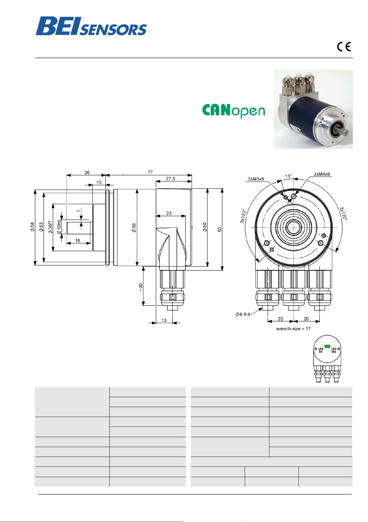
CANOPEN ABSOLUTE MULTI-TURN ENCODER, MHM510-CANO RANGE
MHM510-CANO, standard encoder Ø58mm with CANopen interface:
Robust and compact design
Solid shaft version Ø 10 mm (06 mm available upon request)
Precision ball bearings with sealing flange
High temperatures performances –40°C … +85°C
Code disc made of unbreakable and durable plastic
Mechanical memorisation of the number of turns by gears
Resolution : 13 bits = 8192 steps/turn (max 16 bits)
Number of turns : 12 bits = 4096 turns (max 14 bits)
Polarity inversion and short circuit protection
Highly integrated circuit in SMD-technology
MHM510-CANO (connection cap included)
Status indication with two LED’s in the connection ca
The LED behaviour was designed in accordance to the CiA normative DR 303-3 CANopen indicator
specification
MECHANICAL DATA
Cover : aluminum
Material
Stainless steel option
Body : aluminum
Shaft: stainless steel
Max. shaft loading
Axial : 40 N
Radial : 110 N
Shaft Inertia ≤ 30 g.cm²
Torque ≤ 3 N.cm
Vibrations (EN 60068-2-6) ≤ 10 g (10Hz… 1 000Hz)
Weight 600 g
Operating temperature - 40 … + 85°C
Storage temperature - 40 ... + 85°C
Humidity
Protection class (EN 60529)
98 % without condensation
IP 65: body
IP 64: shaft
RPM (continuous operation)) 6 000 rpm Lifetime in 108 revolutions with Fa / Fr (axial / radial)
Shock (EN 60068-2-27)) ≤ 100 g (halfsinus, 6 ms) 40 N / 60 N 40 N / 80 N 40 N / 110 N
Shock (EN 60028-2-29) ≤ 10 g (half-sinus, 16ms) 25 10 4
Changes possible without further notice - Version 100629
Page 2
BEI Sensors SAS
Espace Européen de l’Entreprise
9, rue de Copenhague
MHM5
B.P. 70044 Schiltigheim
F 67013 Strasbourg Cedex
Tél : +33 (0)3 88 20 80 80
Fax : +33 (0)3 88 20 87 87
Mail : info@beisensors.com
www.beisensors.com
Web :
CANOPEN ABSOLUTE MULTI-TURN ENCODER, MHM510-CANO RANGE
ELECTRICAL DATA
Interface ISO 11898 Power consumption max 2,5W
Transmission rate Max 1 MBauds Step Frequency LSB 800 kHz
Device addressing by rotary switches Accuracy + ½ LSB
Power supply 10 – 30Vdc EMC EN 61000-6-4 EN 61000-6-2
Current consumption max 100mA (24Vdc) Electrical lifetime > 105 h
TRANSMISSION MODES
POLLED Mode
CYCLIC Mode
SYNC Mode
PROGRAMMABLE PARAMETERS
Operating
Parameters
By a remote-transmission-request telegram the connected host calls for the current process value. The
absolute rotary encoder reads the current position value, calculates eventually set-parameters and sends
back the obtained process value by the same identifier
The absolute rotary encoder transmits cyclically - without being called by the host - the current process
value. The cycle time can be programmed in milliseconds for values between 1 ms and 65536 ms
After receiving a sync telegram by the host, the absolute rotary encoder answers with the current process
value. If more than one node number (encoder) shall answer after receiving a sync telegram, the answer
telegrams of the nodes will be received by the host in order of their node numbers. The programming of an
offset-time is not necessary. If a node should not answer after each sync telegram on the CAN network, the
parameter sync counter can be programmed to skip a certain number of sync telegrams before answering
again
This parameter determines the counting direction, in which the output code increases or decreases. As an
important operating parameter the code sequence (complement) can be programmed
Resolution per turn Value between 1 and 8192 can be programmed
Total resolution
‘’Max range’’
Preset Value
Limit Switch,
Min. and Max
This parameter is used to program the desired number of measuring units over the total measuring range.
This value may not exceed the total resolution of the absolute rotary encoder.
The preset value is the desired position value, which should be reached at a certain physical position of the
axis
Two position values can be programmed as limit switches. By reaching these values one bit of the 32 bit
process value is set to high level
Cam One free programmable cam can be set in the total measuring range
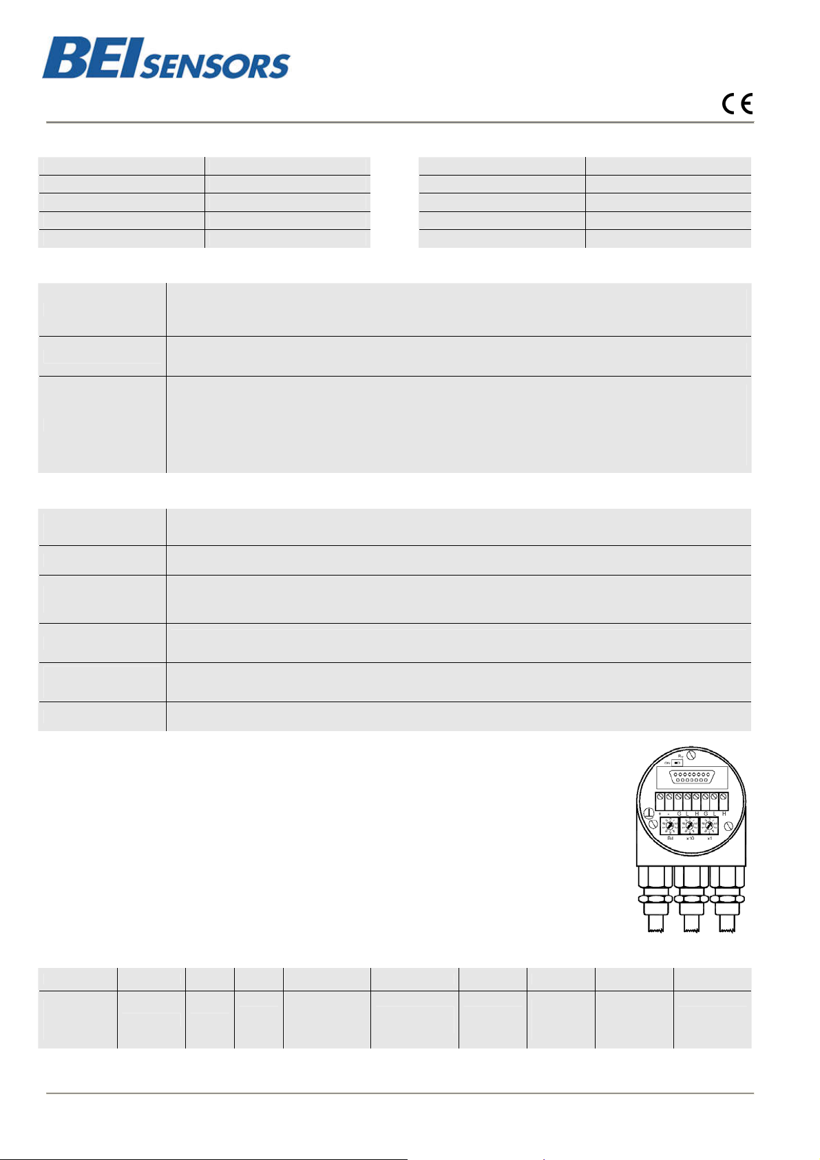
INSTALLATION
The rotary encoder is connected by two or three cables depending on whether the power supply is
integrated into the bus cable or connected separately. If the power supply is integrated into the bus
cable, one of the cable glands can be fitted
with a plug. The cable glands are suitable for cable diameters from 5.5 up to 9 mm
CONFIGURATION
The setting of the node number is achieved by 2 turn-switches in the connection cap. Possible
addresses lie between 0 and 89 whereby every address can only be used once. Inside the encoder
the defined address is increased by one. The connection cap can easily be opened for installation
by removing the two cap screws
A termination resistor is integrated in the connection cap. The resistor must be switched on if the
encoder is connected at the end or at the beginning of the bus
ORDERING REFERENCE
MHM5 CA A1 B 12 13 C 10 0 H3P
(Contact the factory for special versions ex:electronics, special flanges, connections…)
Absolute
multi turn
encoder
CANopen Version
Code :
Binary
Number of
turns
12
2
(4 096)
Resolution :
13
2
(8 192)
Clamp
flange
Shaft
diameter :
10mm
Without
mechanical
option
Connection
Cap
The ‘’H3P’’ terminal box version is shorter than the ‘’0CC’’ one.
Note:
Changes possible without further notice - Version 100629
 Loading...