

Page 1
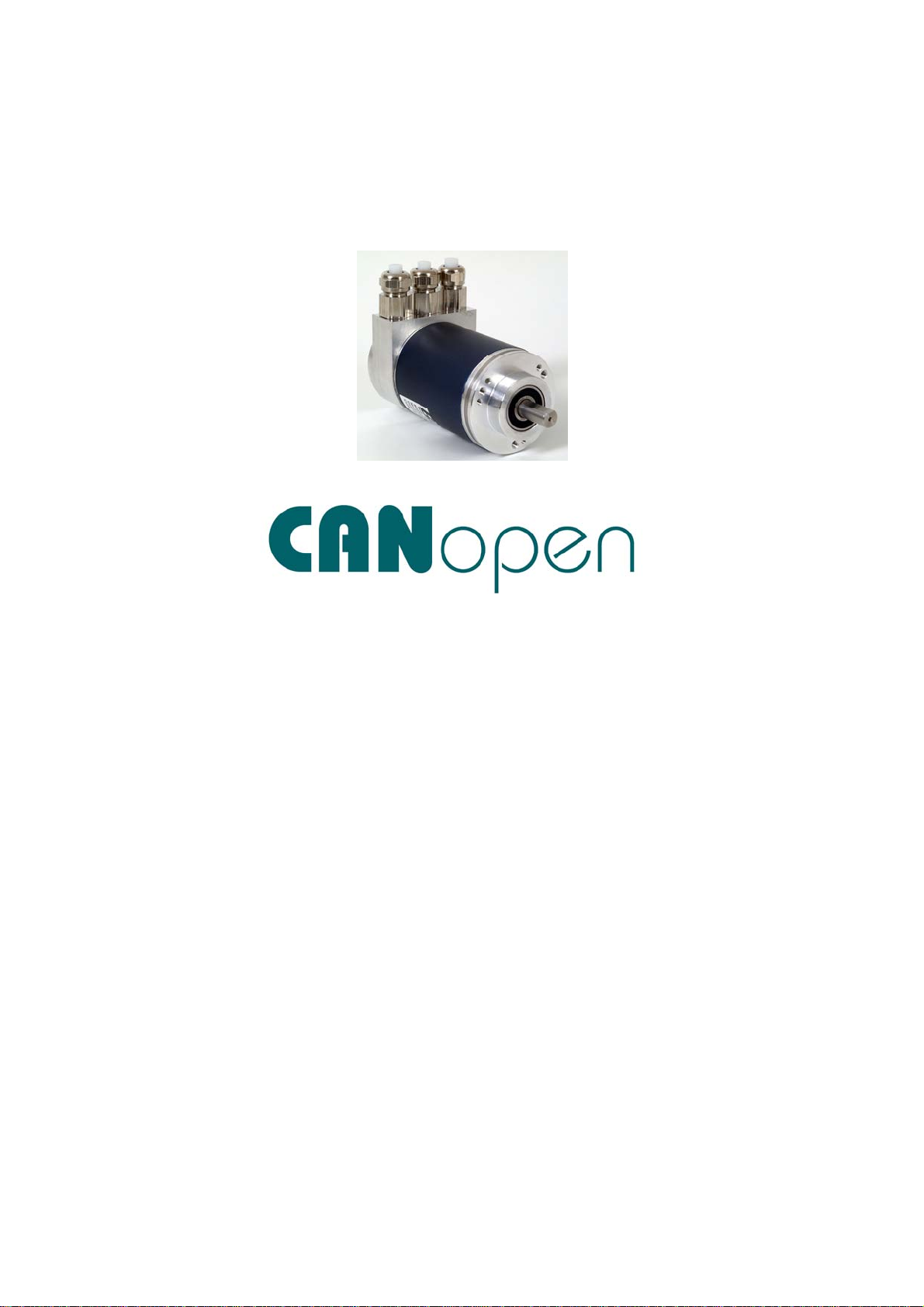
ABSOLUTE ROTARY ENCODER WITH CANOPEN INTERFACE
USER MANUAL
Main Features
- Compact and heavy-duty industrial design
- Interface: CANopen / CAN
- Housing: 58 mm
- Solid/hollow shaft: 6 or 10mm / 15mm
- Max. 65536 steps per revolution (16 Bit)
- Max. 16384 revolutions (14 Bit)
- Code: Binary
- Velocity and Acceleration Output
Mechanical Structure
- Aluminium flange and housing
- Stainless steel shaft
- Precision ball bearings with sealing or
cover rings
- Code disc made of unbreakable and
durable plastic
Programmable Parameters
- Direction of rotation (complement)
- Resolution per revolution
- Total resolution
- Preset value
- Two limit switches and eight cams
- Baud rate and CAN-identifier
- Transmission mode: Polled mode, cyclic
mode, sync mode
- Layer Setting Services
Electrical Features
- Temperature insensitive IR-opto-receiver
asic with integrated signal conditioning
- Connection cap: Status indication with
two LEDs
- Polarity inversion protection
- Over-voltage-peak protection
Version 07/10 BEI Sensors CANopen Manual serie M 1
Page 2

Table of Contents
General Security Advise......................................4
About this Manual................................................4
1. Introduction......................................................5
1.1 General CANopen Information.........................5
2. Installation........................................................7
2.1 Connection via Connection Cap.......................7
2.1.1 Signal Assignment ........................................7
2.1.2 Bus Termination in Connection Cap .............8
2.1.3 Setting Node Number in Connection Cap ..... 9
2.1.4 Setting Baudrate in Connection Cap...........10
2.1.5 Status of the connection cap LEDs ............. 10
2.2 Installation of Connector and Cable
encoders .............................................................. 12
2.2.1 Signal Assignment ......................................12
2.2.2 Setting Node Number .................................13
2.2.3 Setting Baud Rate.......................................13
2.2.4 Switching the integrated Bus Terminal
Resistor................................................................ 14
Object 3002h: Terminal Resistor..........................14
3. Technical Data................................................15
Electrical Data...................................................... 15
Mechanical Data .................................................. 15
Minimum Mechanical Lifetime.............................. 16
Environmental Conditions .................................... 16
4. Configuration .................................................17
4.1 Operating Modes ...........................................17
4.1.1 General ....................................................... 17
4.1.2 Mode: Preoperational.................................. 17
4.1.3 Mode: Start - Operational............................ 17
4.1.4 Mode: Stopped............................................ 18
4.1.2 Reinitialization of the Encoder..................... 18
4.2 Normal Operating........................................... 18
4.3 Storing Parameter..........................................19
4.3.1 List of storable Parameter ...........................19
4.3.1 Storing Procedure ....................................... 20
4.4 Restoring Parameters .................................... 20
4.5 Usage of Layer Setting Services (LSS).......... 20
5. Programmable Parameters ...........................22
5.1 Programming example: Preset Value ............23
5.1.1 Set Encoder Preset Value........................... 23
5.2 Communication Profile DS301 specific
objects from 1000h - 1FFFh ................................ 25
5.3 Manufacturer specific objects 2000h –
5FFFh.................................................................. 26
5.4 Application specific objects 6000h – 67FEh .. 26
5.5 Object Descriptions ....................................... 27
Object 1000h: Device Type ................................. 27
Object 1001h: Error Register ............................... 28
Object 1003h: Pre-Defined Error Field ................ 28
Object 1005h: COB-ID Sync................................ 28
Object 1008h: Manufacturer Device Name.......... 29
Object 1009h: Manufacturer Hardware Version... 29
Object 100Ah: Manufacturer Software Version.... 29
Object 100Ch: Guard Time.................................. 29
Object 100Dh: Life Time Factor........................... 30
Object 1010h: Store Parameters ......................... 30
Object 1011h: Restore Parameters ..................... 30
Object 1012h: COB-ID Time Stamp Object ......... 31
Object 1013h: High Resolution Time Stamp........ 31
Object 1014h: COB-ID Emergency Object .......... 31
Object 1016h: Consumer Heartbeat Time ........... 32
Object 1017h: Producer Heartbeat Time ............. 32
Object 1018h: Identity Object .............................. 32
Object 1020h: Verify configuration....................... 33
Object 1029h: Error behaviour............................. 33
Object 1800h:
1st-TPDO-Communication-Parameter.................. 33
Object 1801h: 2nd TPDO Communication
Parameter............................................................ 33
Object 1A00h: 1st TPDO Mapping Parameter...... 35
Object 1A01h: 2nd TPDO Mapping Parameter..... 35
Object 1F50h: Download Program Area.............. 35
Object 1F51h: Program Control........................... 36
Object 2000h: Position Value .............................. 36
Object 2100h: Operating Parameters .................. 36
Object 2101h: Resolution per Revolution ............ 37
Object 2102h: Total Resolution ........................... 37
Object 2103h: Preset Value................................. 38
Object 2104h: Limit Switch, min. ......................... 39
Object 2105h: Limit Switch, max. ........................ 39
Object 2160h: Customer storage......................... 40
Version 07/10 BEI Sensors CANopen Manual serie M 2
Page 3

Object 2200h: Cyclic Timer PDO ......................... 40
Object 2300h: Save Parameter with Reset .......... 40
Object 3000h: Node Number ...............................41
Object 3001h: Baudrate ....................................... 41
Object 3002h: Terminal Resistor..........................41
Object 3010h: Speed Control............................... 42
Object 3011h: Speed Value ................................. 42
Object 3020h: Acceleration Control .....................42
Object 3021h: Acceleration Value........................ 43
Object 3030h: C2-C5-Behavior............................43
Object 4000h: Bootloader Control........................ 43
Object 6000h: Operating parameters...................44
Object 6001h: Measuring units per revolution...... 45
Object 6002h: Total measuring range in
measuring units....................................................45
Object 6003h: Preset value.................................. 45
Object 6004h: Position value ...............................45
Object 6030h: Speed Value ................................. 46
Object 6040h: Acceleration Value........................ 47
Object 6200h: Cyclic timer ................................... 48
Object 6300h: Cam state register ........................48
Object 6301h: Cam enable register .....................48
Object 6302h: Cam polarity register..................... 48
Object 6400h: Area state register ........................51
Object 6401h: Work area low limit ....................... 52
Object 6402h: Work area high limit...................... 52
Object 6500h: Operating status ........................... 52
Object 6501h: Single-turn resolution ................... 53
Object 6502h: Number of distinguishable
revolutions ........................................................... 53
Object 6503h: Alarms .......................................... 53
Object 6504h: Supported alarms ......................... 54
Object 6505h: Warnings ...................................... 54
Object 6506h: Supported warnings ..................... 55
Object 6507h: Profile and software version ......... 55
Object 6508h: Operating time.............................. 55
Object 6509h: Offset value .................................. 56
Object 650Ah: Module identification .................... 56
Object 650Bh: Serial number............................... 56
6. Troubleshooting............................................ 57
7. Mechanical Drawings.................................... 58
Appendix A: Order Codes................................. 65
Appendix B: History and Compatibility........... 68
Appendix C: Glossary....................................... 73
Appendix D: List of tables................................76
Appendix E: List of figures...............................76
Appendix F: Document history ........................ 76
Version 07/10 BEI Sensors CANopen Manual serie M 3
Page 4

General Security Advise
Important Information
Read these instructions carefully, and look at the
equipment to become familiar with the device
before trying to install, operate, or maintain it.
The following special messages may appear
throughout this documentation or on the
equipment to warn of potential hazards or to call
attention to information that clarifies or simplifies
a procedure.
The addition of this symbol to a
Danger or Warning safety label
indicates that an electrical hazard
exists, which will result in personal injury if the
instructions are not followed.
This is the safety alert symbol. It is
used to alert you to potential
personal injury hazards. Obey all
safety messages that follow this symbol to avoid
possible injury or death.
Please Note
Electrical equipment should be serviced only by
qualified personnel. No responsibility is assumed
by BEI Sensors for any consequences arising
out of the use of this material. This document is
not intended as an instruction manual for
untrained persons.
About this Manual
Background
This user manual describes how to install and
configure an absolute rotary encoder with
CANopen interface.
Relate Note
Version date: 14. July 2010
Version number: 1.1
Reference number: MBL20100714
Copyright
The company BEI Sensors claims copyright on
this documentation. It is not allowed to modify, to
extend, to hand over to a third party and to copy
this documentation without written approval by
the company BEI Sensors. Nor is any liability
assumed for damages resulting from the use of
the information contained herein. Further, this
publication and features described herein are
subject to change without notice.
User Annotation
BEI Sensors welcomes all reader to send us
feedback and commands about this document.
Version 07/10 BEI Sensors CANopen Manual serie M 4
Page 5

1. Introduction
This manual explains how to install and
configure the OPTOCODE II absolute rotary
encoder with CANopen interface applicable for
military and industrial applications with CANopen
interface. The product is fully compliant with CiA-
standards:
DS301V402 CANopen Application Layer
DR303-1 Cabeling and connector pin assignment
DR303-3 CANopen indicator specification
DS305V200 CANopen Layer Setting Service
DS306V1R3 Electronic datasheet specification
DS406V32 Device Profile for Encoders
Measuring System
The measuring system consists of a light source,
a code disc pivoted in a precision ball bearing
and an opto-electronic scanning device. A LED
is used as a light source which shines through
the code disc and onto the screen behind. The
tracks on the code disk are evaluated by an
opto-array behind the reticle. With every position
another combination of slashes in the reticle is
covered by the dark spots on the code disk and
the light beam on the photo transistor is
interrupted. That way the code on the disc is
transformed into electronic signals. Fluctuations
in the intensity of the light source are measured
by an additional photo transistor and another
electronic circuit compensates for these. After
amplification and conversion the electronic
signals are available for evaluation.
Single-Turn
Single turn encoders specify the absolute
position for one turn of the shaft i.e. for 360°.
After one turn the measuring range is completed
and starts again from the beginning.
Multi-Turn
Linear systems normally need more than one
turn of a shaft. A single turn encoder is
unsuitable for this type of application because of
the additional requirement of the number of
turns. The principle is relatively simple: Several
single turn encoders are connected using a
reduction gear. The first stage supplies the
resolution per turn, the stages behind supply the
number of turns.
There are several types of encoder versions.
Please refer to the datasheets to find out which
is the best version for your application.
1.1 General CANopen Information
he CANopen system is used in industrial
T
applications. It is a multiple access system
(maximum: 127 participants), which means that
all devices can access the bus. In simple terms,
each user checks whether the bus is free, and if
it is the user can send messages. If two users try
to access the bus at the same time, the user
with the higher priority level (lowest ID number)
has permission to send its message.
Users with the lowest priority level must cancel
their data transfer and wait before re-trying to
send their message. Data communication is
carried out via messages. These messages
consist of 1 COB-ID followed by a maximum of 8
bytes of data. The COB-ID, which determines
the priority of the message, consists of a
function code and a node number. The node
number corresponds to the network address of
Version 07/10 BEI Sensors CANopen Manual serie M 5
Page 6

the device. It is unique on a bus. The function
code varies according to the type of message
being sent:
Management messages (LMT, NMT)
Messaging and service (SDOs)
Data exchange (PDOs)
Layer Setting Services (LSS)
Predefined messages (synchronization,
emergency messages)
The absolute rotary encoder supports the
following operating modes:
Polled mode: The position value is only
given on request.
Cyclic mode: The position value is sent
cyclically (regular, adjustable interval)
on the bus.
SYNC mode: The position value is sent
after a synchronization message
(SYNC) is received. The position value
is sent every n SYNCs (n ≥ 1).
Other functions (offset values, resolution, etc)
can be configured. The absolute rotary encoder
corresponds to the class 2 encoder profile (DS
406 in which the characteristics of encoder with
CANopen interface are defined). The node
number and speed in bauds are determined via
rotary switches.
The transmission speed can range from
20kBaud up to 1Mbaud 1Mbaud (30m cable for
a maximum speed of 1Mbaud, 1000 m cable for
a maximum speed of 10 kbaud). Various
software tools for configuration and parameter-
setting are available from different suppliers. It is
easy to align and program the rotary encoders
using the EDS (electronic data sheet)
configuration file provided.
Further CAN-information is available at:
CAN in Automation (CiA) - International Users
and Manufacturers Group e.V.
Kontumazgarten 3
DE-90429 Nuremberg
www.can-cia.org/
(*) Reference: CAN Application Layer for
Industrial Applications
CiA DS201..207 V1.1 CAL-based
Communication Profile for Industrial
Systems
CiA DS301 CANopen Application Layer
CiA DS406 Device Profile for Encoders
We do not assume responsibility for
technical inaccuracies or omissions.
Specifications are subject to change without
notice.
Version 07/10 BEI Sensors CANopen Manual serie M 6
 Loading...