

Page 1
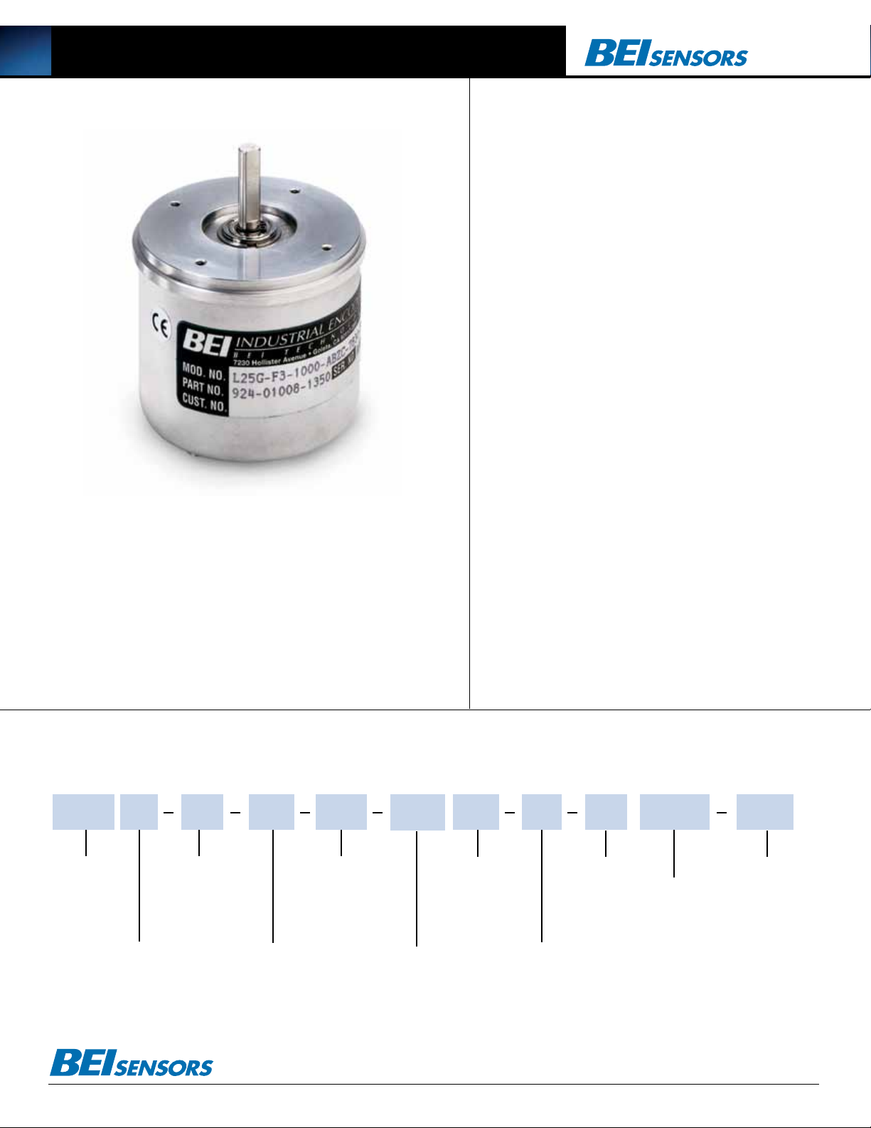
L25 Incremental Optical Encoder
Mechanical Specifications
Shaft Diameter: 1/4” nominal
Flat On Shaft: 0.80 long x 0.03 deep
Shaft Loading: up to 5 lbs. axial and 8 lbs. radial
Shaft Runout: .0005 T.I.R. maximum
Starting Torque at 25°C: 0.07 in-oz typical, 0.12 in-oz maximum without sealed
bearings; 0.50 in-oz typical, 1.0 in-oz maximum with sealed bearings
Bearings: Class ABEC 5
Shaft material: 416 stainless steel
Bearing Housing: Die cast aluminum with iridite finish
Cover: Drawn aluminum, 0.060” wall, protective finish standard. Die cast aluminum
with protective finish for EM, SM, ECS and SCS terminations
Bearing Life: 1 X 10⁹ revs (6,700 hrs at 2500 RPM)
Maximum RPM: 10,000
Moment of Inertia: 4.1 x 10⁻⁴ oz-in-sec
Weight: 13 oz. typical
Electrical Specifications
Code: Incremental
Cycles Per Shaft Turn: 1 to 28,800
Voltage/Output: (see note 5)
15V/V: Line Driver, 5–15 VDC in, V
28V/V: Line Driver, 5–28 VDC in, V
28V/5V: Line Driver, 5–28 VDC in, V
28V/OC: Open collector, 5–28 VDC in, OC
Current Requirements: TTL: 175 mA maximum 125 mA typical
Output Format: 2 channels in quadrature = 27º electrical typical. Optional index
is typically gated 1/2 cycle wide (see figure 1)
The L25 is a lighter duty version of BEI’s H25 optical encoder.
Incorporating the same high quality optics and electronics as the H25,
Protection Level: Reverse, overvoltage and output short circuit (4469, 7272 only)
Frequency Response: 100 kHz (see note 7), up to 800 KHz with interpolation option
Output Terminations: (see table 1)
out
out
out
2
= V
in
= V
in
= 5 VDC
out
the L25 also offers low starting torque. Other features include ABEC
5 bearings, EMI shielding, a 1/4” diameter stainless steel shaft and
a drawn aluminum cover. Typical applications include use with light
machine tools, test and laboratory instrumentation, the biomedical
industry and flow metering.
Environmental Specifications
Enclosure Rating: NEMA 2 (IP43)
Temperature: Operating, 0º to 70º C; extended temperature testing available
(see note 8); storage; -25º to 90º C
Shock: 50 g’s for 11 msec duration
Vibration: 5 to 2000 Hz @ 20 G’s
Humidity: 98% RH without condensation
NOTES & TABLES: All notes and tables referred to in the text can be found on the
back of this page.
Model L25 Ordering Options FOR ASSISTANCE CALL 800-350-2727
Use this diagram, working from left to right to construct your model number (Example: L25G-F3-SB-2000-ABZC-28V/V-SC18).
L25 G
TYPE:
L = Heavy Duty
25 = 2.500” Dia.
HOUSING CONFIG. LETTER:
G=2.62 Dia. Servo Mount
See dimensions
These commodities, technology or software if exported from the United States must be in accordance with the Bureau of Industry, and Security, Export Administration regulations. Diversion contrary to U.S law is prohibited.
OPTIONAL FACE
MOUNTS
F1, F2, F3, or F4
Blank = None
SHAFT SEAL CONFIGURATION:
SB = Seal Integral
with Bearing
Blank = Shielded Bearing
Tel: 805-968-0782 /800-350-2727 | Fax: 805-968-3154 / 800-960-2726
7230 Hollister Ave., Goleta, CA 93117-2807 | www.beisensors.com
CYCLES PER TURN:
(Enter Cycles)
See table 2
NO. OF CHANNELS:
A = Single Channel
AB = Dual Quad. Ch.
ABZ = Dual with Index
AZ = Single with Index
See note 3
COMPLEMENTS
C = Complementary
Outputs
Blank = None
See note 4
VOLTAGE/OUTPUT:
15V/V = 5-15 V
28V/5 = 5-28V
28V/OC = 5-28V
= 5-28V
See note 5
OUTPUT
TERMINATION
LOCATION:
E = End
S = Side
28V/V
in/out
in/out
5V
/
in
out
OC
/
in
out
MS3102R16S-1P
C = Pigtail Cable
CS = Cable with Seal
specified in inches
(i.e. C18 = Pigtail
See table 1 & note 9
OUTPUT
TERMINATION:
M16 =
D15 = DA15P
Cable length
18” long)
Specification No. 02004-001 Rev.08-11
SPECIAL
FEATURES:
S= Special
features specified
on purchase order
(consult factory)
See table 6
Page 2

L25 Incremental Optical Encoder
.125
.125
SC = 1.60
EC = 2.06
Ø 2.625
30°
45°
30°
2.06
0.20
DA15P
CONNECTOR
10-32 UNF-2B
0.188 Min. Deep
3 places equally spaced
on a Ø 1.875. bolt circle.
F1
4-40 UNC-2B
0.250 Min. Deep
4 places equally spaced
on a Ø 1.272 bolt circle.
(0.900 square, Ref.)
F2
4-40 UNC-2B
0.250 Min. Deep
4 places equally spaced
on a Ø 2.00 bolt circle.
F3
6-32 UNC-2B
F4
SIDE
CABLE (SC)
18" PIGTAIL
LEADS
STANDARD
(22AWG)
END
CABLE
(EC)
OPTIONAL
0.88
± 0.03
0.22
2.500
2.498
Ø
0.2497
0.2495
Ø
30°
45°
10-32 UNF-2B
0.188 Min. Deep
3 places equally spaced
on a Ø 1.875. bolt circle.
F1
4-40 UNC-2B
F2
0.22
30°
45°
10-32 UNF-2B
0.188 Min. Deep
3 places equally spaced
on a Ø 1.875. bolt circle.
F1
4-40 UNC-2B
0.250 Min. Deep
F2
30°
10-32 UNF-2B
0.188 Min. Deep
3 places equally spaced
on a Ø 1.875. bolt circle.
F1
30°
45°
10-32 UNF-2B
0.188 Min. Deep
3 places equally spaced
on a Ø 1.875. bolt circle.
F1
4-40 UNC-2B
0.250 Min. Deep
4 places equally spaced
on a Ø 1.272 bolt circle.
(0.900 square, Ref.)
F2
30°
45°
10-32 UNF-2B
0.188 Min. Deep
3 places equally spaced
on a Ø 1.875. bolt circle.
F1
4-40 UNC-2B
0.250 Min. Deep
4 places equally spaced
on a Ø 1.272 bolt circle.
(0.900 square, Ref.)
F2
4-40 UNC-2B
0.250 Min. Deep
4 places equally spaced
on a Ø 2.00 bolt circle.
F3
Notes and Tables
The connector style will determine pinouts. For example, an encoder with
ABC channels and an M18 connector uses the table to the right.
Table 1: Incremental Output Terminations
M14 CONNECTOR M16 CONNECTOR CHANNELS DESIGNATED IN MODEL NO.
PIN PIN ABZ ABC
EA AA
DB BB
CC ZA
BD +V (SUPPLY VOLTA GE)
FE —B
AF 0 V (CIRCUIT COMMON)
G CASE GROUND (CG) (except H20)
M18 CONNECTOR
PIN CHANNEL
AA
BB
CZ
D+V
E—
F0V
GCG
HA
IB
JZ
WIRE COLOR DA 15P CHANNELS DESIGNATED IN MODEL NO.
(22AWG) CONNECTOR
ABZ ABC ABZC
YEL 13 AAA
BLUE 14 BB B
ORN 15 Z— Z
W-Yel10— AA
W-Blu 11 —B B
W-Orn 12 —— Z
RED 6 +V (SUPPLY VOLTAGE)
BLK 10 V (CIRCUIT COMMON)
GRN 9 CASE GROUND (CG) (except H20)
WHITE SHIELD DRAIN (Shielded Cable Only)
M12 CONNECTOR
PIN CHANNEL
AA
BB
CZ
D+V
E—
F0V
GCG
HA
JB
KZ
Dimensions Figure 1
L25G - M16 or M18
SC = 1.60
EC = 2.06
SIDE
CABLE (SC)
18" PIGTAIL
LEADS
STANDARD
(22AWG)
END
CABLE
(EC)
OPTIONAL
Optional Face Mounts
30°
F1
10-32 UNF-2B
0.188 Min. Deep
3 places equally spaced
on a Ø 1.875. bolt circle.
.125
0.88
± 0.03
.125
2.500
Ø
2.498
0.2497
Ø
0.2495
45°
F2
4-40 UNC-2B
0.250 Min. Deep
4 places equally spaced
on a Ø 1.272 bolt circle.
(0.900 square, Ref.)
Ø 2.625
F3
4-40 UNC-2B
0.250 Min. Deep
4 places equally spaced
on a Ø 2.00 bolt circle.
Tables
Table 1–Incremental Output Terminations
The connector style will determine pinouts. For example, an encoder with ABC
channels and an M18 connector uses the table to the right.
Table 2–Disc Resolutions for Incremental Encoder Model L25
1, 2, 3, 5, 6, 7, 8, 10, 13, 16, 20, 24, 25, 26, 30, 32, 33, 34, 36, 37, 40, 45, 48, 50, 51, 56*, 60, 64, 66, 72, 75,
80, 86, 88, 90, 100, 102, 120, 122,125, 127, 128, 132, 144, 148, 150, 158, 160, 175, 176, 180, 187, 192, 200,
202, 204*, 217, 220, 240, 250, 254, 255, 256, 264*, 274, 280, 283, 288, 292, 300, 312, 320, 321, 325, 360,
366, 372, 375, 377, 380, 381, 384, 385, 393, 400, 430, 432, 450, 462, 480, 490, 500, 502, 508, 512, 522,
530, 550, 560*, 576, 598, 600, 604, 625, 628, 635, 638, 640, 660, 672, 676, 680, 687, 690, 700, 720, 725,
735, 740, 744, 748, 750, 762, 768, 780, 785, 800, 812, 825, 850, 864, 878, 888, 900, 912, 914, 938, 942,
955, 960, 1000, 1016, 1024, 1030, 1035, 1036, 1040, 1054, 1056, 1074, 1076, 1080,1088, 1100, 1101, 1125,
1136, 1200, 1237, 1250, 1257, 1270, 1280, 1300, 1314, 1332, 1333, 1390, 1400, 1414, 1427, 1440, 1484,
1500, 1562, 1570, 1596, 1600, 1650, 1666, 1718, 1745, 1774, 1800, 1840*, 1850, 1855, 1875, 1894, 1920,
1952, 1968, 1979, 1995, 2000, 2048, 2080, 2094, 2100, 2160, 2164, 2199, 2200, 2250, 2356, 2400, 2485,
2500, 2514, 2519, 2540, 3000, 3125, 3600, 4000, 4096, 5000
* AB or ABC output only. Note: Resolutions up to 72,000 are available.
Tel: 805-968-0782 /800-350-2727 | Fax: 805-968-3154 / 800-960-2726
7230 Hollister Ave., Goleta, CA 93117-2807 | www.beisensors.com
0.22
CONNECTOR
POSITION
1.30 (SM16)
1.65 (SM18)
MS3102R16S-1P
OR
MS3102R18-1P
CONNECTOR
CONNECTOR
SM
EM
POSITION
2.50
30°
F4
6-32 UNC-2B
0.250 Min. Deep
3 places equally spaced
on a Ø 2.00 bolt circle.
Output Waveform
1 CYCLE
90 Deg.
A
B
Z
A
B
Z
CCW Rotation Viewing Face
HI
LO
Notes
1. Mounting is usually done either using the D-style square flange mount, E- or G-style
servo mounts, or one of the standard face mounts, F1 for example. Consult factory for
additional face mount options.
2.The shaft seal is recommended in virtually all installations. The most common
exceptions are applications requiring a very low starting torque or those requiring
operation at both high temperature and high speed.
3. Non-standard index widths and multiple indices are available by special order.
Consult factory.
4. Complementary outputs are recommended for use with line driver type (source/
sink) outputs. When used with differential receivers, this combination provides a
high degree of noise immunity.
5. Output IC’s: Output IC’s are available as either Line Driver (LD) or NPN Open
Collector (OC) types. Open Collectors require pull-up resistors, resulting in higher
output source impedance (sink impedance is similar to that of line drivers). In
general, use of a Line Driver style output is recommended. Line Drivers source or
sink current and their lower impedance mean better noise immunity and faster
switching times. Warning: Do not connect any line driver outputs directly to
circuit common/OV, which may damage the driver. Unused outputs should be
isolated and left floating. Our applications specialists would be pleased to discuss
your system requirements and the compatibility of your receiving electronics with
Line Driver type outputs.
28V/V: Multi-voltage Line Driver (7272*): 100 mA source/sink. Input voltage 5 to
28 VDC +/- 5% standard (Note: V
used with 5 volt supply. Supply lines are protected against overvoltage to 60 volts
and reverse voltage. Outputs are short circuit protected for one minute. Supply
current is 120 mA typical (plus load current). This is the recommended replacement for 3904R and 7406R open collector outputs with internal pullup resistors.
It is also a direct replacement for any 4469, 88C30, 8830 or 26LS31 line driver
28V/5: Multi-voltage Line Driver (7272*): 100 mA source/sink. Input voltage 5
to 28 VDC +/- 5% standard, internally regulated with 5V (TTL compatible) logic
out. Supply lines are protected against overvoltage to 60 volts and reverse voltage. Outputs are short circuit protected for one minute. Supply current is 90 mA
typical (plus load current). Note: Limit encoder load to 2.5W max at ambient.
Example at 12 VDC: 2.5W/(+12VDC minus +5VDC) = 357 mA total allowed
current. Consult factory for your specific requirements.
15V/V: Multi-voltage Line Driver (4469*): 100 mA source/sink. Input voltage
5 to 15 VDC +/- 5% standard (Note: V
with 5 volt supply. Supply lines are protected against overvoltage to 60 volts
and reverse voltage. Outputs are short circuit protected for one minute. Supply
current is 90 mA typical (plus load current). This is a direct replacement for the
4469 Line Driver. 28V/OC: NPN Open Collector (3904*, 7273*). Current sink of
80 mA max. Current sourced by external pull- up resistor. Output can be pulled
up to voltage other than supply voltage (30 V max). Input voltage 5 to 28 VDC
+
/- 5% standard. Supply current is 120 mA typical. This replaces prior IC’s with
designations of 3904, 7406, 3302, 681 and 689. 5V/OCR, 15V/OCR, 24V/
OCR: Open Collector (3904R*, 7406R*, 7273R*): Current sink of 70 mA max.
Includes internal pull-ups sized at approximately 100 ohms/volt. Max current
source is 10 mA. Supply current is 100 mA typical, 120 mA with internal pullups. The 5V/OCR, 15V/OCR and 24V/OCR are often replaced by the 28V/V
in system upgrades. 3904, 3904R, 4469, 5V/V, 5V/OC, 5V/OCR, 9V/OC:
Intrinsically safe line driver and open collector outputs. These drivers are specific to intrinsically safe encoders, and are installed per the appropriate control
drawings listed in Table 2.on this page.
6. Special –S at the end of the model number is used to define a variety of
non-standard features such as special shaft lengths, voltage options, or special
testing. Please consult the factory to discuss your special requirements.
7. Higher frequency response may be available. Please consult with the factory.
8. Extended temperature ratings are available in the following ranges:
-40 to 70°C, -40 to 85°C, –20 to 105°C and –40 to 105°C depending on the
particular model. Some models can operate down to
-55°C. Extended temperature ranges can affect other performance factors.
Consult with factory for more specific information.
9. Mating straight plug receptacles may be ordered from the factory:
For M12 use MS3116F12-10S, For M14 use MS3106F14S-6S
For M14/19 use MS3116J14-19S, For M16 use MS3106F16S-1S
For M18 use MS3106F18-1S, For M20 use MS3106F20-29S
= Vin). This driver is TTL compatible when
out
= Vin). TTL compatible when used
out
 Loading...