

Page 1
Rev 2-20-14
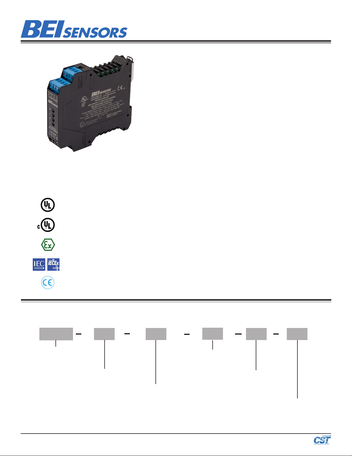
Intrinsic Safety Barrier
Specication No.: 02125-004
These c ommodities, te chnology or sof tware if expor ted from the Un ited States must b e in accordanc e
with the B ureau of Industr y, and Security, Ex port Adminis tration regul ations. Divers ion contrar y to U.S.
law is prohibited.
This Intrinsic Safety Barrier has certications
to be used as an associated apparatus for
intrinsically safe encoders installed in the
following hazardous locations:
US Class I, Group A,B,C,D;
Class II, Groups E,F,G; Class III
Canadian Class I, Zone 0, Group IIC
II 3 (1) G Ex nA [ia Ga] IIC T4 Gc
Ex nA [ia Ga] IIC T4 Gc
EN 55011 and 61000-6-2
This Intrinsic Safety Barrier Module is the perfect complement
to BEI’s Intrinsically Safe Encoders and, when used together,
constitutes a completely engineered solution for encoder
operation in Class I and Class II, Division 1 (Zone 0) Hazardous
Environments. This single barrier provides both power and
signal isolation for an incremental encoder with differential
quadrature outputs and an index. This all-in-one approach
saves the cost, inconvenience and system design time needed
when using separate power and signal barriers. This barrier
is galvanically isolated which eliminates the added cost of
maintaining a high integrity earth ground. With differential line
driver outputs, this barrier can be used to carry signals reliably
up to 500 feet with a bandwidth of up to 250 kHz. It is designed
around a standard DIN Rail mounting (Type EN 50022, 35 mm
X 7.5 mm) for easy installation in standard enclosures. A length
of DIN rail is supplied with each module. The module simply
snaps directly to the DIN rail and is ready to use.
The Intrinsic Safety Barrier Module is certied to be installed in
Class I, Div. 2 (Zone 2) areas.
When properly connected, differential data signals have an
inherent immunity to noise since it is rejected as common
mode. However if a connection between the encoder and the
barrier is broken or improperly terminated it can act as an
antenna and still create a signal. An open wire detection (ISD)
option is available on BEI’s Intrinsically Safe Barriers (28V/V
and 28V/5 only). In the event that the data line is cut or not
properly connected the ISD option can detect a change in the
impedance of the connection and cause the output data on
both legs of the differential signal to go low. This creates an
erroneous logic state that can be used by the operator to halt or
modify a process.
Intrinsic Safety Barrier Ordering Options for assistance, call 800.350.2727
Use this diagram, working from left to right to construct your model number (example: EM-DR1-IS-5-RTB-28V/V)
EM DR1
TYPE:
EM = Electronic Module, DIN Rail
mount
DR1 = 114.5 mm x 99mm x
PACKAGE STYLE:
22.5 mm
IS= Intrinsically Safe
ISD = Intrinsically Safe with
Open Wire Detection (available
with 28V/V or 28V/5 supply
voltage/output)
IS RTB
5=5 VDC
FUNCTION
5
OUTPUT VOLTAGE TO
ENCODER
OUTPUT TERMINATION:
RTB =
RemoveTerminal
Block
VOLTAGE/OUTPUT:
28V/V = 12-28 VDC, Vout = Vin
28V/5 = 12-28 VDC, Vout = 5 volts
28V/OC = 12-28 VDC, Vout = Open Coll.
Page 1/ 2
 Loading...