

Page 1
This Intrinsic Safety Barrier has certications
to be used as an associated apparatus for
intrinsically safe encoders installed in the
following hazardous locations:
US Class I, Group A,B,C,D;
Class II, Groups E,F,G; Class III
Canadian Class I, Zone 0, Group IIC
II 3 (1) G Ex nA [ia Ga] IIC T4 Gc
Ex nA [ia Ga] IIC T4 Gc
EN 55011 and 61000-6-2
Intrinsic Safety Barrier
This Intrinsic Safety Barrier Module is the perfect complement
to BEI’s Intrinsically Safe Encoders and, when used together,
constitutes a completely engineered solution for encoder
operation in Class I and Class II, Division 1 (Zone 0) Hazardous
Environments. This single barrier provides both power and
signal isolation for an incremental encoder with differential
quadrature outputs and an index. This all-in-one approach
saves the cost, inconvenience and system design time needed
when using separate power and signal barriers. This barrier
is galvanically isolated which eliminates the added cost of
maintaining a high integrity earth ground. With differential line
driver outputs, this barrier can be used to carry signals reliably
up to 500 feet with a bandwidth of up to 250 kHz. It is designed
around a standard DIN Rail mounting (Type EN 50022, 35 mm
X 7.5 mm) for easy installation in standard enclosures. A length
of DIN rail is supplied with each module. The module simply
snaps directly to the DIN rail and is ready to use.
The Intrinsic Safety Barrier Module is certied to be installed in
Class I, Div. 2 (Zone 2) areas.
When properly connected, differential data signals have an
inherent immunity to noise since it is rejected as common
mode. However if a connection between the encoder and the
barrier is broken or improperly terminated it can act as an
antenna and still create a signal. An open wire detection (ISD)
option is available on BEI’s Intrinsically Safe Barriers (28V/V
and 28V/5 only). In the event that the data line is cut or not
properly connected the ISD option can detect a change in the
impedance of the connection and cause the output data on
both legs of the differential signal to go low. This creates an
erroneous logic state that can be used by the operator to halt or
modify a process.
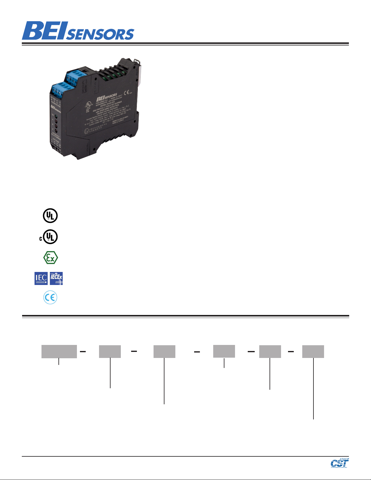
Intrinsic Safety Barrier Ordering Options for assistance, call 800.350.2727
Use this diagram, working from left to right to construct your model number (example: EM-DR1-IS-5-RTB-28V/V)
EM DR1
EM = Electronic Module, DIN Rail
mount
7230 Hollister Avenue | Goleta, CA | 93117
Tel: 805.968.0782 / 800.960.2726
www.beisensors.com
TYPE:
PACKAGE STYLE:
DR1 = 114.5 mm x 99mm x
22.5 mm
These c ommodities, te chnology or software i f exported fro m the United State s must be in accord ance
with the B ureau of Industr y, and Security, Export Administration regulations. D iversion cont rary to U.S.
law is prohibited.
IS= Intrinsically Safe
ISD = Intrinsically Safe with
Open Wire Detection (available
with 28V/V or 28V/5 supply
voltage/output)
IS RTB
5=5 VDC
FUNCTION
5
OUTPUT VOLTAGE TO
ENCODER
OUTPUT TERMINATION:
RTB =
RemoveTerminal
Block
VOLTAGE/OUTPUT:
28V/V = 12-28 VDC, Vout = Vin
28V/5 = 12-28 VDC, Vout = 5 volts
28V/OC = 12-28 VDC, Vout = Open Coll.
Specication No.: 02125-004
Rev 2-20-14
Page 1/ 2
Page 2
Intrinsic Safety Barrier
Specications
POWER SUPPLY / OUTPUT TYPE
Part Number Barrier Supply: Vs ±5% Output logic to Non-hazardous Area Apparatus
Line Driver
60004-002
60004-003 Vout = Vin
60004-004
60004-005 Vout = 5V
60004-006 Vout = Vin
Barrier Output
(Po)
12-28 VDC
Caution: Operation above or below barrier supply voltage (Vs) range noted will cause permanent damage to barrier
!
Class I, Gp D
Class II, Gps E,F,G
Group IIA
Voc (Uo) Isc (Io) Ca (Co) La (Lo) L/R Ratio Ca (Co) La (Lo) L/R Ratio Ca (Co) La (Lo) L/R Ratio
Vout = 5V
Open
Collector
BARRIER PARAMETERS
Class I, Gps C,D
Class II, Gps E,F,G
up to 100 mA source/sink
(TTL & RS422 compatible)
Line Driver
up to 100 mA source/sink
NPN
up to 80 mA sink
Line Driver
up to 100 mA source/sink
Open wire detect option
Line Driver
up to 100 mA source/sink
Open wire detect option
Group IIB
Class I, Gps A,B,C,D
Class II, Gps E,F,G
Group IIC
870 mW 9.48 VDC 367 mA 255 uF 2.1 mH 327 uH/Ω 27 uF 1.05 mH 160 uH/Ω 3.7 uF 0.26 mH 40.8 uH/Ω
INPUT TO BARRIER FROM ENCODER
Signals A, B, Z, A/, B/, Z/ differential or A,B,Z single-ended
Input Signal Impedance 500 Ω nominal (A to A/, B to B/, Z to Z/)
Input Signal level 4 VDC minimum, 6 VDC maximum
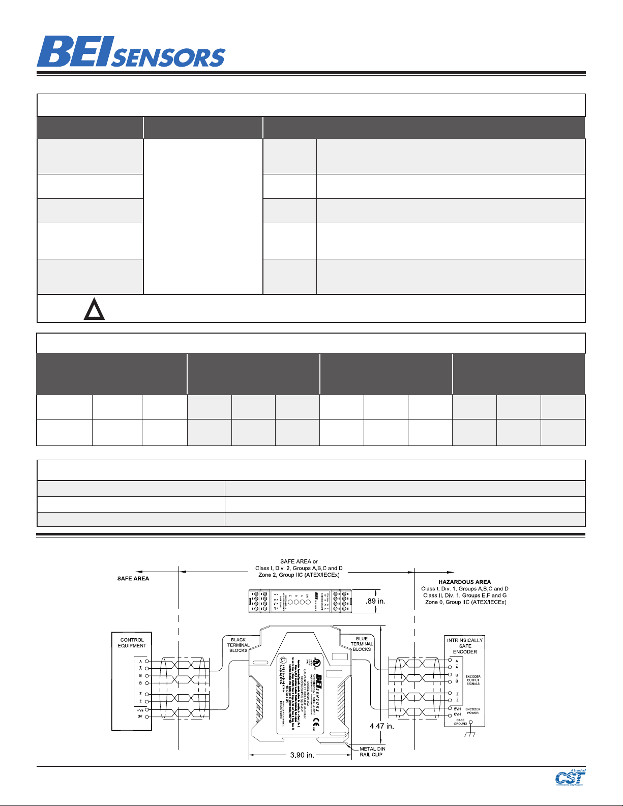
General Wiring Diagram (See BEI Sensors drawing 08067-003 for important details)
7230 Hollister Avenue | Goleta, CA | 93117
Tel: 805.968.0782 / 800.960.2726
www.beisensors.com
These c ommodities, te chnology or software i f exported fro m the United State s must be in accord ance
with the B ureau of Industr y, and Security, Export Administration regulations. D iversion cont rary to U.S.
law is prohibited.
Specication No.: 02125-004
Rev 2-20-14
Page 2/ 2
 Loading...