

Page 1
BEI Sensors SAS
Espace Européen de l’Entreprise
9, rue de Copenhague
IHO5
B.P. 70044 Schiltigheim
F 67013 Strasbourg Cedex
Tél : +33 (0)3 88 20 80 80
Fax : +33 (0)3 88 20 87 87
Mail : info@beisensors.com
www.beisensors.com
Web :
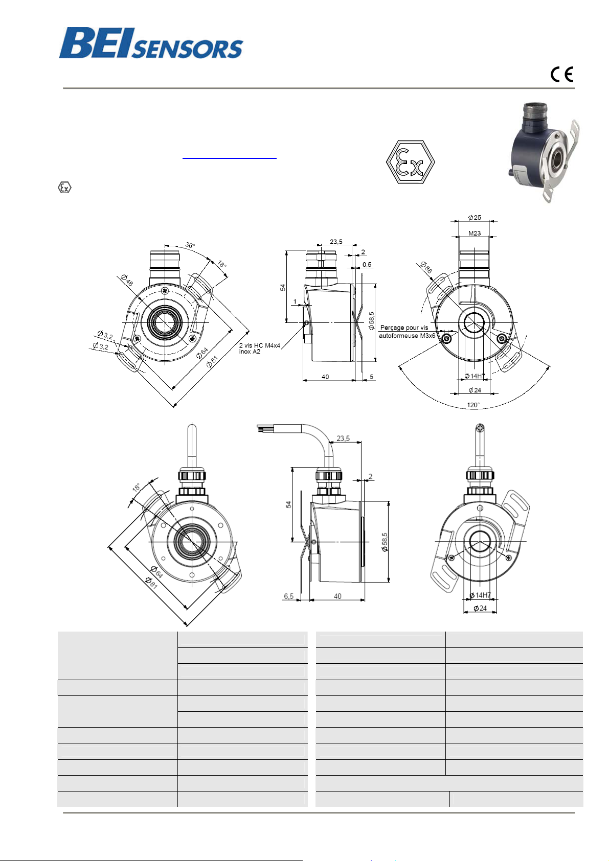
ATEX INCREMENTAL ENCODERS, IHO5 RANGE
Intrinsically safe encoders, specially designed for explosive GAZ or DUST atmospheres
For chemical applications (painti ng, solvent, fragrances and rubber), textile, food processing,
wood, petrochemical…
EC type examination certificate
Download from our website www.beisensors.com
LCIE 04 ATEX 6109 X
CE 0081
II 1 G/D Ex ia IIC/B T4 Ex iaD 20 T135°C
IHO5_14 connection G6R (radial M23), DAC 9445/015 mounted on the body
IHO5_14 connection G3R (radial cable), DAC 9445/015 monted onto the cover
axial
/ F
)
radial
Material
Cover : zinc alloy
Body : aluminium
Shaft : stainless steel
Shock (EN60068-2-27)
Vibration (EN60068-2-6)
500 m.s
100 m.s
-2
(during 6 ms)
-2
(55 … 2 000 Hz)
CEM EN 50081-1, EN 61000-6-2
Bearings 6 803 serie Isolation 1 000 V
Maximum load
Shaft iner tia
Torque
Axial : 20 N
Radial : 50 N
2,2.10-6 kg.m2
6.10-3 N.m
Weight (connector) 0,3 kg
Operating temperature - 30 ... + 70°C (encoder T°)
Storage temperature - 40 ... + 100°C
Protection(EN 60529) IP 65
Permissible max.speed 6 000 min-1 Torque (ring pressure screw) nominal: 1.5 N.m, break: 2.0 N.m
Continuous max. speed 6 000 min-1 Theoretical mechanical lifetime 109 turns (F
Shaft seal Viton 10N / 25N : 230 20N / 50N : 29
Changes possible without further notice - Version 080919
Page 2
BEI Sensors SAS
Espace Européen de l’Entreprise
9, rue de Copenhague
B.P. 70044 Schiltigheim
IHO5
F 67013 Strasbourg Cedex
ATEX INCREMENTAL ENCODERS, IHO5 RANGE
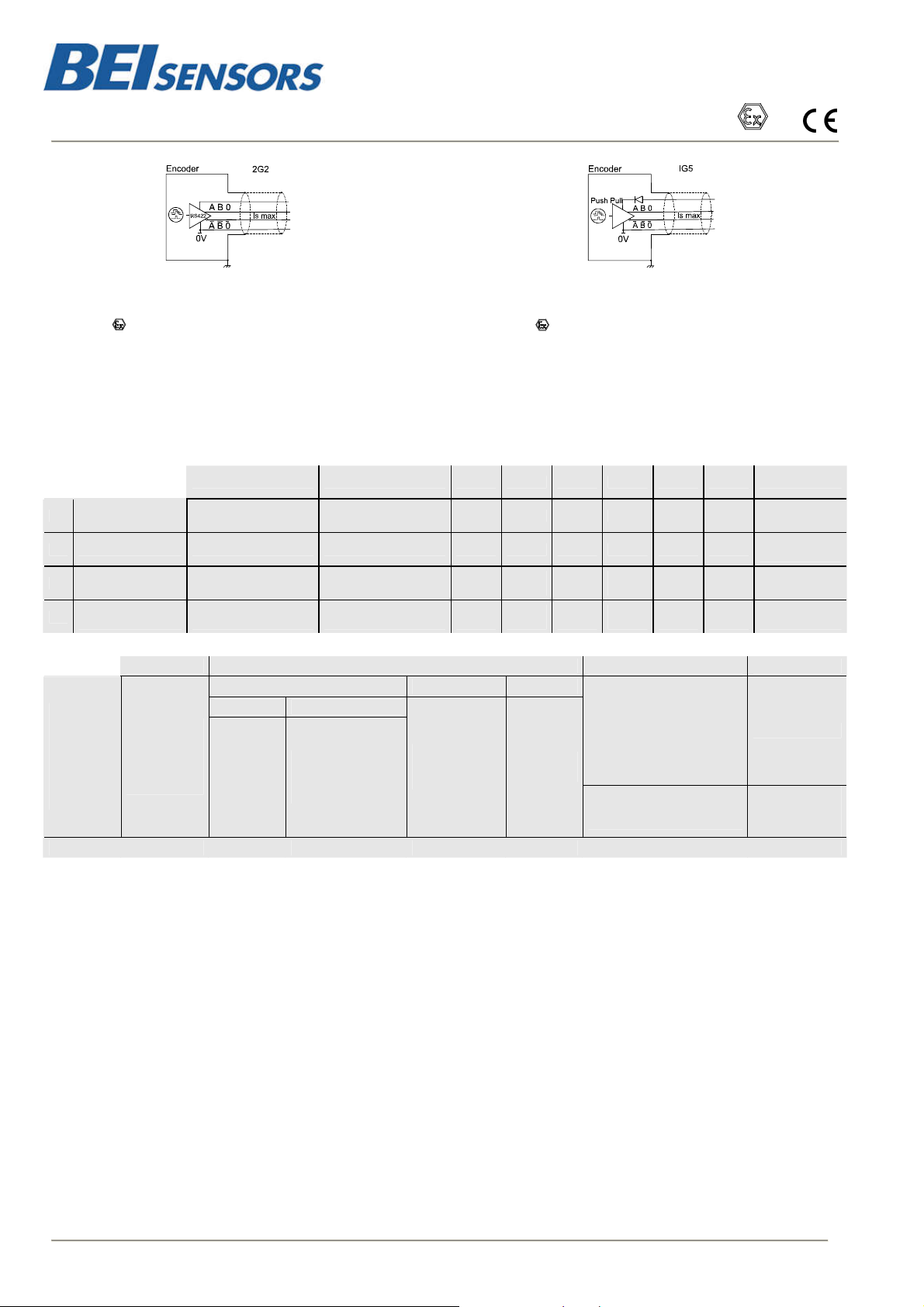
OUTPUT ELECTRONIC / SUPPLY - DIGITAL SIGNALS (SQUARE WAVE SIGNALS)
Tél : +33 (0)3 88 20 80 80
Fax : +33 (0)3 88 20 87 87
Mail : info@beisensors.com
www.beisensors.com
Web :
Suppl
y : 4.5 to 6Vdc Consumption : 75mA
ntern capacity: 1.3µF, intern inductance: 0mH
I
II 1 G/D Ex ia IIC T4, Ex iaD 20 T135°C
40 mA, TTL 20mA, F
RS422,
Barrier to be used for supply:
Ui<10V, Li<750mA, Pi<1.875W
Barrier to be used for each output:
STANDARD CONNEXION
Ui<10V, Li<200mA, Pi<0.5W
Protection against short circuits (for both electronics) and polarity inversions (except for 2G2)
Electronic 2G2
=300kHz
max
Electronic IG5
y : 8 to 12Vdc Consumption : 75mA
Suppl
I
ntern capacity: 1.3µF, intern inductance: 0mH
II 1 G/D Ex ia IIC T4, Ex iaD 20 T135°C
Push Pull 50m
A, F
Barrier to be used for supply:
i<16V, Li<750mA, Pi<3W
U
Barrier to be used for each output:
i<16V, Li<150mA, Pi<0.6W
U
=300kHz
max
- + A B 0 A/ B/ 0/ Ground
G6 12 pins CW 1 2 3 4 5 6 7 8
G8 12 pins CCW 10 + 11 2 + 12 8 5 3 1 6 4
PVC cable 8
G3
wires 8230/020
PUR cable 12
GP
wires 8230/050
ORDERING REFERENCE
Shaft
IHO5
Cover :
Zinc alloy
Body :
14 : 14mm
Reduction
hubs
available
Aluminium
Ex: IHO5 _ 14 // 2 G2 9 // 10 000 //
WH
white
WH white +
WH/GN white /green
Electronic : 2G2, IG5 Signals Resolution
Supply Output stage
2: 5Vdc
I: 8-12Vdc
G2 : driver RS422
G5 : driver push-pull
BN
brown
BU blue +
BN/GN brown / green
Digital signals (square) Connection Orientation
9 : A,A/,B,B/, 0,0/
(0 gated A&B)
GN
green
GY
grey
YE
yellow
BN
brown
80 000
max
GY
grey
RD
red
PK
pink
PK
pink
G6 : M23 12pins CW
G5 : M23 12pins CW
G8 : M23 12 pins CCW
G1 : solenoid valve 4pins
G2 : DIN 5 pins
GD : DIN 8 pins
G3 : PVC cable 8 wires
GP : PUR cable 12 wires
BU
blue
GN
green
black
GP R050
RD
red
BK
Connector
body
Connector
body
General
shielding
General
shielding
R : radial
Example :
R020: radial
cable 2m
Available resolutions (2G2 and IG5): 50 60 100 120 125 127 150 180 200 240 250 256 300 314 360 375 400 500 512 600 720 750 768 800
927 1000 1024 1200 1250 1280 1440 1500 1800 2000 2048 2400 2500 3000 3600 4000 4096 5000
Interpolated available resolutions (2G2 only): 1080 2560 2880 3072 4320 5120 5760 6000 7200 7500 8000 8192 9000 10000 10240 10800
12000 12500 12288 14400 15000 16000 16384 18000 20000 20480 24000 25000 28800 30000 32000 32768 36000 40000 40960 43200 48000
49152 50000 57600 60000 64000 65536 80000
NEVER CONNECT/DISCONNECT OR OPEN THE ENCODER UNDER POWER SUPPLY IN DUST ENVIRONMENTS.
RESPECT THE MOUNTING AND THE MECHANICAL RESTRICTIONS IN ORDER TO REMAIN IN LINE WITH THE MAXIMAL SURFACE TEMPERATURE
VALUE ALLOWED BY THE CLASS T4 REQUIREMENTS
LCIE 04 ATEX 6109 X : CE certification of Type for the encoder :
Operating temperature : -30°C to +70°C
The components of the device are intrinsically safe : they can be used in explosive atmospheres. The supply and outpu circuits can
only be connected to associated devices which are intrinsically safe and that are certified by type (ia) or (ib). These devices must
have electrical parameters that have a compatible supply with the above mentioned eletronics
LCIE 04 ATEX 6155 X : CE certification of Type for the encoder’s system (encoder in association with a BEI barrier) :
Operating temperature : barrier -20°C to +40°C and encoder -30°C to +70°C
System classification : Ex ia IIC T4 Ex iaD 20 T135°C
The interconnecting cables have to be sufficiently protected against damage and have to be separated from the non intrinsically
safe circuits. They are described in the norm EN50020 paragraph 6.3, with the following characteristics C=100pF/m and L=1.2µH/m, or
with cables with other C and L values, with respect to the maximum authorized :
Gases : Ca=3.9µF and L=0.4mH
Dust : Ca=38.7µF and L=0.8mH
Made in FRANCE
Changes possible without further notice - Version 080919
Page 3
BEI Sensors SAS
Espace Européen de l’Entreprise
9,
rue de Copenhague
IHO5
B.P. 70044 Schiltigheim
F 67013 Strasbourg Cedex
Tél : +33 (0)3 88 20 80 80
Fax : +33 (0)3 88 20 87 87
Mail : info@beisensors.com
www.beisensors.com
Web :
ATEX INCREMENTAL ENCODERS, IHO5 RANGE
1) Déclaration de conformité CE
2) Nous, société BEI Sensors, certi fions que ce matériel :
capteurs antidéflagrants, type
IHM5, IHM9, IHO5 et IHK5
3) Avec les inscriptions suivantes :
CE 0081 II 1 G/D, Ex ia IIB ou IIC T4, Ex iaD 20
T135°C
A été conçu et fabriqué conformément à la directive
applicable suivante :
ATEX directive 94/9/CE
Directive CEM 89/336/CEE
4) La certification a été obtenu grâce à l’application
des normes suivantes :
EN 50014 (1997) + amendements 1 et 2, EN 50020 (2000),
EN 13980 (2002), CEI 61241-0-Ed.1 (2004), CEI 61241-11-Ed.1
(2004), EN 60079-11
5) Une attestation d’examen CE de type a été obtenu :
LCIE 04 ATEX 6109 X
et une notification :
LCIE 03 ATEX Q8060
6) L’application des normes suivantes a participé à
l’obtention de la certification :
EN 50081-1, EN 55022 classe B, EN 55014, EN 61000-6-2,
CEI 61000-4-2, CEI 61000-4-3, CEI 61000-4-4, CEI 61000-45, CEI 61000-4-6, CEI 61000-4-8, CEI 61000-4-11
7) L’organisme notifié responsable du suivi de la
directive ATEX est le
LCIE,B.P.8, F92260 Fontenay-aux-Roses
Numéro d’identification : 0081
8) La société chargée de la certification CEM est
nommée ci-après :
GRME, Cellule CEM, B.P.8, 68840 Pulversheim
9) Nous certifions que nos produits désignés ci-dessus
sont conformes à la directive et aux normes spéci fiées
Date : ATEX Certified Product Approved Person
1) Declaration of conformity EC
2) We, BEI Sensors, certify that this material : sensor
intrinsically safe standard
IHM5, IHM9, IHO5 and IHK5
3) With the following inscriptions :
CE 0081 II 1 G/D, Ex ia IIB or IIC T4, Ex iaD 20
T135°C
Conceived and manufactured has the directive
applicable following :
ATEX directive 94/9/CE
Directive CEM 89/336/CEE
4) Certification to summer obtained thanks to the
application of the standards :
EN 50014 (1997) + amendments 1 and 2, EN 50020 (2000),
EN 13980 (2002), CEI 61241-0-Ed.1 (2004), CEI 61241-11-Ed.1
(2004), EN 60079-11
5) EC type examination certificate was obtained :
LCIE 04 ATEX 6109 X
and a notification :
LCIE 03 ATEX Q8060
6) The application of the following standards too k part
in obtaining certication :
EN 50081-1, EN 55022 classe B, EN 55014, EN 61000-6-2,
CEI 61000-4-2, CEI 61000-4-3, CEI 61000-4-4, CEI 61000-45, CEI 61000-4-6, CEI 61000-4-8, CEI 61000-4-11
7) The notified organization responsible for the followup of the directive ATEX is the
LCIE,B.P.8, F92260 Fontenay-aux-Roses
Identification number : 0081
8) The company in charge of certification CEM is
named :
GRME, Cellule CEM, B.P.8, 68840 Pulversheim
9) We certify that our indicated products so above are in
conformity with the directive and the specified standards
Changes possible without further notice - Version 080919
 Loading...