

Page 1
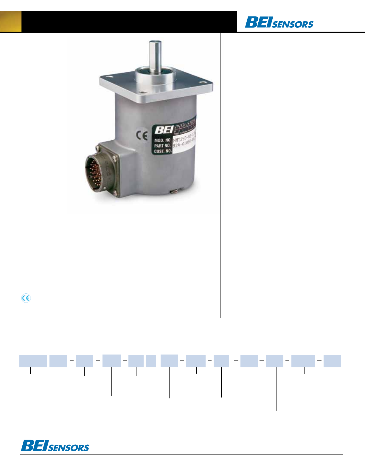
HMT25 Absolute Multi-Turn Encoder
The HMT25 geared
multi-turn encoder
provides absolute posi-
tion information over
multiple turns of the
input shaft. It keeps
track of the exact posi-
tion even during periods of power loss without the need for a battery backup. The
HMT25 series is capable of outputs up to 4096 counts per turn and can count up to
4096 turns—a total of 24 bits or 16,777,216 positions. Units are enclosed in a 2.5-
inch diameter sealed package to withstand rugged environments and they carry an
IP 66 environmental rating. These encoders meet the long travel and high resolution
requirements of robotics, rolling mills, rotary tables, cable winding, printing, convert-
ing and material handling systems.
The H25 Incremental Encoder is avail able with the following certification:
EN 55011 and EN 61000-6-2
Mechanical Specifications
Shaft Diameter: 0.375” (0.5” optional)
Flat on Shaft: 0.80” long x 0.030” deep
Shaft Loading: 40 lbs axial, 36 lbs radial (90 lbs axial
and 80 lbs radial with 0.5” shaft)
Shaft Runout: 0.0005 TIR at midpoint of shaft
Starting Torque at 25°C: 2.5 in-oz (max)
Bearings: Dual, preloaded, Class ABEC 7
Shaft Material: 416 stainless steel
Bearing Housing: Die cast aluminum with protective finish
Cover: Die cast aluminum
Bearing Life: 1 x 10¹⁰ at 10% rated load
Maximum RPM: 6,000 (see frequency response, below)
Moment of Inertia: 4.3 x 10⁻⁴ oz-in-sec
Weight: 16 oz nominal
2
Electrical Specifications
Code: Natural binary, gray code or SSI
Counts per Shaft Turn: 4096, 12 bits
Number of Turns: up to 4096, 12 bits
Supply Voltage: 5–28 VDC
Current Requirements: 130 mA typical + load, 250mA (max)
Voltage/Output: (See note 3)
28V/V: Line Driver, 5–28 VDC in, V
28V/5: Line Driver, 5–28 VDC in, V
28V/OC: Open Collector, 5–28 VDC in, OC
SSI: 5–28 VDCin/5V
Frequency Response: 100 kHz
Protection Level: Overvoltage, reverse voltage.
Outputs short-circuit protected (1 minute max)
Output Termination Pinouts: See Tables, back page
(see back page)
out
= Vin
out
= 5 VDC
out
out
Environmental Specifications
Enclosure Rating: IP66
Temperature: Operating, 0° to 70° C; Extended, -40° to +85°C;
Storage, -20° to 90° C (to -40° if extended range is called out)
Shock: 50 g’s 11 msec
Vibration: 5 to 2000 Hz @ 20 g’s (see special note back page)
Humidity: 98% Non-condensing
NOTES & TABLES: All notes and tables referred to in the text
can be found on the back of this page.
HMT25 Multi-Turn Encoder Ordering Options FOR ASSISTANCE CALL 800-350-2727
Use this diagram, working from left to right to construct your model number (example: HMT25D-SS-12X12GC-28V/V-CW-SM18/32).
All notes and tables referred to can be found on the back of thispage.
HMT25
TYPE:
Heavy Duty
Multi-trun
2.5 inch Dia.
HOUSING :
D = Square Flange
E = Servo mount
These commodities, technology or software if exported from the United States must be in accordance with the Bureau of Industry, and Security, Export Administration regulations. Diversion contrary to U.S law is prohibited.
FACE MOUNTS:
F1 = 3,10–32,1.875 BC
F4 = 3, 6–32, 2.00 BC
CONFIGURATION:
SS = Shaft Seal
Tel: 805-968-0782 /800-350-2727 | Fax: 805-968-3154 / 800-960-2726
7230 Hollister Ave., Goleta, CA 93117-2807 | www.beisensors.com
COUNTS PER TURN:
12 = 4096 counts
SHAFT SEAL
See note 2
X
NUMBER OF TURNS:
4 = 16 turns
8 = 256 turns
12 = 4096 turns
CODE TYPE:
GC = Gray Code
NB = Natural Binary
VOLTAGE/OUTPUT:
28V/V = 5–28V
28V/5 = 5–28V
28V/OC = 5–28V
S3 = SSI Compatible
DIRECTION OF COUNT:
CW = Clockwise increasing count
CCW = Counter clockwise
increasing count
in/out
in/5Vout
in/OCout
A1 = 4–20mA
A2 = 0–10V
OUTPUT
TERMINATION:
E = End
S = Side
CONNECTOR:
M18/32 = 32 pin
Parallel output
M18 = 10 pin
(A1, A2 and S3 only)
SPECIAL FEATURES:
S= Special features
specified on purchase
order (consult factory)
See note 4
Specification No. 02083-001 Rev.08-11
Page 2
HMT25 Absolute Multi-Turn Encoder
Tables and Figures
HMT25 Output Terminations for Parallel Output
PIN FUNCTION
A T11 (MSB)
B T10
C T9
D T8
E T7
F T6
G T5
H T4
(1) Parallel output uses a MS3112E18-32P, 32 Pin connector on the encoder body (2) TXX = Turns
counts, FXX = Fine resolution counts
(2)
PIN FUNCTION
J T3
K T2
L T1
M T0 (LSB)
N F11 (MSB)
P F10
R F9
S F8
(2)
PIN FUNCTION
T F7
U F6
V F5
W F4
X F3
Y F2
Z F1
a F0 (LSB)
(2)
1
PIN FUNCTION
b N/C
c LATCH
DIR CONTROL
d
ENABLE (Option)
e
f N/C
g 0 V
h +V
j CASE GND
HMT25 Output Terminations for Optional 24 Bit SSI Ouput
TERM BOARD
FUNCTION CABlE CONNECTOR* (H38 & H40 ONlY)
H38 H40
DATA+ YEL A 4 1
DATA- WHT/YEL H 7 7
CLOCK+ BLU B 5 2
CLOCK- WHT/BLU I 8 8
DIRECTION OF COUNT ORN C 6 3
ENABLE (Optional) VIOLET E 9 —
RESET (Optional) WHT/ORN J 10 9
+V (SUPPLY VOLTAGE) RED D 3 4
0 V (CIRCUIT COMMON) BLK F 2 5
CASE GROUND GRN G 1 6
*Connector is an MS3102E18-1P, 10-pin connector on the encoder body and mates to an MS3106F181S connector or can be used with a standard cable/ connector assembly, BEI part 924-31186-18XX.
(Where XX = 10, 20, or 30 for a 10, 20 or 30 foot cable length.)
Direction of Count: The HMT25 comes standard with a Direction of Count bit. Normal operation is CW
increasing count when viewed from the shaft end. This pin is normally pulled HI internally. To reverse the count
(2)
direction, this pin must be pulled LO (Circuit Common). Optionally this can be designated as CCW increasing
count when HI, in which case LO will be CW increasing count.
Latch: Outputs are active and provide continuous information when this pin is HI. When this pin is pulled LO (Circuit
Common) the outputs are latched at the logic state that is present when the latch is applied and will stay latched until
this pin is no longer LO. This pin is pulled HI internally.
Enable (optional): This option allows the operator to momentarily deactivate the outputs from the encoder. This
may be useful in instances where the outputs from several different encoders must be sampled independently.
Output is active when this pin is HI. When pulled LO (Circuit Common) all outputs go to high impedance state (Tristate) and are inactive until the LO state is removed. This pin is pulled HI internally. To order this option on the HMT25
make sure the model number has –S on the end, followed by the description, –S = output enable.
RESET (Optional): The Reset pin (Pin J) is normally HI and is pulled up internally to the positive supply voltage.To activate the Reset function, Pin J must be pulled LO by connecting it to signal common for 1 second or
greater. This causes the present encoder position to be stored into non-volatile memory as an offset value and
the output of the encoder is then set to the value of “0”. The encoder will retain this offset even if the power
is turned off and on again. A new “0” position can be set by rotating the encoder shaft to a new position and
then activating the Reset pin again. To order this option for the HMT25, make sure the model number has –S
on the end followed by the description, –S = Reset.
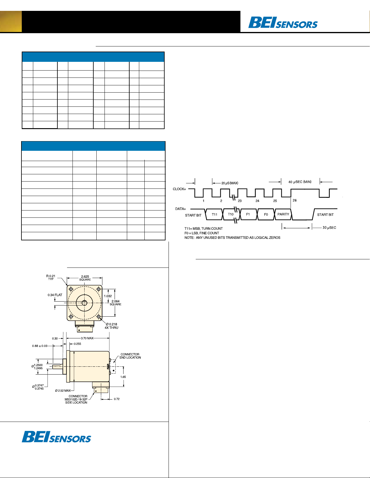
24 Bit, SSI Compatible Output Timing
Notes
Dimensions
Special note on vibration testing:
Test profile is 0.3 g’s ramp to 20 g’s from 5 to 40 Hz and 20 g’s from 40 Hz to 2000 Hz.
Tel: 805-968-0782 /800-350-2727 | Fax: 805-968-3154 / 800-960-2726
7230 Hollister Ave., Goleta, CA 93117-2807 | www.beisensors.com
1. Mounting is usually done either using the
D-style square flange mount, E- or G-style servo
mounts, or one of the standard face mounts, F1
for example. Consult factory for additional face
mount options.
2.The shaft seal is recommended in virtually all
installations. The most common exceptions are
applications requiring a very low starting torque
or those requiring operation at both high temperature and high speed.
3. Output IC’s: Output IC’s are available as
either Line Driver (LD) or NPN Open Collector
(OC) types. Open Collectors require pull-up resistors, resulting in higher output source impedance (sink impedance is similar to that of line
drivers). In general, use of a Line Driver style
output is recommended. Line Drivers source or
sink current and their lower impedance mean
better noise immunity and faster switching
times. Warning: Do not connect any line driver
outputs directly to circuit common/OV, which
may damage the driver. Unused outputs should
be isolated and left floating. Our applications
specialists would be pleased to discuss your
system requirements and the compatibility of
your receiving electronics with Line Driver
type outputs.
28V/V: Multi-voltage Line Driver (7272*): 100
mA source/sink. Input voltage 5 to 28 VDC +/5% standard (Note: V
TTL compatible when used with 5 volt supply.
Supply lines are protected against overvoltage to
60 volts and reverse voltage. Outputs are short
circuit protected for one minute. Supply current
is 120 mA typical (plus load current). This is
= Vin). This driver is
out
the recommended replacement for 3904R and
7406R open collector outputs with internal pullup
resistors. It is also a direct replacement for any
4469, 88C30, 8830 or 26LS31 line driver.
28V/5: Multi-voltage Line Driver (7272*): 100
mA source/sink. Input voltage 5 to 28 VDC +/5% standard, internally regulated with 5V (TTL
compatible) logic out. Supply lines are protected
against overvoltage to 60 volts and reverse voltage. Outputs are short circuit protected for one
minute. Supply current is 90 mA typical (plus
load current). Note: Limit encoder load to 2.5W
max at ambient. Example at 12 VDC: 2.5W/
(+12VDC minus +5VDC) = 357 mA total allowed
current. Consult factory for your specific requirements.
28V/OC: NPN Open Collector (3904*, 7273*).
Current sink of 80 mA max. Current sourced
by external pull- up resistor. Output can be
pulled up to voltage other than supply voltage
(30 V max). Input voltage 5 to 28 VDC +/- 5%
standard. Supply current is 120 mA typical. This
replaces prior IC’s with designations of 3904,
7406, 3302, 681 and 689.
4. Special –S at the end of the model number is
used to define a variety of non-standard features
such as special shaft lengths, voltage options,
or special testing. Please consult the factory to
discuss your special requirements.
* Products manufactured prior to April 2007 used the line driver IC number instead
of voltage output in model number.
 Loading...