

Page 1
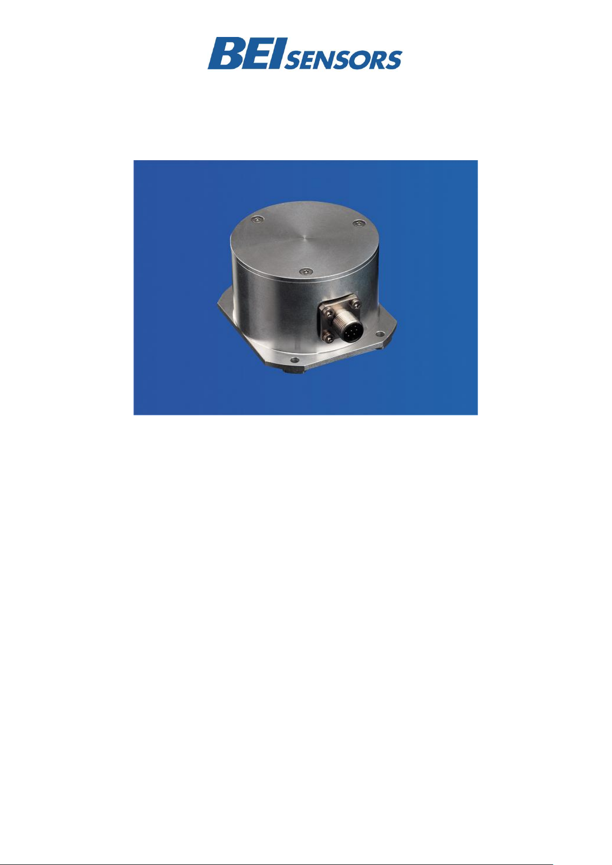
INCLINOMETER
RS232 – CURRENT
Main Features
- Two axis digital inclinometer
- Angle measurement range of +/-5°, +/-15°
and +/-30°, Resolution up to 0.001°
- Interface: RS232, Code: ASCII,
Current 4 to 20mA
- Housing: 70 mm
Programmable Parameters
- Transmission mode:
Polled Mode, Cyclic Mode
- Cycle Time
- Setting of zero point
- Baudrate 2.4 to 56 KBaud
Applications
- Structural engineering
- Leveling techniques
- Measuring techniques
- Inclinations
- Mechanical Structure
Electrical Features
- Linear and temperature compensated
characteristic line
- Microprocessor controlled
- Polarity inversion protection
- Over-voltage-peak protection
- Highly integrated circuit in
SMD-technology
Page 2
INCLINOMETER
RS232 – CURRENT
Model
INC 5
INC 15
INC 30
Measuring range
+/- 5°
+/- 15°
+/- 30°
Resolution digital
0.001°
0.001°
0.01°
Resolution analog
0,001°
0,005°
0,01°
Accuracy Digital1)
+/-0,01°
+/-0,01°
+/-0,02°
Accuracy Analog1)
+/-0,05°
+/-0,05°
+/-0,05°
Temperture Gradient2)
+0.001°/K
+0.002°/K
+0.003°/K
Inclination angle in x and y1)
+/-15°
+/-40°
+/-60°
Damping period 5° > 0°
Typical 1 s 10 %, 2 s 1 %, 3 s 0.1 %
Digital interface
RS232 format ASCII
Baud rate
Max. 56 k
Analog interface
4 to 20mA, 0°= 12mA, Load 300 Ohm
Supply voltage4)
10 to 30 V DC (absolute limits)
Current consumption
Typical 50 mA
EMC
Emitted interference: EN 61000-6-3
Noise immunity: EN 61000-6-2
Electrical lifetime
> 105 h
1 Technical Data
1.1 Electrical Data
1) T = +25°C, 90% total measurement range
2) e.g. temperature drift AGS005 (T= 0°C up to +55°C) = 55K * 0,001°/K = 0,055°
3) Supply voltage is applied.
4) Inclinometers should be connected only to subsequent electronics whose power supplies comply with EN 50178 (protective low
voltage)
Page 2 Inclinometer RS232 – Current Datasheet Version: 20130503
Page 3
INCLINOMETER
RS232 – CURRENT
Housing
Aluminum
Lifetime
> 105 h
Shock
A=30g ; t= 11 ms, halfsine ; EN 60068-2-27
Vibration
10 to 150 Hz, 2,5 mm amplitude, 5 g const. Acceleration,
1 Octave /Minute ; EN 60068-2-6
Weight (standard version)
350 g
Operating/ Storage temperature
-40 to +85°C
Humidity
98 % (without liquid state)
Protection class
IP 67 (connected); EN 60529
1.2 Mechanical Data
1.3 Environmental Conditions
Page 3 Inclinometer RS232 – Current Datasheet Version: 20130503
Page 4
INCLINOMETER
RS232 – CURRENT
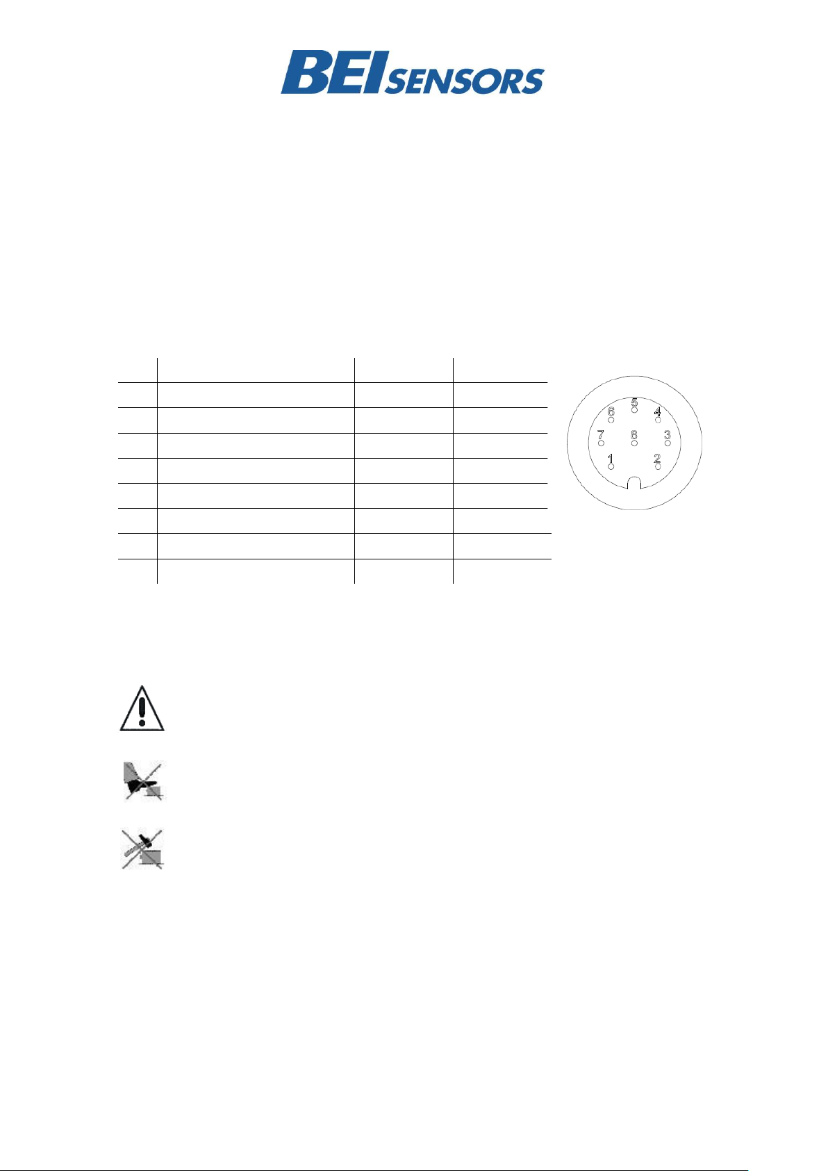
Pin
Description
P8F-Cable
CRW-Cable
1
+UB Supply voltage
white
white
2
RxD
brown
brown
3
TxD
green
green
4
Ground (Supply)
yellow
yellow
5
X-Output
grey
grey
6
S-Ground
pink
pink 7 Y-Output
blue
red 8 –
red
–
Front view of housing
Connector inclinometer
2 Installation
2.1 Electrical Connection
The inclinometer is connected via 8 pin round connector or a cable
2.2 Connector Assignment
Output signal (X, Y) analog current 4 to 20 mA (+x,y° to -x,y°)
Installation Instructions
Do not connect the inclinometer under power!
Do not stand on the inclinometer!
Avoid mechanical load!
Page 4 Inclinometer RS232 – Current Datasheet Version: 20130503
Page 5
INCLINOMETER
RS232 – CURRENT
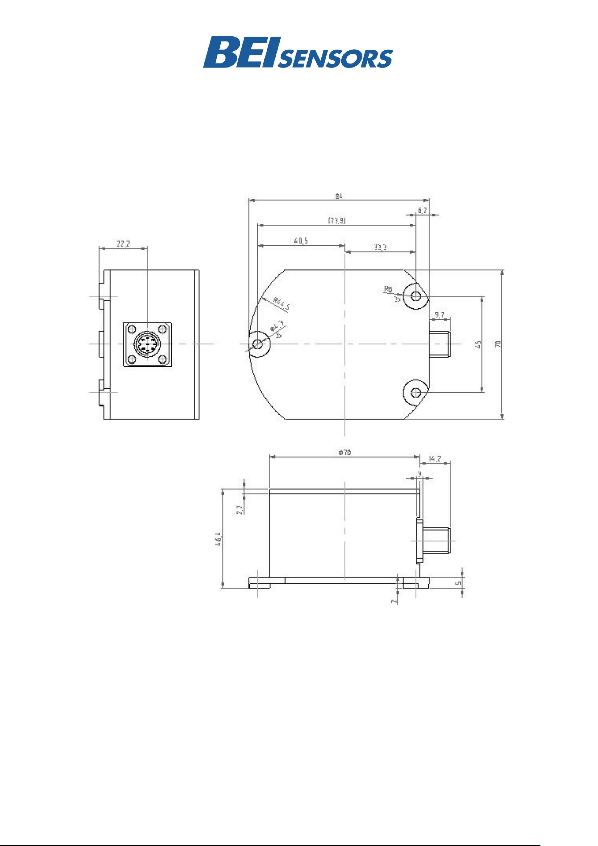
3 Mechanical Drawings
Dimension Housing (mm)
Page 5 Inclinometer RS232 – Current Datasheet Version: 20130503
Page 6

INCLINOMETER
RS232 – CURRENT
Reference edge, base plate side
4 Reference Level
The inclinometer has a mounting reference angle
(black line) for an optimal mounting, which is
parallel to the x-axis. This reference angle must be
placed exactly parallel to the object to be
measured, to prevent or minimize any mechanical
offset/cross sensitivity.
Reference angle of the inclinometer, top view.
Page 6 Inclinometer RS232 – Current Datasheet Version: 20130503
Page 7

INCLINOMETER
RS232 – CURRENT
+ y
- x
+ x
- y
Lateral axis
Longitudinal axis
5 Mounting and Installation Instruction
The inclinometer is designed for a horizontal
mounting, i.e. the base plate of the inclinometer
with the three mounting holes needs to be placed
on the horizontal plane of the object to be
measured. It can be mounted with M4 screw or
smaller.
5.1 Installation
Prior to installation, please check for all connection
and mounting instructions to be complied with.
Please also observe the general rules and
regulations on low voltage technical devices. Avoid
shock and vibration during installation, as these
5.2 Measurement
The measurement of the tilt angle of the single
measurement axis is carried out over the
respective longitudinal and lateral axis of the
View of male socket Side view
The mounting surface must be plane and free of
dust and grease. We recommend cheese head
screws with metrical thread M4 for the mounting.
Maximum fastening torque for the mounting screws
is 10 Nm.
could corrupt the measurement results. Inclination
sensors that base on a fluidic measurement
principle are optimal for static measurements and
suitable to only a limited extent of dynamic
measurement.
inclination sensor. Reference is always the
horizontal plane.
Page 7 Inclinometer RS232 – Current Datasheet Version: 20130503
Page 8

INCLINOMETER
RS232 – CURRENT
Description
Type Key
Absolute Inclinometer
INC-
_ _ _
-2-S _ 1-H0-
_ _ _
Measuring range
005
015
030
Number of axis
RS232
without Interface
Volltage interface
Current interface
PWM
Switch
O
V
C
P
S
Version
Mounting
Dynamic
Horizontal
2 mPas
Connection
plug, 8 pins
1 m cable exit
P8M
CRW
Optionen
–
6 Models/Ordering Description
Page 8 Inclinometer RS232 – Current Datasheet Version: 20130503
Page 9

INCLINOMETER
RS232 – CURRENT
7 Serial Interface RS 232
Communication with the sensor is done through a
standardized RS-232 interface. Data transmission
is effected in duplex mode. The baud rate is fixed
by 9600 baud. After Power On the sensor is
sending continuous the angle values in degrees
(°). In the setup level several settings can be
permanently modified. If the continuous mode was
permanently changed to the polling mode, the
sensor will send after Power On a start information
with actual parameters. On error no angle values
are sending and after Power On an error message
was add to the start information.
Page 9 Inclinometer RS232 – Current Datasheet Version: 20130503
Page 10

INCLINOMETER
RS232 – CURRENT
…
X=+00.430
Y=-00.084
…
8 Programming Instructions
8.1 Basic Settings
After Power On, the sensor is in the user level. In
factory setting (=Free running mode) every 100ms
the current angle values are continuously supplied
with a baud rate of 9600 bd. In the Setup-level
several settings can be changed permanently such
as query or free running mode, output rate, baud
8.2 Interface parameter
- 9600 Baud , 8 data bits, parity even, 1 stop bit,
The baud rate can be adjusted to different values in the Setup-level.
Structure:
rate and angle offset. If query mode instead of free
running mode is selected, the sensor will send
start information with the current settings after
Power On. In case of errors no angle values will be
provided and after Power On an error message will
be added to the start information.
Baud rate: 9600 Baud (factory setting, changes in Setup-Mode possible)
Format ASCII, 8 data bits, 1 stop bit, parity even
Length: 22 byte
Display: <D0 ... D21>
D0 ... D10 = “X=±xx.xxx“, <CR>, <LF>
mit D2 = sign (+ or -)
mit D5 = point
D11 ... D21 = “Y=±xx.xxx“, <CR>, <LF>
with D13 = sign (+ or -)
with D16 = point
Display Example:
Page 10 Inclinometer RS232 – Current Datasheet Version: 20130503
Page 11

INCLINOMETER
RS232 – CURRENT
Instruction
To the
sensor
Response sensor
Description
activate temporary polling
mode
„f“
„f“
the continuous sending of
angle values is stopped,
instructions can be sent to the
sensor
activate temporary continuous
mode
„F“
„X=vxx.xxx“, CR, LF,
„Y=vxx.xxx“, CR, LF,
„X= . . .
X angle in °
Y angle in °
with „±” = „+“ or „-“,
one string contains x and y
value
read angle values
at one-timeErreur ! Source
du renvoi introuvable.
„R“
„X=vxx.xxx“, CR, LF,
„Y=vxx.xxx“, CR, LF,
X angle in °
Y angle in ° with „±” = „+“ or „-“
switch to the setup level
3) 4)
”prog”
”P“
Sensor is at setup level
show active level
“*“
“Ux“ or
”Sx“
„U“ means Sensor is at User
level
„S“ means Setup-level is
active,
with „x“ Output-Mode of
Sensors „U“ / „I“ / „P“ / „S“
9 Commands in User Level
1) In free running mode measurement data is continuously displayed. In query mode measurement and display is only once on
command.
2) After reset or new Power On after an interruption of power supply, the sensor will be in user-level again with the original setup or with
the setup changed in the setup level.
3) Only possible in query mode (=free running mode deactivated).
4) The Input of „prog“ must take place within 20 sec.
Page 11 Inclinometer RS232 – Current Datasheet Version: 20130503
Page 12

INCLINOMETER
RS232 – CURRENT
Instruction
To the sensor
Response sensor
Description
activate permanent
polling mode1)
“f“
“f“
the continuous sending of
angle values are
permanent stopped,
instructions can send to
the sensor
activate permanent
continuous mode1)
“F“
„X=±xx.xxx“, CR, LF,
”Y=±xx.xxx“, CR, LF,
”X= . . .
continuous sending of
X angle in °
Y angle in °
with „±” = „+“ or „-“
set rate of data
transmission for
continuous mode
2) 3) 4)
“O“
<Code transmission
rate>
“O”
<Code transmission
rate>
Echo,
Code transmission rate
or „E“ for Error, if the
code is outside defined
values
read angle values at
one-time2)
“R“ same as at user level
read version2)
“V“
“AGSxxx-2-Sx“, CR,
LF
”SN:xxxx-xxx“, CR,
LF
”HV:xx.x“ , CR, LF
”SV:xx.x“ , CR, LF
type of Sensor
serial number
HW Version internal
sensor
SW Version
offset adjust of the
specified axis
2) 3)
“n“
”x“ or ”y“
“n“
”OffsetX=±xx.xxx“ or
”OffsetY=±xx.xxx“
the actual angle of
specified axis is set to
zero, ±xx.xxx is the
internal offset in
degree
reset offset adjust
2) 3)
“N“
“N“
the offset adjust was
reset to the original value
Set Baud rate
2) 3) 6)
“B“
<Code Baud rate>
“B“
<Code Baud rate>
Echo, Code Baud rate or
„E“ for Error, if the code
is outside defined values
Filter deactivated
„M0“
„M0“
all filters are deactivated
Moving Average
Filter
10)
„M1“, “mm“
„M1mm“
Filter: Moving Average
Filter is activated
10 Setup Level
The Setup level is active until Power On or Reset.
All settings taken in the setup level are stored in
the EEPROM and permanent available also after
Power down.
Page 12 Inclinometer RS232 – Current Datasheet Version: 20130503
Page 13

INCLINOMETER
RS232 – CURRENT
Exponential Filter
10)
„M2“, „tt“
„M2tt“
Filter: Exponential Filter
is activated
Set switch angle for
one axis
2) 3) 7) 8)
“Sx“
<switch angle> or “Sy“
<switch angle>
“Sx“ or “Sy”
<switch angle>
Echo, switch angle or „E“
for Error, if the angle is
outside admissible range
Set hysteresis for
switching point in both
axis
2) 3) 7) 9)
“Sh“
<hysteresis>
“Sh“
<hysteresis>
Echo, hysteresis or „E“
for Error, if the angle is
outside admissible range
show active level2)
“*“ same as at user level
Reset2)
“q“
“q“
Software-Reset will be
executed
1) in the continuous mode the sensor is sending continuous angle values, in the polling mode the sensor is sending one answer after
an instruction
2) only possible at polling mode.
3) for activating a reset or power fail restart is necessary
4) for Code transmission rate see
5) Table 1 <Code transmission rate>
6) for Code baud rate see Erreur ! Source du renvoi introuvable.
Attention! A reset of the baud rate to a default value is not possible. If the user forgets the adjusted baud rate, the new value must
be detected by testing.
7) this instruction is only effectual at sensors with switch output,
8) <switch angle>: three digits from “001” until “300” for the angle in tenths of a degree, max working range of the sensor. Default value
is 025 == 2,5°
9) <hysterese>: two digits from “01” until “99” for the stitching hysterese in tenths of a degree, max working range of the sensor, Default
value is 01 = 0,1°
10) Formulas for Filter :
- Moving Average Filter „M1“, „mm“ (possible values mm = 02 to 40, with mm = 00 is moving average filter deactivated): Output
value = Average over last mm values.
- Exponential Filter „M2“, „tt“ (first order low pass filter, possible values tt = 02 to 40, with tt = 00 is exponential filter deactivated):
Output value = ( old output value * (tt-1) / tt ) + (value / tt )
Page 13 Inclinometer RS232 – Current Datasheet Version: 20130503
Page 14

INCLINOMETER
RS232 – CURRENT
<Code transmission rate>
Strings per second, 1 string contains x and y-value
“0“
reserved
“1“
25 Strings/s1)
“2“
10 Strings/s, Default value2)
“3“
5 Strings/s
“4“
2 Strings/s
“5“
1 Strings/s
“6“
0,2 Strings/s
“7“
0,1 Strings/s
“8“, “9”
not defined
<Code Baud Rate>
Baud rate
“0“
2400 Baud
“1“
4800 Baud
“2“
9600 Baud, Default value
“3“
19200 Baud
“4“
38400 Baud
“5“
57600 Baud
“6“, “7“, ”8“, ”9“
not defined
<Code transmission rate>
1) only allowed with baud rate of at least 9600 Bd
2) only allowed with baud rate of at least 4800 Bd
<Code Baud Rate>
Page 14 Inclinometer RS232 – Current Datasheet Version: 20130503
Page 15

INCLINOMETER
RS232 – CURRENT
Instruction
To the sensor
Response sensor
Description
„X=±xx.xxx“, CR, LF,
”Y=±xx.xxx“, CR, LF,
”X= . . .
continuous sending of
angles
activate temporary
polling mode
”f”
“f“
the continuous sending
of angle values are
stopped, instructions
can send to the sensor
switch to the setup
level
”prog”
”P“
Sensor is at setup level
set rate of data
transmission for
continuous mode
“O5“
“O5”
Code transmission rate
is set to 1Strings/s
Reset
“q“
“q“
Software-Reset will be
executed, the new
settings are guilty
„X=±xx.xxx“, CR, LF,
”Y=±xx.xxx“, CR, LF,
”X= . . .
continuous sending of
angles at
1 Strings/s
Example for Setting the Output Rate
We do not assume responsibility for technical inaccuracies or
omissions. Specifications are subject to change without notice.
Page 15 Inclinometer RS232 – Current Datasheet Version: 20130503
 Loading...