

Page 1
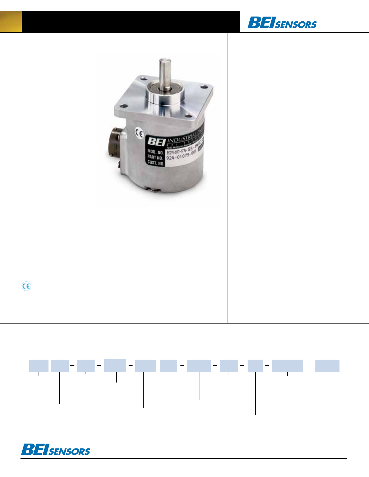
H25X Absolute Optical Encoder
The H25X series single turn encoder is
designed for those applications that
require 14 or 15 bits of resolution
in a compact, easy-to-integrate
package. Gray Code and Natural
Binary outputs are available for
installations using a parallel input
with the controller. For simplic-
ity of data transmission, ease of
cabling and better noise immu-
nity, an SSI (Serial Synchronous
Interface) is also offered. This
encoder works with the BEI Serial-to-
Parallel converter, allowing for system
upgrades from parallel output to SSI.
The H25X is built to the exacting mechanical standards used with the H25 design,
including: dual preloaded ABEC 7 bearings; matched thermal coefficients on critical
components and electronically centered code disks for high accuracy and stability over
a range of environments. Specify the H25X when you need high pointing accuracy and
ruggedness in a 14 or 15 bit absolute encoder for your telescope, antenna, robotics,
material handling or general industrial automation.
The H25 Absolute Encoder is avail able with the following certification:
EN 55011 and EN 61000-6-2
Mechanical Specifications
Shaft Diameter: 3/8”
Shaft Loading: Up to 25 pounds axial and radial
Shaft Runout: 0.0005 T.I.R. at midpoint regardless of shaft diameter
Starting Torque at 25°C: With shaft seal 2.5 in-oz
Bearings: Class ABEC 7 standard, ABEC 5 for 1/2” shaft
Shaft Material: 416 stainless steel
Bearing Housing: Die cast aluminum with iridite finish
Cover: Die cast aluminum
Bearing Life: 2 X 10⁸ revs (1300 hrs at 2500 RPM) at rated load
1 X 10¹⁰ revs (67,000 hrs at 2500 RPM) at 10% of rated load
Maximum RPM: 12,000 RPM mechanical,
Moment of Inertia: 4.1 X 10⁻⁴ oz-in-sec
Weight: 13 oz typical
Connector: MS3112E14-19P, 19–pin connector on encoder body,
mates to MS3116J14-19S (or equivalent)
2
Electrical Specifications
Code: 14 or 15 bits NB or GC
Counts Per Shaft Turn: 16,384 or 32,768
Count Transition Accuracy: ± 1/2 bit maximum
Supply Voltage: 5–28 VDC
Current Requirements: 120 mA typical
Output Formats:
Parallel: Gray Code, Natural Binary
Serial: Serial Synchronous Interface (SSI) compatible
Voltage/Output: (see note 4)
28V/V: Line Driver, 5–28 VDC in, V
28V/5: Line Driver, 5–28 VDC in, V
28V/OC: Open Collector, 5–28 VDC in, OC
SSI: 5–28 VDC IN/5V
Protection Level: Reverse, overvoltage and output short circuit
protection (see note 3)
Frequency Response: 500kHz
Output Termination Pinouts: see Table 1, back page
(see back page)
out
= Vin
out
= 5 VDC
out
out
Environmental Specifications
Enclosure Rating: NEMA 4 & 13 (IP 66) when ordered with shaft seal (on
units with an MS connector) or a cable gland (on units with cable termination).
Temperature: Operating, 0º to 70º C; extended temperature
testing available (see note 7); Storage, -25º to 90º C unless extended
temperature option called out.
Shock: 50 g’s for 11 msec duration
Vibration: 5 to 2000 Hz @ 20 g’s
Humidity: 98% RH without condensation
NOTES & TABLES: All notes and tables referred to in the text can be
found on the back of this page.
H25X Absolute Encoder Ordering Options FOR ASSISTANCE CALL 800-350-2727
Use this diagram, working from left to right to construct your model number (example: H25XD-F4-SS-14GC-28V/V-CW-SM14/19).
All notes and tables referred to can be found on the back of this page.
H25X
TYPE:
Heavy Duty
2.5 inch Dia.
X = Extended
Resolution
HOUSING :
D = Square Flange
E = 2.5 inch dia.
servo mount
These commodities, technology or software if exported from the United States must be in accordance with the Bureau of Industry, and Security, Export Administration regulations. Diversion contrary to U.S law is prohibited.
FACE MOUNTS:
F4 = 6–32 holes,
3 places equally
spaced on
2.00 inch bolt circle
See note 1
SHAFT SEAL
CONFIGURATION:
SS = Shaft Seal
See note 2
NUMBER OF BITS:
14 = 14-Bits, 16,384 counts per turn
15 = 15-Bits, 32,768 counts per turn
Tel: 805-968-0782 /800-350-2727 | Fax: 805-968-3154 / 800-960-2726
7230 Hollister Ave., Goleta, CA 93117-2807 | www.beisensors.com
CODE TYPE:
GC = Gray Code
NB = Natural Binary
VOLTAGE/OUTPUT
28V/V = 5–28V
28V/5 = 5–28V
28V/OC = 5–28V
S3 = Serial Synchronous
Interface (See note 4)
DIRECTION OF COUNT:
CW = Clockwise increasing count
CCW = Counter clockwise
increasing count
in/out
in/5Vout
in/OCout
TERMINATION
LOCATION:
TERMINATION TYPE:
M14/19 = 19 pin connector
CS = Cable with gland seal
Cable length specified in inches
(i.e. C18 = pigtail 18” long)
M18 = MS3102R18-1P
(S3 output only)
OUTPUT
E = End
S = Side
Specification No. 02085-001 Rev.08-11
FEATURES:
S = Special features
specified on purchase
order (consult factory)
See note 5
SPECIAL
Page 2
Serial Synchronous Interface (SSI)
1.38
Ø 2.500
0.100
.100 MIN
Ø 2.275
1.2500
1.2495
0.300
NOTE: SHAFT SEAL NOT
AVAILABLE ON H25 G
2.500
2.498
Ø 2.625
0.125
0.125
Ø
Ø
MS STYLE
1.30 (SM 14/19)
1.38
Ø 2.500
0.100
.100 MIN
Ø 2.275
1.2500
1.2495
0.300
EM CONNECTOR
POSITION
SM CONNECTOR
POSITION
2.50
0.255
0.30
1.2500
1.2495
NOTE: SHAFT SEAL NOT
AVAILABLE ON H25 G
0.3747
0.3745
0.88 ± 0.03
0.34
2.500
2.498
Ø 2.625
0.125
0.125
6-32 UNC-2B
0.250 Min. Deep
3 places equally spaced
on a Ø 2.00 bolt circle.
F4
10-32 UNF-2B
0.188 Min. Deep
3 places equally spaced
on a
Ø 1.875 bolt circle.
F1
Ø
Ø
Ø
30° 30°
Ø 2.500
0.100
Ø 2.275
1.2500
1.2495
0.300
NOTE: SHAFT SEAL NOT
AVAILABLE ON H25 G
2.500
2.498
Ø 2.625
0.125
0.125
10-32 UNF-2B
0.188 Min. Deep
3 places equally spaced
on a Ø 1.875 bolt circle.
F1
Ø
Ø
30°
NOTE: SHAFT SEAL NOT
AVAILABLE ON H25 G
2.500
2.498
Ø 2.625
0.125
0.125
Ø
CONNECTOR*
DATA+A
FUNCTION
YEL
CABLE
1
H40
TERM BOARD
DATA-H
WHT/YEL
7
CLOCK+ B
BLU
2
CLOCK- I
WHT/BLU
8
DIRECTION CONTROL C
ORN
3
ENABLE (OPTIONAL) J
WHT/ORN
9
SUPPLY VOLTAGE (+V)D
RED
4
CIRCUIT COMMON (0V) F
BLK
5
CASE GROUND G
GRN
6
Max. Frequency (KHz)
Cable Length (feet) 50
1800
100
900 500
200
300
300
200
500
100
1000
4
2
1
3
9
6
8
7
5
H38
(XX = cable length in feet, ie. 10 = 10 feet)
Pin C must be pulled to LO (0V)
ONE REVOLUTION
CW Increasing Count Viewing Shaft
ETC. THRU LSB (GO)
SSI output provides effective synchronization
in a closed-loop control system. A clock pulse
train from a controller is used to clock out sensor data: one bit of position data is transmitted
to the controller per one clock pulse received
by the sensor. The use of a differential driver
permits reliable transmission of data over long
distances in environments that may be electrically noisy. The encoder utilizes a clock signal,
provided by the user interface, to time the
data transmission. Receiving electronics must
include an appropriate receiver as well as line
terminating resistors.
Features :
• Synchronous transmission
• Transmission lengths to 1000 feet
• Accepts clock rates from 100 KHz to 1.8 MHz
Data Transmission Sequence
1. Output driver of the encoder is a MAX 491 transceiver in transmit mode. The recommended receiver is
a MAX 491 transceiver in receive mode.
2. Controller provides a series of pulses (or differential pulse pairs) on the CLOCK input lines.
3. On the first HIGH-to-LOW CLOCK transition, the
encoder latches its data at the current position and
prepares to transmit.
4. Controller reads data on the falling edge of the
next 15 clock cycles.
5. The first bit is a START bit and is always HIGH.
6. Next comes 13 data bits beginning with the
most significant bit (MSB) and ending with the parity bit. On 12 bit encoders, bit 13 is LOW. When
parity is not ordered, parity is LOW.
7. After the last CLOCK HIGH-to-LOW transition,
a minimum of 40 microseconds must pass before
the beginning of the next CLOCK series.
Interfacing Long Data Lines
Cable impedance can create a transmission
delay, in effect, shifting the phase relationship
between the clock pulse and the data. If this
phase shift exceeds 180°, then the wrong bit
position will be sampled by the receiver. As a
result, the maximum allowable clock frequency
is a function of the cable length. For 24 AWG,
stranded, 3 pair cable (BEI part number 37048003 or equivalent) the group delay is 1.36ns/ft.
The table below shows the maximum transmission rate allowable as a function of cable length
to ensure a phase shift of less than 90°.
CLOCK, Maximum (kHz) =
92,000 / Cable Length (ft)CW
Cable Length (ft) 50 100 200 300 500 1000
Max Freq (kHz) 1800 900 500 300 200 100
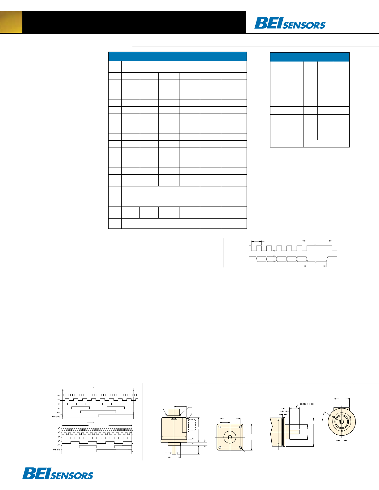
Figures
Figure 1
Gray Code
Figure 2
Natural Binary
H25X Absolute Optical Encoder
2
M14/19
and the compatibility of your receiving electronics with
Line Driver type outputs.
28V/V: Multi-voltage Line Driver (7272*): 100 mA
source/sink. Input voltage 5 to 28 VDC +/- 5% standard
(Note: V
= Vin). This driver is TTL compatible when
out
used with 5 volt supply. Supply lines are protected
against overvoltage to 60 volts and reverse voltage.
Outputs are short circuit protected for one minute.
Supply current is 120 mA typical (plus load current). This
is the recommended replacement for 3904R and 7406R
open collector outputs with internal pullup resistors. It is
also a direct replacement for any 4469, 88C30, 8830 or
26LS31 line driver.
28V/5: Multi-voltage Line Driver (7272*): 100 mA
source/sink. Input voltage 5 to 28 VDC +/- 5% standard, internally regulated with 5V (TTL compatible) logic
out. Supply lines are protected against overvoltage to
60 volts and reverse voltage. Outputs are short circuit
protected for one minute. Supply current is 90 mA typical (plus load current). Note: Limit encoder load to 2.5W
max at ambient. Example at 12 VDC: 2.5W/(+12VDC
minus +5VDC) = 357 mA total allowed current. Consult
factory for your specific requirements.
28V/OC: NPN Open Collector (3904*, 7273*). Current
EM CONNECTOR
POSITION
SM CONNECTOR
POSITION
2.50
0.255
0.30
0.88 ± 0.03
ETC. THRU LSB (GO)
ETC. THRU LSB (20)
CW Increasing Count Viewing Shaft
CW Increasing Count Viewing Shaft
ONE REVOLUTION
ONE REVOLUTION
Gray Code Natural Binary Connector Cable
14 BIT 15 Bit 14 BIT 15 Bit
MSB G
G
G
G
G
G
G
G
G
G
G
G
G
LSB14 G
LSB15 DIR G
CONTROL CONTROL
G14 213 214 A WHT/BLK
13
G13 212 213 B WHT/BRN
12
G12 211 212 C WHT/RED
11
G11 210 211 D WHT/ORN
10
G10 29 210 E WHT/YEL
9
G9 28 29 F WHT/GRN
8
G8 27 28 G WHT/BLU
7
G7 26 27 H WHT/VIO
6
G6 25 26 J WHT/GRY
5
G5 24 25 K WHT
4
G4 23 24 L GRY/BLK
3
G3 22 23 M GRY/BRN
2
G2 21 22 N GRY/RED
1
G1 20 21 P GRY/ORN
0
DIR 20 R *
0
CASE GROUND S GRN
OV (CIRCUIT COMMON) T BLK
LATCH DIR/LATCH LATCH DIR/LATCH U *
+V (SUPPLY +V (SUPPLY +V (SUPPLY +V (SUPPLY V RED
VOLTAGE) VOLTAGE) VOLTAGE) VOLTAGE)
SHIELD DRAIN — BARE
* DIR Control - ORN, LATCH - YEL, 15 bit LSB-GRY/YEL
2
Units Manufactured before April 2007 are LSB Justified
Ordering SSI :
HOW TO SPECIFY SSI OUTPUT IN THE ENCODER MODEL
NUMBER: Use the designation, S3 between the Code Format designation
and the Connector designation. Example: H25D-SS-12GC-S3-CW-SM18
Notes
1. Mounting is usually done either using the D-style square
flange mount, E- or G-style servo mounts, or one of the
standard face mounts, F1 for example. Consult factory for
additional face mount options.
2.The shaft seal is recommended in virtually all installations. The most common exceptions are applications
requiring a very low starting torque or those requiring
operation at both high temperature and high speed.
3. Complementary outputs are recommended for use
with line driver type (source/sink) outputs. When used
with differential receivers, this combination provides a
high degree of noise immunity.
4. Output IC’s: Output IC’s are available as either Line
Driver (LD) or NPN Open Collector (OC) types. Open
Collectors require pull-up resistors, resulting in higher
output source impedance (sink impedance is similar to
that of line drivers). In general, use of a Line Driver style
output is recommended. Line Drivers source or sink current and their lower impedance mean better noise immunity and faster switching times. Warning: Do not connect
any line driver outputs directly to circuit common/OV,
which may damage the driver. Unused outputs should
be isolated and left floating. Our applications specialists
would be pleased to discuss your system requirements
Parallel Code (14 & 15 Bit)
Tel: 805-968-0782 /800-350-2727 | Fax: 805-968-3154 / 800-960-2726 | 7230 Hollister Ave., Goleta, CA 93117-2807
www.beisensors.com
Dimensions
H25XD - Square Flange
1.30 (SM 14/19)
1.2500
Ø
1.2495
Ø 2.52
MAX
MS STYLE
CONNECTOR
0.3747
Ø
0.3745
2.064 TYP
1.032
Direction of Count: Standard is CW increasing when viewed from the
shaft end. Pin R is normally HI (or N/C) and is pulled up internally to +V.
To reverse the count direction, Pin R must be pulled LO (COMMON ).
Latch control: Encoder outputs are active and provide continuous
parallel position information when Pin U is HI (or N/C). Pin U is pulled up
internally to +V. When Pin U is LO (COMMON) the encoder outputs are
latched at the logic state that is present when the latch is applied and
will stay latched until Pin U is no longer grounded.
Dir/Latch on 15-Bit Encoders: Due to a limited number of connector
pins, either direction of count or latch is available on pin U. Direction
standard of latch specified as -S special.
M18 Connector is a MS3102R18-1P, 10-pin connector on the
encoder body and mates to an MS3106F18-1S connector or can be
used with a standard cable/connector assembly, BEI P/N 924-3118618XX (Where XX = 10, 20 30 or 50 for a 10, 20, 30, or 50 foot length).
This is the preferred connector for SSI output.
M14/19 Connector is a MS3112E14-19P, 19-pin connector on the
encoder body and mates to an MS3116J14-19S or equivalent.
SSI Timing
CLOCK+
DATA+
START
20us Max
1212 13 14 15
MSB MSB-1 LSB12 LSB13
BIT
H25XE - 2.50 Servo Mount
0.21 R
SQUARE
Ø 0.218 4 HOLES
(Ø 2.919 B.C. REF)
.100 MIN
2.650
SSI Output Termination Table
M18
M14/19
Cable
Conn
START OF
NEXT CLOCK
START
BIT
30°
F4
6-32 UNC-2B
0.250 Min. Deep
3 places equally spaced
on a Ø 2.00 bolt circle.
Conn
1.38
Conn
DATA + A A YEL
DATA- H B WHT/YEL
CLOCK+ B C BLU
CLOCK- I D WHT/BLU
DIR CONTROL C R ORN
CASE GROUND G S GRN
CIRCUIT COMMON F T BLK
+V SUPPLY VOLTAGE D V RED
SHIELD DRAIN — — BARE
40us Min
Parity
(Optional)
30us Min
sink of 80 mA max. Current sourced by external pullup resistor. Output can be pulled up to voltage other
than supply voltage (30 V max). Input voltage 5 to 28
+
VDC
/- 5% standard. Supply current is 120 mA typical. This replaces prior IC’s with designations of 3904,
7406, 3302, 681 and 689.
5. Special –S at the end of the model number is used to
define a variety of non-standard features such as special
shaft lengths, voltage options, or special testing. Please
consult the factory to discuss your special requirements.
6. Higher frequency response may be available. Please
consult with the factory.
7. Extended temperature ratings are available in the following ranges: -40 to 70°C, -40 to 85°C, –20 to 105°C and
–40 to 105°C depending on the particular model. Extended
temperature ranges can affect other performance factors.
Consult with factory for more specific information.
8. Mating straight plug receptacles may be ordered from
the factory: For M14/19 use MS3116J14-19S,
For M16 use MS3106F16S-1S
For standard pinouts, refer to the facing page.
* Products manufactured prior to April 2007 used the line driver IC number instead of voltage
output in model number.
0.300
0.100
Ø 2.500
1.2500
Ø
1.2495
Ø 2.275
0.34
 Loading...