

Page 1
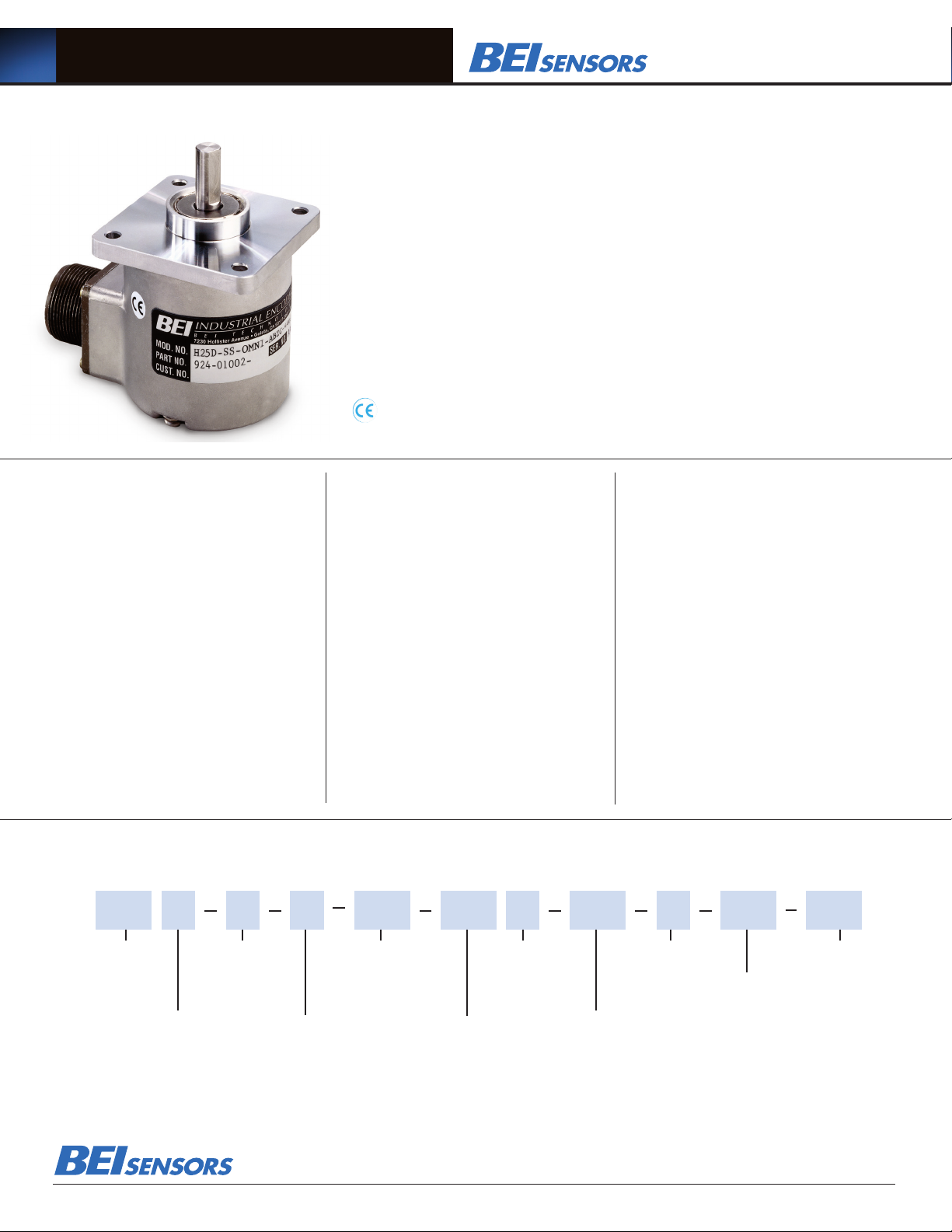
Omnicoder® Model H25®
The Omnicoder features a patented dynamic encoder resolution capability that allows users to easily
program the encoder resolution to any value between 1 and 10,000 counts per turn. Packaged in
BEI’s flagship Model H25® incremental encoder, the Omnicoder allows for virtually unlimited resolution
variations.
Using the simple programming interface software and USB interface cable, users can program
the encoder resolution on site as needed. In the software, type the encoder resolution and click
‘Program’. A new resolution is now programmed. It’s that easy!
With the Omnicoder, resolution can be programmed and reprogrammed at any time by the user.
For users with multiple resolution requirements, Omnicoders can be kept in stock and programmed
as needed.
The Omnicoder Model H25 Incremental Encoder is available with the following certification:
EN 55011 and EN 61000-6-2
Mechanical Specifications
Shaft Diameter: 3/8” (1/2”as special feature)
Flat On Shaft: 3/8” Shaft: 0.80 long X 0.03” deep;
1/2” Shaft: 0.80 long X 0.04” deep
Shaft Loading: 3/8” shaft: Up to 40 pounds axial and 35
pounds radial; 1/2” shaft: Up to 90 pounds axial and 80 pounds
radial
Shaft Runout: 0.0005 T.I.R. at midpoint regardless of
shaft diameter
Starting Torque at 25°C: Without shaft seal 1.0 in-oz (max);
With shaft seal 2.5 in-oz (max); 1/2” shaft with shaft seal:
3.5 in-oz (max)
Bearings: Class ABEC 7 standard, ABEC 5 for 1/2” shaft
Shaft Material: 416 stainless steel
Bearing Housing: Die cast aluminum with protective finish;
stainless steel (special feature)
Cover: Die cast aluminum; stainless steel (special feature)
Bearing Life: 2 X 10⁸ revs (1300 hrs at 2500 RPM)
at rated load 1 X 10¹⁰ revs (67,000 hrs at 2500 RPM) at
10% of rated load
Maximum RPM: 12,000 RPM nominal, 8000 RPM with
1/2” shaft (see Frequency Response, below) 30,000 RPM
available on units with 3/8” shaft— consult with factory
Moment of Inertia: 4.1 X 10⁻⁴ oz-in-sec2; 5.2 X 10⁻⁴
oz-in-sec2 with 1/2” shaft
Weight: 13 oz typical, 14.5 oz typical with 1/2” shaft
Electrical Specifications
Code: Incremental
Output Format: 2 channels in quadrature, 1/2 cycle index
gated with negative B channel
Cycles Per Shaft Turn: 1 to 10,000 reprogrammable
resolutions. Place “OMNI” in resolution option box.
Supply Voltage: 5 to 28 VDC available
Current Requirements: 140 mA typical + output load, 290 mA
(max).
Voltage/Output: (see note 5)
28V/V: Line Driver, 5–28 VDC in, V
Protection Level: Reverse, overvoltage and output short circuit
(see note 5)
out
= V
in
Frequency Response: Max RPM of 3,000.
Output Terminations: M18
Note: Consult factory for other electrical options
Environmental Specifications
Enclosure Rating: NEMA 4 & 13 (IP 66) when ordered with
shaft seal (on units with an MS connector) or a cable gland
(on units with cable termination).
Temperature: Operating, 0º to 70º C; extended temperature
testing available (see note 8); Storage, -25º to 90º C unless
extended temperature option called out.
Shock: 50 g’s for 11 msec duration
Vibration: 5 to 2000 Hz @ 20 g’s
Humidity: 98% RH without condensation
NOTES & TABLES: All notes and tables referred to in the text
can be found on the back of this page.
Omnicoder Model H25 Ordering Options for assistance call 800-350-2727
Use this diagram, working from left to right to construct your model number (example: H25D-SS-OMNI-ABZC-28V/V-SM18).
H25
All notes and tables referred to in the text
can be found on the back of this page.
TYPE:
H = Heavy Duty
25 = 2.500” Dia.
HOUSING CONFIG.
LETTER:
D=Square Flange
E=2.50 Dia. Servo Mount
G=2.62 Dia. Servo Mount
See dimensions
These commodities, technology or software if exported from the United States must be in accordance with the Bureau of Industry, and Security, Export Administration regulations. Diversion contrary to U.S law is prohibited.
OPTIONAL
FACE MOUNTS
F1, F2, F3, or F4
Blank = None
See note 1
SHAFT SEAL
CONFIGURATION:
SS = Shaft Seal
(Not avail. on H25G)
Blank = Shielded Bearing
See note 2
Tel: 805-968-0782 /800-350-2727 | Fax: 805-968-3154 / 800-960-2726
7230 Hollister Ave., Goleta, CA 93117-2807 | www.beisensors.com
CYCLES PER TURN:
OMNI = Omnicoder
reprogrammable resolution,
select 1 to 10,000 integer CPT
NO. OF CHANNELS:
ABZ = Dual with Index
COMPLEMENTS
C = Complementary
Outputs
VOLTAGE/OUTPUT:
28V/V = 5–28V
OUTPUT TERMINATION
in/out
See note 3
LOCATION:
S = Side
OUTPUT
TERMINATION:
M18 =MS3102R18-1P
See table 1 & note 6
Specification No.02126-001 Rev. 02-14
SPECIAL
FEATURES:
S = Special
specified on
purchase
features
order
(consult
factory)
See
note 4
Page 2

Omnicoder® Model H25®
30°
10-32 UNF-2B
0.188 Min. Deep
3 places equally spaced
on a Ø 1.875 bolt circle.
4-40 UNC-2B
0.250 Min. Deep
4 places equally spaced
on a Ø 2.00 bolt circle.
F1
4-40 UNC-2B
0.250 Min. Deep
4 places equally spaced
on a Ø 1.272 bolt circle.
(0.900 square, Ref.)
45°
F2
F3
For Reference: Old Color of Drawings:
30°
10-32 UNF-2B
0.188 Min. Deep
3 places equally spaced
on a Ø 1.875 bolt circle.
F1
4-40 UNC-2B
0.250 Min. Deep
4 places equally spaced
on a Ø 1.272 bolt circle.
(0.900 square, Ref.)
45°
F2
For Reference: Old Color of Drawings:
For Reference: Old Color of Drawings:
1.38
0.34
30°
10-32 UNF-2B
0.188 Min. Deep
3 places equally spaced
on a Ø 1.875 bolt circle.
4-40 UNC-2B
0.250 Min. Deep
4 places equally spaced
on a Ø 1.272 bolt circle.
(0.900 square, Ref.)
4-40 UNC-2B
0.250 Min. Deep
4 places equally spaced
on a Ø 2.00 bolt circle.
45°
F1
F2 (H25G Only)
4-40 UNC-2B
0.250 Min. Deep
4 places equally spaced
on a Ø 1.272 bolt circle.
(0.900 square, Ref.)
45°
F2
F3
For Reference: Old Color of Drawings:
0.88 ± 0.03
1.38
Ø 2.500
0.100
.100 MIN
Ø 2.275
1.2500
1.2495
0.300
NOTE: SHAFT SEAL NOT
AVAILABLE ON H25G
0.34
30°
10-32 UNF-2B
0.188 Min. Deep
3 places equally spaced
on a Ø 1.875 bolt circle.
4-40 UNC-2B
0.250 Min. Deep
4 places equally spaced
on a Ø 1.272 bolt circle.
(0.900 square, Ref.)
4-40 UNC-2B
0.250 Min. Deep
4 places equally spaced
on a Ø 2.00 bolt circle.
45°
F1
F2 (H25G Only)
4-40 UNC-2B
0.250 Min. Deep
4 places equally spaced
on a Ø 1.272 bolt circle.
(0.900 square, Ref.)
45°
F2
F3
Ø
For Reference: Old Color of Drawings:
30°
10-32 UNF-2B
0.188 Min. Deep
3 places equally spaced
on a Ø 1.875 bolt circle.
45°
F1
45°
For Reference: Old Color of Drawings:
0.88 ± 0.03
1.38
Ø 2.500
0.100
.100 MIN
Ø 2.275
1.2500
1.2495
0.300
0.34
30°
10-32 UNF-2B
0.188 Min. Deep
3 places equally spaced
on a Ø 1.875 bolt circle.
4-40 UNC-2B
0.250 Min. Deep
45°
F1
F2 (H25G Only)
4-40 UNC-2B
0.250 Min. Deep
4 places equally spaced
45°
F2
Ø
For Reference: Old Color of Drawings:
0.88 ± 0.03
1.38
Ø 2.500
0.100
.100 MIN
Ø 2.275
1.2500
1.2495
0.300
NOTE: SHAFT SEAL NOT
AVAILABLE ON H25G
0.34
2.500
2.498
Ø 2.625
0.125
0.125
0.88 ± 0.03
30°
10-32 UNF-2B
0.188 Min. Deep
3 places equally spaced
on a Ø 1.875 bolt circle.
4-40 UNC-2B
0.250 Min. Deep
4 places equally spaced
on a Ø 1.272 bolt circle.
(0.900 square, Ref.)
4-40 UNC-2B
0.250 Min. Deep
4 places equally spaced
on a Ø 2.00 bolt circle.
45°
F1
F2 (H25G Only)
4-40 UNC-2B
0.250 Min. Deep
4 places equally spaced
on a Ø 1.272 bolt circle.
(0.900 square, Ref.)
45°
F2
F3
MS STYLE
CONNECTOR
1.30 (SM16)
1.65 (SM 18)
EM CONNECTOR
POSITION
SM CONNECTOR
POSITION
2.50
0.255
0.30
Ø 2.52
MAX
1.2500
1.2495
0.3747
0.3745
0.88 ± 0.03
Ø
Ø
Ø
Ø
For Reference: Old Color of Drawings:
0.88 ± 0.03
1.38
Ø 2.500
0.100
.100 MIN
Ø 2.275
1.2500
1.2495
0.300
0.34
0.88 ± 0.03
30°
10-32 UNF-2B
0.188 Min. Deep
3 places equally spaced
on a Ø 1.875 bolt circle.
4-40 UNC-2B
0.250 Min. Deep
4 places equally spaced
on a Ø 1.272 bolt circle.
(0.900 square, Ref.)
45°
F1
F2 (H25G Only)
4-40 UNC-2B
0.250 Min. Deep
4 places equally spaced
on a Ø 1.272 bolt circle.
(0.900 square, Ref.)
45°
F2
1.30 (SM16)
1.65 (SM 18)
SM CONNECTOR
POSITION
2.50
0.255
0.30
Ø 2.52
MAX
1.2500
1.2495
0.3747
0.3745
0.88 ± 0.03
Ø
Ø
Ø
For Reference: Old Color of Drawings
:
30°
10-32 UNF-2B
0.188 Min. Deep
3 places equally spaced
on a Ø 1.875 bolt circle.
F1
4-40 UNC-2B
0.250 Min. Deep
4 places equally spaced
on a Ø 1.272 bolt circle.
(0.900 square, Ref.)
45°
F2
For Reference: Old Color of Drawings:
Dimensions
H25D - Square Flange H25E - 2.50 Servo Mount
H25G - 2.62 Dia Servo Mount
0.88 ± 0.03
2.064 TYP
1.032
0.21 R
SQUARE
Ø 0.218 4 HOLES
(Ø 2.919 B.C. REF)
2.625
TOLERANCES: .XX = ± 0.01, .XXX = ±0.005
0.125
0.125
2.500
Ø
2.498
Ø 2.625
NOTE: SHAFT SEAL NOT
AVAILABLE ON H25G
Optional Face Mounts
0.34
30°
F1
10-32 UNF-2B
0.188 Min. Deep
3 places equally spaced
on a Ø 1.875 bolt circle.
45°
F2 (H25G Only)
4-40 UNC-2B
0.250 Min. Deep
4 places equally spaced
on a Ø 1.272 bolt circle.
(0.900 square, Ref.)
F3
4-40 UNC-2B
0.250 Min. Deep
4 places equally spaced
on a Ø 2.00 bolt circle.
30°
F4
6-32 UNC-2B
0.250 Min. Deep
3 places equally spaced
on a Ø 2.00 bolt circle.
1.38
Installation and Programming
INSTALLING THE DRIVER AND SOFTWARE
Step 1 Go to www.beisensors.com/downloads to view the download page
Step 2 Click on the “Windows: USB Virtual COM Port Driver” and save the file to your hard drive.
(Omnicoder Programming is currently supported on WIndows only).
Step 3 Unzip the USB driver to a directory on your hard drive
Step 4 Run “setup” to install drivers
Step 5 From the BEI download web page, click on the “Windows: Omnicoder Program” and save the file
to your hard drive
Step 6 Unzip the program to a directory on the hard drive.
Step 7 Run “setup” to install the Omnicoder Programming software.
Step 8 The program should start automatically. You have finished installing the software and are
now ready to program your Omnicoder. (All Omnicoders are shipped pre-programmed for 1024 CPT).
Below is a screen shot of the program interface.
PROGRAMMING THE OMNICODER
Step 9 Using the Omnicoder programming cable, plug the USB connector end into your PC.
The red X (No cable detected) should change to a green check mark, indicating that the
USB Programming Module was detected. (This may take up to 15 seconds)
Step 10 Plug the M18 connector end into the Omnicoder unit. The red X (No encoder detected)
should change to a green check mark, and the current Omnicoder resolution will be
displayed on your computer screen.
Step 11 To change the Omnicoder resolution, enter a new resolution as an integer between 1 and 10000 in the
box labeled “Program New Resolution.” Then click the “Program” button. In a few seconds, the
new resolution will be uploaded to the Omnicoder. The Omnicoder is now programmed and can be
disconnected. To program a new resolution, repeat Steps 9-11.
Tel: 805-968-0782 /800-350-2727 | Fax: 805-968-3154 / 800-960-2726
7230 Hollister Ave., Goleta, CA 93117-2807 | www.beisensors.com
Figure 1
Output Waveform
1 CYCLE
90 Deg.
A
B
Z
A
B
Z
CCW Rotation Viewing Shaft
Table 1
Incremental Output Terminations
M18 CONNECTOR
PIN CHANNEL
A A
B B
C Z
D +V
E —
F 0V
G CG
H A
I B
J Z
Notes
1. Mounting is usually done either using the D-style square flange mount,
E- or G-style servo mounts, or one of the standard face mounts, F1 for
example. Consult factory for additional face mount options.
2.The shaft seal is recommended in virtually all installations. The most
common exceptions are applications requiring a very low starting torque
or those requiring operation at both high temperature and high speed.
3. Output IC’s: Output IC’s are available as either Line Driver (LD) or
NPN Open Collector (OC) types. Open Collectors require pull-up resistors, resulting in higher output source impedance (sink impedance
is similar to that of line drivers). In general, use of a Line Driver style
output is recommended. Line Drivers source or sink current and their
lower impedance mean better noise immunity and faster switching
times. Warning: Do not connect any line driver outputs directly to
circuit common/OV, which may damage the driver. Unused outputs
should be isolated and left floating. Our applications specialists would
be pleased to discuss your system requirements and the compatibility
of your receiving electronics with Line Driver type outputs.
28V/V: Multi-voltage Line Driver (7272): 100 mA source/sink. Input
voltage 5 to 28 VDC +/- 5% standard (Note: V
TTL compatible when used with 5 volt supply. Supply lines are protected
against overvoltage to 60 volts and reverse voltage. Outputs are short circuit protected for one minute. Supply current is 120 mA typical (plus load
current). This is the recommended replacement for 3904R and 7406R
open collector outputs with internal pullup resistors. It is also a direct
replacement for any 4469, 88C30, 8830 or 26LS31 line driver use
4. Special –S at the end of the model number is used to define a variety of
non-standard features such as special shaft lengths, voltage options, or special testing. Please consult the factory to discuss your special requirements.
5. Higher frequency response may be available. Consult factory.
6. Mating straight plug receptacles may be ordered from the factory:
For M18 use MS3106F18-1S
Manufactured under U.S.patent numbers 7,349,821, 6,789,041
7,336,756
Model H25® and Omnicoder® are trademarks of BEI Sensors &
Systems Company.
= Vin). This driver is
out
HI
LO
 Loading...