

ANTI-DITHER MODULE DIN RAIL MOUNT
WHY USE AN ANTI-DITHER MODULE ?
CASE 1 – STARTS AND STOPS
In certain applications, such as conveyor systems or
web processes it may be necessary to stop the line
to clear a jam or reset the process. There is no way
to control where the encoder is in its output cycle
when this occurs: it may have stopped at the rising or
falling edge (a transition) of an output channel or
somewhere in between. When it stops on a
transition, there can be ambiguity in the controller.
HOW IT WORKS:
This interface module uses the
position information in a dual
channel quadrature encoder to
remove spurious counts caused
by mechanical vibration. Logic
gates in the Anti-Dither Module
use the quadrature relationship to
discriminate between dithering
and actual movement. The
resulting output is a phase-shifted
quadrature signal with ± 1/4 cycle
of hysteresis. The index pulse
from the encoder is optically
isolated and passed directly to the
controller for use as a reference.
The output of the encoder may dither from its HI state
to its LO state due to mechanical noise in the
conveying system. This fluctuation can be read as
true motion in the controller. The Anti-Dither Module
creates hysteresis so mechanical dithering does not
create a false count.
CASE 2 – HIGH VIBRATION
Another situation arises where the end use involves
very high vibration -- construction machinery or mill
duty applications for example. This is especially true
when the encoder is being used as a single channel
tachometer. In this instance the encoder output can
have a vibration signal superimposed on the data
channel, leading to multiple transitions on every
cycle. This effect can be eliminated in the controller
if the encoder has dual channels in quadrature,
however that is not always an option. In this case,
the Anti-Dither module can clean things up
t c
Specification No.02125-003 Rev0611
Note: Refer to BEI Opto Isolator Module Applications guide
for mechanical specifications and connection instructions.
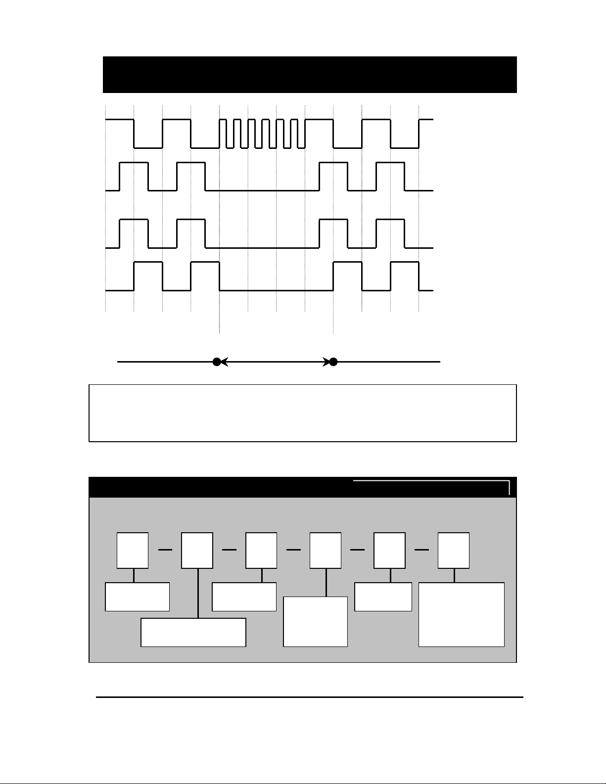
WAVEFORM DIAGRAM
ILLUSTRATING OPERATION OF THE ANTI-DITHER FUNCTION
Mechanical system stop
-- Or -- vibration imposed
Dither or vibration – could
produce error in controller
Mechanical system restart
-- Or-- vibration removed
ENCODER
OUTPUTS
A CHANNEL
B CHANNEL
OUTPUT FROM ANTI-
DITHER MODULE
A’ CHANNEL
B’ CHANNEL
Note: For simplicity of illustration, the inverted channels, A/ and B/ have not been shown.
The index, or Z, channel is also not shown in the above diagram but is passed through directly
as an optically isolated signal and maintains its original relationship to the encoder output
channel.
Anti-Dither Module Order Options
Use this diagram, working from left to right to construct your model number:
Example: EM-DR1-AD-24-TB-28V/V
EM AD DR1 24 TB 28V/V
EM = Electronic
Module
DR1 = 114.5mm X 99mm X
22.5mm DIN Rail Package
AD = Anti-Dither
Function
Output from
Encoder
5 = 5VDC
15 = 12-15 VDC
24 = 24VDC
TB = Terminal
Block
Supply Voltage/Output
from AD Module
28V/V: V
28V/5: V
28V/OC: Vout = Open
Collector
= Vin
out
= 5 VDC
out
Specification No. 02125-003 Rev0611
 Loading...