

Page 1
869610-9
Torque Trak 20K
Torque Telemetry System
User’s Guide
Page 2

Page 3

This document is subject to change without prior notification.
Binsfeld Engineering Inc. | 231-334-4383 www.binsfeld.com 869610-9_A2 Pg. 1
Contents
1 System Overview...........................................................3
1.1 TX20K Transmitter...................................................4
1.2 RX20K Receiver ......................................................4
2 Features and Controls ...................................................5
2.1 RX20K Receiver ......................................................6
2.1.1 Connections ......................................................6
2.1.2 LED Indicators...................................................7
2.2 TX20 Transmitter.....................................................9
2.2.1 External Connections ........................................9
2.2.2 LED Indicator...................................................10
2.2.3 Measurement Ranges.....................................10
2.2.4 Internal Shunt Resistors..................................11
2.2.5 Operating Modes.............................................11
2.2.6 Signal Accuracy...............................................13
2.2.7 Signal to Noise Ratio.......................................14
2.2.8 RF Power Level...............................................14
2.2.9 Power Supply Voltage Measurement ..............14
2.2.10 Power Consumption.....................................15
2.2.11 Battery Life...................................................15
3 Product Safety .............................................................16
4 Installation....................................................................16
4.1 Field Testing ..........................................................17
4.2 Bench Testing........................................................19
5 Communications Protocol............................................19
5.1 General USB Host to RX20K Communications .....19
5.2 RX20K to USB Host Block Messages....................20
5.3 USB Host to RX20K Commands ...........................28
Appendix A: System Specifications....................................36
Appendix B: Calibration Calculations .................................37
Torque on Round Shafts .................................................38
Appendix C: Strain Gage Installation .................................44
Warranty and Service Information.......................................49
FCC Rules Part 15: Computing Devices.............................50
Page 4

This document is subject to change without prior notification.
Binsfeld Engineering Inc. | 231-334-4383 www.binsfeld.com 869610-9_A2 Pg. 2
Page 5

This document is subject to change without prior notification.
Binsfeld Engineering Inc. | 231-334-4383 www.binsfeld.com 869610-9_A2 Pg. 3
1 System Overview
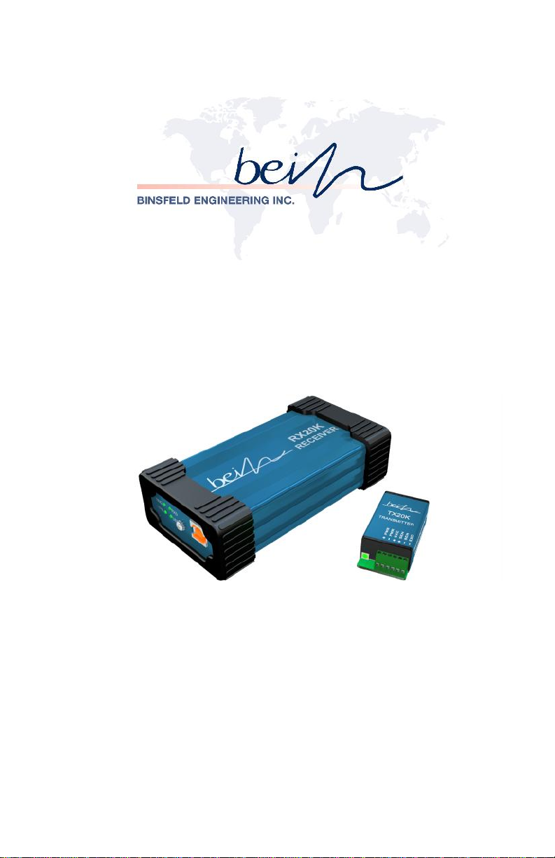
The TorqueTrak 20K Torque Telemetry System utilizes proven digital RF
technology to transmit a single data signal (most typically from a strain
gage) a distance of 10 feet (3 meters) or more depending on the
environment. Up to 16 systems can operate simultaneously on
independent channels.
TX20K Transmitter:
The TorqueTrak 20K is a robust, precision strain measurement
instrument ideal for short-term data collection and diagnostic testing. It is
designed to withstand harsh field conditions with ease-of-use in mind. A
standard TorqueTrak 20K Torque Telemetry System includes the
following items:
TX20K Transmitter
RX20K Receiver
Receiver Antenna Element
Receiver Antenna Magnetic Base with 13-ft Cable
6-ft USB 2.0 A-male to B-male Shielded Cable
10-ft 4-Conductor Ribbon Cable
BS900 Bridge Simulator
Narrow Blade Screwdriver
9V Battery Connectors (2)
9V Lithium Battery
1 Roll of 1” Fiberglass Reinforced Strapping Tape
Butyl Rubber Sheet
Teflon Film kit
Printable TT20K User's documentation
TT20K Equipment Case
Calibration Certificate
TT20K Configuration and Monitor PC software
Page 6

This document is subject to change without prior notification.
Binsfeld Engineering Inc. | 231-334-4383 www.binsfeld.com 869610-9_A2 Pg. 4
1.1 TX20K Transmitter
High signal-to-noise ratio for excellent resolution
Low temperature coefficient for accuracy from -40 to 85°C
Wide power supply input range from 6 to 20VDC
Power Standby mode to extend battery life
Two on-board shunt calibration values
Status Indicator light to assist in troubleshooting
Circuit fully encapsulated
Two different transmit modes; Block, and Stream.
Remotely configurable sample rate, signal bandwidth, baud rate,
RF channel, transmit power, and input signal range.
Two on-board shunt calibration values.
Status Indicator light to assist in troubleshooting.
Circuit fully encapsulated.
1.2 RX20K Receiver
Compact 30 x 63 x 125 mm (1.2" x 2.5" x 5") size.
USB powered (PC or USB charger)
Digital USB serial data and analog voltage output signals
Stable 1.2KHz analog output frequency response
Configurable RF channel settings
Seven unique simulated transmitter inputs
Configure from PC over USB connection
Standalone operation without PC using analog output
Four external status LEDs.
Analog output configurable for 0-5V, 0-10V, ±3V, ±5V, ±10V.
Configurable analog output offset, scale, and polarity.
Page 7

This document is subject to change without prior notification.
Binsfeld Engineering Inc. | 231-334-4383 www.binsfeld.com 869610-9_A2 Pg. 5
Configurable input for optional speed sensor.
Simple Configuration and Monitor PC software included as well
as serial protocol information for digital interface to data
acquisition systems.
2 Features and Controls
The TT20K is a dynamic torque measurement system designed for
temporary installations. The TX20K Transmitter is mounted on the
rotating shaft along with a strain gage(s) and battery. The RX20K
Receiver is connected to the USB port of a PC. The TX20K and RX20K
communicate with one another using RF transceivers built into each.
The strain gage (torque) signal and status information is transmitted off
the shaft by the TX20K and received by the RX20K and then sent on to
the PC. Operational configuration information is sent from the PC,
though the RX20K to the TX20K on the shaft.
The TT20K system is compact yet powerful. Configuration and
monitoring is intuitive using the included PC software. Incorporation into
data acquisition systems can be accomplished using the serial digital
data available through the USB connection or the standard analog
output.
The RF transceivers in the TX20K and RX20K are user selected to
operate any of 16 different frequencies below. This allows up to 16
TT20K systems to simultaneously operate in fairly close proximity.
These RF frequencies are different than those of the TT10K system. So
TT20K and TT10K systems can also operate in close proximity without
interference.
Table 1, TT20K RF Channels
CH
Freq (MHz)
CH
Freq (MHz)
CH
Freq (MHz)
CH
Freq (MHz)
1
903.37
5
909.37
9
915.37
13
921.37
2
904.87
6
910.87
10
916.87
14
922.87
3
906.37
7
912.37
11
918.37
15
924.37
4
907.87
8
913.87
12
919.87
16
925.87
The TX20K RF transmission power level is user adjustable. There are
four different levels that can be chosen depending on the specific
Page 8
This document is subject to change without prior notification.
Binsfeld Engineering Inc. | 231-334-4383 www.binsfeld.com 869610-9_A2 Pg. 6
application. A higher RF power level will allow for more reliable
transmissions over longer distances or in noisy RF environments. The
lower RF power levels will increase battery life longevity.
The RX20K always operates at maximum allowable RF power level
since it is not battery operated.
2.1 RX20K Receiver
The Receiver module had no display or control buttons. Configuration is
done through the USB connection with a PC using the included
Configuration and Monitor software. See the Configuration and Monitor
software User's Guide for information regarding program operation and
use. Once the Receiver module has been configured, it is possible to
use it as a standalone system with power through the USB connector
and the optional analog output expansion board.
2.1.1 Connections
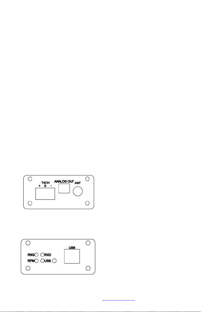
One end of the receiver features a SMA reverse polarity antenna
connector and a 5.08mm pitch 3 position plug receptacle for the optional
speed sensor input. With the standard analog output expansion board, a
3.81mm pitch 2 position plug receptacle provides the analog output
signal.
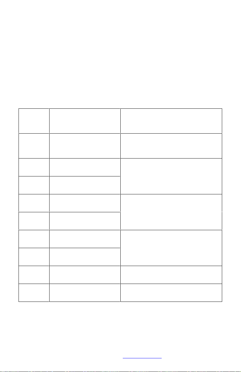
The opposite end has a high insertion force USB type B receptacle for
power and serial communication. Near the USB connector are four
green indicator LEDs.
Page 9

This document is subject to change without prior notification.
Binsfeld Engineering Inc. | 231-334-4383 www.binsfeld.com 869610-9_A2 Pg. 7
2.1.2 LED Indicators
Starting with the upper left LED and moving clockwise, the indicators are
RNG, RXD Data, USB Data, and RPM.
During power-up initialization or after a system reset, the normal LED
pattern has both USB Data and RPM LEDs OFF while RNG and RXD
Data LEDs alternate being ON. The power-up initialization lasts for
about 5 seconds followed by all LEDs being on solid for about 1 second
then all turn OFF before beginning normal operation.
If a bootloader checksum error is detected during initialization, the RXD
Data LED turns ON alone and remains ON (not recoverable).
If a program checksum error is detected during initialization, the RPM
LED turns ON alone and remains ON (not recoverable).
Page 10
This document is subject to change without prior notification.
Binsfeld Engineering Inc. | 231-334-4383 www.binsfeld.com 869610-9_A2 Pg. 8
2.1.2.1 Range (RNG) LED
The Range LED is ON solid green when torque values are being
received from the TX20K and are within range. If no torque values are
being received, the Range LED is OFF. If torque error value(s) are
received, the Range LED flashes at a rate of 2Hz. If errors are received
intermittently, the Range LED is retriggered OFF for a least one
250msec period.
Table 2, Signal Sample Error Values
Torque
sample
value
Description
Indication
±20000
Valid signal sample
value range
Samples between these values
(inclusive) are valid signal
measurements
+20001
TX20K input differential
mode over-range
The input signal is out-of-range.
Increase Range setting, check
gage and wiring
-20001
TX20K input differential
mode under-range
+20002
TX20K input common
mode over-range
+Vsen of the bridge is not near
midscale of Vexc. Check gage
and wiring
-20002
TX20K input common
mode under-range
+20005
TX20K internal analog
zero is over-range
Internal circuit fault
-20005
TX20K internal analog
zero is under-range
+20010
TX20K Vpwr is overrange
Circuit damage could occur.
Check Vpwr (battery) voltage.
-20010
TX20K Vpwr is underrange
Circuit may not function properly.
Check Vpwr (battery) voltage.
Note: Larger error values have higher priority when two or more errors
occur at the same time.
Page 11

This document is subject to change without prior notification.
Binsfeld Engineering Inc. | 231-334-4383 www.binsfeld.com 869610-9_A2 Pg. 9
2.1.2.2 RF Receive Data (RXD) LED
The green RXD Data LED is retriggered ON for 20msec when a byte is
received by the RF transceiver of the RX20K. If the 20msec ON duration
expires before another byte is received, the RXD Data LED switches
OFF until another byte is received.
2.1.2.3 USB Data LED
The green USB Data LED turns ON at the start of a USB Data
transmission from the RX20K to the host PC. The LED remains ON for
20msec after the transmission completes and then turns OFF unless
another transmission begins before the 20msec OFF delay expires.
2.1.2.4 RPM LED
The green RPM LED is triggered ON every time the leading edge of a
speed pulse is detected. After a 20msec duration the RPM LED
switches OFF again unless another speed pulse extends the ON time
another 20msec.
2.2 TX20 Transmitter
The TX20K transmitter is encased in a small, rugged, potted plastic
housing with a six position screw terminal block for external connections.
It also features a single green Status Indicator LED next to its terminal
block.
2.2.1 External Connections
A small six position terminal block provides external connections for
power and strain gauge connections. Because of their small size the
screw terminals can be damaged if too much force is applied. Always
use an appropriately sized small screwdriver and do not over-tighten.
Starting next to the LED indicator the connections are:
+ Transmitter Power
- Transmitter Power
+ Bridge Excitation
+ Bridge Sense
- Bridge Sense
- Bridge Excitation
Page 12

This document is subject to change without prior notification.
Binsfeld Engineering Inc. | 231-334-4383 www.binsfeld.com 869610-9_A2 Pg. 10
2.2.2 LED Indicator
The TX20K has one green indicator LED that is ON solid when it is
operating in any mode other than Standby with no problems detected. In
Standby mode the LED is OFF to conserve battery power.
2.2.2.1 Input Signal Out of Range
When the input (strain gage) signal is detected to be out of range, the
indicator LED flashes five times per second (5Hz).
2.2.2.2 Low Battery Indication
Below approximately 6.0V the TX20K will flash once per second (1Hz
mostly on) its LED indicator and set the Low Battery Warning transmitter
status flag. This indicates a low battery that should be replaced soon.
The TX20K will continue to transmit accurate signal samples until the
battery voltage is below about 4.5V. At this point the LED will flash once
per second (1Hz mostly off), the Low Battery Fault transmitter status flag
will be set and the transmitted samples will have a value of -20010.
2.2.3 Measurement Ranges
The internal amplifier of the TX20K has seven configurable range
settings of 0.2, 0.5, 1, 2, 5, 10, and 20mV/V.
TX20K bridge excitation voltage is 3.0V. The unitless full scale digital
output value for all ranges is ±20,000.
Page 13
This document is subject to change without prior notification.
Binsfeld Engineering Inc. | 231-334-4383 www.binsfeld.com 869610-9_A2 Pg. 11
The TX20K has seven user selectable input range settings from ±0.2 to
±20mV/V. The table below shows just the positive side. The transmitted
signal sample has a maximum range of ±20000. This gives the output
resolutions listed below for each range.
Table 3, Input Ranges
Input
Range
mV/V
1
Input
Range
µe
2
Output
Resolution
µe/lsb
2
Output
Resolution
µV/V/lsb
Output
Shunt1
3
100µV/V
Output
Shunt2
3
1mV/V
0.2
100
0.005
0.010
10000
over-range
0.5
250
0.0125
0.025
4000
over-range
1
500
0.025
0.050
2000
20000
4
2
1000
0.05
0.10
1000
10000
5
2500
0.125
0.25
400
4000
10
5000
0.25
0.5
200
2000
20
10000
0.51100
1000
1
These are the absolute maximum input values (±). If the expected input levels are close
to these, the next larger input range should be selected. This will give some overhead for
the signal span and gage offset.
2
Microstrain with a Gage factor = 2.00.
lsb = least significant bit of the output (transmitted) sample value.
3
The shunt values shown are for a 350
Ω gage
4
This shunt value is right at full scale and could cause an over-range condition
2.2.4 Internal Shunt Resistors
There are two internal shunt resistors for calibration that can be enabled
and disabled individually by the RX20K.
Shunt 1 is 875KΩ, 0.1%, 10ppm to produce Vout = 100µV/V with a 350Ω
bridge.
Shunt 2 is 87370Ω, 0.1%, 10ppm to produce Vout = 1mV/V with a 350Ω
bridge.
2.2.5 Operating Modes
2.2.5.1 Block Mode
In Block mode torque measurements are buffered and transmitted to the
RX20K in blocks of 100 samples at regular intervals. Immediately after
Page 14
This document is subject to change without prior notification.
Binsfeld Engineering Inc. | 231-334-4383 www.binsfeld.com 869610-9_A2 Pg. 12
each block is transmitted, the TX20K switches its transceiver to receive
configuration commands from the RX20K. If a command is received
before the next block needs to be sent, it is executed. If no command is
received, the next sample block is transmitted at the scheduled interval.
The TX20K always operates in this mode when it powers up.
Because samples are buffered at the transmitter in block mode, they are
delayed by between one and two block intervals before reaching the
USB port of the PC.
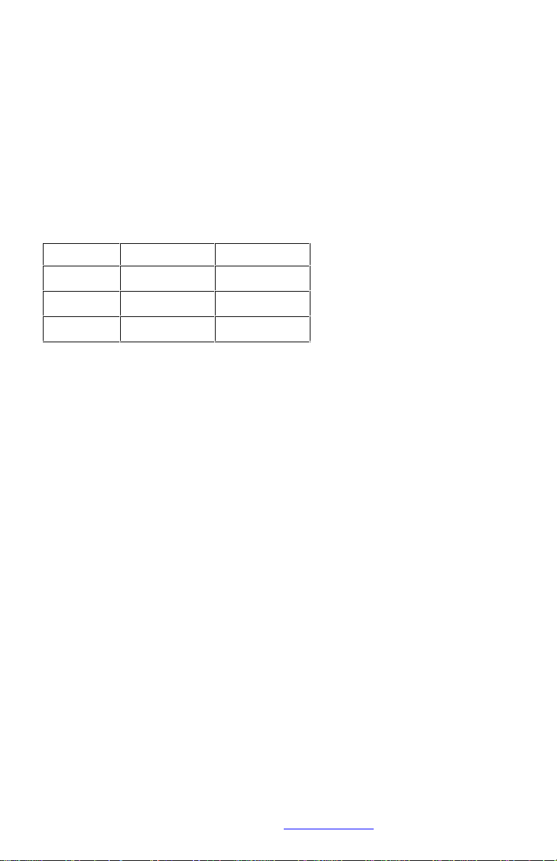
Table 4, Block mode baud/sample rates
Baud Rate
Sample Rate
Block Interval
250Kbps
5000sps
20msec
250Kbps
500sps
200msec
250Kbps
50sps
2 seconds
2.2.5.2 Stream Mode
In Steam Mode the transmitter streams torque measurements
individually and continuously at a rate of 5000 samples per second.
Samples reach the analog output with low latency. This is the highest
speed, lowest latency operating mode for the TT20K. This makes it very
useful for accurately synchronizing the torque signal to other events or
signals.
Since the TX20K is constantly transmitting torque samples, it does not
have enough time to switch its transceiver to receive commands from the
RX20K. Therefore, the operational mode of the TX20K cannot be
changed while it is in Stream Mode. However, the user can specify how
long the TX20K will be in Stream Mode. This time can be from 1 to 4095
minutes (2 days, 20 hours, 15 minutes) or indefinite, which is when the
battery dies or power is cycled. When Stream Mode time expires, the
TX20K reverts back to Block Mode operation at 250Kbaud/5000sps.
Cycling TX20K power takes it out of Stream Mode and back into Block
Mode operation.
In Stream mode, samples are also buffered and transmitted serially
through the USB connection in 100 sample blocks just like block mode.
Page 15
This document is subject to change without prior notification.
Binsfeld Engineering Inc. | 231-334-4383 www.binsfeld.com 869610-9_A2 Pg. 13
2.2.5.3 Standby Mode
This is the TX20K low power, sleep mode. It is used to conserve battery
power between test sessions. No torque or status data is transmitted
while in Standby Mode. The TX20K wakes from this mode every 15
seconds to see if the RX20K is sending Wake commands. If not, the
TX20K goes back to sleep. If the TX20K receives a Wake command
from the RX20K, it will wake and operate at same Block Mode
baud/sample rate as when it was put to sleep. Resetting power of the
TX20K will take it out of Standby Mode and back into Block Mode
operation.
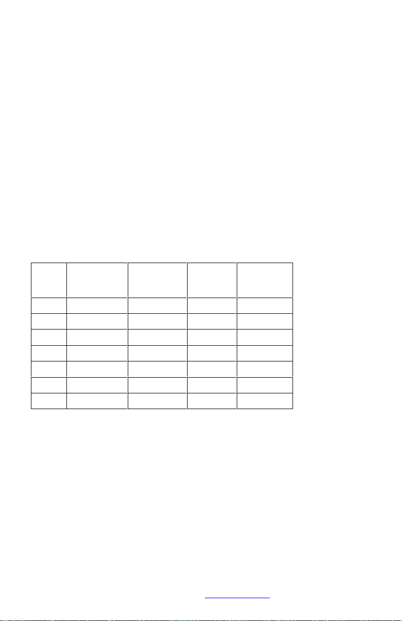
2.2.6 Signal Accuracy
Below are the TX20K’s maximum signal errors at 25
˚C along with the
temperature coefficients for each range setting.
Table 5, TX20K signal accuracy
Input
Range
mV/V
Zero Error
% Full Scale
Scale Error
% Reading
Zero TC
ppm/°C
Scale TC
ppm/°C
0.2
0.02
0.255030
0.5
0.02
0.253025
1
0.15
0.202520
2
0.15
0.202020
5
0.15
0.202020
10
0.15
0.202020
20
0.15
0.202020
Page 16
This document is subject to change without prior notification.
Binsfeld Engineering Inc. | 231-334-4383 www.binsfeld.com 869610-9_A2 Pg. 14
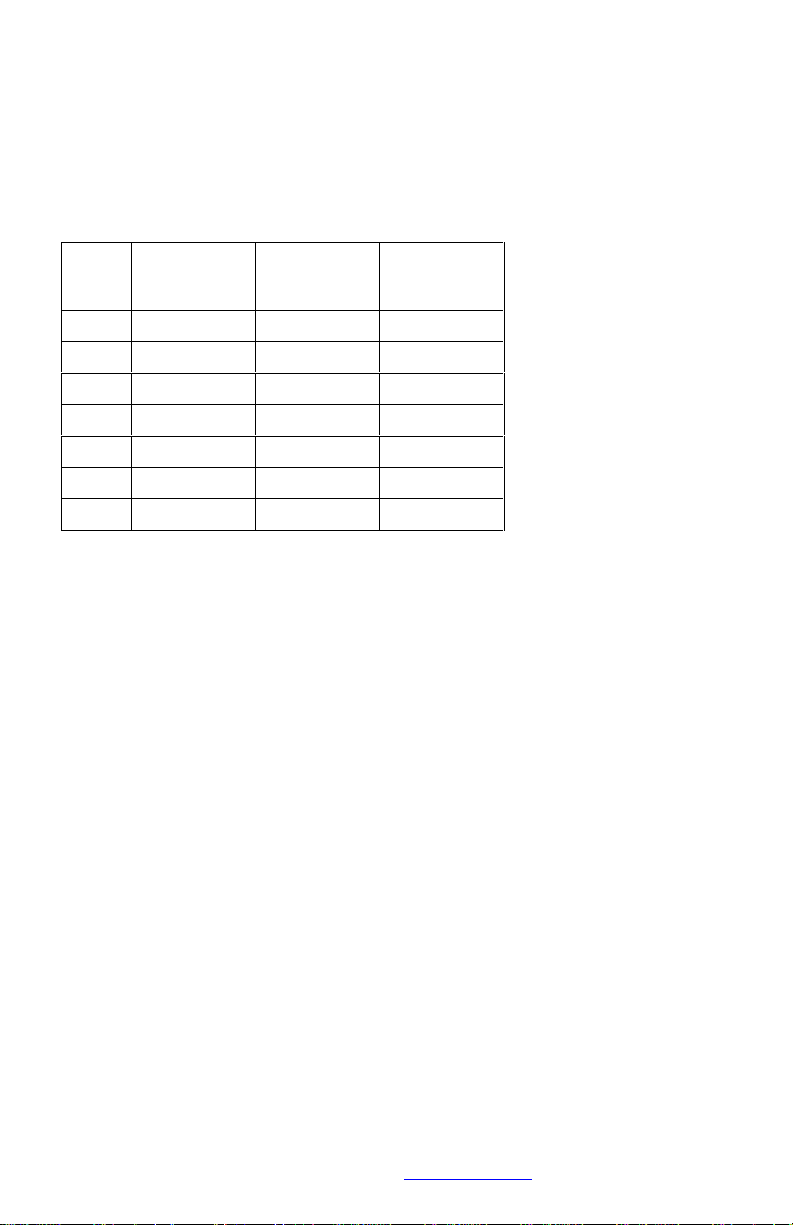
2.2.7 Signal to Noise Ratio
Below are the TX20K’s typical Signal to Noise Ratios at the different
range settings and sample rates.
Table 6, TX20K signal to noise ratios
Input
Range
mV/V
50sps (dB)
500sps (dB)
5000sps (dB)
0.26858
49
0.57566
57
18172
62
28476
66
58679
70
108679
70
208679
70
2.2.8 RF Power Level
The TX20K RF transmission power level is user adjustable. There are
four different levels that can be chosen depending on the specific
application. A higher RF power level will allow for more reliable
transmissions over longer distances or in noisy RF environments. The
lower RF power levels will increase battery life longevity.
2.2.9 Power Supply Voltage Measurement
The TX20K measures and transmits its power supply voltage. The
tolerance of this measurement is +/-2%. The voltage is internally limited
to approximately 15V.
Page 17
This document is subject to change without prior notification.
Binsfeld Engineering Inc. | 231-334-4383 www.binsfeld.com 869610-9_A2 Pg. 15
2.2.10 Power Consumption
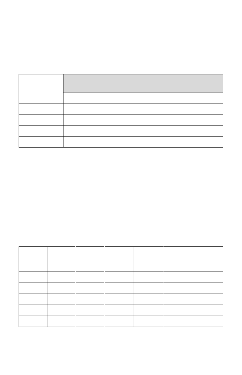
The following table shows typical power supply current draw for the
stream mode.
Table 7, TX20K current draw, stream mode, 250K baud, 5000 sps
Power
Supply (Vdc)
Power supply current draw (mA) at the four RF power
levels
12346.033363943
8.026283033
12.021222426
20.019202122
2.2.11 Battery Life
Below are typical battery life times for the different operating modes of
the TX20K. The 2 batteries listed are an Ultralife 9V Lithium battery and
a standard 9V Alkaline battery. The battery capacities used for the
calculations are 1200mAh for the lithium and 550mAh for the alkaline.
These values are with a 350
Ω gage connected and at and RF Power
level of 1. Actual battery life times can vary depending on battery type,
age, charge state, RF power level, gage resistance and operating
environment.
Table 8, TX20K battery life
Mode
Baud
Sample
Rate
RF
Power
Level
Average
Current
(mA)
Lithium
Battery
(hours)
Alkaline
Battery
(hours)
Stream
250K
5000
12843
20
Block
250K
5000
1264621Block
250K
5001215726
Block
250K
501215726
Standby
250K
5000
1
0.36
3300
1500
Page 18

This document is subject to change without prior notification.
Binsfeld Engineering Inc. | 231-334-4383 www.binsfeld.com 869610-9_A2 Pg. 16
3 Product Safety
WARNING!
PERSONAL INJURY
DO NOT USE this product as a safety or emergency stop device or in
any application where failure of the product could result in personal
injury.
Failure to comply with these instructions could result in death or
serious injury.
The user assumes all risk and liability for the installation and operation of
this equipment. Each application presents its own hazards. Typically,
certain system components are strapped to a rotating shaft. If sufficient
care is not taken to properly secure these components or accessories
connected to them, they can be flung from the shaft, causing damage to
the components or to property or persons in the vicinity. Use more than
enough tape: 10 or more wraps is not too much.
A shield or guard is recommended in applications where something or
someone could come in contact with the rotating parts of the system.
Keep clear of the machinery while the shaft is rotating.
4 Installation
The TorqueTrak 20K System is designed for ease of use. The
procedure for a typical setup on a shaft for obtaining torque
measurements is detailed in the Field Testing section below.
It is recommended that the user bench test the instrument to become
familiar with the various operational features prior to conducting tests in
Page 19

This document is subject to change without prior notification.
Binsfeld Engineering Inc. | 231-334-4383 www.binsfeld.com 869610-9_A2 Pg. 17
the field. The BS900 Bridge Simulator and 9V Battery Connector have
been provided for this purpose. See section 4.2 Bench Testing for
details.
4.1 Field Testing
Although the settings of the TX20K can be changed during operation of
the system, it is best to determine the appropriate Transmitter Gain
setting for a given application prior to installation. Refer to Appendix B
for the relevant calculations.
1. Attach sensor or strain gage to the shaft (or other surface) where
the desired strain will be measured. Refer to Appendix C for
instructions on strain gage application.
2. Secure TX20K and fresh battery to shaft using fiberglass
reinforced strapping tape. Do not cover TX20K Status Indicator.
Alternatively, hose clamps, machined collars, or other mounting
devices may be used but avoid excessive compression.
CAUTION: Be certain all components are fixed firmly to moving
surfaces. The fiberglass reinforced strapping tape should be
wrapped around at least 10 times (5 times in each direction) to
secure the components to the shaft. The open end of the tape
should follow shaft rotation. For extra protection, glue the end of
the tape down. When finished with your testing, cut the tape and
remove the components. Avoid the risk of being struck by an
improperly secured object flung from the machine by standing
clear during operation!
NOTE 1: This method of securing the transmitter and battery
holder is for temporary use only. For long term use this tape
should be examined frequently for the effects of environmental
influences (e.g.: excessive oils) or extreme conditions (e.g.: rapid
starts/stops, high temperatures). Replace tape as required
following the notes in the “CAUTION” previously listed.
NOTE 2: If the shaft is small (
≤1” or 25 mm), balance might be
an issue. In this case, mount the TX20K and battery 180° from
each other on the shaft. The battery weighs nearly the same as
the TX20K.
3. Connect the positive battery terminal to +PWR on TX20K and
the negative battery terminal to -PWR on TX20K. The Status
Indicator light should blink several times and then come on solid.
Page 20

This document is subject to change without prior notification.
Binsfeld Engineering Inc. | 231-334-4383 www.binsfeld.com 869610-9_A2 Pg. 18
Secure to shaft.
NOTE: If testing will not begin for some time, put the TX20K in
Standby mode to save battery life. The Status Indicator light will
turn off. A fresh battery will last for several days in this mode.
4. Cut an appropriate length of 4-conductor ribbon cable (as short
as practical to avoid unwanted electrical noise) and strip and tin
ends. Solder to gage per Appendix C or gage manufacturer’s
specification and make appropriate connections to the TX20K
terminals. Secure loose cable to shaft.
5. Connect Receiver Antenna to Antenna connector on the rear
panel of the RX20K Receiver. Position magnetic-mount antenna
with element installed near the TX20K, typically within 10 feet (3
meters).
6. Use a USB A male to B male cable to connect the RX20K to a
computer for power and communications. The TT20K
Configuration and Monitoring LabVIEW program must already be
installed on the computer as explained in the 818006-9 TT20K
Configuration and Monitoring User's Guide.
NOTE: If the RX20K was previously configured and only the
analog output (no serial data) is being used, any USB power
source with a minimum of 250mA output capability can be used
to power the RX20K.
7. If the TX20K and RX20K are not already communicating, use the
Configuration and Monitoring program to establish
communications between them. Verify adequate signal strength.
If possible, rotate the TX20K through complete range of motion
to verify strong signal reception in all orientations.
8. Use the Configuration and Monitoring program to set up other
parameters as necessary for the desired operation. All
parameters previously configured, should have been
automatically saved to non-volatile memory and should not
require reconfiguration. Configuration and Monitoring program
operation is detailed in document 818006-9.
9. The system is now operational.
Page 21

This document is subject to change without prior notification.
Binsfeld Engineering Inc. | 231-334-4383 www.binsfeld.com 869610-9_A2 Pg. 19
4.2 Bench Testing
1. Connect Receiver Antenna to Antenna connector on the rear
panel of the RX20K Receiver. Position magnetic-mount antenna
with element installed near the TX20K, typically within 10 feet (3
meters).
2. Use a USB A male to B male cable to connect the RX20K to a
computer for power and communications. The TT20K
Configuration and Monitoring LabVIEW program must already be
installed on the computer as explained in the 818006-9 TT20K
Configuration and Monitoring User's Guide.
NOTE: If the RX20K was previously configured and only the
analog output (no serial data) is being used, any USB power
source with a minimum of 250mA output capability can be used
to power the RX20K.
3. Attach 9V Battery Connector to TX20K Transmitter (red to
+PWR, black to –PWR). Attach BS900 Bridge Simulator to the
TX20K terminals +/- EXC and +/- SEN to coincide with pins on
BS900. Clip 9V battery to connector.
4. If the TX20K and RX20K are not already communicating, use the
Configuration and Monitoring program to establish
communications between them. Verify adequate signal strength.
5 Communications Protocol
5.1 General USB Host to RX20K Communications
The RX20K uses a FTDI chips FT230XS USB interface. PC software
drivers are available on the FTDI chips web site
http://www.ftdichip.com/FTDrivers.htm. The Binsfeld Engineering TT20K
Configuration/Monitoring LabVIEW program requires the FTDI VCP
driver for the operating system used (typically Windows 32bit).
Serial communications settings are 1M baud, 8 bits, odd parity, 1 stop
bit, RTS/CTS flow control.
Page 22

This document is subject to change without prior notification.
Binsfeld Engineering Inc. | 231-334-4383 www.binsfeld.com 869610-9_A2 Pg. 20
5.2 RX20K to USB Host Block Messages
Table 9 - RX20K to USB Host Block Message Format
byte
index
byte variable, all
variables start with
USBmsg2host.name.
Description
0
hdr.stx
header start char,
always 0x55
1
hdr.len
# of bytes following
this byte in the USB msg
to the host (always even
and ≥ 52). # of header
bytes is fixed at 44
(not counting stx and
len). # of sample bytes
is normally 200 (100 16
bit samples) but could
be some other even #. #
of TX status bytes is
fixed at 8 and are
always the last 8 bytes
in the message. So len
is normally 44 + 200 + 8
= 252.
Page 23
This document is subject to change without prior notification.
Binsfeld Engineering Inc. | 231-334-4383 www.binsfeld.com 869610-9_A2 Pg. 21
byte
index
byte variable, all
variables start with
USBmsg2host.name.
Description
2
hdr.RXstat (LB)
low byte of the RX20K
status word
b0 - NoTxData, no
data rcvd from TX
b1 - TxDataErr, error
in data rcvd from TX
b2 - CmdAck, valid
cmd rcvd from USB
host
b3 - CmdNak, invalid
cmd rcvd from USB
host
b4 - EcomErr, frame,
parity, or checksum
error in data
received from the USB
host
b5 – Speed input
disabled (sensor pwr
is off)
b6 – not used
b7 - MultXmit, set
for multiple
transmitter
operation; separate
transmitters for each
RF channel (separate
xmit params for each)
3
hdr.RXstat (HB)
high byte of the RX20K
status word
b8 – WakeInPrg, Wakeup sequence in
progress
b14:b9 not used
b15 – TestMode, RX20
is in test mode
operation
Page 24
This document is subject to change without prior notification.
Binsfeld Engineering Inc. | 231-334-4383 www.binsfeld.com 869610-9_A2 Pg. 22
byte
index
byte variable, all
variables start with
USBmsg2host.name.
Description
4
hdr.RFcomm
RF data baud/sps;
0x77: 250K, 5000sps
0x74: 250K, 500sps
(default)
0x71: 250K, 50sps
5
hdr.RFchan
RF data channel index
(ch# - 1), values 0x00
thru 0x0F
6
hdr.RxRFpwr
RX RF xmit power
setting, values 0x00
thru 0x0F
7
hdr.RxRFlevData
RF xcvr receive signal
strength while good data
is being received.
8
hdr.RxRFlevQt
RF xcrv receive signal
strength while the
transmitter is OFF
(quiet or background
noise signal strength).
9
hdr.RxErrRate
# of blocks received
with errors in a sample
of 100 blocks.
10
hdr.unused1
Unused byte
11
hdr.unused2
Unused byte
12
hdr.rpm (LB)
low byte of Speed period
value (shifted 12MHz)
13
hdr.rpm (HB)
high byte of Speed
period value (shifted
12MHz)
14
hdr.rpmRel (LB)
low byte of block start
to Speed input -edge
time
Page 25

This document is subject to change without prior notification.
Binsfeld Engineering Inc. | 231-334-4383 www.binsfeld.com 869610-9_A2 Pg. 23
byte
index
byte variable, all
variables start with
USBmsg2host.name.
Description
15
hdr.rpmRel (HB)
high byte of block start
to Speed input -edge
time
16
hdr.spdShift
Timer #right bit shift
for Speed and Sync
values.
The upper nibble is the
#bit shift for Sync.
The lower nibble is the
#bit shift for Speed.
17
hdr.seqID
8 bit running value that
increments every msg.
18
hdr.opMode
Block = 0, Stream = 1,
Standby = 2
19
hdr.inSrc
RX input source
0 - transmitter
(default)
1 - forced output value
= +1/4FS
2 - forced output value
= +1/2FS
3 - forced output value
= +FS
4 - forced output value
= 0
5 - forced output value
= -1/4FS
6 - forced output value
= -1/2FS
7 - forced output value
= -FS
Page 26
This document is subject to change without prior notification.
Binsfeld Engineering Inc. | 231-334-4383 www.binsfeld.com 869610-9_A2 Pg. 24
byte
index
byte variable, all
variables start with
USBmsg2host.name.
Description
20
hdr.exp[0]
Expansion board type:
0x7f = none
b7 – update expansion
board configuration,
flag
This flag is used
internally and always
displays as '0'.
See separate expansion
board parameter tables
for details of
hdr.exp[0] through
hdr.exp[7]
21
hdr.exp[1]
Expansion board
configuration bits that
control hardware
options. Changing this
bytes triggers expansion
board hardware
configuration to change.
...
Expansion board
parameters
27
hdr.exp[7]
Last expansion board
parameter
28
hdr.rfu[0]
reserved future use, not
presently used
...
reserved future use, not
presently used
41
hdr.rfu[13]
reserved future use, not
presently used
42
hdr.Debug0 (LB)
low byte of Debug0
43
hdr.Debug0 (HB)
high byte of Debug0
44
hdr.Debug1 (LB)
low byte of Debug1
Page 27
This document is subject to change without prior notification.
Binsfeld Engineering Inc. | 231-334-4383 www.binsfeld.com 869610-9_A2 Pg. 25
byte
index
byte variable, all
variables start with
USBmsg2host.name.
Description
45
hdr.Debug1 (HB)
high byte of Debug1
46
samp[0] (LB)
sample 0 low byte
47
samp[0] (HB)
sample 0 high byte
(signed 16 bit)
48
samp[1] (LB)
sample 1 low byte
49
samp[1] (HB)
sample 1 high byte
hdr.len
- 10
samp[n-1] (LB)
sample n-1 low byte
hdr.len
- 9
samp[n-1] (HB)
sample n-1 high byte
hdr.len
- 8
samp[n] (LB)
sample n low byte
hdr.len
- 7
samp[n] (HB)
sample n high byte
hdr.len
- 6
TXstat.Vpwr
TX power supply level
hdr.len
- 5
TXstat.VpwrFlags
TX Vpwr status flags:
b4:b0 - unused
b5 - Vpwr too low
flag
b6 - Vpwr getting
low, replace battery
flag
b7 - Vpwr too high
flag
hdr.len
- 4
TXstat.Range
TX range value setting:
b2:b0 - range value
b7:b3 - unused
Page 28

This document is subject to change without prior notification.
Binsfeld Engineering Inc. | 231-334-4383 www.binsfeld.com 869610-9_A2 Pg. 26
byte
index
byte variable, all
variables start with
USBmsg2host.name.
Description
hdr.len
- 3
TXstat.Shunt
b0 is shunt1 status
b1 is shunt2 status
0 = Off, 1 = On
b7:b2 - unused
hdr.len
- 2
TXstat.RFpwr
b3:b0 = Transmitter RF
TX power level setting
b7:b4 - unused
hdr.len
- 1
TXstat.Misc
b0 – bad/unknown command
or parameter received
b1 – CalErr, error
during auto calibration
process
b2 – CalDflt, nonvolatile memory error,
using default
calibration values
b3 – CfgDflt, nonvolatile memory error,
using default
configuration parameters
b7:b4 – unused
hdr.len
TXstat.SPS
b3:b0 – sample rate code
1 = 50 samples/sec
4 = 500 samples/sec
7 = 5000 samples/sec
b7:b4 – low nibble of
Streaming minutes
remaining value
hdr.len
+ 1
TXstat.Stream
High 8 bits of Streaming
minutes remaining value.
Page 29
This document is subject to change without prior notification.
Binsfeld Engineering Inc. | 231-334-4383 www.binsfeld.com 869610-9_A2 Pg. 27
Table 10: Analog Output Expansion Board hdr.exp[ ] parameters
hdr.exp[]
byte
index
name
inside
program
description
[0]
mEXtype
b7 – update expansion board
configuration flag. Always
write to this index after all
other necessary indexes have
been written. When b7 of index
0 is written as a '1', it
triggers the RX20K to process
the data in the 8 expansion
configuration bytes.
0x00 = analog output; write to
0x80 last to trigger config
[1]
mAOcfg
AO configuration bits:
b7:b4 – unused
b3 – reverse output polarity
b2:b0 - analog output voltage:
0b000 - ±10V
0b001 - 0 to 10V
0b010 - ±5V
0b011 - 0 to 5V
0b100 - ±3V
[2]
mAOoffLB
signed offset value normalized
for the 0.2mV/V range, low byte
[3]
mAOoffHB
signed offset value normalized
for the 0.2mV/V range, high
byte
[4]
mAOscale
unsigned scale factor, fixed
point between b6 and b5
Note: When there is no transmitter data available, all samp[ ] data is
absent from the message and all TXstat bytes are 0x00. It is allowable
for the number of samples contained in a message to be any value from
0 to 100. Normally, only values of 0 or 100 are used.
Page 30

This document is subject to change without prior notification.
Binsfeld Engineering Inc. | 231-334-4383 www.binsfeld.com 869610-9_A2 Pg. 28
5.3 USB Host to RX20K Commands
Table 11 - USB host to RX20K Command Format.
Command Description
byte0
cmd
code
byte1
byte2
byte3
chksum
Read checksums
byte 1 – 0x00
Forces bootloader
checksum to be output
in block header bytes
Debug0 and program
checksum to be output
in Debug1
byte 2 not used (0x00)
byte 1 – 0x01
Cancel pending save
of non-volatile
parameters (used
during TX scan)
byte 2 not used (0x00)
0x40
chksum
Page 31
This document is subject to change without prior notification.
Binsfeld Engineering Inc. | 231-334-4383 www.binsfeld.com 869610-9_A2 Pg. 29
Command Description
byte0
cmd
code
byte1
byte2
byte3
chksum
Expansion board configuration
byte 1 - Expansion board
parameter index
byte 2 - Expansion board
parameter value
byte 1 - Index [0] is always the
Expansion board type with a
byte 2 value:
0xff = no expansion
board
0x80 = analog output
Valid index values are 0
through 7. Writing a value for
index 0 with bit 7 of byte 2 set
triggers updating the
expansion board configuration.
Always write to all other
necessary indexes before
triggering an update of
expansion board configuration.
See tables of expansion board
specific parameters for index
values and corresponding byte
2 parameters.
0x50
chksum
Page 32

This document is subject to change without prior notification.
Binsfeld Engineering Inc. | 231-334-4383 www.binsfeld.com 869610-9_A2 Pg. 30
Command Description
byte0
cmd
code
byte1
byte2
byte3
chksum
Speed input configuration
byte1 – Speed input
configuration
b7:b4 - #bits to right
shift sync timer
value.
b3:b0 - #bits to right
shift speed timer
value.
Speed timer measures the period
between negative speed input
edges.
Sync timer measures the time
from the start of the previous
block message to the first
negative speed input edge.
0x60
0x00
chksum
Receiver RF transmit power
control
byte1 - RF power level to
set (0 to 14)
0x61
0x00
chksum
Receiver RF channel control
byte 1 – RF channel to
set (0 to 15)
value = RF channel (1 to
16) – 1,
add 128 to value for
multiple transmitters
(in other words, set bit 7
of byte 1)
0x62
0x00
chksum
Page 33

This document is subject to change without prior notification.
Binsfeld Engineering Inc. | 231-334-4383 www.binsfeld.com 869610-9_A2 Pg. 31
Command Description
byte0
cmd
code
byte1
byte2
byte3
chksum
Receiver Input Source control
byte 1 - Input source
value (0 to 7)
0 - transmitter
(default)
1 - forced output value
= +1/4FS
2 - forced output value
= +1/2FS
3 - forced output value
= +FS
4 - forced output value
= 0
5 - forced output value
= -1/4FS
6 - forced output value
= -1/2FS
7 - forced output value
= -FS
0x65
0x00
chksum
Page 34

This document is subject to change without prior notification.
Binsfeld Engineering Inc. | 231-334-4383 www.binsfeld.com 869610-9_A2 Pg. 32
Command Description
byte0
cmd
code
byte1
byte2
byte3
chksum
Receiver RF communications
byte1 – Operational mode
Block = 0, Stream = 1,
Standby = 2
byte2 – Block and Standby
Mode byte2 is same as
System RF communications
(both RX and TX) below (cmd
code 0x9a)
value baud
samples/sec
0 (0x71) 250K 50
1 (0x74) 250K 500
(default)
2 (0x77) 250K 5000
If already in standby, sending
the standby command with the
same byte2 value starts the
wake process. Sending the
standby command with a new
byte2 value updates the
baud/sps that will be used but
does not start the wake
process.
If the standby wake process is
active, sending the standby
command with any byte2 value
cancels the active process.
byte2 - Stream Mode: ignored
0x6a
chksum
Page 35
This document is subject to change without prior notification.
Binsfeld Engineering Inc. | 231-334-4383 www.binsfeld.com 869610-9_A2 Pg. 33
Command Description
byte0
cmd
code
byte1
byte2
byte3
chksum
System control:
byte1 - RFU
byte2
1 = Reset TT20K
Transmitter
2 = Reset TT20K
System
0x90
0x00
chksum
System RF channel control
byte 1 – RF channel
value to set (0 to 15)
value = RF channel (1 to
16) - 1
0x92
0x00
chksum
Page 36

This document is subject to change without prior notification.
Binsfeld Engineering Inc. | 231-334-4383 www.binsfeld.com 869610-9_A2 Pg. 34
Command Description
byte0
cmd
code
byte1
byte2
byte3
chksum
System RF communications (both RX
and TX)
byte1 – Low nibble:
Operational mode
Block = 0, Stream = 1, Standby
= 2
byte1 upper nibble – Stream mode:
Duration value most significant 4
bits.
Block: set to 0
Standby: set to 0xF
byte2 – Block mode:
value baud samples/sec
0 (0x71) 250K 50
1 (0x74) 250K 500 (dflt)
2 (0x77) 250K 5000
byte2 – Stream mode:
Streaming duration value low 8 bits. A
duration value of 0 means continue
until power loss. Once in Stream
mode, no commands are accepted
until the duration expires or transmitter
power is cycled. The baud rate is
always 250K and sample rate is 5000.
At the termination of Stream mode the
transmitter enters Block mode 25K
baud and 500 sps. Stream mode is
designed to drive optional analog
output circuitry but it also continues to
transmit digital data in block format
over the USB connection.
byte2 – Standby mode:
0xFF = enter Standby mode
0x9a
chksum
Page 37

This document is subject to change without prior notification.
Binsfeld Engineering Inc. | 231-334-4383 www.binsfeld.com 869610-9_A2 Pg. 35
Command Description
byte0
cmd
code
byte1
byte2
byte3
chksum
Transmitter shunt and range
control
byte1 bits, shunt control
b7:b2, not used
b1 – shunt 2, 0 =
OFF, 1 = ON
b0 – shunt 1, 0 =
OFF, 1 = ON
byte2, transmitter range
value (mV/V * 1ue)
1 = 0.2
2 = 0.5
3 = 1
4 = 2
5 = 5
6 = 10
7 = 20
0xa0
chksum
Transmitter RF power control
byte 1 – RF power level
to set (0 to 15)
0xa1
0x00
chksum
Notes:
The chksum value is the low byte of the sum of byte0, 1, and 2.
The CmdAck and CmdNak bits in USBmsg2host.name.hdr.RXstat
serve as an acknowledgement to USB host messages sent to the
RX20K.
The baud rate, sample rate and transmitter range parameters are saved
in non-volatile memory and retained through power loss.
Page 38
This document is subject to change without prior notification.
Binsfeld Engineering Inc. | 231-334-4383 www.binsfeld.com 869610-9_A2 Pg. 36
Appendix A: System Specifications
Description of system specifications.
TX20K Transmitter Specifications
Power input
6.0 ~ 20VDC
Current draw
See section 2.2.10
Antenna
Internal
Operating
temperature range
-40 to +85°C
(Ultralife 9V lithium battery -40 to +60°C)
Size
26w x 16h x 52 lg mm (1.03"w x 0.64"h x 2.03"lg)
Weight
35g
G force
3000Gs
Operating
Frequencies
902 ~ 928MHz band
see RF channels in Table 1
Excitation voltage
3.0V, Precision reference: 0.1%, 20ppm/°C
Excitation current
12.5mA (max)
Gage resistance
240Ω (min)
RX20K Receiver Specifications
Power input
USB powered (5VDC @ 60mA main board only)
Antenna input
connection
SMA
Operating
temperature range
-40 to +75°C
Size
70w x 37h x 134lg mm (2.76”w x 1.46”h x 5.28”lg)
Weight
230g
Operating
Frequencies
902 ~ 928MHz band
see RF channels in Table 1
Digital Output
connection
USB 2.0 Full Speed compatible, type B receptacle,
using FTDI FT230X USB to UART IC @ 1Mbaud, 8
data bits, odd parity, 1 stop bit, RTS/CTS hardware flow
control
Page 39

This document is subject to change without prior notification.
Binsfeld Engineering Inc. | 231-334-4383 www.binsfeld.com 869610-9_A2 Pg. 37
Serial Output Digital
communication
protocol
See paragraph 5 above.
Speed sensor power
4.2V @ up to18mA. Current draw for the speed sensor
adds to the system USB 5V current draw.
Speed sensor signal
input
10K ohm pull-up to 3.3V. Maximum input freq 10KHz
Speed sensor
example
Spectec 0158M-2-2-2-1-5. There are many variations.
www.spectecsensors.com
Analog output board
power
Powered by the RX20K main board from USB 5V.
Adds approximately 70mA plus maximum output load
current.
Analog output ranges
±3, ±5, ±10, 0 to 5, 0 to 10V
Analog output
impedance
325 ohms
Analog output offset
adjustment range
Half of full scale output.
Analog output scale
adjustment range
8 bit fixed point value with 2 bit integer word length.
0.015625 to 3.984375
Appendix B: Calibration Calculations
The equations in this Appendix define the relationship between the input
signal to the TX20K Transmitter (typically from a strain gage) and the
Full Scale output voltage of the TorqueTrak 20K System. The
calculations are based on parameters of the device being measured (e.g.
shaft diameter), sensor parameters (e.g. gage factor) and Transmitter
Gain setting.
Section B1 is specific to torque measurements on round shafts (full
bridge, 4 active arms).
Section B2 applies to axial strain (tension/compression) measurements
on round shafts (full bridge, 2.6 active arms).
Section B3 is for use with a single grid (1/4 bridge).
1 µe is distortion of the shaft surface 1 x 10⁻⁶in/in. For more technical
information regarding the relationship between shear strain and torque,
see the excellent technical article TN-512 published by Vishay.
Page 40
This document is subject to change without prior notification.
Binsfeld Engineering Inc. | 231-334-4383 www.binsfeld.com 869610-9_A2 Pg. 38
Torque on Round Shafts
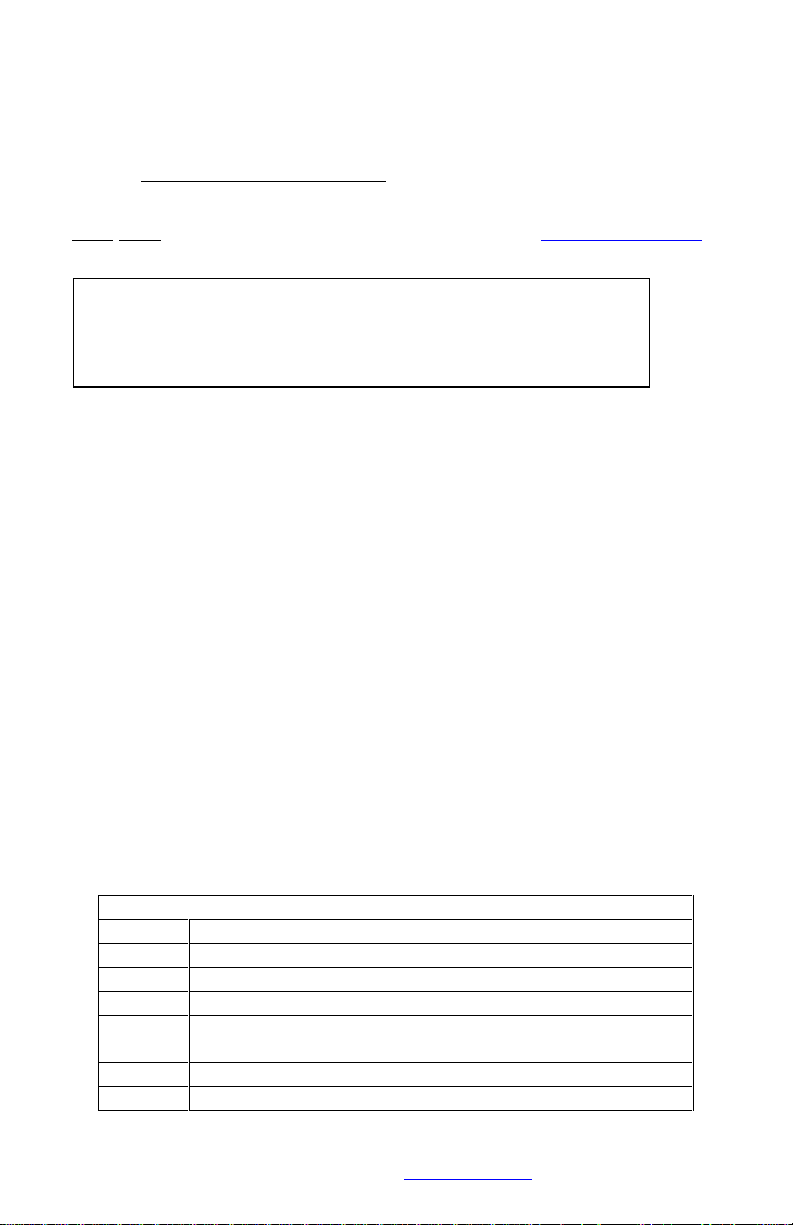
Step 1: Calculate Full Scale Torque, TFS(ft-lb)
The Full Scale Torque corresponds to a system output of 10 V. For a
solid steel shaft, use the calculator on our website at www.binsfeld.com
or use the simplified equation below:
For all other shafts use the more general equation:
For metric applications with Doand Diin millimeters and TFSin N-m, the
general equation is:
Where E= 206.8 x 10³N/mm
2
Legend of Terms
DiShaft Inner Diameter (in) (zero for solid shafts)
DoShaft Outer Diameter (in)
E
Modulus of Elasticity (30 x 106PSI steel)
GF
Gage Factor (specified on strain gage package)
G
XMT
Telemetry Transmitter Gain (user configurable, typical
is 4000 for ±500 microstrain range)
N
Number of Active Gages (4 for torque)
TFSFull Scale Torque (ft-lb)
(VFS)()(E)(4)(D
o
4
-D
i
4
)
───────────────────────── = TFS(ft-lb)
(TX
const
)(GF)(N)(16)(1+)(G
XMT
)(Do)(12)
(1510.38 x 103ft-lb/in3)(D
o
3
)
───────────────── = TFS(ft-lb)
(GF) (G
XMT
)
(VFS)()(E)(4)(D
o
4
-D
i
4
)
───────────────────────── = TFS(N-m)
(TX
const
)(GF)(N)(16000)(1+)(G
XMT
)(Do)
Page 41

This document is subject to change without prior notification.
Binsfeld Engineering Inc. | 231-334-4383 www.binsfeld.com 869610-9_A2 Pg. 39
TX
const
Transmitter constant = 2.5V
VFSFull Scale Output of System = 10 volts
Poisson’s Ratio (0.30 for steel)
Page 42
This document is subject to change without prior notification.
Binsfeld Engineering Inc. | 231-334-4383 www.binsfeld.com 869610-9_A2 Pg. 40
For example, given a solid steel shaft with:
DO(shaft Outer Diameter, measured) = 3.000 inches
GF (Gage Factor from gage package) = 2.08
G
XMT
(TX10K Gain setting) = 4000
so 10 V output from the RX20K indicates 4,901 ft-lb of torque or
490.1 ft-lb/volt.
Step 2: Scale the Full Scale Output
If desired, the Full Scale voltage output of the TX20K can be scaled so
that it corresponds to a convenient torque value, e.g. 100 ft-lb /volt. As
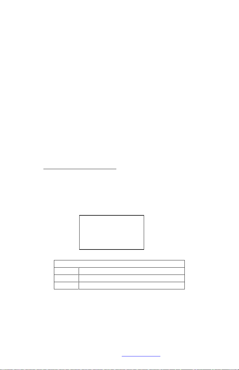
stated earlier, the System Gain can be adjusted from ¼ to 4 times the
Transmitter Gain. The equation below defines the Scale Factor (Z):
Legend of Terms
Z
Scale Factor (0.25 to 4.0)
TFSFull Scale Torque (ft-lb)
T
REF
Reference Full Scale Torque (ft-lb)
In the example from Step 1 above, Full Scale Torque (TFS) has been
calculated to be 4,901 ft-lb. It may be convenient to scale the output so
that 10 V indicates 5,000 ft-lb (1 V = 500.0 ft-lb). First, calculate the
Scale Factor (Z):
(1510.38 x 103ft-lb/in3)(3.000 in)
3
TFS= ────────────────────── = 4,901 ft-lb
(2.08) (4000)
T
FS
Z = ─────
T
REF
Page 43

This document is subject to change without prior notification.
Binsfeld Engineering Inc. | 231-334-4383 www.binsfeld.com 869610-9_A2 Pg. 41
Next, multiply the Scale Factor times the Transmitter Gain setting to find
the System Gain setting.
4000 x 0.9802 = 3920
Scroll to the Gain parameter screen on the RX20K and set the System
Gain to 3920. In summary:
Before adjusting full scale output:
4,901 ft-lb = 10.000 V (490.1 ft-lb/volt)
After adjusting full scale output:
5,000 ft-lb = 10.000 V (500.0 ft-lb/volt)
Step 3: Calibrate the Output
There are two ways to perform a calibration of the installation: a
deadweight calibration or shunt calibration.
Deadweight Calibration
The most precise method is to perform a deadweight calibration. This
involves suspending a known mass a known horizontal distance from the
center of the shaft. This is not always practical but does take into
account all possible deviation in the system (actual material properties
versus data sheet, shaft geometry, gage imbalance, etc.) With the
known moment applied, adjust the System Gain until the output is the
same as the calculated torque value.
Using the parameters outlined in the previous example, a deadweight is
applied to the gaged 3-inch shaft that corresponds to 500 ft-lb of torque.
The System Gain would be adjusted until the output was equal to 1 volt.
NOTE: It is recommended that in order to be meaningful, the deadweight
should create a torque load close to those expected during testing. At a
minimum, they should represent at least 10% of the range.
4,901 ft-lb
─────── = Z = 0.9802
5,000 ft-lb
Page 44
This document is subject to change without prior notification.
Binsfeld Engineering Inc. | 231-334-4383 www.binsfeld.com 869610-9_A2 Pg. 42
Shunt Calibration
The more common method is to perform a shunt calibration. This
method takes into account deviations in the setup from the strain gage to
the transmitter, but unlike a deadweight calibration, none of the
deviations in the physical parameters.
The easiest way to conduct a shunt calibration is by enabling one of the
reference shunt resistors on-board the TX20K. An internal precision
resistor is placed in parallel with one arm of the bridge to simulate a
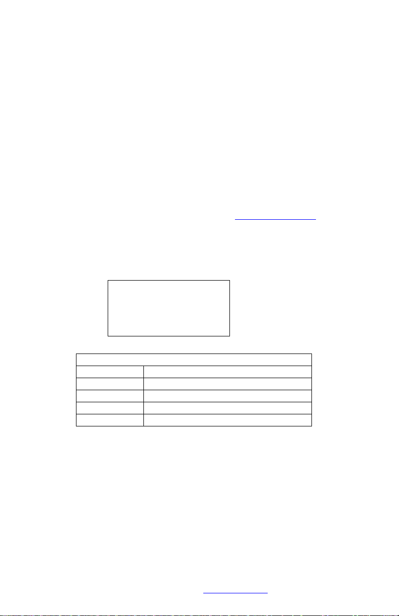
precise strain value. As stated earlier, Reference 1 simulates 100
microstrain (µe) and Reference 2 simulates 500 µe when using a 350
Ω
strain gage with a Gage Factor of 2.0. Alternatively, precision resistors
can be placed in parallel with one arm of the bridge to simulate a torque
load. The Tech Info section on our website (www.binsfeld.com) has a
helpful Torque Strain Calculator to assist in determining the strain a
given resistor value simulates. The equation relating strain and shunt
resistance is shown below:
Legend of Terms
RCShunt Calibration Resistance (kΩ)
RGGage Resistance (Ω)
N
Number of Active Gages
GF
Gage Factor
ε
Strain (µe)
In the example from Steps 1 & 2, the Full Scale Torque is 4,901 ft-lb and
the RX20K output has been scaled so that 10 V corresponds to a torque
load of 5,000 ft-lb by setting the System Gain to 3920. This was
determined by multiplying the Transmitter Gain of 4000 (±500 µe range)
by the Scale Factor (Z) that was calculated to be 0.9802.
First, determine what the system output should be when applying the
shunt resistance. In this case, Reference 1 (100 µe) is a good choice
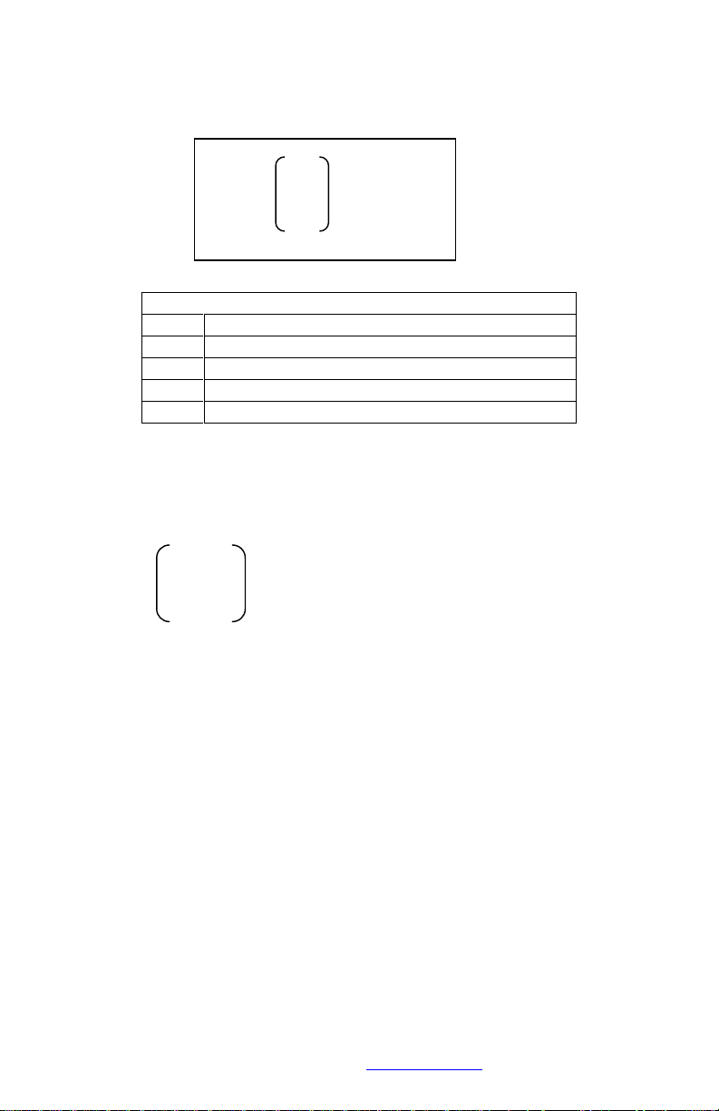
(20% of Full Scale). To calculate the calibrated output of the system,
use the equation below:
R
G
RC= ───────
(N)(GF)(ε)
Page 45
This document is subject to change without prior notification.
Binsfeld Engineering Inc. | 231-334-4383 www.binsfeld.com 869610-9_A2 Pg. 43
Legend of Terms
VSVoltage Output with Shunt Applied (V)
εSStrain Simulated by Shunt (µe, GF = 2.0)
εFSFull Scale Strain (µe, GF = 2.0)
Z
Scale Factor (one if no scaling)
VFSFull Scale Voltage Output (V) (10V)
In this example, with Reference 1 applied, the calibrated Voltage Output
would be calculated as follows:
Adjust the System Gain setting until the output matches this value. The
adjustment is typically small (<0.5%). The system is now ready to
measure torque with the desired output scaling.
NOTE: When the Gage Factor is not 2.0, the actual Full Scale Strain and
Simulated Strain values are affected proportionately. In the example
above with a Gage Factor of 2.08, Full Scale Strain is technically
480.7µe, not 500. However, the Simulated Strain is likewise affected
(Ref 1 becomes 96.14µe, not 100). The ratio of Simulated Strain to Full
Scale Strain remains constant (20%) and the calculation above remains
valid.
Also, if the gage resistance is not 350
Ω, the Reference 1 & 2 Simulated
Strain values are not 100 and 500 µe, respectively. Use our online
calculator or the equation on page 33 to calculate the simulated strain in
this instance (use GF = 2.0).
100 µe
───── (0.9802) (10 V) = VS= 1.9604 V
500 µe
ε
S
VS= ── (Z)(VFS)
ε
FS
Page 46

This document is subject to change without prior notification.
Binsfeld Engineering Inc. | 231-334-4383 www.binsfeld.com 869610-9_A2 Pg. 44
Appendix C: Strain Gage Installation
View BEI’s online Strain Gage Installation Training videos at
www.binsfeld.com/torquetrak/torquetrak-revolution/training-videos.html
(Also refer to instruction bulletin B-127-12 provided with GAK-2-200
Strain Gage Application Kit from Vishay Measurements Group, Inc.,
Raleigh, NC, 919-365-3800, www.measurementsgroup.com.)
PREPARING THE SURFACE
1. A 3-inch square area will be used for gaging. Scrape off any paint
or other coatings and inspect shaft for oil residue. If necessary,
use a degreasing solution or isopropyl alcohol to remove.
2. Rough sand the gaging area with 220 grit paper. Finish the
sanding procedure by wetting the gaging area with M-Prep
Conditioner A and the wetted surface with 400 grit paper
provided. Rinse by squirting with M-Prep Conditioner A. Wipe the
area dry with tissue taking care to wipe in only one direction.
Each time you wipe use a clean area of the tissue to eliminate
contamination.
3. Rinse shaft this time by squirting with M-Prep Neutralizer 5A.
Wipe the gaging area dry with a clean tissue, wiping in only one
direction and using clean area of tissue with each wipe. Do not
allow any solution to dry on the surface as this may leave a
contaminating film which can reduce bonding. Surface is now
prepared for bonding.
MARKING THE SHAFT FOR GAGE ALIGNMENT
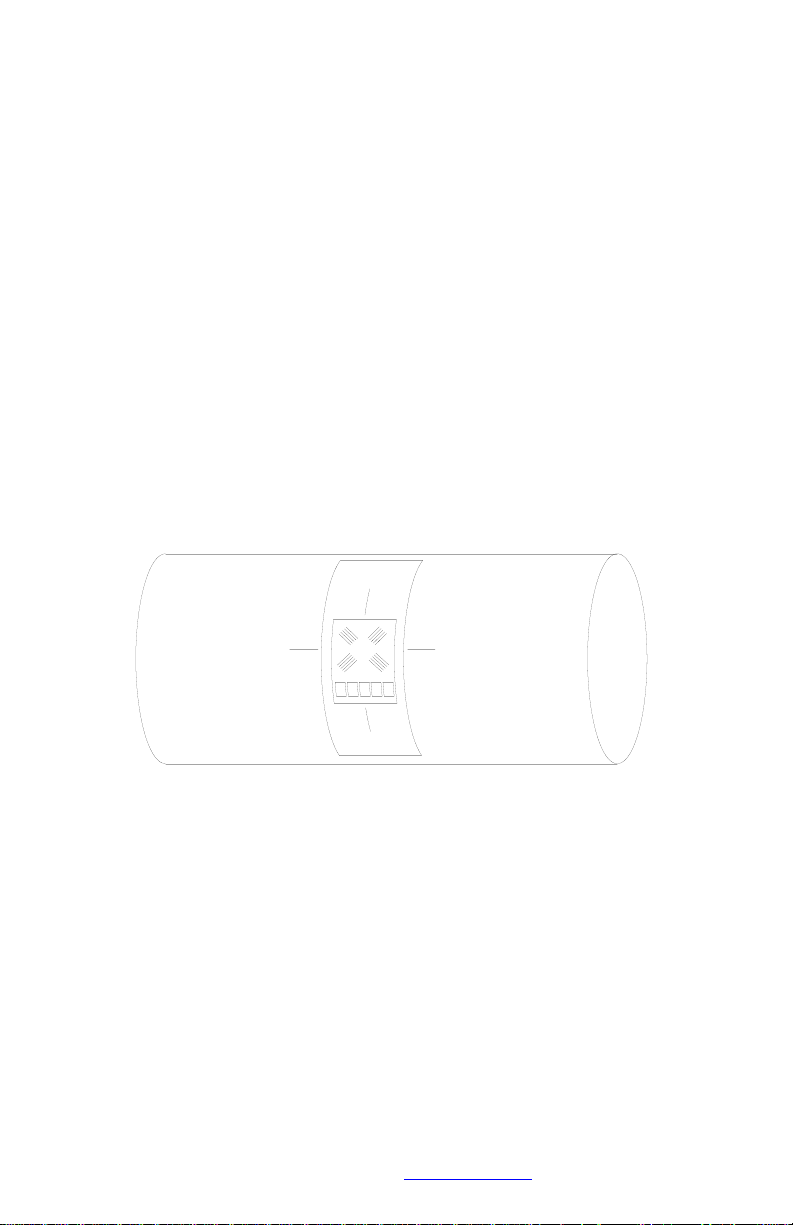
4. The gage needs to be perpendicular to the shaft axis. In general,
this can be accomplished by eye since misalignment of less than
4 degrees will not generate significant errors. For higher
precision, we recommend two methods for marking the shaft:
a. Use a machinist square and permanent marker or scribe for
perpendicular and parallel lines; or
b. Cut a strip of graph paper greater than the circumference of
the shaft. Tape it to the shaft while lining up the edges. Mark
desired gage position with a scribe or permanent marker.
Page 47
This document is subject to change without prior notification.
Binsfeld Engineering Inc. | 231-334-4383 www.binsfeld.com 869610-9_A2 Pg. 45
PREPARING THE GAGE FOR MOUNTING
5. Using tweezers, remove one gage from its package. Using the
plastic gage box as a clean surface, place the gage on it, bonding
side down. Take a 6” piece of PCT-2M Mylar Tape and place it on
the gage and terminal, centered. Slowly lift the tape at a shallow
angle. You should now have the gage attached to the tape.
POSITIONING THE GAGE
6. Using the small triangles located on the four sides of the gage,
place the taped gage on the shaft, perpendicular with the shaft
axis, aligned with your guide marks. If it appears to be
misaligned, lift one end of tape at a shallow angle until the
assembly is free to realign. Keep one end of the tape firmly
anchored. Repositioning can be done as the PCT-2M tape will
retain its mastic when removed and therefore not contaminate the
gaging area.
Figure 1, Strain gage mounting
POSITIONING THE GAGE ON THE SHAFT
7. Gage should now be positioned. Once again, lift the gage end of
the tape at a shallow angle to the surface until the gage is free of
the surface. Continue pulling the tape until you are approximately
1/8” – 1/4” beyond gage. Turn the leading edge of the tape under
and press it down, leaving the bonding surface of the gage
exposed.
8. Apply a very thin, uniform coat of M-Bond 200-Catalyst to the
bonding surface of the gage. This will accelerate the bonding
Page 48

This document is subject to change without prior notification.
Binsfeld Engineering Inc. | 231-334-4383 www.binsfeld.com 869610-9_A2 Pg. 46
when glue is applied. Very little catalyst is needed. Lift the brush
cap out and wipe excess on lip of bottle. Use just enough catalyst
to wet gage surface. Before proceeding, allow catalyst to dry at
least one minute under normal ambient conditions of + 75F and
30-65% relative humidity.
NOTE: The next three steps must be completed in sequence
within 3 – 5 seconds. Read through instructions before
proceeding so there will be no delays.
Have Ready:
M-Bond (Cyanoacrylate) Adhesive
2” – 5” piece of teflon tape
Tissues
MOUNTING THE GAGE
9. Lift the leading edge of the tape and apply a thin bead of
adhesive at the gage end where the tape meets the shaft.
Adhesive should be of thin consistency to allow even spreading.
Extend the line of glue outside the gage installation area.
10. Holding the tape taut, slowly and firmly press with a single wiping
stroke over the tape using a teflon strip (to protect your thumb
from the adhesive) and a tissue (to absorb excess adhesive that
squeezes out from under the tape). This will bring the gage back
down over the alignment marks on the gaging area. This forces
the glue line to move up and across the gage area. A very thin,
uniform layer of adhesive is desired for optimum bond
performance.
11. Immediately, using your thumb, apply firm pressure to the taped
gage by rolling your thumb over the gage area. Hold the pressure
for at least one minute. In low humidity conditions (below 30%) or
if ambient temperature is below + 70 F, pressure application time
may have to be extended to several minutes.
12. Leave the mylar tape on an additional five minutes to allow total
drying then slowly peel the tape back directly over itself, holding it
close to the shaft while peeling. This will prevent damage to the
gages. It is not necessary to remove the tape immediately after
installation. It offers some protection for the gaged surface and
may be left until wiring the gage.
Page 49

This document is subject to change without prior notification.
Binsfeld Engineering Inc. | 231-334-4383 www.binsfeld.com 869610-9_A2 Pg. 47
WIRING THE GAGE
13. Tin each solder pad with a solder dot. (It is helpful to polish the
solder tabs, e.g. with a fiberglass scratch brush or mild abrasive,
before soldering.) Trim and tin the ends of the 4-conductor ribbon
wire. Solder the lead wires to the gage by placing the tinned lead
onto the solder dot and pressing it down with the hot soldering
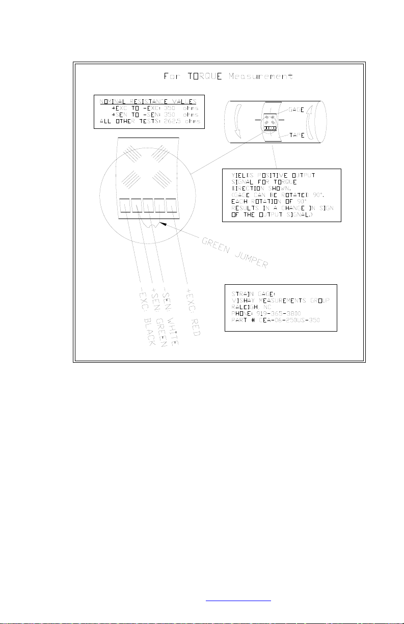
iron. Note: For single-stamp torque gages, a short jumper is
required between solder pads 2 and 4 as shown in the diagram
on the next page
14. Use the rosin solvent to clean excess solder rosin from the gage
after wiring. Brush the gage pads with the solvent and dab with a
clean tissue.
15. Paint the gage area (including the solder pads) with M-Coat A
polyurethane and allow to air dry 15 minutes. This protects the
gage from moisture and dirt. To further protect the gage, apply MCoat J protective coating for protection against moisture, fluids
and mechanical damage.
Page 50
This document is subject to change without prior notification.
Binsfeld Engineering Inc. | 231-334-4383 www.binsfeld.com 869610-9_A2 Pg. 48
16.
Figure 2, Strain gage wiring
Page 51

This document is subject to change without prior notification.
Binsfeld Engineering Inc. | 231-334-4383 www.binsfeld.com 869610-9_A2 Pg. 49
Warranty and Service Information
Limited Warranty
Binsfeld Engineering Inc. warrants that its products will be free from
defective material and workmanship for a period of one year from the
date of delivery to the original purchaser and that its products will
conform to specifications and standards published by Binsfeld
Engineering Inc. Upon evaluation by Binsfeld Engineering Inc., any
product found to be defective will be replaced or repaired at the sole
discretion of Binsfeld Engineering Inc. Our warranty is limited to the
foregoing, and does not apply to fuses, paint, or any equipment, which in
Binsfeld Engineering’s sole opinion has been subject to misuse,
alteration, or abnormal conditions of operation or handling.
This warranty is exclusive and in lieu of all other
warranties, expressed or implied, including but not
limited to any implied warranty of merchantability or
fitness for a particular purpose or use. Binsfeld
Engineering Inc. will not be liable for any special,
indirect, incidental or consequential damages or loss,
whether in contract, tort, or otherwise.
NOTE (USA only): Some states do not allow limitation of
implied warranties, or the exclusion of incidental or
consequential damages so the above limitations or
exclusions may not apply to you. This warranty gives you
specific legal rights and you may have other rights which
vary from state to state.
For service please contact Binsfeld Engineering Inc.:
4571 W. MacFarlane Road
Maple City, MI 49664
Phone: (+1) 231-334-4383
Fax: (+1) 231-334-4903
Internet: www.binsfeld.com
Email: [email protected]
Page 52

FCC Rules Part 15: Computing Devices
This equipment has been tested and found to comply with the limits for a
Class B digital device, pursuant to part 15 of the FCC Rules. These
limits are designed to provide reasonable protection against harmful
interference in a residential installation. This equipment generates, uses,
and can radiate radio frequency energy and, if not installed and used in
accordance with the instructions, may cause harmful interference to
radio communications. However, there is no guarantee that interference
will not occur in a particular installation. If this equipment does cause
harmful interference to radio or television reception, which can be
determined by turning the equipment off and on, the user is encouraged
to try to correct the interference by one or more of the following
measures:
Reorient or relocate the receiving antenna.
Increase the separation between the equipment and receiver.
Connect the equipment into an outlet on a circuit different from
that to which the receiver is connected.
Consult the dealer or an experienced radio/TV technician for
help.
In order to maintain compliance with FCC regulations, shielded cables
must be used with this equipment. Operation with non-approved
equipment or unshielded cables is likely to result in interference to radio
and TV reception.
The user is cautioned that changes and modifications made to the
equipment without the express approval of the manufacturer could void
the user’s authority to operate this equipment.
This device complies with Part 15 of the FCC rules.
Operation is subject to the following two conditions: (1) this device may not
cause interference, and (2) this device must accept any interference that
may cause undesired operation of the device.
This document is subject to change without prior notification.
Binsfeld Engineering Inc. | 231-334-4383 www.binsfeld.com 869610-9_A2 Pg. 50
 Loading...