


®
SPRT
SP-POS88ⅤThermal Receipt Printer
User’s Manual
(Ver 1.00)
Beijing Spirit Technology Development Co., Ltd
Address: No.26,Ave 4,Chuangye Middle Road, Shangdi Information
Industry Park , Beijing, China
Post Code:100085
Tel:+861051661178
Fax:+861051661178-190
E-mail: info@sprt-printer.com

Content
Introduction ...................................................................................................................................... 3
Chapter 1 Feature and Performance ........................................................................................... 3
1.1 Print Performance ............................................................................................................... 3
1.2 Print Paper ........................................................................................................................... 4
1.3 Print Font ............................................................................................................................ 4
1.4 Interface .............................................................................................................................. 5
1.5 Print Control Commands..................................................................................................... 5
1.6 Power Supply ...................................................................................................................... 6
1.7 Operation Environment ....................................................................................................... 6
1.8 Outline Dimension .............................................................................................................. 6
1.9 Model classification ............................................................................................................ 6
Chapter 2 Operation Specification ............................................................................................... 7
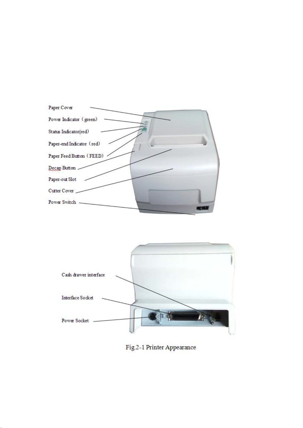
2.1 Printer Appearance .............................................................................................................. 7
2.2 Paper Installation ................................................................................................................. 8
2.2.1 Paper Loading ....................................................................................................... 8
2.2.2 Solution to Paper Jam ......................................................................................... 8
2.3 Interface .............................................................................................................................. 9
2.3.1 Serial Interface ...................................................................................................... 9
2.3.2 Parallel Interface ................................................................................................. 11
2.3.3 BLUETOOH interface connection .................................................................... 14
2.3.4 BLUETOOH binding address ............................................................................ 15
2.3.5 Cash Drawer Interface ....................................................................................... 16
2.3.6 Power Connection .............................................................................................. 17
2.4 Buttons and Indicators ...................................................................................................... 18
2.5 Self-test ............................................................................................................................. 18
2.6 Hexadecimal Printing ........................................................................................................
19

Introduction
POS88Vprinter is a new type line thermal printer, it features in fast
speed print, low print noise, high reliability, perfect print quality and
ribbon needless, avoiding the vexation of regular maintenance.
POS88Vprinter: small in outline dimension, simple operation, and
extensive application, especially suitable for commercial cash
register, PC-POS, bank POS and all kinds of receipts print.
This is a class A product. In a domestic environment this produ
ct may cause radio interference in which case the user may be
required to take adequate measures.
Warning
Chapter 1 Feature and Performance
1.1 Print Performance
● Print method: direct thermal
●
Print paper width: 79.5±0.5mm
●
Print density: 8 dots/mm, 576 dots/line
●
Print speed: approx.250mm/sec.
●
Reliability
(1)Print head life: 100km

Using condition:
*Print 12 × 24 ASCII characters, print 50 lines each time,
intermittent print repeatedly
*Each dot-line printing at the same time should not exceed
25%, each character line and one dot vertical printing
repeatedly should not exceed 11 times
*Use specified thermal paper
(2)Cutter life: 500,000 cuts
Using condition: less than 30 cuts/minute
●
Valid print width: 72mm
1.2 Print Paper
●
Thermal paper roll model: TF50KS-E(Japan paper co.ltd)
AF50KS-E (JUJO THERMAL)
●
Thermal paper roll: Width--- 79.5±0.5mm
Outer Diameter --- 80mm(max.)
Inner Diameter--- 13mm(min.)
Thickness --- 0.06mm~0.08mm
1.3 Print Font
●
ANK Character Set
12×24 dots,1.5(W)×3.00(H)mm
●
GB GB2312-80(Chinese):
24×24 dots,3.00(W)×3.00(H)mm.

1.4 Interface
●
RS-232C Serial Interface:
DB-25 socket (female), supports XON/XOFF and TR/DSR
protocols.
Baudrate: 2400, 4800, 9600, 19200, 38400, 57600, 115200bps
adjustable.
Data structure: 1start bit + (7 or 8) data bits + 1 stop bit.
Parity checking: no parity or odd, even parity optional.
●
Parallel Interface
36-pin,8-bit parallel interface,BUSY/ACK handshaking protocol,
TTL signal level.
●
Ethernet Interface: Normal ethernet interface.
●
USB Interface:USB interface
●
Cash Drawer Control
DC24V,1A,6-pin RJ-11 socket.
1.5 Print Control Commands
● Character print commands: support double-width, double height
print of ANK characters, user-defined characters and Chinese
characters, the character line spacing is adjustable.
●
Graphics print commands: support the print of bit-map graphics
and download bit-map graphics with different density
●
GS bar code print commands: support UPC-A,UPC-E,EAN-13,
EAN-8, CODE39,ITF,CODEBAR,CODE93, CODE128, PDF417,

QR bar code printer.
1.6 Power Supply
● DC24V±10%,2A,A-1009-3P power socket.
1.7 Operation Environment
● Operation temperature: 5~50℃; Relative humidity: 10~80%
● Storage temperature: -40~55℃; Relative humidity: 10~90℃
1.8 Outline Dimension
●200(L)mm×150(W)mm×139(H)mm
1.9 Model classification
Model Interface
SP-POS88VS RS232C Serial Interface
SP-POS88VP Parallel Interface
SP-POS88VM RS232+USB+Ethernet Interface
SP-POS88VU USB Interface
SP-POS88VBT USB+Bluetooth interface
Chapter 2 Operation Specification
2.1 Printer Appearance

2.2 Paper Installation
2.2.1 Paper Loading
POS88V adopts 79.5mm width thermal paper roll.
Steps of Loading Thermal Paper Are as below:
Hold down the upper cover button on the left side, open the
movable upper cover, draw a certain length of the paper roll, put
the paper end on the print head, close the upper cover and press it
downwards lightly.
!Caution!
1. Pay attention to the direction of loading paper,
make the printing surface face to the print head.
2. Please don’t feed or draw the paper forwards or
backwards with hands.
3. Keep clean of the print head, avoid to influence
the printing quality.
2.2.2 Solution to Paper Jam
If cutter jam, turn off the power, and turn on again, the cutter will
be back to original position. If paper jam, open the paper strage

cover, and take out the paper. If the cutter can not be back to the
original position, open the cover of it, and turn the white plastic gear
by the direction suggestive on the cutter by hand to make the cutter
be back to the original position.
2.3 Interface
2.3.1 Serial Interface
The serial interface of SP-POS88Ⅴ printer is compatible with
RS-232C, supports DTR/DSR and XON/XOFF handshaking
protocols, uses DB25 socket (female). The pin order of the serial
port is as Fig.2-2 shows:
Fig.2-2 Pin Order of Serial Port
The pin assignment of serial interface is shown in Fig. 2-3:
Pin
Signal
Signal
Sourc
Description
No.
Name
Directio
e
n
1 FG —— —— Cover ground

2 TXD Output Printer Printer transmits control
code X-ON/X-OFF and data
to host
3 RXD Input Host Printer receives data from
host
4 RTS Output Printer The same with 20pins DTR
signal
6 DSR Input Host Signal “MARK” means the
host is busy and can not
receive data. Signal
“SPACE” means the host is
ready to receive data.
7 GND —— —— Signal Ground
20 DTR Output Printer Signal “MARK” means the
host is busy and can not
receive data. Signal
“SPACE” means the host is
ready to receive data.
Fig. 2-3 The pin assignment of serial interface
Note: (1)“Source” denotes the source that signal come from;

(2)Logical signal level is EIA.
The baud rate and data structure in serial interface mode is
9600bps, 8-bit data bits, no parity bit and 1 stop bit.
The serial interface of SP-POS88Ⅴ can be connected to standard
RS-232C interface. When it is connected to IBM PC or its
compatible machine, connection can accord to Fig.2-4.
3
RXD
DTR
RTS
TXD
DSR
Printer
25PIN Socket
Fig.2-4 Connection between SP-POS88V and IBM PC Serial Interface Sketch Map
20
4
2
6
7
3
TXD
6
DSR
8
CTS
2
RXD
4
5
DTR
IBM PC
DB9 Socket
RXD
DTR
RTS
TXD
DSR
Printer
25PIN Socket
3
20
4
2
6
7
2
TXD
6
DSR
5
CTS
3
RXD
20
7
DTR
DB25 Socket
IBM PC
2.3.2 Parallel Interface
The parallel interface of POS88 Ⅴ printer is compatible with
CENTRONICS, supports BUSY or ACK handshaking protocol,
uses
36pin CENIRONICS socket (female)
The pin assignment of DB25 parallel interface is as Fig. 2-5 shows:

Pin No. Signal Direction Description
1 STROBE In Strobe pulse to latch data, Reading
occurs at falling edge.
2 D1 In These signals represent the 1st bit to
8th bit of the parallel data
representatively, each signal is at
HIGH level when data is logic 1, and
LOW when data is logic 0.
3 D2 In
4 D3 In
5 D4 In
6 D5 In
7 D6 In
8 D7 In
9 D8 In
10 ACK Out Answer pulse, LOW level signal
indicates that data have already been

received and the printer gets ready to
receive the next data.
11 BUSY Out HIGH level signal indicates that the
printer is BUSY and can not receive
data.
12 PE Out HIGH level signal indicates that paper
is end.
13 SEL Out Pulling up to HIGH level signal by a
resistor
17 FG --- Signal Cover
18 Logic-H --- Logic “1” level
32 nFault Out Low level means the printer is at fault
14,15,17
18,34,36 NC
16,19~3
GND --- Grounding logical 0 level
---
No connection
0, 33
35 +5V --- +5V power
Fig.2-5 36Pin assignment of parallel interface

Note: (1)“In” denotes input to the printer,“Out” denotes output from
the printer.
(2)Signal level is TTL standard.
The timing chart for interface signal of parallel interface is as
Fig.2-6shows:
Fig.2-6 Signal Timing Chart of Parallel Interface
2.3.3 BLUETOOH interface connection
The handheld terminal, notebook computer or other terminals with
Bluetooth interface can print by POS80 driver. The printer Bluetooth
is compatible with Bluetooth 2.0 standard. Power Level is CLASS 2,
the valid distance is 10m. The printer Bluetooth is slave device. The
initial device name is POS80 BT Printer and initial password is
“1234”. The user can change device name and password, etc by
<T9 Setting Tool>. The detailed method about changing device
name and password can be checked in Help file of <T9 Setting
Tool>.

Before printing, the printer needs to pair with the Bluetooth host
device. The pair needs to be sponsored by the host device. Usually,
the pair steps are as below,
Turn on the printer
1. The host device searches the external Bluetooth device
2. If there are several external Bluetooth devices, choose printer
“POS80 BT Printer”
3. Input password “1234”
4. Finish pairing.
About the detailed methods of pairing, pls check The Bluetooth
Function Manual of the host device.
Note:
1. When pairing, the printer power must be in on status.
2. After the printer Bluetooth is paired with host device Bluetooth
successfully, it won’t be searched and paired with other host
Bluetooth device, until the Bluetooth pairing with current host
device stop.
3. After pairing successfully, the “Power” indicator will flicker.
2.3.4 BLUETOOH binding address
If the printer has binding address: The printer will remember the
paired host device address automatically. Once the printer

remembers the address, the connection will be only between it and
the remembered host device and can’t be searched or paired by
other device. So if the printer wants to connect with other device, it
needs to clear away the remembered address or set the mode to
no binding address. Reset the binding address mode (Set or
Cancel) will clear away the remembered address automatically.
If no binding address: The printer can be searched or paired by
other host device.
Therefore, if hope the printer to be connected with the only
specified host device and not with other host device, it is better to
binding the address. The detailed methods of setting binding
address can be checked in “T9 Setting Tool”.
2.3.5 Cash Drawer Interface
The cash drawer interface of POS-POS88Ⅴ adopts RJ-11 6-pin
socket, as Fig.2-7 shows:
Fig.2-7 Cash Drawer Interface
The pin assignment is as below:

Pin No. Signal Direction
1 Chassis Ground ——
2 Cash drawer driver signal 1 Out
3 Cash drawer on/off status signal In
4 +24VDC ——
5 Cash drawer driver signal 2 Out
6 Signal ground ——
2.3.6 Power Connection
POS88 Ⅴ uses the external power supply adopter as
24V±10%、2A,
power socket is A-1009-3P model, as Fig. 2-10 shows:
Fig.2-8 Power Socket
The pin assignment is as below:
Pin No. Signal
1 +24VDC
2 Ground
3 NC

2.4 Buttons and Indicators
There is one button and three indicators on POS88Ⅴ printer.
【FEED】is paper feeding button, the function of its enabling or
disabling the button on/off can be set by print command, when the
button is enabled, press 【 FEED 】 button, then the paper
presenting driver starts up and paper fed into the printer; release
【FEED】 button, paper feeding stops. The green POWER light is
the power indicator, red ERROR light is status indicator, it is dark
when the printer works normally, while it flashes when reporting an
abnormal emergency, as the following form shows:
Error Indicator and Buzzer
Description
Status
Paper ending “ERROR” indicator
Print head
uplift
Print head
overheat
Auto cutter
Position Error
flashes
Buzzer rings Put down print head
Hurried buzzer ring Recovers automatically
Buzzer rings and
indicator blinks
Paper is running out
when the print head
cools.
Impossible to recover,
check if there is paper
jam.
When any error shown above occurs, pin “nFault” of parallel
change to “0” level, and send 1 bit wrong code through serial TXD
by itself, it can also send out the printer state by answer the ESC v
command.
Red indicator of “Paper Out ” is the paper out indicator. When
there is no paper in printer head, it will light, and it is off under
normal status.
2.5 Self-test
The self-test will check the condition of printer, if the printer
prints out the self-test receipt correctly, it means the printer works
normally, except interface with host. Otherwise it needs to repair.
The self-test will print out 96 ANK characters, default code page,
name of Chinese Character library, interface setting and software
version.
Way of self-test: hold down【FEED】button and turn on the

power, self-test begins automatically at this moment.
2.6 Hexadecimal Printing
Turn on the printer according to the step below, it will enter the
mode of Hexadecimal Printing
1.Open the cover;
2.Hold down【FEED】button,and connect with power;
3.Close the cover, the printer will print out 3 lines as below:
Hexadecimal Dump
To terminate hexadecimal dump,
Press FEED button three times.
This means the printer has entered hexadecimal printing mode,
and under this mode, all of the input will be printed out as
hexadecimal number, feed one line with single-click of “FEED”
button, after 3 times, it will print out “*** Completed ***”,and exit
hexadecimal printing mode.

FCC Statement
This equipment has been tested and found to comply with the limits for a Class B digital device,
pursuant to Part 15 of the FCC Rules. These limits are designed to provide reasonable
protection against harmful interference in a residential installation. This equipment generates
uses and can radiate radio frequency energy and, if not installed and used in accordance with
the instructions, may cause harmful interference to radio communications. However, there is
no guarantee that interference will not occur in a particular installation. If this equipment does
cause harmful interference to radio or television reception, which can be determined by turning
the equipment off and on, the user is encouraged to try to correct the interference by one or
more of the following measures:
-- Reorient or relocate the receiving antenna.
-- Increase the separation between the equipment and receiver.
-- Connect the equipment into an outlet on a circuit different from that to which the receiver is
connected.
-- Consult the dealer or an experienced radio/TV technician for help.
This device complies with part 15 of the FCC Rules. Operation is subject to the following two
conditions:(1) This device may not cause harmful interference, and (2) this device must accept
any interference received, including interference that may cause undesired operation.
Changes or modifications not expressly approved by the party responsible for compliance
could void the user's authority to operate the equipment.
 Loading...