

Beijing Noitom Technology MSW P R 01 Users manual
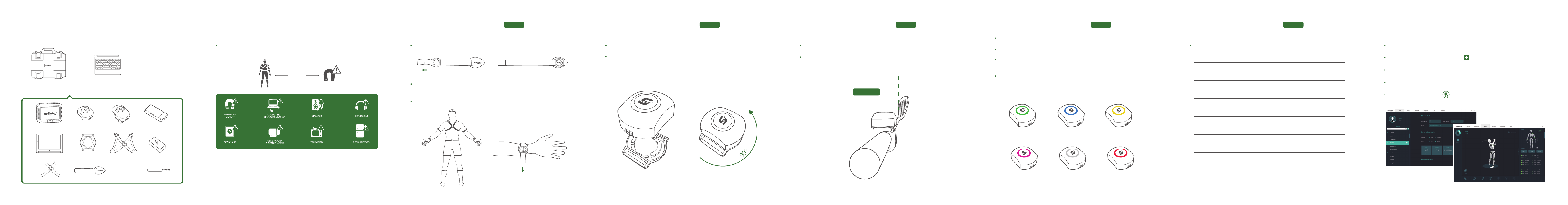
STEP 1 MYSWING PROFESSIONAL INCLUDES: STEP 2 IMPORTANT
Keep Away From Magnetic Fields. Connect the straps to the sensor bases.
Case Keyboard
3 Feet
STEP 3 GETTING STARTED
Use the appropriate length of strap that ts the player for each segment. Attach
the straps according to the diagram.
Attach the appropriate label (e.g. forearm, thigh, etc.) to the straps, if desired.
PART 1 PART 2 PART 3 PART 1 PART 2
STEP 3 GETTING STARTED
Place the sensors into the bases.
Rotate the sensors 90 degrees counter-clockwise. Handle the sensors gently,
do not over tighten.
STEP 3 GETTING STARTED
Attach shaft sensor just below the grip with charging contacts pointing down.
Align the shaft sensor parallel to the club face as shown.
Parallel
STEP 4 THE SENSOR LED’S
To turn on, hold the button for 2 seconds.
To turn off, hold the button for 5 seconds.
To reset sensor, turn on, then hold the button for 10 seconds.
( Sensor must be fully recharged after reset. )
LED Colors
Green ( frequency 1 ) is the default.
( multiple systems in close proximity must use different frequencies )
LED Status
Slow Blink
Fast Blink Working
Double Blink every 3
seconds
Standby
Sleep Mode
STEP 5 CONNECT TO TABLETSTEP 4 THE SENSOR LED’S
Start mySwing Professional software.
Add new student by clicking the plus button.
Enter Student’s Information, Height, Wingspan, and Agree to the Terms of Use.
Proceed to Screen/Swing Tab.
Click on the Connect icon and follow the on-screen instructions.
Charging Case Body Sensor ×17 Shaft Sensor ×2 Receiver
Tablet Shoulder Harness Transformer for Charging Case
Shoulder Harness
Body Sensor Base ×15
Velcro Straps ×15 Antenna
MySwing Pro sensors must always be kept at least 3 feet away from all magnetic
elds. Magnetizing a sensor will cause noticeable errors in the avatar. If this occurs
repeatedly, contact Customer Service to have the sensor recalibrated or replaced.
frequency 1 frequency 2 frequency 3
frequency 4 frequency 5
charging, low battery,
or sensor error
Blinking Red LED
Constant Red Light
outside of charging dock
Indicates Low Battery
( approximately 20 minutes remaining )
Sensor Error
( Reset Sensor )
powered by
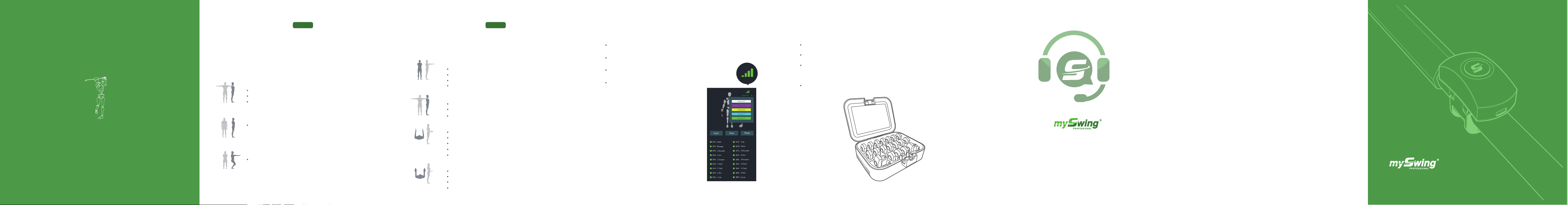
STEP 6 CALIBRATION
PART 1
STEP 6 CALIBRATION
PART 2
STEP 7 AUTOMATIC FREQUENCY CHANGE
* only necessary if using multiple systems
STEP 8 CHARGING THE SENSORS
www.myswing.com
Follow the on screen calibration procedure. Make sure antenna is facing player
before proceeding.
Quick Calibration
T Pose
Feet are straight and square to the target line, six inches apart.
Hold arms horizontal in both directions.
Upper arms aligned with the body.
A Pose
Feet remain in the same position with thumbs placed on the seams
of the pants.
S Pose
Feet remain in the same position with arms extended, with slight
knee bend.
Advanced Calibration
7 Pose
Feet are straight and square to target line, six inches apart.
Arms extended in front of player.
Upper arms parallel to each other.
Upper arms parallel to the ground.
T Pose
Feet remain in same position.
Hold arms horizontal in both directions.
Upper arms aligned with the body.
L Pose
Feet remain in same position.
Stand tall and straight.
Upper arms as close to the body as possible.
Forearms parallel to the ground.
Palms facing each other and thumbs pointing up.
LL Pose
Feet remain in same position.
Remain in L Pose posture.
Rotate both forearms out 90 degrees
Use the middle ngers as the axes of rotation.
(or as much as possible)
Click the channel button in the top right corner.
Select the channel.
Check sensors for correct LED color.
If a sensor’s LED color is not correct,
it must be changed manually.
Gently place each sensor into the charging case.
Close the charging case cover.
Connect the transformer to the charging case, make sure all LED’s are
constant red.
When a sensor is fully charged, the red LED will turn off.
Contact Support
TOLL FREE Support Number 1-844-843-1270
or
E-mail:
support@myswing.com
Any Changes or modications not expressly approved by the party responsible for compliance could void the
user's authority to operate the equipment.
This device complies with part 15 of the FCC Rules. Operation is subject to the following two conditions: (1) This
device may not cause harmful interference, and (2) this device must accept any interference received, including
interference that may cause undesired operation.
Note: This equipment has been tested and found to comply with the limits for a Class B digital device, pursuant
to part 15 of the FCC Rules. These limits are designed to provide reasonable protection against harmful
interference in a residential installation. This equipment generates, uses and can radiate radio frequency energy
and, if not installed and used in accordance with the instructions, may cause harmful interference to radio
communications. However, there is no guarantee that interference will not occur in a particular installation. If this
equipment does cause harmful interference to radio or television reception, which can be determined by turning
the equipment off and on, the user is encouraged to try to correct the interference by one or more of the
following measures:
—Reorient or relocate the receiving antenna.
—Increase the separation between the equipment and receiver.
—Connect the equipment into an outlet on a circuit different from that to which the receiver is connected.
—Consult the dealer or an experienced radio/TV technician for help.
MySwing Golf, Inc.
16411 N. 90th St. Ste. 101
.
Scottsdale, AZ 85260
QUICK START GUIDE
 Loading...