

Beijing Noitom Technology HI5 LG 01, HI5 RG 01 User Manual

Noitom Hi5 VR Glove
User Guidelines
Ver. 1.3

Version Number
Version Date
Version Reason
1.0
2017.4
Initial version
1.1
2017.09.12
1. RF performance revised;
2. Mounting optical tracking
device revised;
3. Wearing glove revised;
4. Calibration motions and steps
revised.
1.2
2017.11.22
1. RF performance for multiple
user revised;
2. Vibration meaning changed;
3. Battery life extended.
1.3
2018.2.1
1. Add FCC statement
Version Control

Contents
1. Introduction .................................................................................................. 1
2. Hardware Parts ............................................................................................ 2
2.1 Components ........................................................................................................... 2
2.2 Interaction Interfaces .............................................................................................. 3
2.3 Features.................................................................................................................. 4
2.4 Radio Frequency (RF) ............................................................................................ 4
2.5 Usages.................................................................................................................... 5
2.5.1 Basic Operation Steps ................................................................................... 5
2.5.2 Pairing Gloves ................................................................................................ 6
2.5.3 Demagnetization ............................................................................................ 7
3. Mechanical Parts ......................................................................................... 9
3.1 Mounting Optical Tracking Devices ........................................................................ 9
3.2 Wearing Gloves .................................................................................................... 12
4. SDK ........................................................................................................... 14
5. Calibration Instructions .............................................................................. 15
5.1 Notice .................................................................................................................... 15
5.2 Calibration Steps .................................................................................................. 15
Hi5 VR Glove
Developer Guidelines
NOITOM corporation
Dec.2017 V1.2
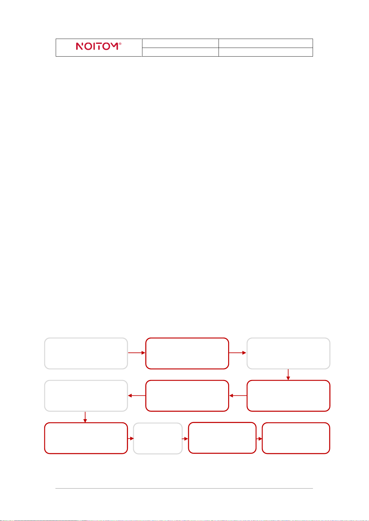
sample (Unity/Unreal)
Turn on Hi5 gloves, and
they’ll connect to dongle
automatically
Put on HMD
Demagnetization
Calibration
sample instruction)
1. Introduction
This document describes the development guidelines for content developers. It contains
information on how to use the Noitom Hi5 VR Glove to enable motion capture tracking of
the user’s hands and fingers.
Notice:
1. Noitom Hi5 is provided as a pair. You may use them with both hands or with just one
hand and one Glove.
2. It’s needed to use Noitom Hi5 together with optical tracking devices in order to gain
the absolute position of your hands and forearms in a tracked area and do calibration
correctly.
3. Noitom Hi5 Glove can be used on win7/8/10.
4. Currently both VIVE tracker and controller are supported as optical tracking devices
for Hi5 and mounted on Hi5 gloves.
5. You are suggested NOT to hold VIVE controller or any other magnetic or ferrous
objects in hand when wearing Hi5 glove, since it will influence the motion capture
performance.
Basic using steps (for reference):
Set VIVE ready
Open Hi5 calibration
Mount VIVE trackers
onto Hi5 gloves
Turn on trackers, and
pair them to steam
Plug Hi5 dongle into
HMD/PC
Put on Hi5 gloves
Hi5 VR Glove Developer Guidelines 1
(follow Hi5 calibration
Hi5 VR Glove
Developer Guidelines
NOITOM corporation
Dec.2017 V1.2
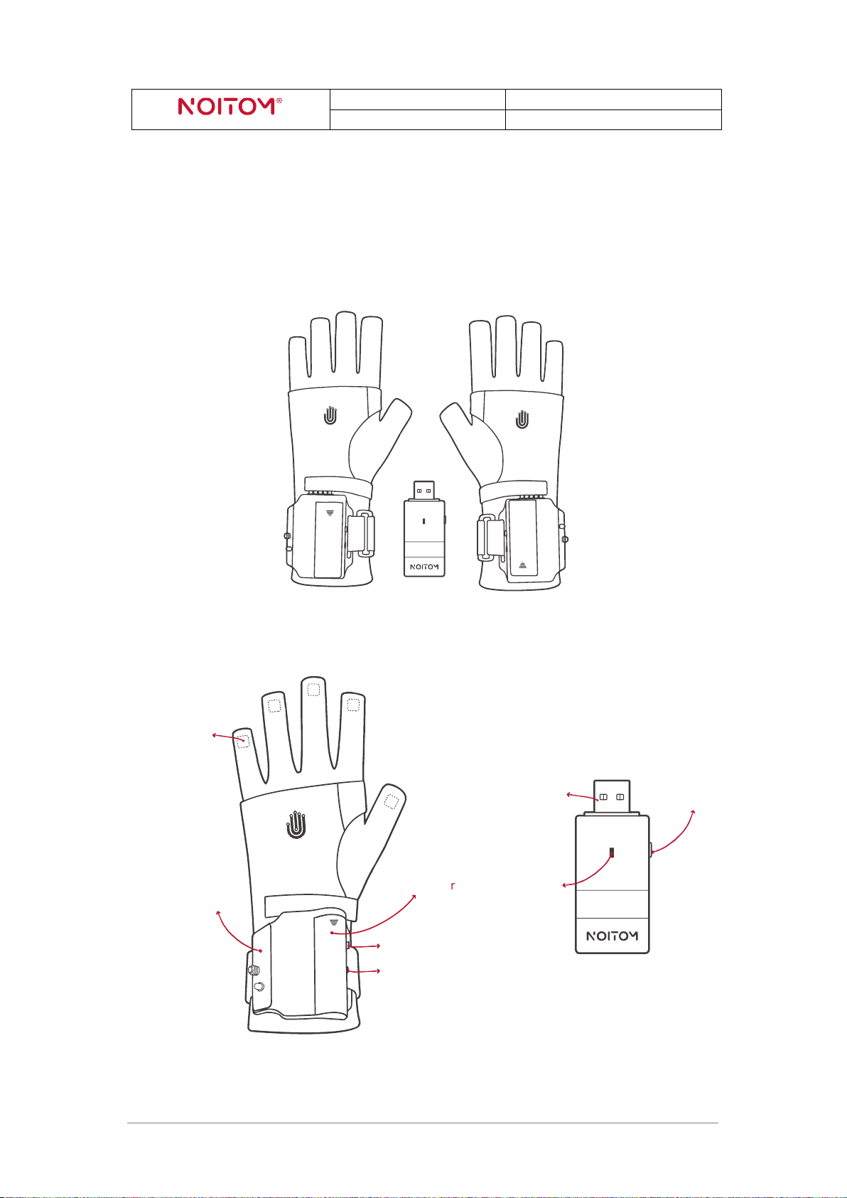
( Figure 2.1-1 )
( Figure 2.1-2 )
Sensors
(bolt and stabilizing pin)
AA battery cover
Button
Indicator light
USB connector
Indicator light
Button
2. Hardware Parts
2.1 Components
Noitom Hi5 comes packaged with 1 pair of Hi5 Gloves (“Glove”) and 1 USB 2.0
transceiver (“Dongle”):
Mounting surface
Hi5 VR Glove Developer Guidelines 2
Hi5 VR Glove
Developer Guidelines
NOITOM corporation
Dec.2017 V1.2
Function
Operation and Indication
On Glove/Dongle
Turning on the Glove
Press the button when the Glove is
powered off (click)
Glove
Turning off the Glove
Press and hold the button for 5
seconds (release after the indicator
light turns off)
Glove
Entering pairing mode
Press and hold the buttons for 3
seconds (release when the indicator
lights turn on to a solid state)
Glove & Dongle
Manually switching working
frequency
Short press the button (click)
Dongle
Triggering button event
Short press the button (click)
Glove
Meaning
Indicator Light State
On Glove/Dongle
Powered off
Turned off
Glove
Standby
Breathing
Glove & Dongle
Pairing mode
1Hz flashing (slowly flashing)
Glove & Dongle
Working mode
20Hz flashing (rapid flashing)
Glove & Dongle
The current ambient
environment has magnetic
interference
Solid state turned on (in working
mode)
Glove
Error 01
(Self-test error)
Solid state turned on (right after
power on)
Glove & Dongle
Error 02
(enter Boot mode)
3s off, 0.1s on
Glove & Dongle
2.2 Interaction Interfaces
There is one button and one indicator light for each Glove and each Dongle. The
interaction lookup table is as follows:
Button Functions:
Indicator Light States:
( Table 2.2-1 )
Notice:The indicator light on the Gloves will turn RED when the battery power is low.
Hi5 VR Glove Developer Guidelines 3
( Table 2.2-2 )
Hi5 VR Glove
Developer Guidelines
NOITOM corporation
Dec.2017 V1.2
Meaning
States
On Glove/Dongle
Glove power on
Vibrate for 0.5s
Glove
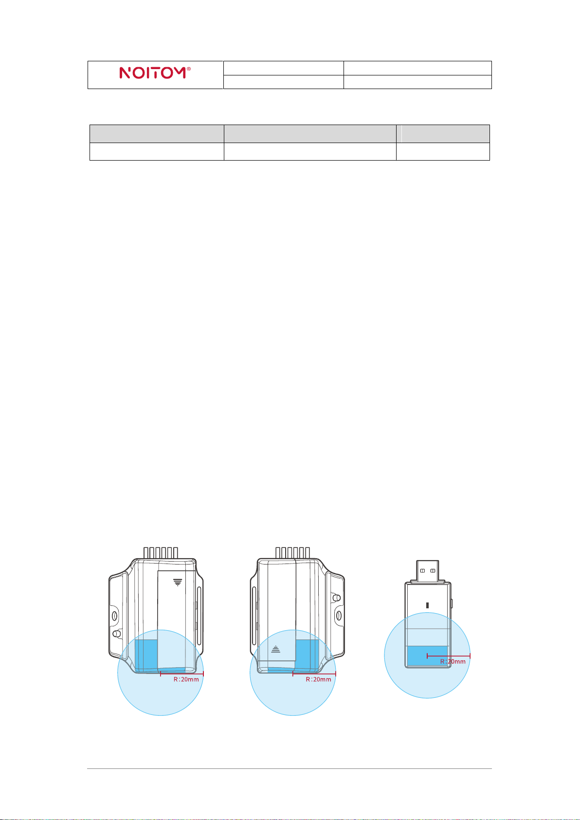
( Figure 2.4-1: Restricted Area of Antenna )
Vibration States:
( Table 2.2-2 )
2.3 Features
9-DOF IMU for 5 fingers and the back of hand
Vibration feedback for each Glove
Supply voltage range of 1.0-1.5VDC with one AA battery for each Glove
Supply voltage range of 5±0.25VDC for Dongle
7 hours of working time with 2100mAh Alkaline battery
Latency less than 5 ms (From motion to SDK, under clean RF condition)
Output date rate up to 180Hz
RF working area: 5m×5m (open area without interference)
automatic channel-switching to avoid RF interference
2.4 Radio Frequency (RF)
1. Working frequency range: 2400MHz~2483.5MHz
2. Restricted Area of Antenna
The figure below illustrates the “keep out” area where only nonmetallic parts of the accessory
should be inside (spherical radius=20mm and the center is antenna feed point).
Hi5 VR Glove Developer Guidelines 4
 Loading...