

Beijing Landwell Electron Technology LW19990824 User Manual
Beijng Landwell Electron Technology Co, Ltd
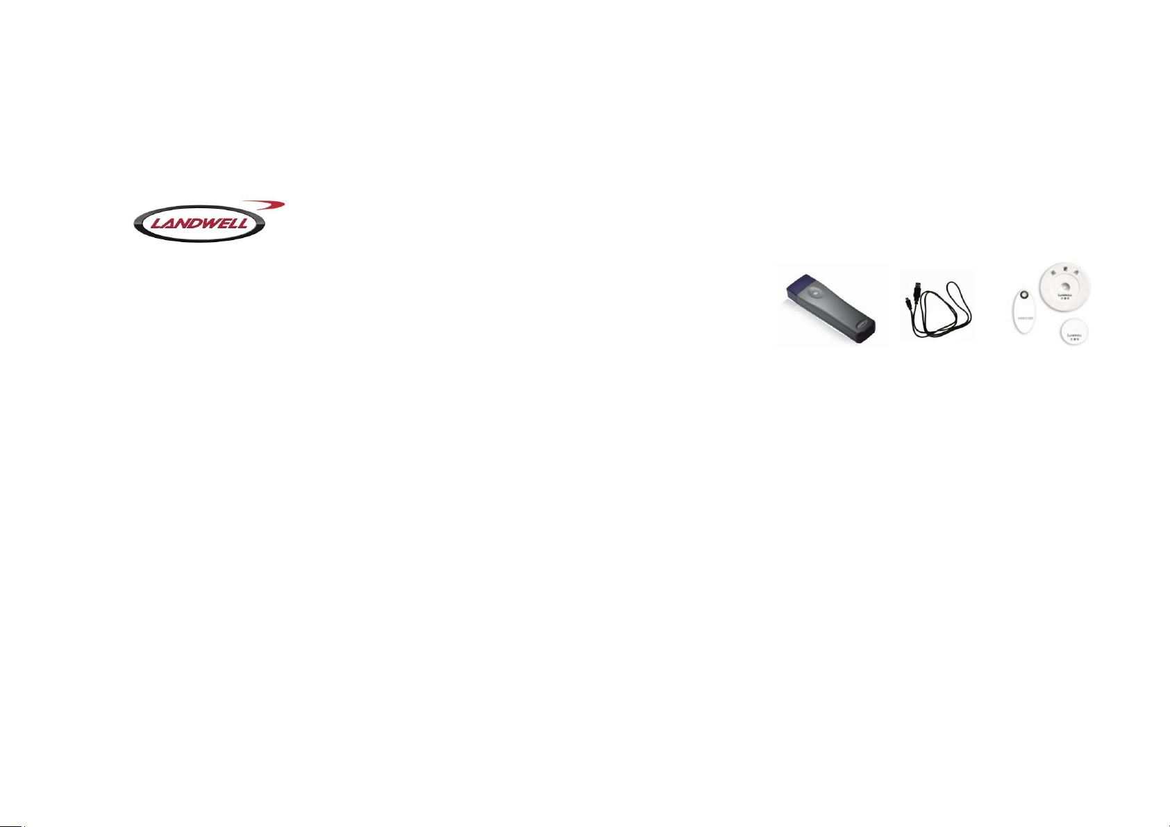
L-3000EF Proximity Guard Tour System Manual
This product has passed ROHS certification
Important Announcement
1, Thanks for purchasing Landwell L-3000EF proximity
guard tour system. Please read the manual carefully
before use. When you begin to use L-3000EF guard
tour reader, Landwell believes that you have read this
manual carefully.
2, As the related contents of the manual may change
without prior notice, the products shall prevail. For more
information please check the company website
(www.guard361.com/)or call us +86-01-84717640.
3, As this is a mobile patrol product, we strongly
recommend that you create data backup when using.
Data loss caused from hardware damage is excluded
from the warranty, which is only effective for hardware
itself.
FCC statement:
This device complies with part 15 of the FCC Rules.
Operation is subject to the following two conditions:
(1) This device may not cause harmful interference, and
(2) this device must accept any interference received,
including interference that may cause undesired
operation.
Changes or modifications not expressly approved by the
party responsible for compliance could void the user's
authority to operate the equipment.
This equipment has been tested and found to comply
with the limits for a Class B digital device, pursuant to
part 15 of the FCC Rules. These limits are designed to
provide reasonable protection against harmful
interference in a residential installation. This equipment
generates uses and can radiate radio frequency energy
and, if not in-stalled and used in accordance with the
instructions, may cause harmful interference to radio
communications.
However, there is no guarantee that interference will not
occur in a particular installation. If this equipment does
cause harmful interference to radio or television
reception, which can be determined by turning the
equipment off and on, the user is encouraged to try to
correct the interference by one or more of the following
measures:
—Reorient or relocate the receiving antenna.
—Increase the separation between the equipment and
receiver.
—Connect the equipment into an outlet on a circuit
different from that to which the receiver is connected.
—Consult the dealer or an experienced radio/ TV
technician for help.
The First Chapter
This system is made up of patrol reader/communication
line /Checkpoint/software. The accessories include the
computer and printer. Specific steps are as follows.
1. System Directions:
1.1) Patrol reader, also called collector, is carried by
patrol man during patrol rounds. Each checkpoint,
collection time and patrol man name etc will be collected
as one piece of data, which is saved after analysis.
Then data will be uploaded to computer through
communication line.
1.2) Transmitting line: also called communication line, it
arranges the data within the collector and transmits
them to the computer.
1.3 ) Information tag(checkpoint)────The information
tag is divided into checkpoint tag and personnel tag.
One information tag can only be setup as checkpoint tag
or personnel tag. It cannot be setup as a personnel tag
after it is already a checkpoint tag.
1.3)a checkpoint tag: according to patrol plan, a

checkpoint tag stands for a patrol point, which is placed
at the patrol site or equipment. Through software the
information tag can be setup as different checkpoint
name which it relates to.
1.3)b personnel tag: this is the patrol man‘s ID tag.
Some tasks are carried out according to group of patrol
man. Every group shares one reader. Every patrol man
carries his own personnel tag so a reasonable patrol
performance check is attainable.
1.4) Software management system ──── it analyzes
the related data uploaded and after data processing, it
offers detailed patrol report. The software will match the
patrol report with plan, and correctly process the patrol
result data.
2. Hardware Directions
2.1) Patrol reader: when patrol man reaches the
planned site, he presents the reader head to the
checkpoint tag within 5cm distance (the tag frequency
decides the distance).When the reader sends out
"beep" sound and the LED lights 3 times(the same tag
cannot be reread continuously with the same reader.
One minute is the minimum interval before reread. The
LED will light once when reread without proper time
interval ),it means the data is collected to the reader
successfully.
2.2) Communication line: connect communication line
USB head to the computer USB port, the other side to
the reader corresponding port.
2.3) Information tag: first stir super glue(like AB glue)
evenly at the rate of 1:1,spread it on the back of the
patrol tag. Paste the patrol tag to the patrol point(like the
surface of cement ,hard brick wall or other strong object.
Choose flat surface before pasting the tag. If the surface
is coarse, use sand paper to polish it.)
3. Software Setup and Usage
Please read the software manual carefully before
software installation. Familiarize with the software step
by step. The software administer’s access is Admin, the
default pin is 333.
3.1) Information tag setup: operate according to
software requirement and the client demands :patrol
record upload ——first clear the old data in the reader
through communication line.(by transmitting the data to
computer after connecting reader with computer ,the
reader's stored data is cleared. The data can be
retransmitted to software if the reader does not read
new tag. If new tag is read, the new data will cover all
the old data and it becomes the first new data
record).Then use this reader to read all the checkpoint
tags in order. Now upload these data to the related
checkpoint setup or personnel setup.
Specific operation method is as follows
a Plan setup: According to the client's situation, setup
the patrol route points, where the patrol tags will be
fixed.
b Tag reading: after checkpoint tag is installed, use the
reader without data to read all the tags once, then
upload the data to the checkpoint setup from software.
Edit the checkpoint name following the reading order.
Another way is before checkpoint tag installation, use
reader to collect all the tags’ ID number. It is better to
write down the ID number by its last 5 to 6 digits
together with the point name it stands for. This is to
link the tag ID number in the software with the
checkpoint tag.
System Installation and Usage Considerations
1) Let the reader's LED face you. Hold the reader like
a pen with hand and arm at a 90 degree angle.
2) Place the patrol reader with the checkpoint tag
surface at a 45 degree angle. When the reader's LED
lights 3 times and the beeper sounds, data collection is
done. (If it is noisy on site, you can reread the tag to
make sure data is collected. If the LED lights once, it
shows the first time reading is successful.)
3) Please transmit correct tag ID number for
checkpoint and personnel setup, and input correct name
for each checkpoint and personnel. Each tag number
and related checkpoint or personnel is unique. One
information tag can only be setup as a checkpoint or
personnel tag, it cannot be both at the same time.
4) If the data collected are less than 10,000 pieces
after patrol, all the data can be uploaded through the
communication line. The data will automatically be
cleared during transmittance. The reader can transmit
the data again if it does not read new data. This function
avoids data loss if problem occurs.
5) Do not read data more than the reader's capacity
 Loading...