

Page 1

Vital Sign Monitor
Mode: MD2000C
Version:1.0
Page 2

Copyright
Our company owns all rights to this unpublished work and intends
to maintain this work as condential. Our company may also seek to
maintain this work as an unpublished copyright. This publication is to
be used solely for the purpose of reference, operation, maintenance or
repair of our equipment. No part of this can be disseminated for other
purposes.
In the event of inadvertent or deliberate publication, our company intends
to enforce its right to this work under copyright laws as a published
work. Those having access to this manual may not copy, disseminate
or disclose the information in this work unless expressly authorized by
our company.
All information contained in this manual is believed to be correct.
Our company shall not be liable for errors contained herein nor for
incidental or consequential damages in connection with the furnishing,
performance, or use of this material. This publication may refer to
information and protected by copyrights or patents and does not convey
any license under the patent rights of our company, nor the rights of
others. Our company does not assume any liability arising out of any
infringements of patents or other rights of third parties.
Our Company reserves the right to make changes in specications and
features shown herein, or discontinue the product described at any time
without notice or obligation. Also, content of the manual is subject to
change without prior notice.
.
All Rights Reserved
Issue Date: July 18, 2018
Version: Ver1.0
CONTENT
CHAPTER 1 INTRODUCTION .........................................................................1
1.1 About the Manual....................................................................................... 1
1.2 Contraindications ....................................................................................... 1
1.3 Safety Information ..................................................................................... 1
1.4 Intended Use ............................................................................................. 4
1.5 Electromagnetic Interference..................................................................... 4
1.6 Symbols Denition ..................................................................................... 4
1.7 Product Properties ..................................................................................... 5
CHAPTER 2 GENERAL DESCRIPTIONS .......................................................6
2.1 understanding the monitor ......................................................................... 6
2.2 Power supply ............................................................................................. 8
2.3 Charging the device................................................................................... 8
2.4 Check the proper function of the device and accessories ......................... 8
2.5 Power off .................................................................................................. 9
CHAPTER 3 Setting ........................................................................................10
CHAPTER 4 Take a measurement ................................................................17
4.1 Preparation ................................................................................................ 17
4.2 NIBP .......................................................................................................... 18
4.3 SpO2, PR and PI ....................................................................................... 23
CHAPTER 5 MAINTENANCE .......................................................................... 28
5.1 Examination ............................................................................................... 28
5.2 Cleaning and Disinfection ......................................................................... 28
5.3 Troubleshooting ........................................................................................ 28
5.4 Warranty and Repair ................................................................................. 29
CHAPTER 6 SPECIFICATIONS .....................................................................32
CHAPTER 7 Compliance Information for EMC Test ....................................37
Page 3

1
CHAPTER 1 INTRODUCTION
1.1 About the Manual
Before using the MD2000C vital sign monitor, the user must carefully
read this manual so that the user can operate the monitor properly and
make it reach the specic safety standard and performance index.
This manual explains how to set up and use the monitor. Important safety
information relating to general use of the monitor appears after this
introduction. Other important safety information is located throughout
the text where appropriate.
Note: There requires no routine calibration, safety maintenance or inservice during the monitor’s life.
1.2 Contraindications
• Active patients.
• Intravascular dyes such as indocyanine green or methylene blue.
• Signicant levels of dysfunctional hemoglobins (such as carbonxyhemoglobin or methemoglobin).
• The presence of high ambient light. Shield the sensor area (with a
surgical towel, or direct sunlight, for example) if necessary.
• Venous pulsations may cause erroneous low readings(e.g.
tricuspid value regurgitation)
• Venous congestion may cause under reading of actual arterial
oxygen saturation. Therefore, assure proper venous outow from
monitored site. Sensor should be not below heart level ( e.g. sensor
on hand of a patient in a bed with arm dangling to the oor)
• Avoid placing the sensor on any extremity with an arterial catheter,
intravascular line or blood pressure cuff.
• Exercise caution with poorly perfuse patients; skin erosion and/or
pressure necrosis may occur.
• Do not use the monitor when the patient in cardiac arrest or in
debrillation.
1.3 Safety Information
Warnings: alert the user to potential serious outcomes, such as injury or
adverse events to the patient or user.
Cautions: alert the user to exercise care necessary for the safe and
Page 4

2 3
medical electrical equipment.
• Chemicals from a broken panel are toxic when ingested. Use
caution when the monitor has a broken display screen.
• Debrillation protection only implement on the ECG cable which
has the debrillation function.
• When using debrillation, it needs to remove other non-debrillation
applied parts from patients.
• The use of the device is restricted to one patient at a time.
• Use a debrillator on a patient, the device requires special
protection when the discharge of a debrillator affects the device.
• Please use the accessories that approved by the manufacturer.
• If the device has the battery, it still working after interruption of the
supply mains exceeding 30s. Or else it power off.
• PACEMAKER PATIENTS. Rate meters may continue to count
the pacemaker rate during occurrences of cardiac arrest or some
arrhythmias. Do not rely entirely upon heart rate meter ALARM
SIGNALS.
• To avoid the risk of leakage on the patients, the cable is isolated
by high voltage and adopted the insulation material. In order to
improve the service life of the cable, we use the high quality cables.
• These materials that contact with the patient’s skin are all pass the
ISO10993-5 Tests for invitro cytotoxicity and ISO10993-10 Tests
for irritation and delayed-type hypersensitivity.
• Please take attention that changes or modication not expressly
approved by the party responsible for compliance could void the
user’s authority to operate the equipment.
• This equipment should be installed and operated with a minimum
distance 20cm between the radiator and your body.
Cautions!
• Check whether the equipment in the correct status or not.
• Check all the leads connection; make sure all of them connect well.
• Check the quantity and status of the battery.
• Make sure the safety of the patient, if it needs cut off the power
supply, take out the leads or sensor.
• Do drop the re goods, medal or liquid into the equipment. If these
effective use of the monitor.
Notes: contain important information that may be overlooked or missed.
Warnings!
• Before use, carefully read the manual.
• Operation of the equipment may be affected by the use of an
electrosurgical unit (ESU) or high-frequency interference.
• Do not use the equipment in an MRI or CT environment.
• Do not use the equipment in an explosive ammable or anesthesia
atmosphere.
• Do not use the equipment on the airplane.
• Do not use the equipment with debrillator, pacemaker or hearingaid.
• The equipment is intended only as an adjunct in patient assessment.
It must be used in conjunction with other methods of assessing
clinical signs and symptoms.
• In order to ensure correct sensor alignment and skin integrity, the
maximum application time at a single site for our device should be
less than half an hour.
• Do not sterilize the device using autoclaving, ethylene oxide
sterilizing, or immersing the device in liquid. The device is not
intended for sterilization.
• Only the qualied physician can use the equipment, the patient
should follow the physician’s advice use the equipment.
• Only use the accessories approved by our company. Other
accessories may affect the equipment performance. The
accessories contain battery, external power supply line, cuff, SpO
2
sensor and temperature sensor.
• Avoid extremes in temperature and humidity. Do not use this device
in locations subject too high or too low temperature or humidity.
• Avoid to store in the place that has chemicals or gas leakage
dangerous.
• Follow local ordinances and recycling instructions regarding
disposal or recycling of the device and device components,
including batteries.
• Portable and mobile RF communications equipment can affect
Page 5
4 5
Caution
Follow operating
instruction
IP22
the degree of
protection against
dust and water
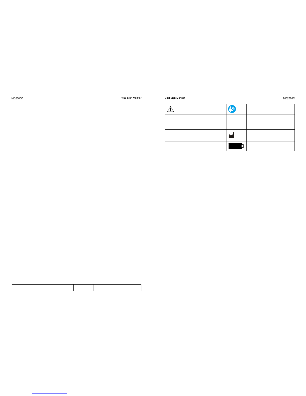
SN Serial number
Storage temperature
and humidity
Manufacturer’s
information
Data of manufacture Quantity of the battery
1.7 Product Properties
• Portable to carry, convenient to operate and easy to measure.
• 7’ TFT display screen, it can display physiology parameter, NIBP,
SpO
2
, PR, PI and PR waveform.
• Rechargeable Lithium battery
• Support external AC-adapter
things drop into the equipment, please cut off the power supply and
stop working.
• Please remove the battery, when the equipment will not be used
for a long time.
• Pull out the leads and other accessories lightly.
• All the components of this equipment, the user can be maintenance.
• This equipment don’t need to calibration.
1.4 Intended Use
Vital Signs Monitor MD2000C is a portable device indicated for
measuring physiological parameter, such as NIBP, SpO
2
, PR, PI and
PR waveform of adult and pediatric patients in hospitals, community
hospitals and medical facilities.
1.5 Electromagnetic Interference
Under the normal measuring, the equipment is not interference the
surrounding people, unit and environment. During the process of
sending data, the device interference the surrounding people, unit and
environment. If the equipment in the high-frequency electromagnetic
environment, it will do harm to the equipment, and the intended function
will failure. During the operation, you should prevent, identify and solve
the adverse electromagnetic effect. Make sure the functions of the
equipment are normal.
The reasons of the interference and solutions
• From the RF wireless module electromagnetic interference
If the interference from the RF wireless module, please replace the
equipment location.
• Direct or indirect ESD
Before use the equipment, make sure the user and the patient without
the direct or indirect ESD. The damp room can alleviate problems.
• From the radio receiver (radio or television) interference
Keep away from the interference source. If the above proposals cannot
solve the problems, please contact the consumer service center.
1.6 Symbols Denition
Symbol Denition Symbol
Denition
Page 6
6 7
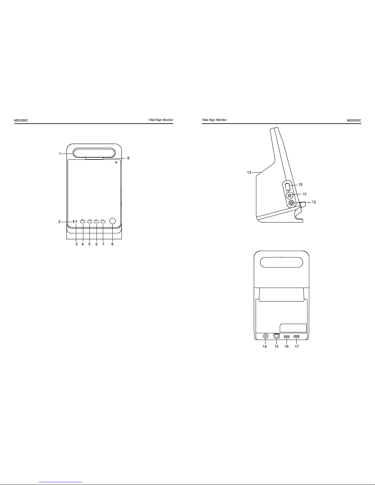
10. SpO2 interface: connect the SpO2 sensor.
11. ETCO2 interface
12. NIBP interface: connect the extended BP wires and cuff.
13. Storage space: place the accessories.
14. Power adapter socket.
CHAPTER 2 GENERAL DESCRIPTIONS
2.1 understanding the monitor
Fig.2.1
1.Integrated carry handle.
2. Power indicator light: use the AC power adapter, the light on.
3. Indicator light: turn on the device, the light on.
4. Power button: press and hold this button for 3S to power on and 4S
to turn off.
5. Alarm silence button: press the button to silence the audible alarm
for one minute.
6. Shortcut button of NIBP measuring.
7. Menu button: Press menu button enter into the setting menu.
8. Rotary Knob
The operator uses the rotary knob to select the menu item and modify
the setup. It can be rotated clockwise or counter-clockwise and pressed
like other buttons.
9. Alarm indicator light.
Page 7

8 9
Continuous ination without leakage, and the measurements display in
the device, it means the BP cuff in good condition.
Power adapter: Rightly insert the power adapter with the device, the
power indication light is on in green, it means the power adapter in good
condition.
2.5 Power off
After measurement, please take off your nger and press and hold the
power button to turn off the device.
15. Wire LAN socket.
16. USB socket.
17. USB socket.
2.2 Power supply
External AC adapter: AC-input 100-240V, 50/60Hz, 0.8A Max; DCoutput 9.0V, 3.0A
Internal battery: one piece of lithium battery, rated voltage is 7.4V,
2600mAh
The capacity of the battery will be display on the screen. It will take about
3 hours to complete charging, and then you can use about 3.5 hours.
Use the AC power supply, make sure put the device in the safety and
proper place and convenient to power off.
2.3 Charging the device
Plug the power adapter into a wall adapter, press the other end of the
power adapter into the charging port located on the back of the device,
then it becomes to charge the device. When the battery reaches 100%,
the battery indicator become fulllled. Unplug the power adapter after
nish charging.
The battery is new and fully charged; the minimum operating time of the
device is 3.5h.
The battery charge time from depletion to 90 % charge is 2.5h.
The battery charge time from depletion to 100 % charge is 3h.
2.4 Check the proper function of the device and accessories
The device: press and hold the power button for 3s, the device turn
to the normal interface, and press and hold the power button for 4s to
power off the device. It means the device in good condition.
SpO
2
probe: SpO2 probe is not wear out. Rightly insert the SpO2 probe
with the device, the red light of the SpO2 probe ash. Open the clamp,
the red light is on. After insert the nger into the SpO2 probe, the
measurements display in the device, it means the SpO2 probe in good
condition.
Thermometer: Through Bluetooth to pair the thermometer with
the device, the device displays the ear temperature. It means the
thermometer in good condition.
BP cuff: the BP cuff is not wear out. During the measurement, the device
Page 8
10 11
on the icon where the operation is wanted. Then pressing the knob,
operator will open the setup menu of the corresponding parameter so
as to set up the menu.
How to set up the parameters?
1. Rotate the knob to choose the item.
2. Press the knob into the submenu.
3. Rotate the knob to choose the item, press the knob to conrm.
4. Rotate the knob to adjust the item, press the knob to conrm.
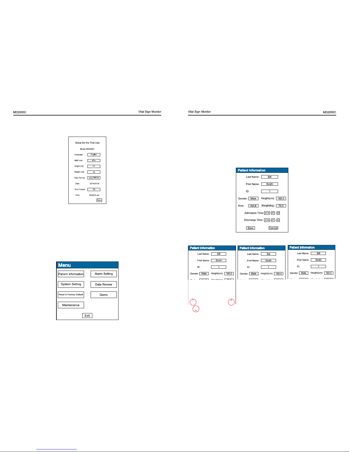
Patient information
Fig.3.3
In this submenu, fullll in the patient information.
Fig.3.4
Note:
1. Popup the keyboard when input the last name, rst name and ID.
CHAPTER 3 Setting
First time use the device, you should setup the following parameters
after turn on the device.
Fig.3.1
Language: English
NIBP unit: mmHg, kPa
Height unit: cm, in
Weight unit: kg,Ib
Date format: yyy-MM-dd, yyy/MM/dd, dd-MM-yyy
Time format: 12h, 24h
Under the measuring screen, press the menu button enter into the
setting screen.
Fig.3.2
Rotary knob is just like the cursor of computer. Operator rotates the knob
Page 9
12 13
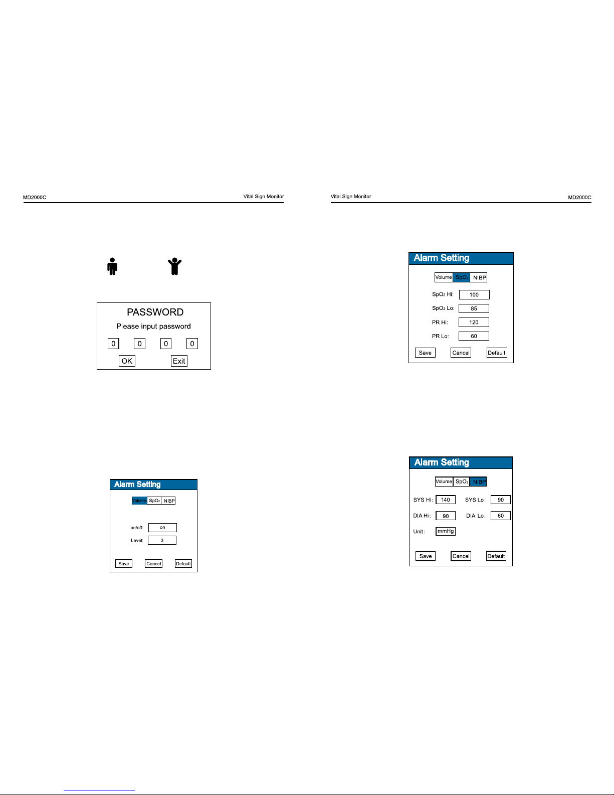
1. turn on or off the alarm.
2. Adjust the value of alarm volume, there are 5 levels, and the default
level is 3.
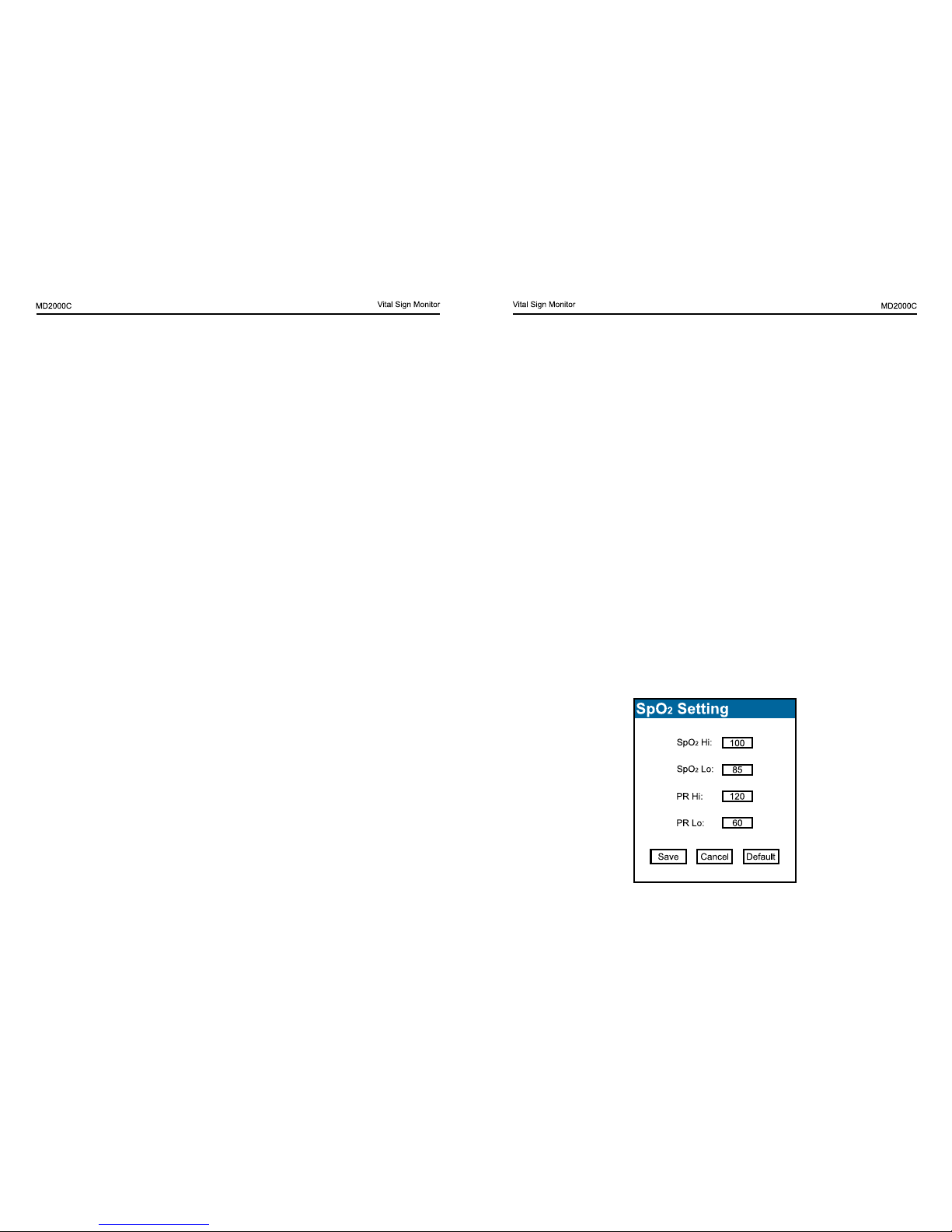
SpO
2
Fig.3. 7
High limit SpO
2
range is71mmHg ~100mmHg
Low Limit SpO
2
range is 70mmHg ~99mmHg
High Limit PR range is 31mmHg ~350mmHg
Low Limit PR range is 30mmHg ~349mmHg
Note: the low limit should less than the high limit.
NIBP
Fig.3.8
Rotate the knob to input them.
2. Rotate the knob to the shift icon (red cycle 1) then press to change
case, rotate the knob to the delete icon (red cycle 2) then press to delete
letter or number, rotate the knob to the symbol icon (red cycle 2) then
press to the symbol keyboard.
3. About the kind, adult
and Pediatric .
Alarm setting
Before setting, please enter password (2222) to set the parameter.
Fig.3.5
How do you input passwords?
1. Rotate the knob to choose the item.
2. Press the knob to conrm.
3. Rotate the knob to adjust the number 2.
4. Press the knob to conrm.
5. Repeat the step one.
Note: Every time enter into the Alarm Setting you should input the
password.
Volume
Fig.3. 6
Page 10
14 15
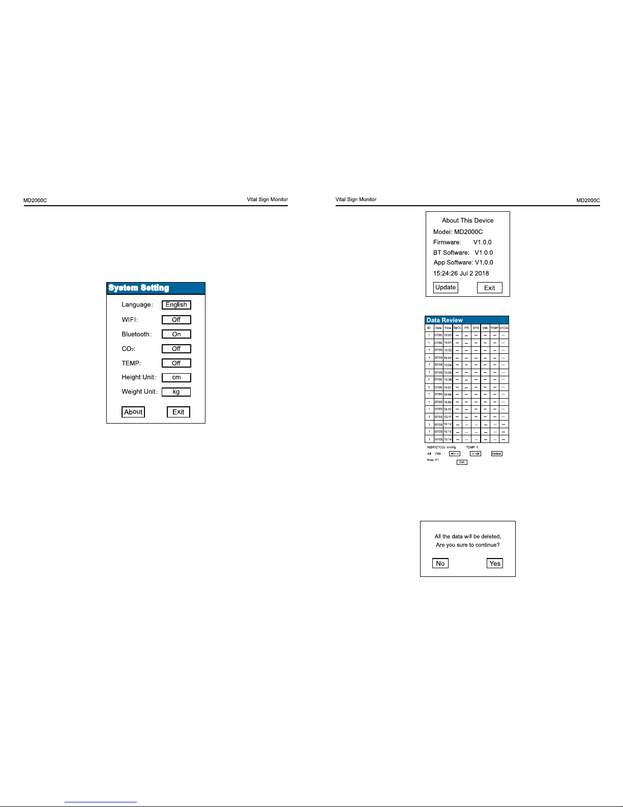
Fig.3.11
Data review
Fig.3.12
Rotate the knob on the arrow that on the bottom of the screen, press the
knob to review the records page by page.
The device can record the alarming parameter marked with red color.
Fig.3.13
High limit SYS range is 16mmHg ~ 295mmHg
Low Limit SYS range is 15mmHg ~ 294mmHg
High limit DIA range is 11mmHg ~ 285mmHg
Low Limit DIA range is 10mmHg ~ 284mmHg
Unit: mmHg / kPa
System setting
Fig.3.10
Language: English
WIFI: on / off
Bluetooth: on / off
CO
2
: on / off
TEMP: on / off
Height Unit: cm/in
Weight Unit: kg/Ib
About This Device
Under the system setting, rotate and press the knob on about to check
the device.
Page 11
16 17
CHAPTER 4 Take a measurement
4.1 Preparation
Before measuring, you connect the sensor. Please connect sensors
slightly.
Understanding the screen.
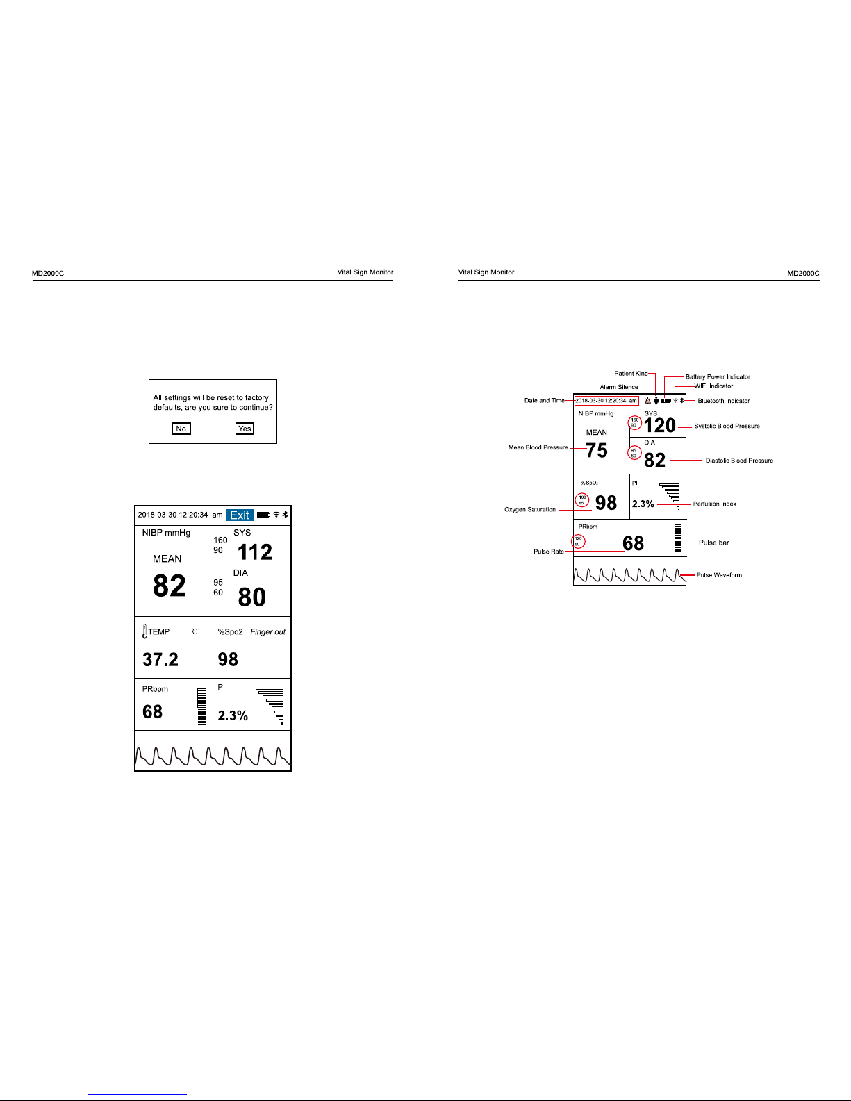
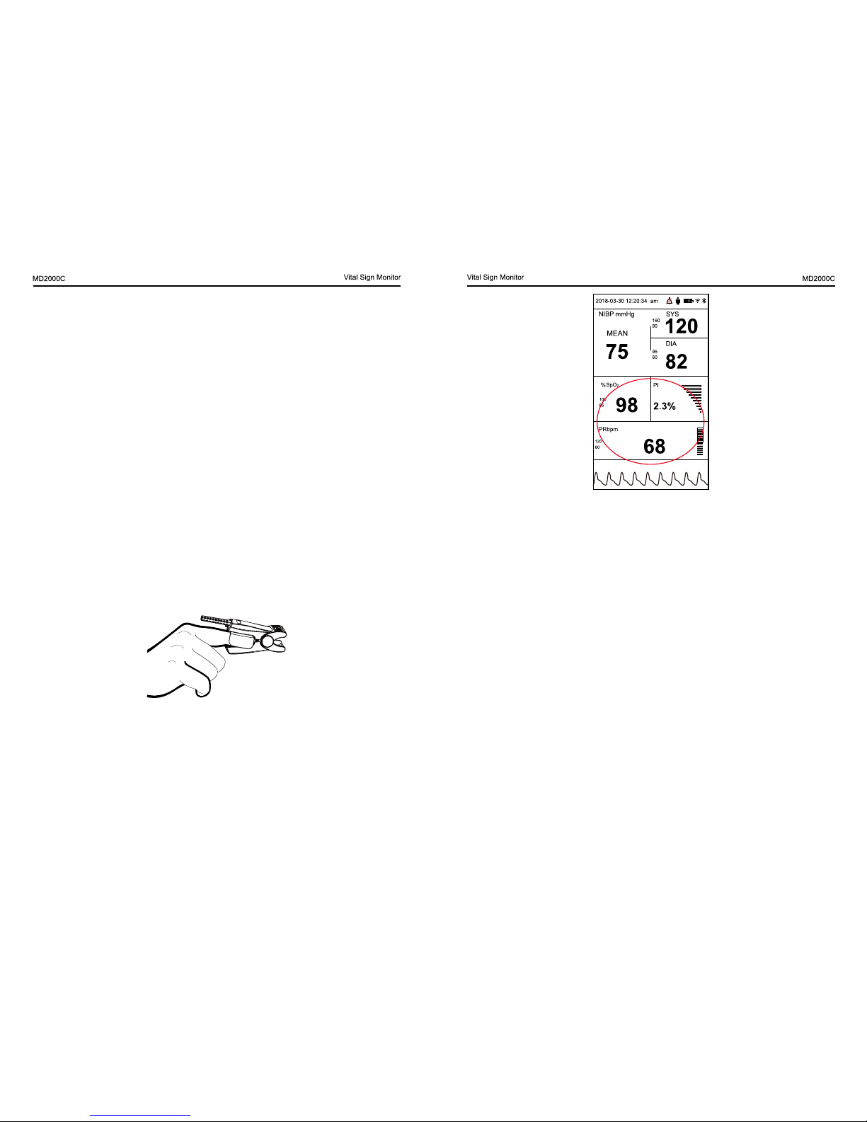
Fig.4.1
Note: In the red circle, In the red circle, there are the high and low limit
of the parameter.
Date and time
In the main screen, rotate the konb on the date and time, press the
knob enter into the time setting screen.
Under the time setting screen, rotate the konb on the time setup to
adjust the date and time.
Rotate the knob on the delete that on the bottom of the screen, press
the knob to delete data.
Please take caution to the deletion of data; you will never get the data
back once deleted.
Reset to factory default
Note: All the setting will be reset to factory defaults. Please be careful.
Fig.3.14
Demo
Rotate the konb on the demo, press the knob enter into the demo screen.
Under the demo interface, press the knob return to the menu screen.
Fig.3.15
Page 12
18 19
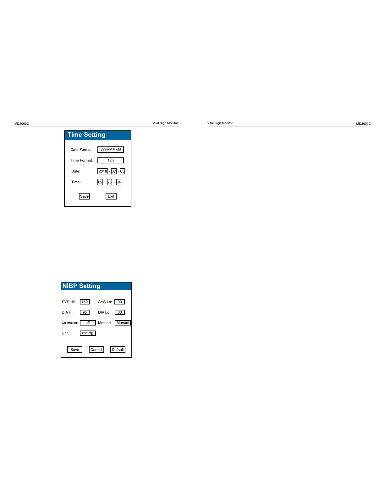
Note:
1. Remember to save the settings or you can cancel the settings.
2. Press default, all settings will be reset to factory defaults, please be
carefully.
3. Measuring method: manual or auto (1mins, 3mins, 5mins, 10mins,
20mins, 30mins, 60mins).
Warnings!
• Before starting a measurement, verify that you have selected a
setting appropriate for your patient.
• Do not apply the cuff to a limb that has an intravenous infusion
or catheter in place. This could cause tissue damage around the
catheter when infusion is slowed or blocked during cuff ination.
• Make sure that the air conduit connecting the blood pressure cuff
and the monitor is neither blocked nor tangled.
• Plug in the air hose and switch on the system.
• Too frequent measurements can cause injury to the patient due to
blood ow interference.
• Do not apply the cuff over a wound, as this can cause further injury.
• Don’t apply the cuff and its pressurization on the arm on the side
of a mastectomy.
• Pressurization of the cuff can temporarily cause loss of function of
simultaneously used monitoring device on the same limb.
• Check the operation of the Automated sphygmomanometer does
not result in prolonged impairment of the circulation of the blood
of the patient.
• Any blood pressure reading can be affected by the measurement
site, the position of the patient (standing, sitting, lying down),
exercise, or the patient’s physiologic condition.
• The performance of the automated sphygmomanometer can be
affected by extremes of temperature, humidity and altitude.
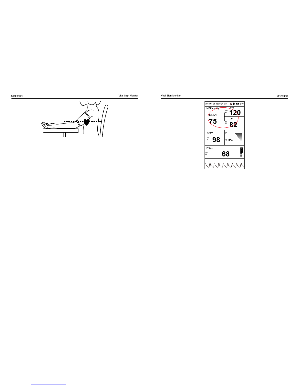
• Apply the blood pressure cuff to the patient’s arm as shown in
Fig.4.4
Fig.4.2
4.2 NIBP
Measurement Principle
This device is intended for non-invasive measuring of an adult or
pediatric ndividuals’ systolic and diastolic blood pressure using the
oscillometric method.
NIBP Setting
In the main screen, rotate the konb on the NIBP, press the knob enter
into the NIBP setting screen.
You can set the high & low limit and the unit of the NIBP.
Fig.4.3
Page 13
20 21
Fig. 4.5
WARNINGS!
• If any abnormality is observed, stop the blood pressure
measurements.
• If you suspect the accuracy of the value, please adopt other method
to further check.
• If the liquid splashes on the device or accessories, especially liquid
enter into the device, please connect the local service center.
• Inaccurate measurements may result from such causes:
a. Limb’s twitch and tremble will cause inaccuracy or prolonged the
cycling of measurement; serious tremble will lead to the failure of
measure.
b. Placing the cuff too loosely or tightly on the patient.
c. Leaky cuff or hose
d. Insure the NIBP and pulse rate within the range of this monitor.
e. Excessive patient motion will cause the inaccuracy, patient should be
relax and avoid movement.
f. Arrhythmia lead to irregular heart beat
g. Use the articial heart-lung machine
h. The patient is in shock or low temperature.
Fig. 4.4
Notes:
• Ensure that the cuff is completely deated.
• Apply the appropriate size cuff to the patient, and make sure that
the symbol “Ф” is over the appropriate artery. Ensure that the cuff is
not wrapped too tightly around the limb. Excessive tightness may
cause discoloration and eventual ischemia of the extremities.
• The width of the cuff should be either 40% of the limb circumference
or 2/3 of the upper arm length. The inatable part of the cuff should
be long enough to encircle 50~80% of the limb. The wrong size of
cuff can cause erroneous readings. If the cuff size is in question,
then use a larger cuff.
• Make sure that the cuff edge falls within the range of mark <->. If it
does not, use a larger or smaller cuff that ts better.
• Connect the cuff to the air hose. The limb chosen for taking the
measurement should be placed at the same level as the patient’s
heart. If this is not possible you should apply the following
corrections to the measured values.
• If the cuff is placed higher than the heart level, add 0.9 mmHg
(0.10kPa) for each inch of different.
• If it is placed lower than the heart level, deduct 0.9 mmHg (0.10kPa)
for each inch of different.
• The rated range of cuff pressure: 0mmhg~380mmhg.
Measuring
Press the shortcut button(NIBP) the user feel the cuff ination. After
that, the device will automatically deate. Finally, the screen will display
the results: Systolic Blood Pressure and Diastolic Blood Pressure. The
interface is as shown in Fig.4.5
Page 14
22 23
3) feet at on the oor
4) back and arm supported
5) middle of the cuff at the level of the right atrium of the heart
– a recommendation that the patient relax as much as possible and not
talk during the measurement procedure,
– a recommendation that 5 min should elapse before the rst reading
is taken;
– operator position in normal use
4.3 SpO
2, PR
and PI
What is SpO
2
Monitoring?
SpO
2
plethysmogram measurement is employed to determine the
oxygen saturation of hemoglobin in the arterial blood. If, for example,
97% hemoglobin molecules in the red blood cells of the arterial blood
combine with oxygen, then the blood has a SpO2 oxygen saturation of
97%. The SpO2 numeric on the monitor will read 97%. The SpO2 numeric
shows the percentage of hemoglobin molecules which have combined
with oxygen molecules to form oxyhemoglobin. The SpO2/PLETH
parameter can also provide a pulse rate signal and a plethysmogram
wave.
SpO
2
Setting
In the main screen, rotate the konb on the SpO
2
, press the knob enter
into the SpO2 setting screen.
You can set the high & low limit and the unit of the SpO
2
.
Fig.4.6
Pressure Safety Protection
• Automatic deation will be activated when the cuff pressure exceed
280 mmHg under the adult mode.
• Automatic deation will be activated when the continuous ination
last more than 30 seconds.
• If there is no value when measurement time exceeds 120 seconds
under the adult mode, the measurement will be canceled.
• You can press the START (NIBP) button to cancel a NIBP
measurement when necessary.
Maintenance and Cleaning
WARNINGS!
• Do not squeeze the hose of cuff.
• Do not allow liquid to enter the connector socket when cleaning
the monitor.
• Do not wipe the inner part of the connector socket when cleaning
the monitor.
• When the reusable cuff is not connected with the monitor, or being
cleaned, always place the cover on the rubber tube to avoid liquid
permeation.
NIBP cuff disinfection
The cuff can be sterilized by means of conventional autoclaving, gas,
or radiation sterilization in hot air ovens or disinfected by immersion in
decontamination solutions, but remember to remove the rubber bag if
you use this method. The cuff should not be dry-cleaned.
The cuff can also be machine-washed or hand-washed; the latter method
may prolong the service life of the cuff. Before washing, remove the
latex rubber bag, and for machine-washing, close the Velcro fastening.
Allow the cuff to dry thoroughly after washing, and then reinsert the
rubber bag.
To obtain accurate routine resting BLOOD PRESSURE measurements
for the condition hypertension including;
– adjustment of the pressure reduction rate, if applicable,
– patient position in normal use, including
1) comfortably seated
2) legs uncrossed
Page 15
24 25
Fig.4.8
Inaccurate measurements may be caused by
• Signicant levels of dysfunctional hemoglobin (such as carbonyl hemoglobin or methemoglobin);
• Intravascular dyes such as indocyanine green or methylene blue;
• High ambient light. Shield the sensor area if necessary;
• Excessive patient movement;
• High-frequency electrosurgical interference and debrillators;
• Venous pulsations;
• Placement of a sensor on an extremity with a blood pressure cuff,
arterial catheter, or intravascular line;
• The patient has hypotension, severe vasoconstriction, severe
anemia, or hypothermia;
• The patient is in cardiac arrest or is in shock;
• Fingernail polish or false ngernails;
• Weak pulse quality (low perfusion);
• Low hemoglobin;
Maintenance and Cleaning
WARNINGS!
• Disconnect the AC power before cleaning the monitor or sensor.
Note:
1. Remember to save the settings or you can cancel the settings.
2. Press default, all settings will be reset to factory defaults, please be
carefully.
Measurement principle
Principle of the oximeter is as follows: A mathematical formula is
established making use of Lambert Beer Law according to Spectrum
Absorption Characteristics of Reductive hemoglobin (RHb) and
Oxyhemoglobin (HbO2) in glow and near-infrared zones. Operation
principle of the instrument: Photoelectric Oxyhemoglobin Inspection
Technology is adopted in accordance with Capacity Pulse Scanning
and Recording Technology, so that two beams of different wavelength of
lights (660nm glow and 905nm near infrared light) can be focused onto a
human nail tip through a clamping nger-type sensor. A measured signal
obtained by a photosensitive element, will be shown on the oximeter’s
display through process in electronic circuits and microprocessor.
Measuring
a.Power on the device
b.Before starting a measurement, verify that you have selected a
suitable size sensor for the patient.
c.Connect the end of sensor to the device, the other end to the patient
measured nger, as shown in Fig.4.7
Fig.4.7
Place the measured nger into the probe. Several minutes later, the
result will display on the screen as shown in Fug.4.8
Page 16

26 27
Fig.4.9
• Do not immerse sensor completely in water, solvents, or cleaning
solutions because the sensor and connector are not waterproof.
• Do not sterilize SpO
2
sensors by irradiation, steam, or ethylene
oxide.
• Do not soak the sensor in the detergent liquid; if any abnormity of
the sensor or cable is detected, stop using it immediately.
Cleaning:
Moisten the soft cloth or gauze with alcohol and use it to wipe the surface
of sensor, and then use the clean cloth to dry it. The same method can
be used to clean the light source and photo detector.
Cables can be disinfected by 3% of hydrogen-peroxide or 7% of
isopropyl alcohol. Do not immerse the connector into the liquid.
Probe LED Specications
Wavelength Radiant Power
RED 660±3nm 3.2mw
IR 905±10nm 2.4mw
Note:
1. The pulse oximeter equpment is calibrated to display functional
oxygen saturation.
2. Pulse oximeter monitor, the pulse oximeter probe and probe cable
extender have been validated and tested for compliance with this
international standard.
3. Please use the probe and cable that provided by our company.
4. Please Verify the compatibility of the monitor, probe, and cable before
use, otherwise patient injury can result.
5. All the waveforms have been uniformed.
6. Functional tester cannot be used to assess the accuracy of a pulse
oximeter probe or a pulse oximeter monitor.
7.Alarm condition without delay, alarm signal delay, data averaging and
other signal processing have no effect of SpO
2
and PR.
Equipment data update period
As shown in the following gure. Data update period of slower average
is 8s.
Page 17

28 29
• No SpO2 wave and pulse rate display when monitoring
Check the probe connection and the nger temperature
• Cuff ination lacked when measuring blood pressure.
Cuff too loose or leak, Check the connections of tube.
• When measuring the BP, ination unnished but begin to deate.
Check the battery quantity, if the battery quantity less than 30%, please
replace the battery. If still have this problem, please check the BP cable
whether it be pressed.
5.4 Warranty and Repair
5.4.1 Warranty and repair content
• Repair response time: AM9:00 to PM17: 30 on Monday to Friday
except legal holiday.
• Repair time: AM9:00 to PM17: 30 on Monday to Friday except legal
holiday.
• Repair service: Including telephone support, eld inspecting,
ttings replacement.
• Telephone support: we can give guidance to customer’s engineer
to inspecting the instrument when you dial our service line.
Professional repair engineer online provides technical support.
• Field inspecting: we will send engineers to repair the instrument if
necessary. Certied engineers of our company or local repair team
trained by our company provide this service.
• Fittings replacement: if necessary, we will replace the damaged
ttings according to contract. The damaged ttings should be
returned to us expect for special reason.
• Spare machine for repair: it is used to replace the damaged
machine for customer using, customer should send the damaged
machine to us to repair.
• Repair for sponsoring and contributing machine: customer should
send the machine to us to repair.
• Updating software is free.
5.4.2 Exemption and restriction:
• Warranty does not apply to the damage or loss sustained due to
well-known act of god, such as re, earthquake, ood, thunder,
cyclone, hail, electrical storm, blast, building collapse, commotion,
CHAPTER 5 MAINTENANCE
5.1 Examination
Before use the device, please check the following things
• Whether the device has mechanic damage
• Check all the cables and accessories
• Check the device functions
Do not use the damage device, or it will injure the patient. Please
connect the local consumer service center. The device needs to repair
by the professional man.
5.2 Cleaning and Disinfection
Customer should responsible for periodic maintaining of the device and
its accessories. Be sure to disconnect power line to the device before
cleaning and inspecting.
Warnings!
• Do not use the strong solvents. Such as acetone.
• Do not sterilize the device using autoclaving, ethylene oxide
sterilizing.
• Before using the detergent, please follow the manufacturer’s
instructions to dilute the detergent.
• Do not use the material easy to wear. Such as steel wool and silver
polishing agent.
• Do not spray water or cleaning liquor over the product, neither
allows any liquid to ow into power switch, connector or other
intake.
• Do not leave any detergent in the surface of the device.
• The following detergent can be used:
• Ammonia (diluted)
• Sodium hypochlorite bleacher (diluted)
• Isopropyl alcohol
5.3 Troubleshooting
• No display after power on
Check the power connections, the power adapter.
Page 18

30 31
• If any code label of parts is damaged or missing, this warranty shall
become null and void. For example of code label.
5.4.5 Customer special warranty period
Due to we stipulate the warranty period according to the relevant
electronic regulation of country, which we stipulate is on year, accessory
is three months. When customer requires to extending the warranty
period, you should consider whether it is reasonable. Because electronic
product quickly replace, as to the warranty period over three years,
purchased accessories may be out of stock. In this case, we will adopt
to entirely upgrade or replace the old, you should pay the minimum
acceptable cost of renewed device.
5.4.6 Repackaging
Remove all the detectors, leads and accessories and put them into the
plastic bag.
Try to use the original packaging case and materials. Any damage due
to the improper packaging during the transportation shall be responsible
by the user.
If you are still within the period of warranty, please present the warranty
card and one copy of the invoice or receipt.
Please present a written note detailing all the troubles when repairing
the instrument.
5.4.7 Storage and Transportation
Storage: Temperature: -20℃~55℃, Humidity: ≤93%
Transportation: Transportation: via road, rail or aviation after properly
insured and packaged.
etc.
• Non-service items:
a. The cost and insurance of dismantling and testing, overhauling,
reinstall, transfer, moving the instrument or parts.
b. Damage or loss sustained due to inspected or repaired by other
institute that is not certied
c. Damage or alteration by anyone other than our company authorized
service personnel.
• The damage or lose sustained due to connection to peripheral
equipment (such as printer, computer etc.), that are not provided
by our company are not covered by the warranty.
• Obligation restriction: In the duration of warranty, if the operators
use other ttings that are not provided by us, we reserve the right
to cancel warranty.
5.4.3 Customer guarantees:
• Read the user manual in details before operation.
• Operation and maintenance according to the user manual, and
guarantee the requests of power and environment.
5.4.4 Non-warranty and Non-replacement Policy
• The work environment is not eligible. For example, if the relative
humidity exceeds 70%, circuit boards of the instrument may be
damaged due to condensate.
• If voltage of power supply is uctuant and exceeds 240VAC, the
power adapter may be damaged.
• There is smear or marks that are not belong to the instrument and
cannot be removed from the outside surface of the instrument.
• The instrument or its ttings are mechanically damaged.
• The circuit is short and damaged due to liquor or other stuff ow in
the instrument or its ttings.
• All probe and its accessories are not free replacement.
• Leakage of air cell of blood pressure sleeve due to improper
storage or operation is not free replacement.
• The malfunction with result from improper repair by anyone other
than our company authorized service personnel.
• The malfunction with result from improper use.
Page 19
32 33
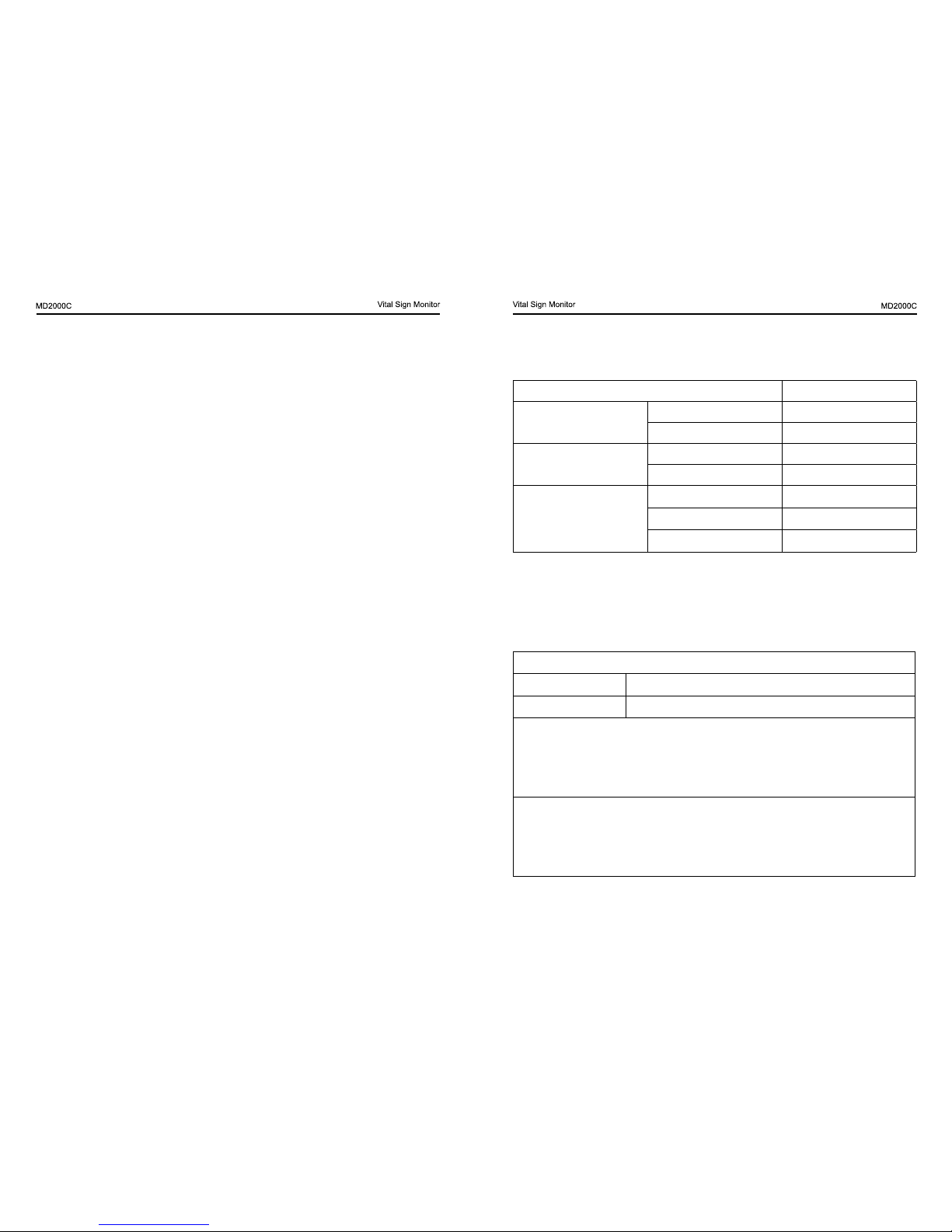
Measurement range:70~100%
Resolution:1%
Accuracy:
Classication Accuracy
no motion
Adults ±2%
Pediatrics ±2%
motion
Adults ±3%
Pediatrics ±3%
Low Perfusion
Adults ±2%
Pediatrics ±2%
Neonates ±3%
PR
Measurement range: 30bpm~250bpm
Resolution:1bpm;
Accuracy:±2bpm or ±2% (no motion), ±3bpm(motion/ Low PI)
Alarm
Blood Pressure
Systolic/default upper limit:160 mmHg,lower limit:90mmHg
Diastolic/default upper limit:95 mmHg,lower limit:60mmHg
Systolic: upper limit:16mmHg~295mmHg,
lower limit:15mmHg~294mmHg
Diastolic:upper limit:11mmHg~285mmHg,
lower limit:10mmHg ~284mmHg
PR
Default: upper limit:120bpm,lower limit:50bpm
upper limit:11bpm~235bpm
lower limit: 10bpm~234bpm
CHAPTER 6 SPECIFICATIONS
NOTES:
• Specications may be changed without prior notice.
• The circuit diagrams, the list of components, the illustration of
diagrams, and the detailed rules of calibration, are provided
exclusively to professional personal authorized by our company.
• The illustrations used in this manual may differ slightly from the
appearance of the actual device.
• The maximum application time for each type of probe at a single
site is 4h.
• The equipment has been calibrated, users do not to calibrate. In
order to ensure the accuracy of the probe, please change the probe
once a year. Make sure that the type of probe need to be specied.
• The equipment is guaranteed for 5 years from the date of purchase.
• Please take attention that changes or modication not expressly
approved by the party responsible for compliance could void the
user’s authority to operate the equipment.
Display
The screen dimension: 7inch
The screen resolution: 800×480
The device dimension: 292mm ×168mm × 148mm (±5mm)
Displayed parameters: Patient information, NIBP (systolic and diastolic),
TEMP, %SpO
2
, PR, PI and PR waveform.
NIBP
Measuring range:
Systolic 60mmHg ~ 255mmHg
Diastolic 30mmHg ~ 195mmHg
Resolution:1mmHg
Accuracy: Max.±3 mmHg
Maximum standard deviation: 8 mmHg
Measuring mode: manual / auto (1 minutes, 3 minutes, 5 minutes, 10
minutes, 20 minutes, 30 minutes, 60 minutes)
SPO
2
Page 20
34 35
SpO
2
Default: upper limit:100%,lower limit:85%
upper limit:86%~100%,continuously adjust, step: 1%
lower limit:85%~99%,continuously adjust, step: 1%
Note: the upper limit must greater than the lower limit.
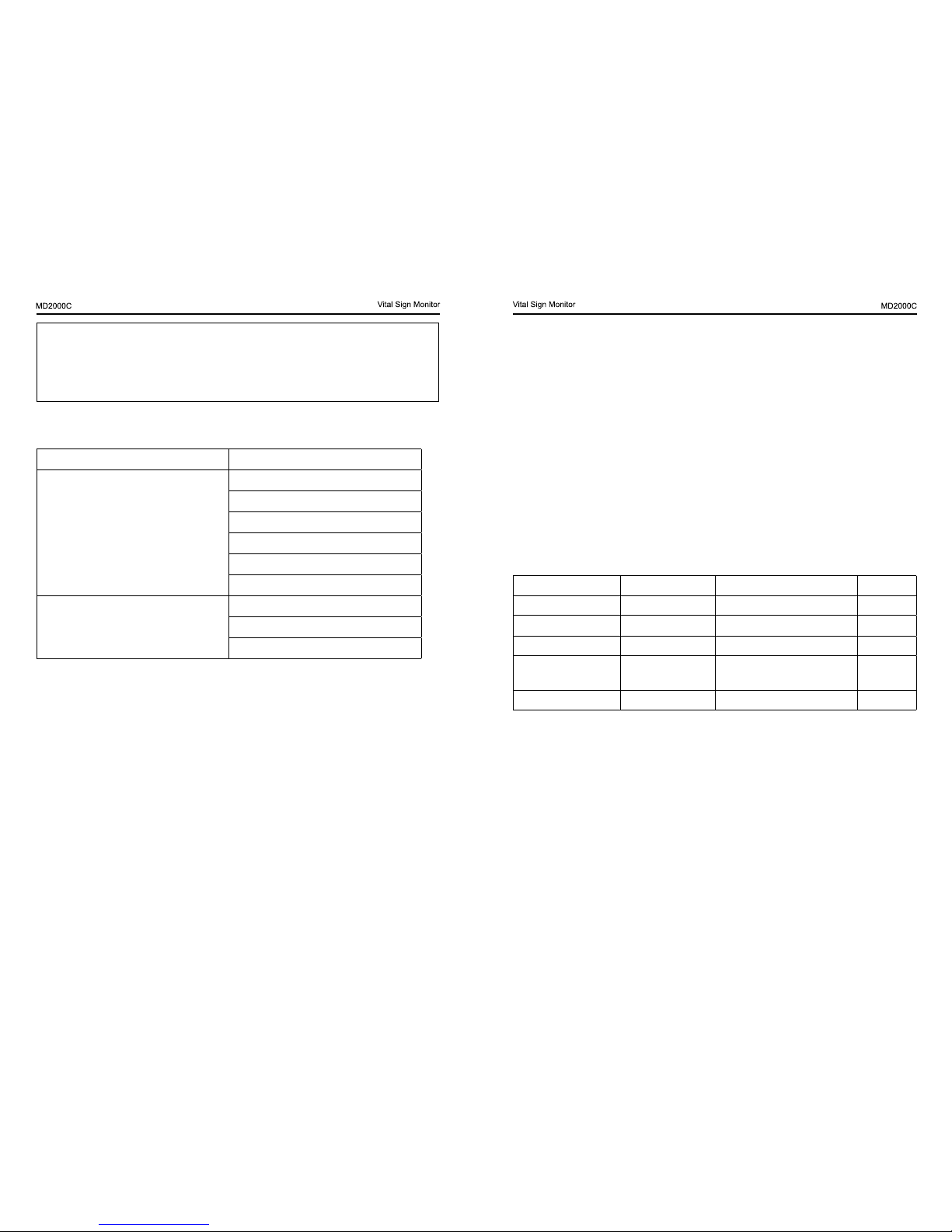
Alarm level
High(Level 1) SpO2 exceeds the limit
Medium(Level 2)
BP exceeds the limit
HR exceeds the limit
Systolic exceeds the limit
Diastolic exceeds the limit
Mean exceeds the limit
The battery less than 5%
Low(Level 3)
SpO
2
probe off
No nger
error measurement of BP
Environment Requirements
Operation Temperature: 5℃~40℃
Storage/ Transport Temperature: -20℃~+55℃
Ambient Humidity: ≤80% no condensation in operation; ≤93% no
condensation in storage/transport
Atmosphere pressure: 86kPa~106kPa
Power supply
DC7.2V/2600mAh, one rechargeable lithium battery
Operating time: 24 hours continuous working
power adapter: MENB1030A0900F02; Output: 9V DC, 3A
Fuse
3A/32V
Classication
According to the type of protection against electric shock: internal
powered equipment.
According to the degree of protection against electric shock: type BF
applied part
According to the degree of protection against dust and water: IP22
According to the mode of operation: continuous operation
Applied part
SpO
2
probe
Temperature probe
NIBP cuff
Note: All the applied part contains temperature probe, cuff, electrode
plate and SpO
2
probe are compliance with the biological compatibility
Standard.
List of accessories
Accessories Mode Type Quantity
SpO
2
probe M-50E013CS09 9 pin(DB9), 0.9m 1 piece
NIBP cuff for adult RNC0001A-013B 27CM-35CM 1 piece
NIBP cuff for infant CM1202 18CM-26CM 1 piece
Power adapter LXCP30-009A Input: 100 – 240V AC 0.8A;
Output: 9V DC, 3A
1 piece
User manual 1 piece
FCC declaration
This device complies with Part 15 of the FCC Rules. Operation is subject
to the following two conditions:
(1) This device may not cause harmful interference, and
(2) This device must accept any interference received, including
interference that may cause undesired operation.
Attention that changes or modication not expressly approved by the
party responsible for compliance could void the user’s authority to
operate the equipment.
Note: This product has been tested and found to comply with the limits
for a Class B digital device, pursuant to Part 15 of the FCC Rules. These
Page 21
36 37
limits are designed to provide reasonable protection against harmful
interference in a residential installation. This product generates, uses,
and can radiate radio frequency energy and, if not installed and used
in accordance with the instructions, may cause harmful interference to
radio communications. However, there is no guarantee that interference
will not occur in a particular installation. If this product does cause harmful
interference to radio or television reception, which can be determined by
turning the equipment off and on, the user is encouraged to try to correct
the interference by one or more of the following measures:
—Reorient or relocate the receiving antenna.
—Increase the separation between the equipment and receiver.
—Connect the equipment into an outlet on a circuit different from that to
which the receiver is connected.
—Consult the dealer or an experienced radio/TV technician for help.
CHAPTER 7 Compliance Information for EMC Test
Electromagnetic emission
Emission test Compliance Electromagnetic Environment – guidance
Conducted and radiated
RF emissions
Group 11, Group 1,
Class B
Home Healthcare environment
Electromagnetic immunity
Immunity test IEC 60601 test level Compliance Level
Electromagnetic
Environment –
guidance
Electrostatic
discharge (ESD) IEC
61000-4-2
± 8kV contact
±15kV air
± 8kV contact
±15kV air
Special healthcare
environment
The relative humidity
should be at least 50%.
Radiated RF
IEC 61000-4-3
10 V/m
80 MHz to 2.7 GHz
10 V/m
80 MHz to 2.7 GHz
Home healthcare
environment
Power
frequency (50/60Hz)
magnetic eld
IEC61000-4-8
30A/m 30A/m
Home healthcare
environment
Electromagnetic immunity to RF wireless communications equipment
Test
frequency
(MHz)
Band
a
)
(MHz)
Service
a
) Modulation b)
Maximum
power
(W)
Distance
(m)
Immunity test
level
(V/m)
385 380-390 TETRA 400
Pulse
modulation
b
)
18Hz
1.8 0.3 27
450 430-470
GMRS 460,
FRS 460
FM
c
)
±5kHz
deviation
1kHz sine
2 0.3 28
Page 22

38
710
704-787
LTE Band
13,17
Pulse
modulation
b
)
217Hz
0.2 0.3 9745
780
810
800-960
GSM
800/900,
TETRA 800,
iDEN 820,
CDMA 850,
LTE Band 5
Pulse
modulation
b
)
18Hz
2 0.3 28
870
930
1720
1700-
1990
GSM 1800;
CDMA
1900;
GSM 1900;
DECT;
LTE Band
1,3,4,25;
UMTS
Pulse
modulation b)
217Hz
2 0.3 281845
1970
2450
24002570
Bluetooth,
WALN,
802.11
b/g/n, RFID
2450, LTE
Band
7
Pulse
modulation b)
217Hz
2 0.3 28
5240
51005800
WLAN
802.11
a/n
Pulse
modulation b)
217Hz
2 0.3 95500
5785
Manufactured for:
Beijing Choice Electronic Technology Co., Ltd.
Room 4104, No. A12 Yuquan Road
Haidian District
100143 Beijing
PEOPLE’S REPUBLIC OF CHINA
 Loading...