

Page 1

BEIJING CTB SERVO CO., LTD.
Address: Wanggezhuang Industry Base, Shilipu Town, Miyun County,
Beijing
Tel.: 010 -82755611
Fax: 010 -82755610
24-hour national free service Tel.: 400 -888-9055
Data No.: ZL-14-808-IBCN
The data may subject to change without notice as improvement of
the product.
CTB TECHNOLOGY
Distributor
Page 2

BEIJING CTB SERVO CO.,LTD.
Data No.: Z L-14-808-I B C N
GH DRIVER
Operating manual
AC servo driver
Model: BKSC-□ □ □ □ GHX
Class 400V, 1.5 ~ 315KW (2.5 ~ 460KVA)
Please send the manual to final user, and keep it properly.
CTB TECHNOLOGY
Page 3

GH DRIVER CTB
Preface
Thank you for purchasing GH series servo driver produced by Beijing CTB Servo Co., Ltd. The GH
series AC servo driver is a high-quality, multi-functional and low-noise AC servo driver that was
researched, developed and manufactured by Beijing CTB Servo Co., Ltd. The driver is servo driver for
AC induction motor (IM) and AC permanent magnet synchronous motor (PM). It can control the position,
speed, acceleration and output torque of various AC servo motor appropriately.
In command to achieve control functions of various machine tools, GH series AC servo driver is
equipped with dual 32-bit CPU and abundant control function module. It can be conveniently connected
with various domestic and foreign CNC systems through standard control interfaces to allow full play for
function of CNC system. The characteristics of torque, acceleration and deceleration, precision and
efficiency of machine tool which is equipped with GH series AC servo driver are remarkable, and
accurate stop, C-axis, rigid tapping, electronic shift, multi-axis synchronization and other functions can
be realized easily.
As the first choice of driving product of various machine tool power shaft, GH series AC servo driver can
be widely used for drive of product such as CNC milling machine, vertical machining center, horizontal
machining center, CNC boring machine, CNC lathe, vertical lathe, heavy horizontal lathe and gantry
machine tool.
For proper application, please read the manual carefully before using the GH series AC servo driver.
Abnormal operation, fault or reduction of service life, and even personal injury accident may be caused
by inappropriate use. Therefore, the manual shall be read repeatedly before use, and operate in strict
accordance with the instructions. The manual is attachment with the equipment. Please keep it properly
after using for future repair and maintenance of the driver.
01
Page 4
CTB GH DRIVER
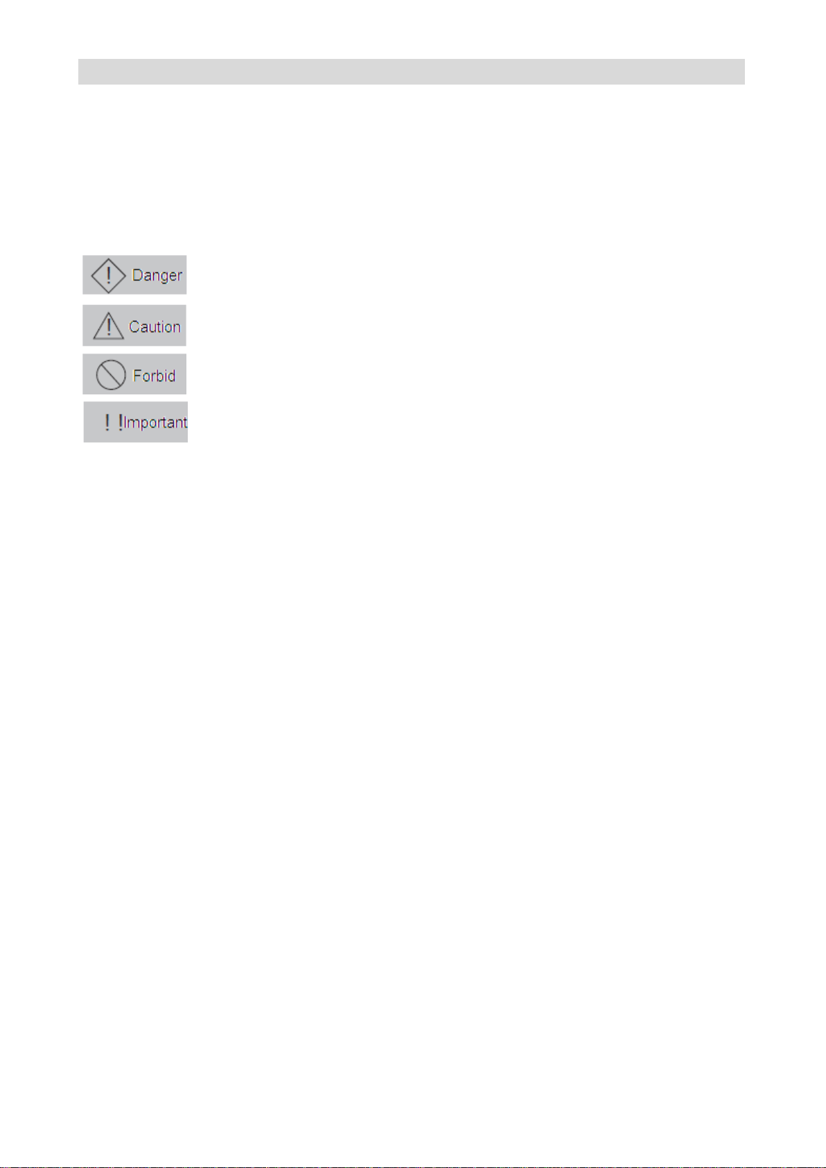
Use the symbol where danger, even personal injury or death when wrong about the
described content.
Use the symbol where danger, even mild or moderate personal injury and
equipment damage when wrong about the described content.
Prohibited matters (matters that cannot do).
Certain matters do not belong to "danger", and "caution", but they are required to
be abided by user. They are marked in the relevant sections.
Safety -related symbol description
The following symbols are used for safety-related content in the manual. Sentences marked by the
safety symbols describe important content, and must be abided. If the requirements in the safety-related
content are not abided, application of the product may lead to abnormal product operation, damage to
the product, even danger and personal injury.
Page 5
GH DRIVER CTB
Caution
● For risk of injury, please do not install damaged or part missing driver.
Caution
● For risk of fire, please install the equipment on nonflammable metal plate without combustible
materials around.
● Please be sure to tighten the mounting screws of the driver. Falling and damage of the driver or
personal injury may be caused by mounting screws loosing.
●Please do not install the equipment in environment with flammable gas where an explosion is
caused easily.
Danger
● For risk of electric shock and fire, please make sure that the input power supply is in the OFF state
before wiring.
●For risk of electric shock, the operation on main circuit terminal of the controller shall be conducted
after the power is cut off for five minutes, and the power charge indicator CHARGE in the controller
completely extinguished.
●For risk of electric shock and fire, the wiring shall be carried by professional electrical engineering
personnel.
●For risk of electric shock and fire, the ground terminal must be grounded reliably. (earth resistance
shall be lower than 4Ω)
● It's prohibited to directly connect terminals of P / PB and N, or connect the zero line or the earth
wire to the N terminal. Otherwise, the rectifier bridge will be shorted and the main loop will be burned.
●It's prohibited to connect the high-voltage line to control terminal of the driver. Otherwise, the control
board will be burned.
●For risk of injury, please set emergency stop and locking circuit at the outside of the controller (user
is responsible for the wiring) .
● There is a risk of electric shock and short circuit.
Caution
●For risk of injury and fire, please ensure that the voltage of the main circuit AC input power and the
Safety precautions
◆ Unpacking inspection
◆ Installation
◆ Wiring
◆ Wiring
03
Page 6
CTB GH DRIVER
rated voltage of the driver are consistent.
● Please do not conduct withstand voltage and insulation test to the controller arbitrarily. Otherwise,
the semiconductor and other components in the controller may be damaged.
●For risk of fire, please connect braking resistor and braking unit according to the wiring diagram.
● Please do not connect the AC input power cord to the output U, V, W terminals. Otherwise,
damage to inside of the controller may be caused.
●For risk of fire and malfunction of the controller, please tighten the terminals of main loop and
control circuit with appropriate torque.
●Please do not connect the phase shifting electrolytic capacitor and LC / RC noise filter to the output
circuit. Otherwise, damage to inside of the controller may be caused.
●Please do not connect the electromagnetic switch and electromagnetic contactor to the output
circuit to connect or disconnect the load. During loaded operation of the controller, the surge current
will cause protection circuit action of the controller.
Danger
●For risk of electric shock and short circuit, please do not touch the terminals of the main circuit
directly after power-on.
●Please confirm the input and output signals to guarantee safe operation. Malfunction of the system
will cause casualties and damage to the work piece and nearby equipment..
●For risk of injury, alarm reset only can be done after ensuring that the operating signal is cut off.
Alarm reset with operating signal will lead to suddenly re-start.
●For risk of driver burning, the inside of long term stored driver shall be checked for water and
condensation.
●For risk of electric shock and burning the equipment, it's prohibited to touch the terminals of the
driver with hand during operating.
Caution
●For risk of scalding, the running servo driver and motor may have a high temperature rise, please do
not touch.
●For risk of scalding and electric shock as the braking resistor has a high temperature rise for
discharging, please do not touch.
●For risk of damage to the equipment and accident, please do not change the settings of the drive
arbitrarily.
Danger
◆ Trial run
◆ Maintenance and inspection
Page 7
GH DRIVER CTB
●For risk of electric shock, please do not directly touch terminals of the controller. Some of them
have high voltage and very dangerous.
●For risk of electric shock, please do install the housing before power-on; and must disconnect the
power firstly before removing the housing.
●For risk of electric shock and fire, please confirm that the power source is in the OFF state or not
before wiring.
● Inspection and maintenance only can be carried out after cut off the main circuit input power and
confirm that the power charge indicator CHARGE completely extinguished. There is a risk of
electric shock as residual power in electrolytic capacitor.
●Please make designated professional electrical engineering personnel to conduct inspection and
maintenance. Before work, please take off metal object (watch, rings etc.), and use tools with
insulation protection during operation. Otherwise, it may cause electric shock.
●For risk of explosion and fire, used battery, circuit printing plate must not be throw into fire.
Otherwise, it may cause explosion.
Caution
●CMOS IC integrated circuit is installed on main control panel. Full attention shall be paid during
operating. The electrostatic induction due to direct touching of finger on the main control panel may
cause damage to the main control panel.
●For risk of electric shock, please do not conduct wiring and removing terminal when the equipment
is energized.
●For risk of damage to the equipment, the appropriate parameter settings must be carried out
before running after control panel replacing.
05
Page 8

CTB GH DRIVER
Table of contents
Preface………………………………………………………...……………………………………1
Safety -related symbol description………………………..…………………………………..2
Safety precautions……………………………………………..…………………..……………..3
Chapter 1 - Installation…………………………………………..………………………….…1-1
Introduction to GH DRIVER…………………………………..…………………………………1-2
Unpacking inspection…………………………………………..………..………………………1-3
Standard specifications and performance parameters………………………….……………1-4
Driver nameplate description……………………………………………………………………1-5
External dimensions and installation dimensions……………………………………….……1-5
Confirmation and requirements of the installation space……………………………………1-8
Notes on motor and load…………………………………………………………………..……1-8
Notes on the driver………………………………………………………………………………1-9
Notes on scrapping………………………………………………………………………..……1-10
Chapter 2 – wiring……………………………………………………………………...……….2-1
Selection and connection of peripheral devices……………….……………………...………2-2
Wiring of the main circuit terminals……………………………………………………………2-3
Wiring of control circuit ……………..…………………………………………………………2-11
Connection of the encoder interface…………………………………………………………2-20
Connection of the serial communication port ………………………………………………2-21
Chapter 3 - Manipulator application…………………………………………..…………….3-1
Digital tube display 0.4 ~ 18.5kw driver:
Configuration and key functions of the manipulator…………………………………………3-2
Operative mode of the driver……………………………………………………………………3-3
Operative mode of the manipulator……………………………………………………………3-4
Use method of the manipulator………………………………..………………………………3-4
Modify the parameters with the manipulator…………………………………………………3-5
Monitor operating state with the manipulator………………….………………………………3-5
Digital tube display 22 ~ 315kw driver:
Configuration and key functions of the manipulator…………………………………………3-6
Operative mode of the driver………………………………….……….………………………3-8
Operative mode of the manipulator…………………………………….………………………3-8
Page 9

GH DRIVER CTB
Use method of the manipulator………………………………...……….………………………3-9
Modify the parameters with the manipulator…………………….…….………………………3-9
Monitor operating state with the manipulator……………………….………………………3-10
Liquid crystal display 0.4 ~ 18.5kw driver:
Configuration and key functions of the manipulator…………………………………………3-11
Operative mode of the driver……………………………………….….………………………3-12
Operative mode of the manipulator………………………………….………………………3-12
Use method of the manipulator……………………………….……….………………………3-13
Modify the parameters with the manipulator……………….……….………………………3-13
Monitor operating state with the manipulator…………………….…………………………3-14
Liquid crystal display 22 ~ 315kw driver:
Configuration and key functions of the manipulator…………………………………………3-15
Operative mode of the driver………………………………………….………………………3-17
Operative mode of the manipulator………………………………..….………………………3-17
Use method of the manipulator…………………………………….….………………………3-18
Modify the parameters with the manipulator……………………….………………………3-18
Monitor operating state with the manipulator………………………...………………………3-19
Chapter 4 - Test run…………………………………………………………………..………..4-1
Basic procedure of test run………………………………………..……………………………4-2
Confirmation of connection of the main circuit………………………………………………4-2
Control circuit wiring confirmation……………………………………………………………4-3
Initial power-on of the driver……………………………………….……………………………4-3
Motor and driver parameters confirmation……………………………………………………4-3
No-load test run……………………………………………………..……………………………4-4
Loaded test run……………………………………………………..……………………………4-4
Chapter 5 - Parameter list……………………………………………………………………5-1
Hierarchical structure diagram of display function of the manipulator .............................5-2
Monitor parameter Un........................................................................................................5-3
Application parameter An...................................................................................................5-9
Chapter 6 – Setting parameters by function………...………………..……………………6-1
Analog speed control……………………………………………..……………………………..6-2
Pulse speed control……………………………………………...………………………………6-4
07
Page 10

CTB GH DRIVER
Analog rigid tapping…………………………………………….………………………………6-6
Pulse rigid tapping/pulse position …………………………….……………………….…….. 6-7
Orientation……………………………………………………………………….. ………………6-8
Swing……………………………………………………………….……….. …………………6-10
Operation panel operation ……………………………………………….. …………………6-12
modbus communication settlement …………………………………….. …………………6-12
Chapter 7 – PLC functions introduction…………………………………………………..7-1
Introduction to system software resourse ……………………………………………..……..7-2
PLC CAN communication …………………………….………………………………………..7-3
PLC modbus communication ………………….…………………………………………..…..7-5
Pmotion program software description …………….………………………………………..7-6
Speed control …………………………………….……………………………………..……..7-8
Positioning control …………………………….……………………………………………..7-11
Pulse position synchronization control…………….………………………………………..7-13
Position limit and restoration……………………….………………………………………..7-14
Chapter 8 – Troubleshooting………………………………………………………………..8-1
List of fault alarm and remedies ………………………………………………………………..8-2
Common fault analysis……………………………….………………………………………..8-4
Alarm reset method……………………………………….....………………………...………..8-7
Chapter 9 - Routine maintenance...................................................................................9-1
Prompt...............................................................................................................................9-2
Routine maintenance .......................................................................................................9-2
Regular maintenance.......................................................................................................9-3
Wearing parts of the driver .............................................................................................9-3
Driver storage..................................................................................................................9-4
Driver warranty.................................................................................................................9-4
Page 11
GH DRIVER CTB
Installation
The chapter describes matters to be confirmed and installation requirements for the user
after getting the GH DRIVER.
Introduction to GH DRIVER…………………………………….…..………………………….1-2
Unpacking inspection………………………………..…………………………………….……1-3
Standard specifications and performance parameters…..………………………………..…1-4
Driver nameplate description……………………….………..……………………………..…..1-5
External dimensions and installation dimensions.………..........................................……..1-5
Confirmation and requirements of the installation space.….………………………………...1-8
Notes on motor and load…………………………….……………………………………….….1-8
Notes on the driver…………………………….……………..……………...…………………..1-9
Notes on scrapping………………………….……………………………..…………………..1-10
Page 12
CTB GH DRIVER
Code
Item
Description
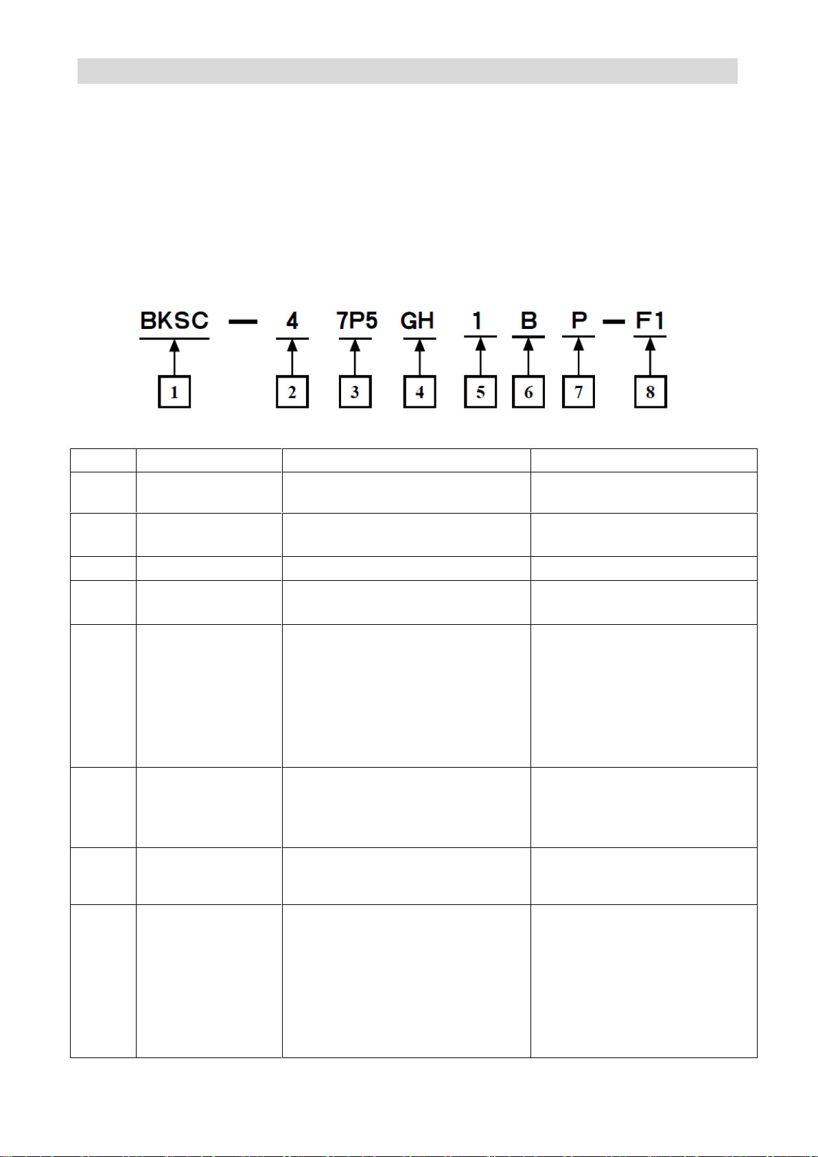
Illustrated model meaning
1
Manufacturer code
BKSC: code for driver product of the
manufacturer
Manufactured by BEIJING CTB
SERVO CO., LTD.
2
Voltage level
2: level 200V
4: level 400V
level 400V
3
Power code
See power code list for detail
7.5kW
4
Product series
GS: GS series driver
GH: GH series driver
GH series driver
5
Encoder model
None: incremental 10 driver
0:without encoder
1: incremental encoder
2: rotary transformer
3: Sin-Cos encoder
4: absolute value encoder
5: magnetic encoder
incremental encoder
6
Product model
None: standard type
(CP1000A1/C1)
B: general type(CP1000B1/D1)
T:special type (CP1000AT1/CT1)
general type(CP1000B1)
7
Production
upgrading
identification
None: conventional design
P: new energy-saving design
new energy-saving design for
main board of the driver
8
Non-standard
identification
None: standard product
F1: Non-standard requirements to
main board
F2: Non-standard requirements to
driver
F3: Non-standard requirements to
housing
Other: special customer
Non-standard requirements to
main board of driver
Introduction to GH DRIVER
GH DRIVER is a type of driver that specifically designed for machine tool. Precise control of position,
speed, acceleration and output torque of AC induction servo motor and AC inverter motor is allowed
through the driver. It can be used for control of motor of machining center, CNC milling machine, CNC
drilling machine, CNC lathe, CNC grinder, and feed motor of large gantry equipment and vertical lathe.
To achieve the best operation effect, please complete wiring with CNC system by the " CTB servo
application manual ", and carry out installation and commissioning in accordance to the manual.
Model description (taking 7.5kW as example)
Table 1-1 Detailed description of motor model designation
Page 13
GH DRIVER CTB
Driver model
Rated
capacity(KVA)
Rated input
current (A)
Rated output
current (A)
Adapt motor
power (kW)
Built-in
brake unit
BKSC-41P5GHX
2.5 4 3
1.5
Yes
BKSC-42P2GHX
3 6 5
2.2
Yes
BKSC-43P7GHX
5.5 9 8
3.7
Yes
BKSC-45P5GHX
8.5
14.2
13
5.5
Yes
BKSC-47P5GHX
11
18
17
7.5
Yes
BKSC-4011GHX
17
26
25
11
Yes
BKSC-4015GHX
21
35
32
15
Yes
BKSC-4018GHX
24
38.5
37
18.5
Yes
BKSC-4022GHX
30
46.5
45
22
Yes
BKSC-4030GHX
40
62
60
30
Yes
BKSC-4037GHX
50
76
75
37
Yes
BKSC-4045GHX
60
92
90
45
Yes
BKSC-4055GHX
72
113
110
55
Yes
BKSC-4075GHX
100
157
152
75
Yes
BKSC-4090GHX
116
190
185
90
Yes
BKSC-4110GHX
138
236
230
110
Yes
BKSC-4132GHX
167
288
280
132
Yes
BKSC-4160GHX
200
345
336
160
Yes
BKSC-4200GHX
250
420
370
200
No
BKSC-4250GHX
300
530
460
250
No
BKSC-4315GHX
360
680
570
315
No
Confirm item
Confirm method
Confirm that the materials listed on the packing
list are complete.
Check the materials in the packing against the
packing list stuck to the external packing.
Are they in line with the ordered merchandise?
Please confirm the label at the side of the driver.
Is there any damage?
Check the overall appearance for damage during
transportation.
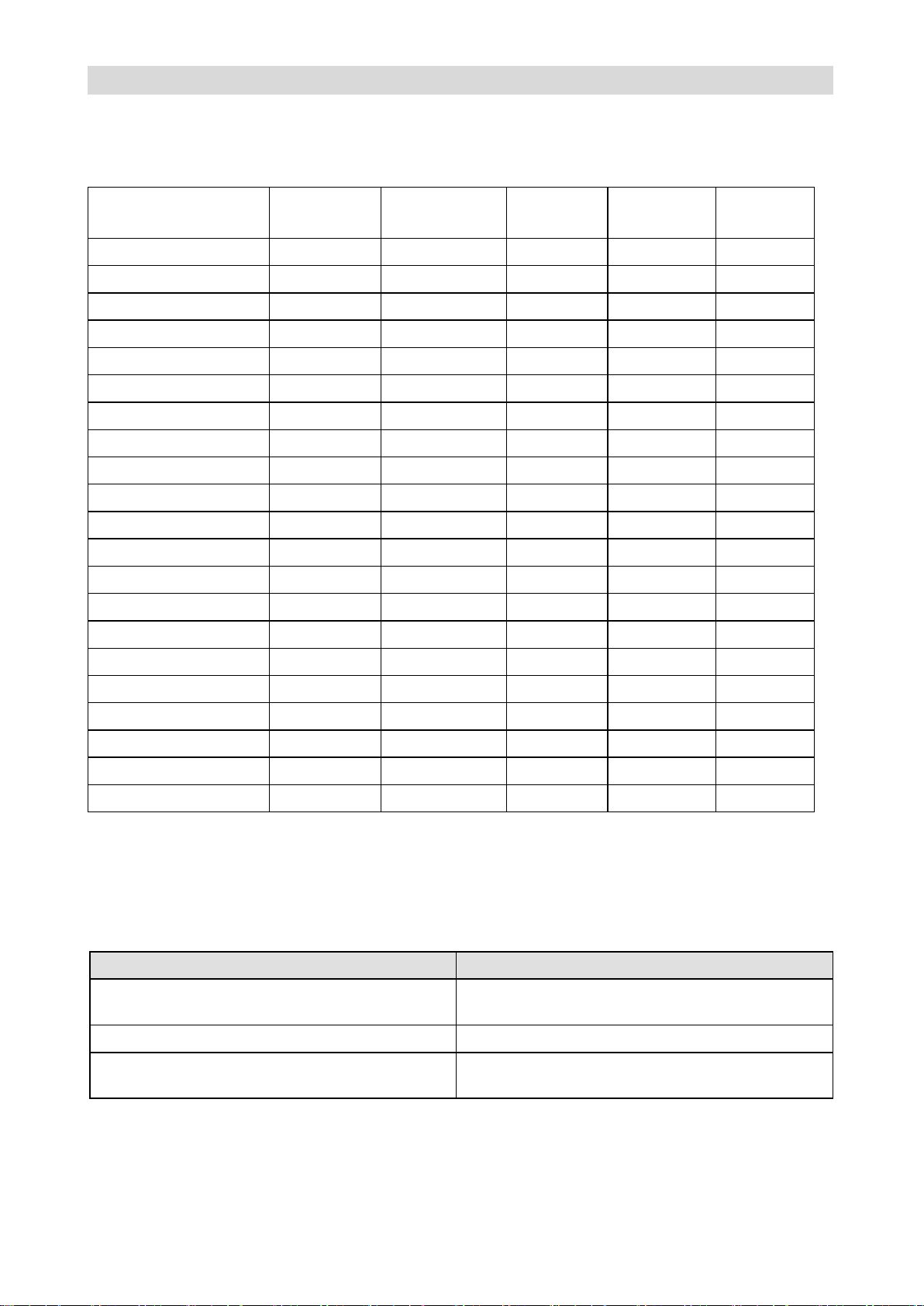
● GH DRIVER series applies for 21 types with a motor capacity of 1.5kW to 315kW. Please
see table 1-2 for detail
Table 1-2 GH DRIVER model (rated voltage: 400v)
Unpacking inspection
Please confirm the following items when you get the product. Please contact directly with the dealer or
manufacturer that purchased from for any adverse situation. Please see Table 1-3 for detail.
Table 1-3 Confirm items
Page 14

Page 15
GH DRIVER CTB
Model BKSC-××××GHX
41P5
42P2
43P4
45P5
47P5
4011
4015
4018
4022
4030
4037
4045
4055
4075
4090
4110
4132
4160
4200
4250
4315
Adapt motor power kW
1.5
2.2
3.7
5.5
7.5
11
15
18.5
22
30
37
45
55
75
90
110
132
160
200
250
315
Output
Capacity KVA
2.5 3 5.5
8.5
11
17
21
24
30
40
50
60
72
100
116
138
167
200
250
300
360
Current A
3 5 8
13
17
25
32
37
45
60
75
90
110
152
185
230
280
336
370
460
570
Maximum output
voltage V
3-phase 380/400/415/440V corresponding input voltage
Maximum output
speed rpm
4-pole motor 15000rpm: 500Hz
Power
Rated voltage and
frequency
3-phase 380/400/415/440V: 50/60Hz±5%
Allowed voltage
pulsation
+10%, -15%
Control characteristics
Control mode
Sine wave PWM modulation, entirely closed-loop vector control
Torque feather
200% rated torque output below the fundamental frequency. Accuracy: ±5%
Range of speed
regulation
1: 15000
Speed control
accuracy
±0.1%
Frequency set
resolution
Digital quantity: : 0.01Hz; Analog: Unipolar, maximum output frequency is /4092; bipolar, maximum output frequency is / 2046
Position control
accuracy
±1PULSE
Acceleration
0.05~3000Hz/s
Brake mode
dynamic braking. 125% rated torque: built-in braking unit (external braking resistor)
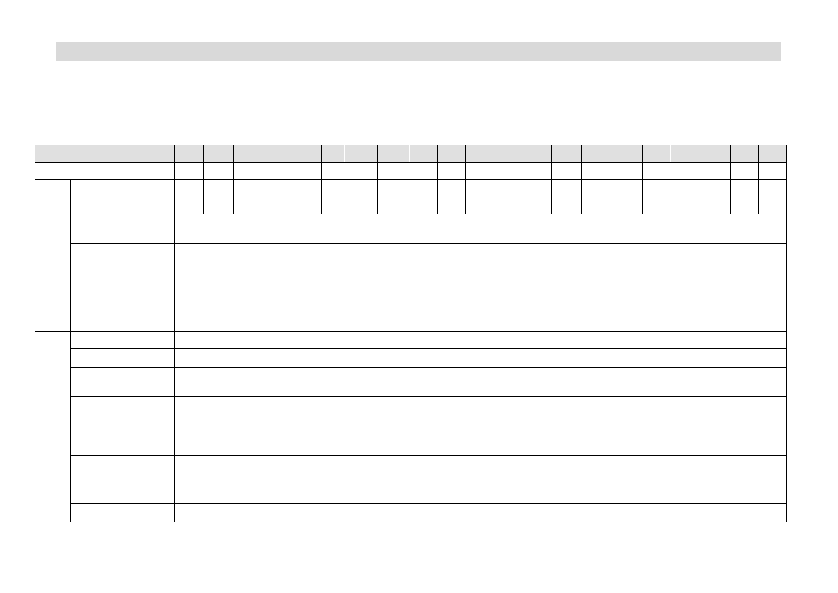
Standard specifications and performance parameters
Please see Table 1-4 for standard specifications and performance parameters of 3-phase Class 400V driver
Table 1-4 Standard specifications and performance parameters of GH DRIVER
Page 16
CTB GH DRIVER
Overload capacity
200% rated current 30s
Input and output interface
Digital quantity input
7-channel isolation photo-coupler input; input mode: PNP, NPN optional
Digital quantity
output
2-channel isolation photo-coupler output; 24V, 10mA
Analog input
2-channel; -10V~+10V 1 channel, 0~10V 1-channel
Analog output
2-channel; -10V~+10V
Relay output
1 channel: a group of N.O/N.C contact: AC250V/DC30V, 1A
Fault output relay
1 channel: a group of N.O/N.C contact: AC250V/DC30V, 1A
Encoder input
interface
two: maximum receive frequency is 300KHz: cable driven receive mode: RS422 standard
PULSE input
interface
One: direction PULSE or orthotropic PULSE
Encoder output
interface
One: maximum output frequency is 300KHz: cable driven output mode: RS422 standard
Bus interface
None
function
Speed control
Range: 0~15000rpm; turning: positive and negative; speed order: Analog, PULSE frequency
Accurate stop
Accuracy: ±1PULSE; position adjustment: set by user's parameter
Rigid tapping
May be connected to several domestic and foreign systems. Tapping error: ±2%
Other function
C-axis control, thread cutting, electronic gear, reaming, swing control
Protection
function
motor over-current
Greater than 200% rated current output
Motor overload
Specified time of exceeding overload alarm value. Alarm output: set by parameters
Overvoltage
The voltage of main circuit bus is higher than 800V. Alarm output
Low voltage
The voltage of main circuit bus is lower than 400V. Alarm output
Service
environment
Service site
Free of dust, corrosive gas and inflammable gas
Temperature
-10~45℃
Humidity
Lower than 95%RH (no condensation)
Vibration
vibration frequency≤20Hz: 9.8m/s2;20Hz≤vibration frequency≤50Hz: 2m/s
2
;
Page 17
GS DRIVER CTB
Dimension
Model
A B W H D
Connecting
terminal screw
Installati
on screw
Weight (kg)
BKSC-41P5GHX
45.
5
276
91
290
200
Wire nail width
3mm
M6
3
BKSC-42P2GHX
BKSC-43P7GHX
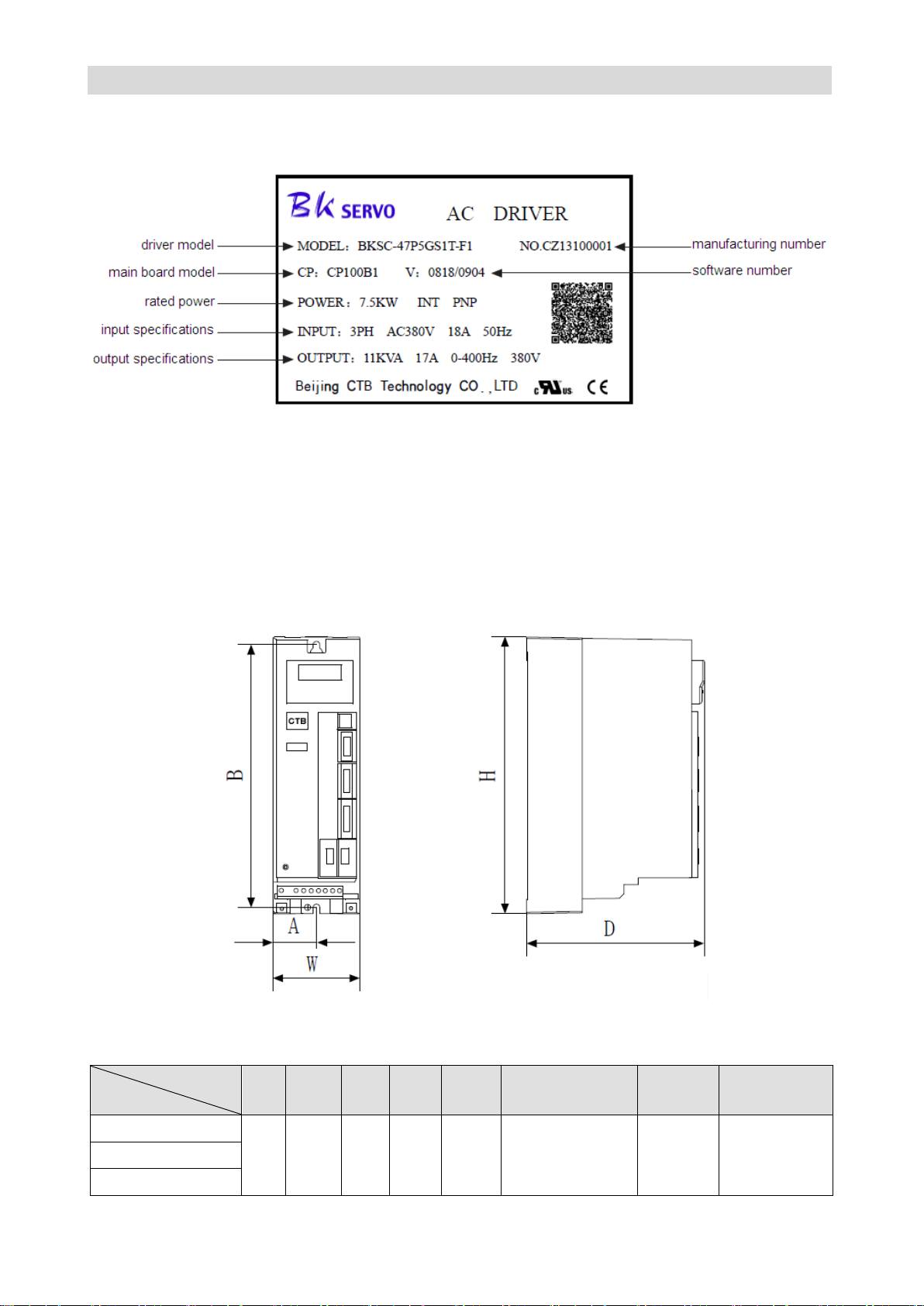
Driver nameplate description
Nameplate which indicates model and rated values of the driver is affixed to the lower right of housing of
the driver. The content of the nameplate is shown in Figure 1-1.
Figure 1-1 AC Servo driver nameplate
Note: the two-dimension code includes manufacturing number of the driver; customer name of the driver
(take BEIJING CTB SERVO CO., LTD. as an example); contract number; driver model; main board
model; software number; non-standard (take standard as an example) and other description.
External dimensions and installation dimensions
1. 1.5-3.7kw driver
Please see diagram 1-2 for external dimensions and installation dimensions
Figure 1-2
Table 1-5 Dimensions (mm) and weight (kg) of GH DRIVER (1.5-3.7kw) driver
Page 18
CTB GH DRIVER
Dimension
Model
A B W H D
Connecting
terminal screw
Installation
screw
Weight
(kg)
BKSC-45P5GHX
80
276
132
290
200
Wire nail width
3mm
M6
5
BKSC-47P5GHX
BKSC-4011GHX
Dimension
Model
A B W H D
Connecting
terminal screw
Installation
screw
Weight
(kg)
BKSC-4015GHX
140
376
194
390
228
M6
M6
14
BKSC-4018GHX
BKSC-4022GHX
236
376
282
390
228
M6
M8
20
BKSC-4030GHX
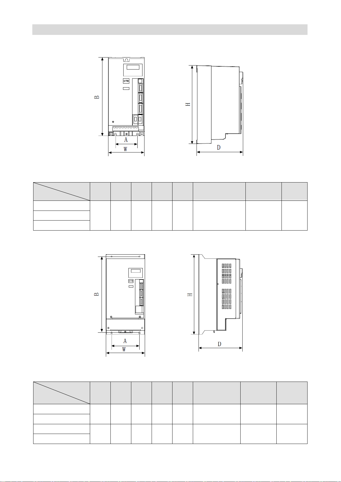
2. 5.5~11kw driver
Please see diagram 1-3 for external dimensions and installation dimensions
Figure 1-3
Table 1-6 Dimensions (mm) and weight (kg) of GH DRIVER (5.5-11kw) driver
3. 15~45kw driver
Please see diagram 1-4 for external dimensions and installation dimensions.
Figure 1-4
Table 1-7 Dimensions (mm) and weight (kg) of GH DRIVER (15-45kw) driver
Page 19
GS DRIVER CTB
BKSC-4037GHX
300
376
380
390
269
M8
M8
26
BKSC-4045GHX
Dimension
Model
A B W H D
E
Connecting
terminal screw
Installati
on screw
Weight
(kg)
BKSC-4055GHX
392
376
472
390
269
196
M10
M8
33
BKSC-4075GHX
BKSC-4090GHX
360
690
464
720
320
180
M10
M16
90
BKSC-4110GHX
BKSC-4132GHX
BKSC-4160GHX
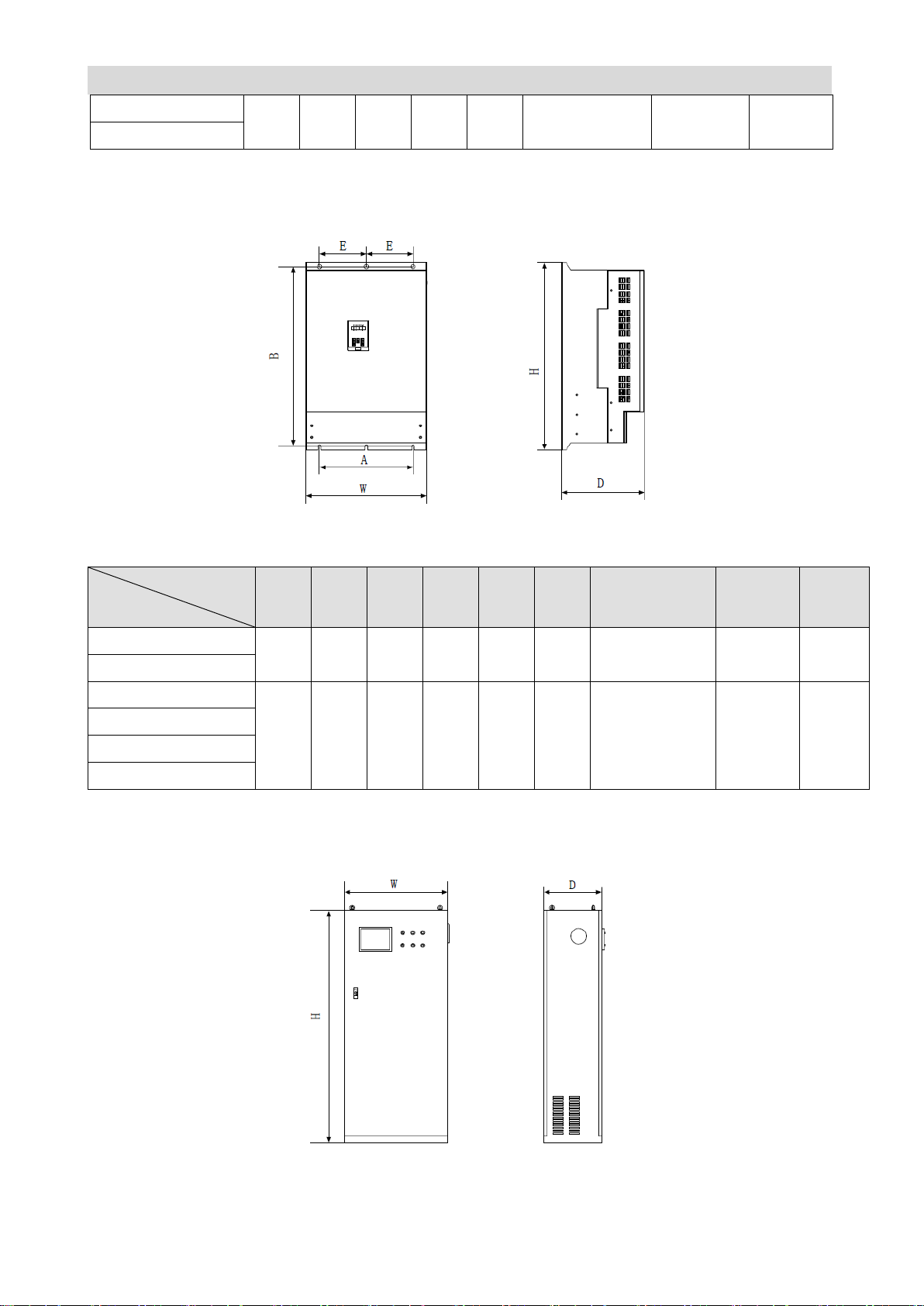
4. 55~160kw driver
Please see diagram 1-5 for external dimensions and installation dimensions
Figure 1-5
Table 1-8 Dimensions (mm) and weight (kg) of GH DRIVER (55-160kw) driver
5.200 ~ 315kw driver
Please see diagram 1-6 for external dimensions and installation dimensions
Figure 1-6
Table 1-9 Dimensions (mm) and weight (kg) of GH DRIVER (200-315kw) driver
Page 20
CTB GH DRIVER
Dimension
Model
A B W H D
Connecting
terminal screw
Installation
screw
Weight
(kg)
BKSC-4200GHX
- - 800
1800
450 - -
230
BKSC-4250GHX
BKSC-4315GHX
Confirmation and requirements of the installation space
Installation environment
The following items shall be noted when selecting the installation environment:
1. Ambient temperature: operate in -10℃ ~ 45℃; if the ambient temperature is higher than 45℃, the
equipment shall be used with 30% derating for each 5℃ temperature rise.
★ Note: If the ambient temperature is higher than 45℃, the ventilation shall be strengthened, and use by
the specified derating.
2. The humidity of the installation site shall lower than 95%, and free of condensing;
3. Do not install the equipment in place with dust or metal powder;
4. The equipment shall be installed at place without corrosive, explosive gas;
5. The equipment shall be installed at place that meets the requirements of vibration. The vibration
frequency ≤ 20Hz: 9.8m/s2; 20Hz ≤ vibration frequency ≤ 50Hz: 2m/s
6. The equipment shall be installed at place away from direct sunlight.
2
;
Installation direction and space
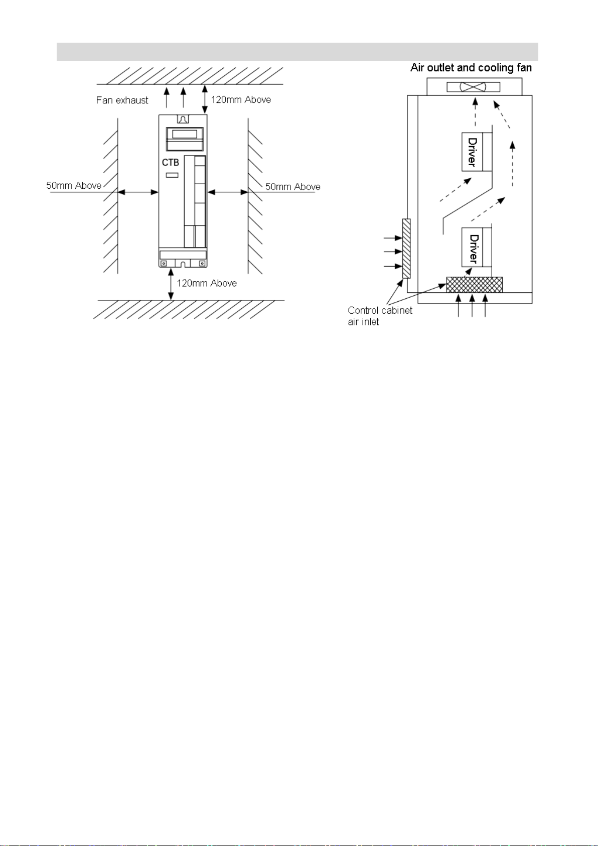
●Installation spacing and distance requirements of single driver are shown in Figure 1-7.
● Generally, abreast installation mode is adopted when multiple drivers are installed in the control
cabinet, and air inlet, outlet and dedicated cooling fan shall be equipped; if up and down installation
mode is adopted, stream guidance clapboard shall be added between drivers to guarantee good cooling
effect as shown in Figure 1-8.
Page 21
GS DRIVER CTB
Figure 1-7 Single controller installation
Figure 1-8 Multiple controllers installation
Notes on motor and load
Compared with frequency conversion operation
GH DRIVER is full closed-loop vector servo driver. It adjusts output voltage and current automatically
according to the load change. It's more energy-efficient than inverter with higher speed control accuracy
and wider speed regulation range. As the controlled motor and driver are closed loop, the control of
position, speed and torque can be achieved conveniently.
Constant torque operation
When motor works in constant torque area, the output torque of the motor is required by the mechanical
operation instead of the rated torque of the motor. However, the maximum continuous output torque of
the motor must not exceed the rated torque.
High-speed operation in constant power area
For high-speed operation in constant power area, the increased vibration and noise shall be considered,
and the service speed range of motor bearing and mechanical devices must be confirmed, and
consulted in advance. It's strictly prohibited to make the machine operate above the rated speed.
Lubrication of the mechanical device
For reduction box and gear head motor and other mechanical device that requires lubrication, damage
may be caused due to deterioration of lubricating effect in long-term low-speed operation. It must be
consulted in advance.
Negative torque load
Negative torque load occurs frequently for load such as lifting. The driver will generate over-current and
overvoltage alarm and trip. Equipping of brake components or mechanical safety devices shall be
considered.
Page 22
CTB GH DRIVER
Reciprocating load
Please pay attention to unstable phenomenon in output current when the driver is driving piston
reciprocating load. The phenomenon is more prominent in long-term low-frequency operation. The
capacity of driver shall be increased.
Mechanical resonance point of the load device
The driver may encounter the mechanical resonance point of the load device in certain output frequency
range. It can be avoided by setting jump frequency.
Notes on the driver
Applications not in rated voltage
The servo driver shall not be used in voltage that not in the working voltage range. Please conduct
voltage transformation with appropriate step-up or step-down unit as required.
Note on the drive 3 phase input into 2-phase input
The device shall not be changed into 2-phase input, otherwise, default phase protection will occur.
Capacitor or pressure-sensitive device to improve power factor
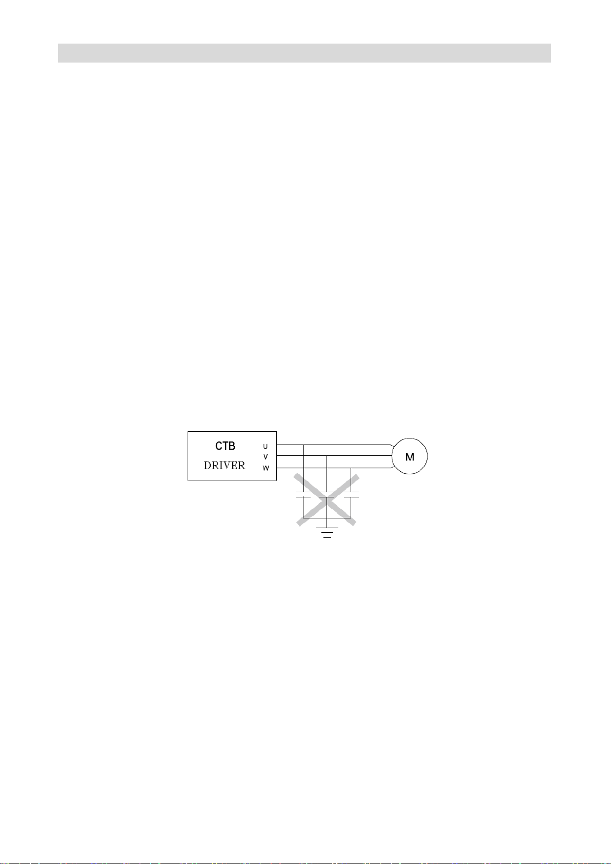
As shown in Figure 1-9, the output of the driver is PULSE wave, drive failure tripping or damage to the
device will be caused due to capacitor or pressure-sensitive device for lightning to improve power factor
installed at the output side. They must be removed.
Figure 1-9 Capacitor is prohibited at the output end of controller
Lightning attack protection
lightning over-current device is equipped in the driver for self-protection to induction stroke
Altitude and derating operation
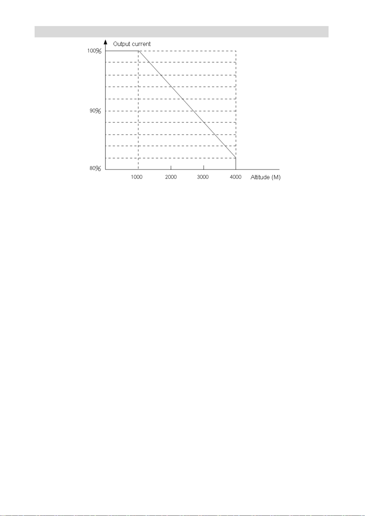
For areas with altitude over 1000 m, derating operation is necessary due to deterioration of cooling effect
of the drive caused by thin air. The relationship curve of rated current of driver and altitude is shown in
Figure 1-10.
Page 23
GS DRIVER CTB
Figure 1-10 Derating curve of rated current of driver and altitude
Notes on scrapping:
Explosion of electrolytic capacitor: the electrolytic capacitors on main circuit and printed panel may
explode when incinerated.
Plastic incineration waste gas: toxic gases will be generated in incineration of front panel and other
plastic parts.
Processing method: please process the waste as industrial waste.
★ Description: The contents of the manual are subject to change due to product upgrade or optimize.
The new version shall prevail.
Page 24
CTB GH DRIVER
Wiring
The chapter describes the wiring specifications of power supply terminals and control circuit
terminals, and install wiring specifications of control board jumpers and expansion interface
board.
Selection and connection of peripheral devices…………………………………..…………..2-2
Wiring of the main circuit terminals…..……………………………………………..…………2-3
Wiring of control circuit ……………………….………………………………………………..2-11
Connection of the encoder interface………….……………………..………………………..2-20
Connection of the serial communication port …….……………………………………..…..2-21
Page 25
GS DRIVER CTB
Item
Usage
Selection note
Remarks
Air circuit breaker
Turn on or off driver power
Select by 150% of rated
current of the driver
Refer to Table 2 - 3
Electromagnetic
contactor
For automatic power on of
driver
Select by 150% of rated
current of the driver
Refer to Table 2 - 3
Input side reactor
Improve power factor of
power grid
Select by 100% of rated
current of the driver
Input noise filter
Suppress interference of
driver to power supply
Select by 150% of rated
current of the driver
Braking resistor
Consume regenerated
energy of the driver
Select by standard provided
by the factory
Refer to Table 2 - 2
Filtering magnet
ring
Suppress wireless
interference of the driver to
outside
Select by standard provided
by the factory
Refer to GH model
selection sample
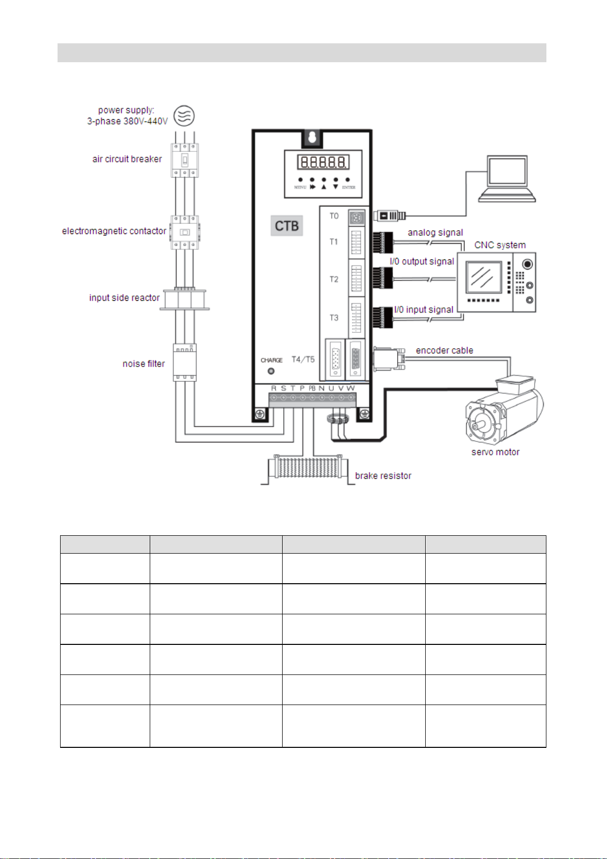
Selection and connection of peripheral devices
Driver and peripheral devices connection diagram taking 7.5kw drives as an example in Figure 2-1.
Figure 2-1 driver and peripheral devices connection diagram
Parts selection description
Page 26
CTB GH DRIVER
Wiring of the main circuit terminals
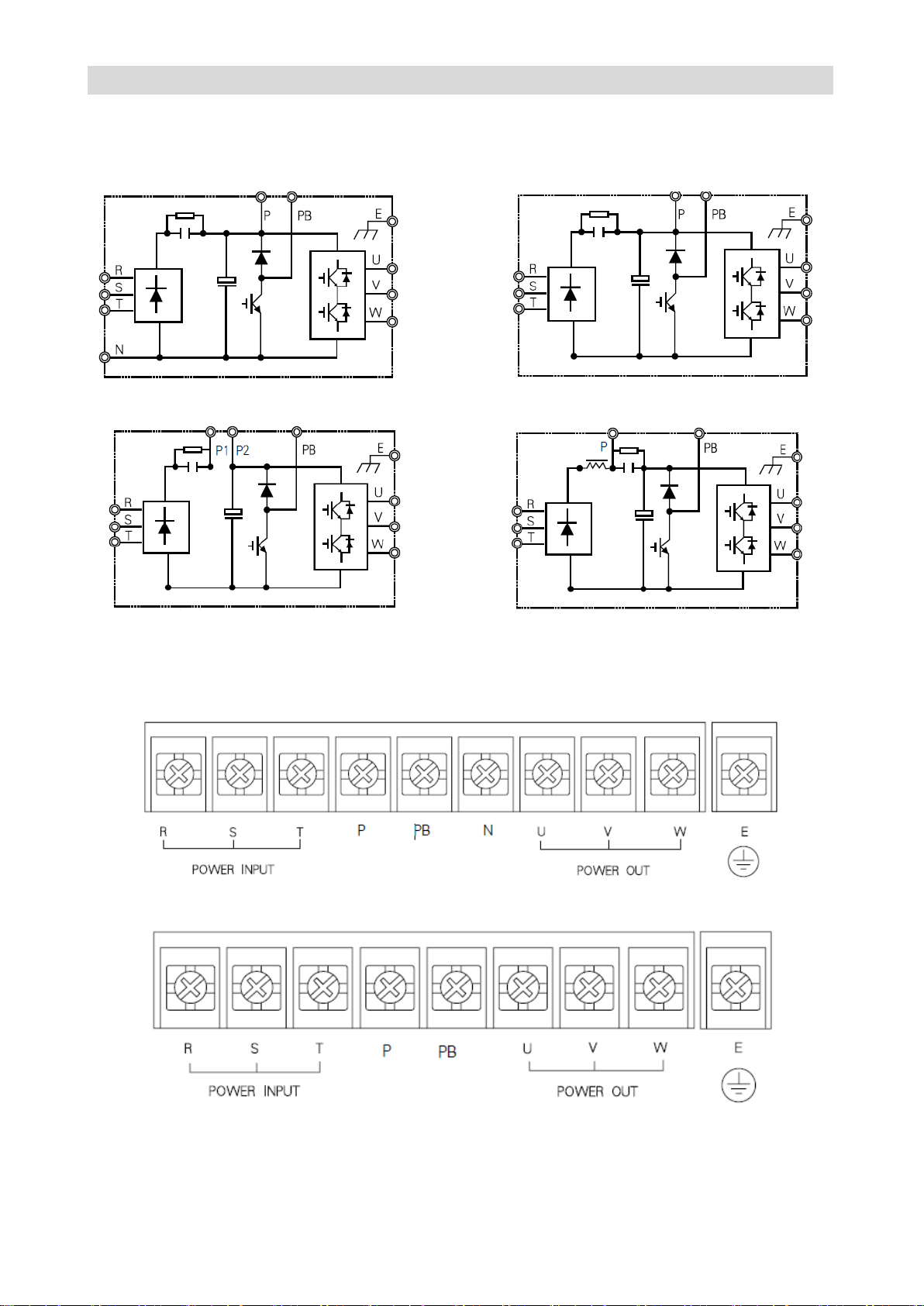
The structure of the main circuit
See Figure 2-2A, 2-2B, 2-2C and 2-2D for internal structure diagram of the main circuit.
Figure 2-2A 1.5~11kw main circuit composition Figure 2-2B 15~30kw main circuit composition
Figure 2-2C 37~75kw main circuit composition Figure 2-2D 90~160kw main circuit composition
Main circuit terminals composition
1.5~11kw main circuit terminals composition
1.5~30kw main circuit terminals composition
Page 27
GS DRIVER CTB
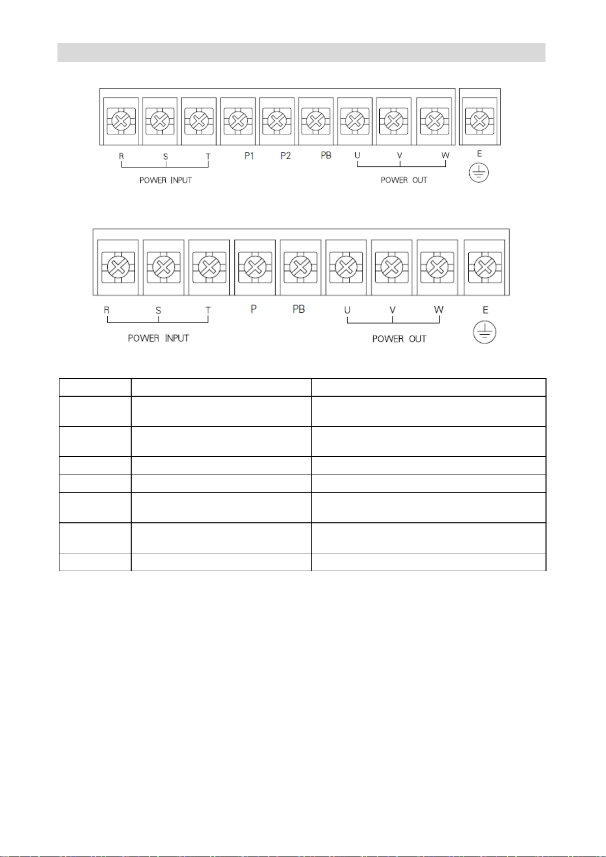
Item
Function
Notes
R S T
3-phase AC supply input terminal.
380~440V, 50/60Hz
Need to install breaker for protection
P P1
DC bus positive pole
P and N are for input of external braking unit or
DC power input
P2
DC reactor wiring terminal
P1 and P2 are for external DC reactor
PB
Braking resistor wiring terminal
P, P2 and PB are for external braking resistor
N
DC bus negative pole
N and P are for external braking unit or DC
power input
U V W
Driver output terminal
Consistent with the phase sequence of the motor
during wiring
E
Earth terminal
C type grounding, the grounding resistance≤ 4Ω
37~75kw main circuit terminals composition
90~160kw main circuit terminals composition
Main circuit terminals and functional description
Wiring of input side of the main circuit
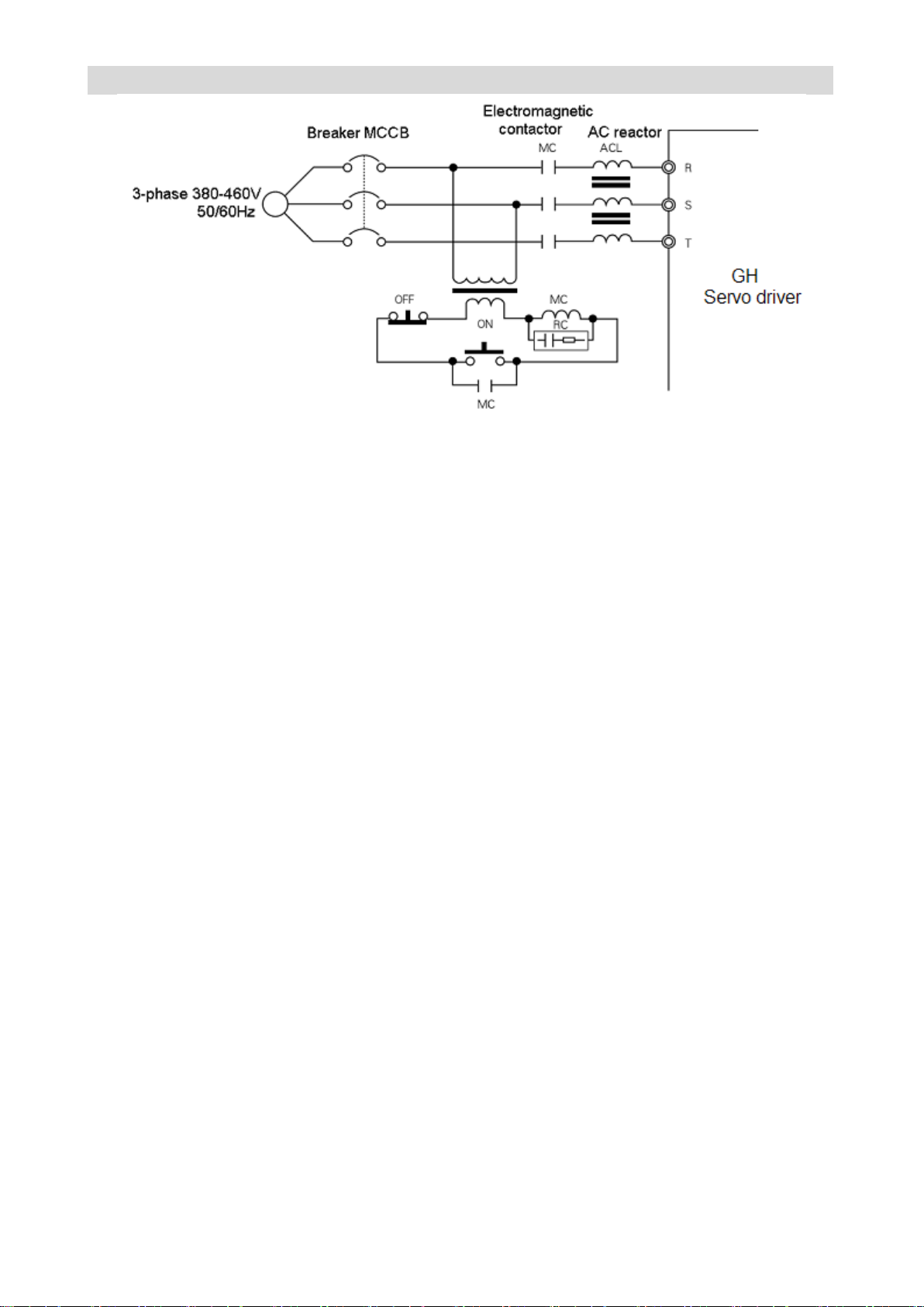
Please pay attention to the following items for wiring of input side of the main circuit. See2-3
Page 28
CTB GH DRIVER
Figure 2-3 Standard wiring diagram for incoming line
Incoming line circuit breaker (MCCB)
The main circuit power input terminals (R, S, T) must be connected to 3-phase AC power through line
protection circuit breaker (MCCB).
● The selection of MCCB must be in accordance with requirements in Table 2-3.
● The time characteristics of MCCB must take overload characteristics (rated output current 200%/min)
and time characteristics of the servo driver into account.
● Each AC servo driver shall be equipped with independent breaker; when multiple drivers share a
circuit breaker, to cut off the power supply and prevent the failure expansion during driver failure, it's
recommended to control the incoming line electromagnetic contactor with the fault output relay of the
driver to ensure safety.
Installation of the residual current circuit breaker
The output of the servo driver is a high frequency PULSE wave so that there is high-frequency leakage
current generated. Residual current circuit breaker can be used at the incoming line side of the driver to
remove high-frequency leakage current, and only inspect channel current that dangerous to human body.
Please select special residual current circuit breaker for servo (inverter) for wiring.
● When select special residual current circuit breaker, please select model for control of one driver with
an induction current over 30ma.
●When select normal residual current circuit breaker, please select model for control of one driver with
an induction current over 200ma, and a time over 0.1s.
●Installing isolation transformer between normal residual current circuit breaker and AC servo driver can
effectively avoid malfunction of the breaker.
Incoming line electromagnetic contactor
Incoming line electromagnetic contactor may be used to cut off the power in sequential control. It cannot
be used as start of AC servo driver. When cut off power of AC servo driver compulsorily with incoming
line electromagnetic contactor, AC servo driver is in power-off alarm state, motor only can slide freely
and stop.
● Frequent turning on/off incoming line magnetic contactor may cause heating, even burning of charging
Page 29
GS DRIVER CTB
Driver model
41P5
42P2
43P7
45P5
47P5
4011
4015
4030
4037
4045
4055
4075
4090
4110
4132
4160
AC
reactor
Current
(A)
5 7 10
15
20
30
40
50
60
80
90
120
150
200
230
250
290
330
Model
ACL
0005
0007
0010
0015
0020
0030
0040
0080
0090
0120
0150
0200
0230
0250
0290
0490
DC
reactor
Current
(A)
Without connection to DC reactor
90
110
150
180
Built-in driver
Model
DCL
090
0110
0150
0180
resistor of the driver (driver interior).
● The time interval of turning on/off incoming line magnetic contactor shall be longer than 10 minutes.
AC reactor
Installing AC reactor at the incoming line side of the servo driver can effectively suppress the surge of
power, avoid burning of rectification part of the driver, and also can improve the power factor of the
power supply side. Please see Figure 2-3 for connection of AC reactor, see Table 2-1 for selection of AC
reactor.
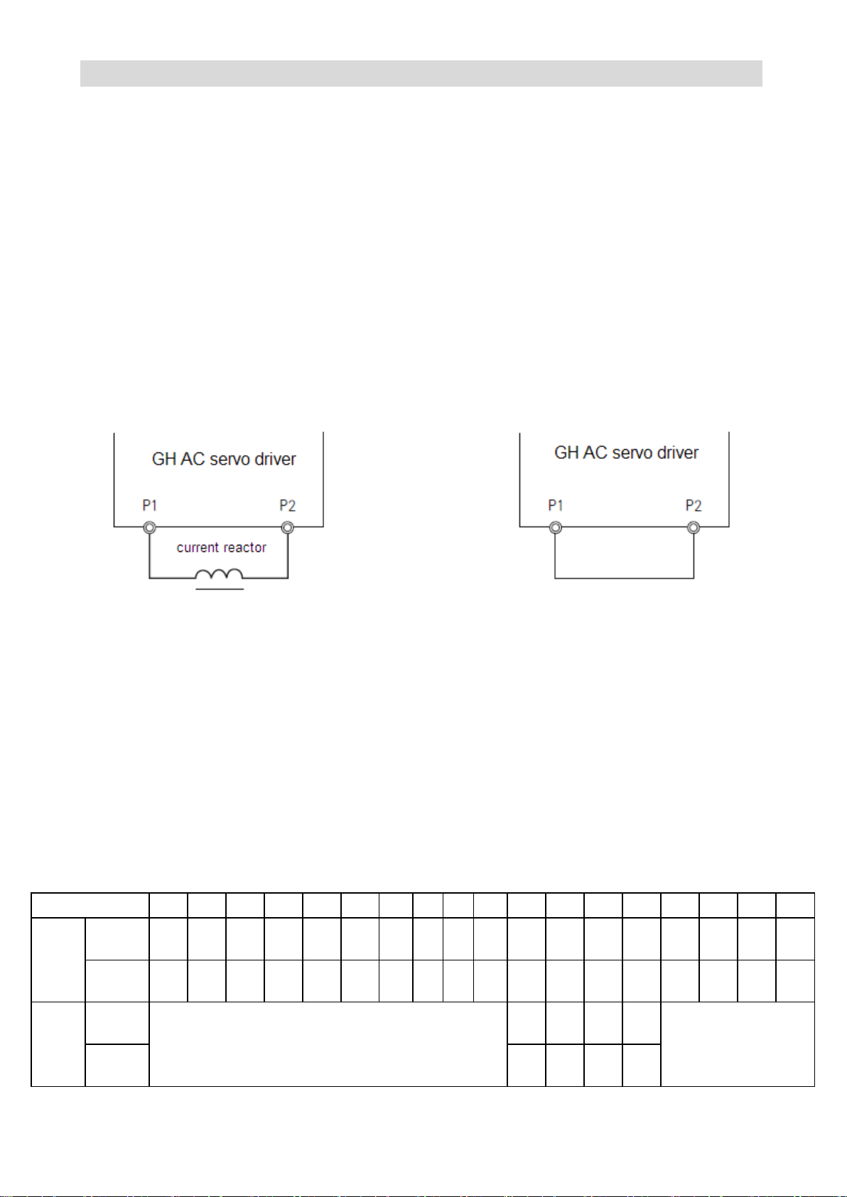
DC reactor
External DC reactor can be connected to GH AC servo driver of 37 to 75KW. It can effectively suppress
the surge of power, avoid burning of rectification part of the driver, and also can improve the power factor
of the power supply side. Please see Figure 2-4 for connection of DC reactor.
If external DC reactor is not connected, P1, P2 or D C + terminals shall be shorted as shown in Figure
2-5.
Figure 2-4 DC reactor connection diagram Figure 2-5 Connection diagram without DC reactor
Precautions for wiring of DC reactor
1. Please do not connect DC reactor to any main circuit terminal except P1, P2, otherwise, it may cause
internal short circuit of the driver, and burn the driver.
2. Please see Table 2-3 for specifications of DC driver connecting cable, the standard of the main circuit
cable.
3. Please see Table 2-1 for selection standard of DC reactor.
4. With external DC reactor, the P2 terminal shall be multiplex terminal, and one end of braking resistor
also shall be connected to the terminal.
Table 2-1 Selection of AC reactor, DC reactor and input filter
Page 30
CTB GH DRIVER
Input
filter
Current
(A)
6 6 6
10
16
25
30
50
50
65
80
100
120
150
200
250
250
320
Model
EMI
06
06
06
010
016
025
030
050
050
065
080
0100
0120
0150
0200
0250
0250
0320
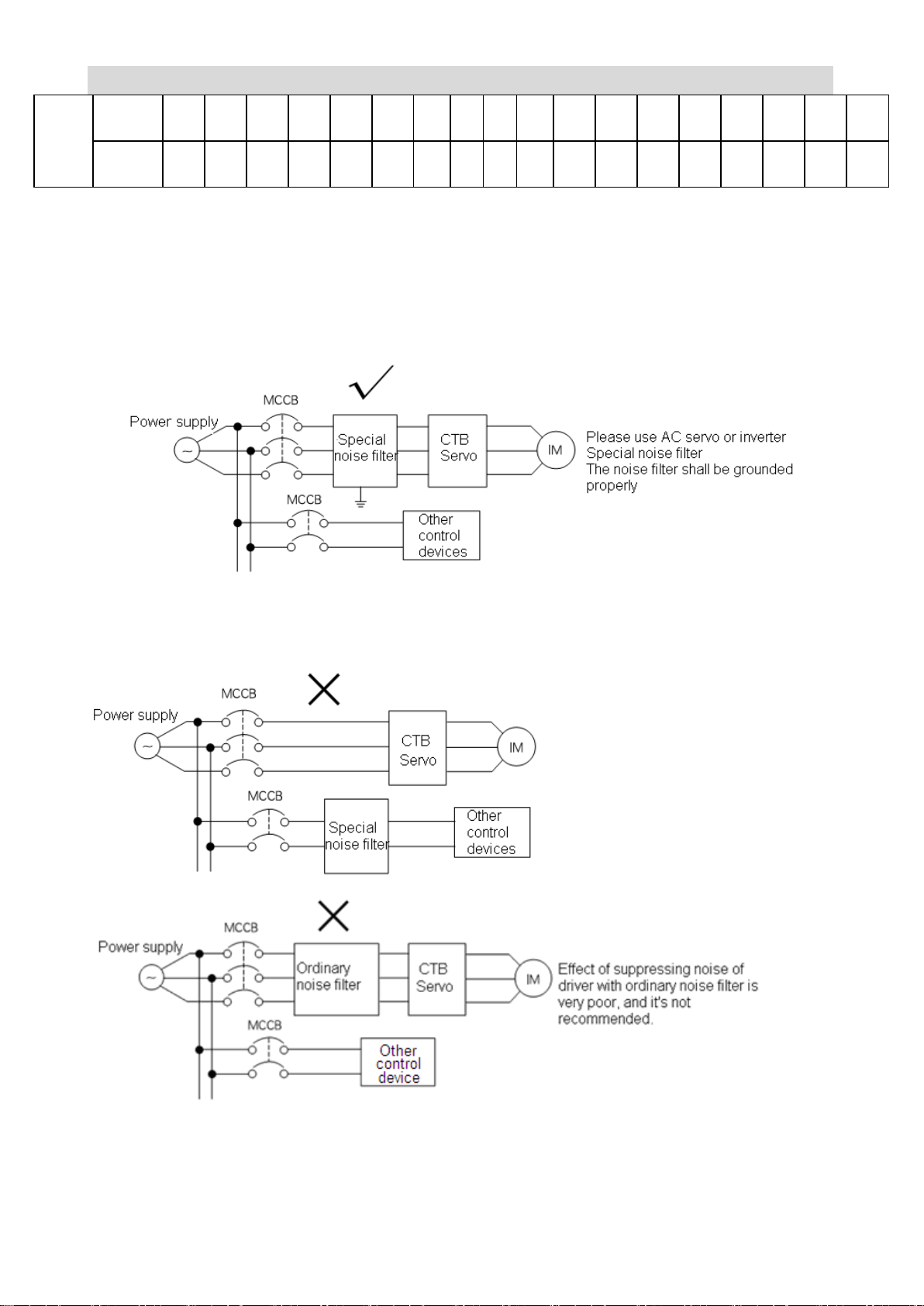
Power side noise filter
In command to reduce high-frequency interference noise from power line coupling to the driver, and
suppress the noise feedback to power from the driver, noise filter with appropriate model and
specifications at the power input side of the driver.
Set and connect the incoming line filter correctly as shown in Figure 2-6.
Figure 2-6 Correct installation of noise filter at the input side of the power supply
Please see Figure 2-7 for examples of incorrect settings and connection
Figure 2-7 Incorrect settings and connection of noise filter at the input side of the power supply
Page 31
GS DRIVER CTB
The AC servo driver and motor must be well grounded, otherwise it may make
the driver not functioning properly, even burn the driver.
Forbid
● It's strictly prohibited to connect the input power cord to the output terminal.
Never connect the input power cord to the output terminal, otherwise, it will lead to damage to internal
components of the controller.
● It's strictly prohibited to connect make the output terminal shorted and grounded.
Never touch the output terminal directly, or make the output line touch the controller housing for risk of
electric shock. In addition, never short the output line.
● It's strictly prohibited to use phase shift electrolytic capacitor, LC / RC noise filter.
Never connect phase shift electrolytic capacitor, LC / RC noise filter in output circuit. Damage to
internal components of the controller may be caused when use these components.
● It's strictly prohibited to connect or disconnect load with electromagnetic switch.
Never connect electromagnetic switch, electromagnetic contactor to connect or disconnect the load in
output circuit. During load operation, the protection circuit action of the controller will be acurated by
the surge current.
surge current will arose
● It's strictly prohibited to connect fan of motor to U / V / W output terminals of the driver.
It may burn the fan, and short-circuit the driver.
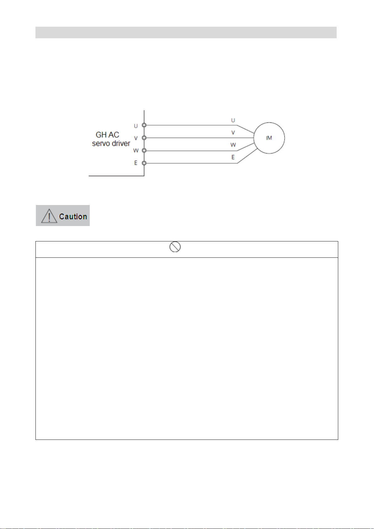
The wiring of output side of main circuit
The output terminals of U, V, and W of the driver shall be connected to the connecting terminals of U, V,
and W of three-phase AC motor by correct phase sequence; if the phase sequence is connected
wrongly, the driver will raise the wrong phase sequence alarm with an alarm number of E.PV. To solve
the problem, exchange phase sequence of any two phases. Please see Figure 2-8 for standard wiring of
the output side.
Figure 2-8 Output side wiring
Wiring distance between the driver and motor
Generally, the wiring distance between the AC servo driver and motor shall be shorter than 50 m. For
longer distance, please contact the manufacturer to select wire with smaller resistivity.
Page 32
CTB GH DRIVER
Inductive interference countermeasures
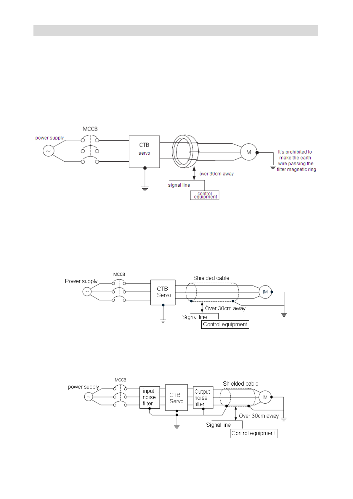
Three methods of suppressing radio interference and inductive interference are provided in the
information: filter magnetic ring, shielded cable and output filter.
Filter magnetic ring
Installing filter magnetic ring at the output side near to the driver can suppress common code
interference at the output side effectively, as shown in Figure 2-9.
Figure 2-9 Filtering magnetic ring installation diagram
Output shielded cable
Use shielded cable for output line of the AC servo driver can effectively suppress radio interference and
inductive interference. The ends of shielding layer of the shielded cable shall be grounded separately as
shown in Figure 2-10.
Figure 2-10 Connecting method of shielded cable
For applications of input and output filters in occasions with relatively large radio interference, output
filter can be used to suppress interference. The input side and the drive generate radio interference so
that the effect is best by using the input, output filter at the same time, as shown in Figure 2-11.
Figure 2-11 Suppress radio interference with output filter
Page 33
GS DRIVER CTB
BKSC-XXXX GHX
41P5 42
P2 43P7 45P5 47P5 4011 4015 4018 4022 4030 4037 4045 4055 4075 4090 4110 4132 4160 4200
4250
4315
Braking
resistor
ripple
Power
W
-
-
600 800 10
00 600 800 1000 1000 1500 2000 2000 2500 2500 2500 2500 2000 2000 2500
2500
2500
Resist
ance
Ω
- - 50
40
32
50
40
32
32
32
20
20
20
20
20
20
20
20
20
20
20
Qty.
- - 1 1 1 2 2 2 2 2 2 2 2 3 3 3 4 4 6 6 8
aluminu
m
housing
Power
W
200
300 600 800 10
00 600 800 1000 1000
Same parameters for ripple resistor
Resist
ance
Ω
150
10
0
50
40
32
50
40
32
32
Qty.
1 1 1 1 1 2 2 2 2
Filtering
magnet
ring
inside diameter
φ(mm)
15
15
15
18
18
23
23
23
27
27
38
38
38
38
38
44
44
44 ― ―
―
Thickness
H(mm)
13
13
13
13
13
15
15
15
15
15
24
24
24
24
24
15
15
15 ― ―
―
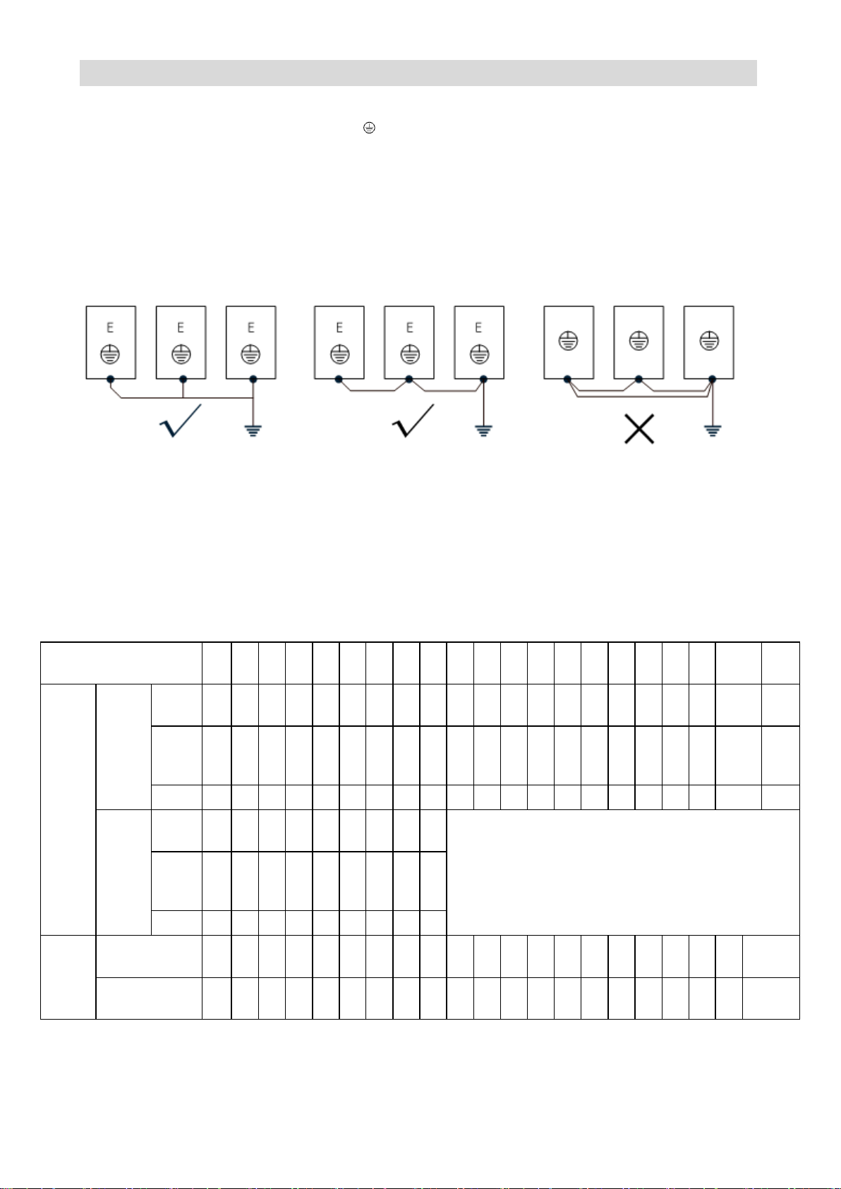
Connection of the grounding wire
● The ground terminal is identified as E or , please do ground.
● Earth resistance: below 4Ω.
● Do not share grounding wire with welder and other power equipment.
● Please select wire diameter specification for grounding wire as specification in technical standards of
electrical equipment, and as short as possible.
● Please make grounding wire forming a loop where more than two drivers are used.
● Example: as shown in Figure 2-12
Figure 2-12 Connection of grounding wire
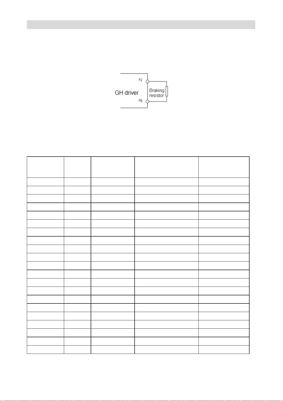
Connection of braking resistor
The P, PB terminals on main circuit block of AC servo driver are for connection with braking resistor.
Please do not connect braking resistor to other terminals, otherwise, the braking resistor will heat up and
burn out, or cause damage to the driver. Please see Table 2-2 for braking resistor selection.
Table 2-2 Specification of braking resistor
Note: above accessories data is standard data recommended by the manufacturer. For special
applications, please contact your supplier.
● The connection of braking resistor shall be in strict accordance with Figure 2-13.
Page 34
CTB GH DRIVER
Figure 2-13 Connection of braking resistor
Model
BKSC
Power
(kW)
Breaker
(air switch) (A)
Main circuit cable (copper
conductor cable) (mm2)
Contactor
Voltage: 380V.
Current:(A)
41P5GHX
1.5
10
2.5
9
42P2GHX
2.2
10
2.5
9
43P7GHX
3.7
16 4 16
45P5GHX
5.5
32 4 18
47P5GHX
7.5
40 6 25
4011GHX
11
63 6 32
4015GHX
15
63
10
50
4018GHX
18.5
100
16
63
4022GHX
22
100
16
80
4030GHX
30
125
25
95
4037GHX
37
160
35
115
4045GHX
45
200
35
115
4055GHX
55
200
50
150
4075GHX
75
225
70
185
4090GHX
90
250
70
250
4110GHX
110
400
95
250
4132GHX
132
400
120
315
4160GHX
160
400
150
400
4200GHX
200
630
185
400
4250GHX
250
630
240
500
4315GHX
315
800
300
630
● The length of connecting wire between driver and braking resistor shall be less than 50 m.
● Please pay particular attention to: external braking unit may be connected to p (+) / DC +, N (-) / DC
side of the driver, but direct connecting with braking resistor is not allowed, otherwise, damage to driver
or fire may be caused.
Selection of breaker, contactor and cable
Please see Table 2-3 for selection of breaker, contactor and input and output cable
Table 2-3 Specification of breaker, contactor and cable
Page 35
GS DRIVER CTB
Signal
Signal name
Cable
Cable(mm2)
specification
switching value
input /output
I1~I6 Q1~Q2 PV SC
common cable or
shielded cable
0.2~2
Relay output
M0A/M0B/M0C M1A/M1B/M1C
common cable or
shielded cable
0.2~2
Analog signal
FI FV FS FC FS FT
shielded cable
0.2~1
Encoder signal
PV1 G1 A+ A- B+ B- Z+ ZPV2 G2 OA+ OA- OB+ OB- OZ+ OZ-
Shielded twisted
twin cable
0.2~1
PULSE signal
SA+ SA- PB+ PB- DZ+ DZ-
Shielded twisted
twin cable
0.2~1
enable reset
signal
ST PV SC
common cable or
shielded cable
0.2~1
Control panel
model
switching
value
input
switching
value output
Analog
input
Analog
output
PULSE
input
Communication
interface
Encoder
input
Encoder
output
CP100A1/
CP100C1
7 4 2 2 ○
RS232
○
○
Main circuit wiring precautions
● Please do connect breaker or fuse between power supply and power input terminals (R, S, T) of the
driver.
● Please do connect to earth wire at E terminal of the driver. Copper core cable over 4mm
for earth wire with a grounding resistance lower than 4Ω.
● Please ensure the high reliability of wiring.
● Please check the following items after circuit wiring.
(1) Are all connections correct?
(2) Is there connection missing?
(3) Is there short circuit between terminals and connecting line or shorted to ground?
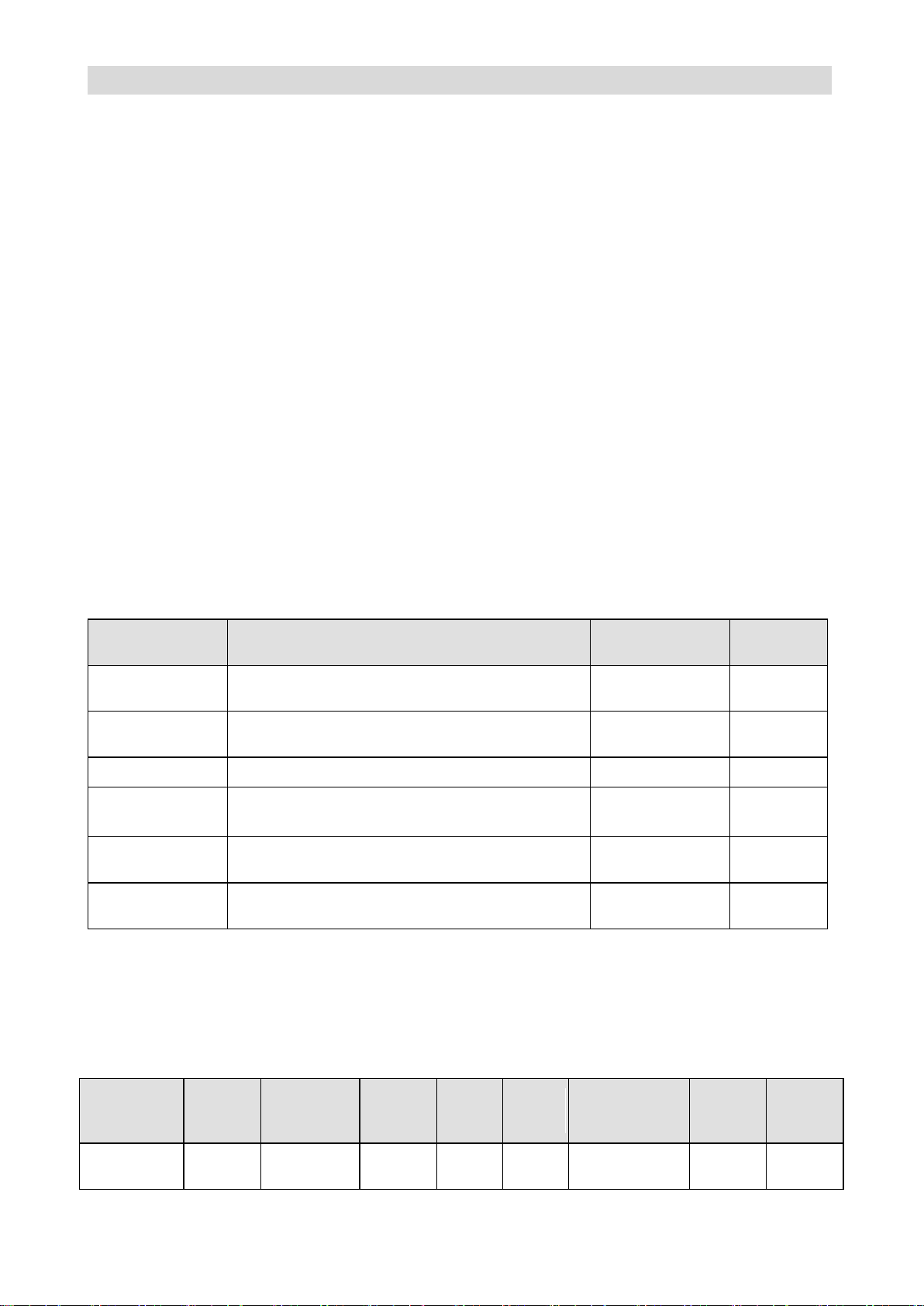
Control circuit wiring
Input and output signals of GH Series AC servo driver include: switching value input signal, switching
value output signal, Analog input signal, PULSE input signal, encoder input / output signal.
Specifications of input and output signal cable
2
shall be used
As the control signals are different, the requirements to cable for connector are strict. Specifications of
cable for different signal connectors are listed in Table 2-4. User shall follow the standard for wiring.
Table 2-4 Specifications of input and output signal cable
GH DRIVER control panel specifications
GH Series driver provides six kinds of control board according to different power and function of GH
Series driver. Please see Table 2-5 for interface characteristics and applicable model.
Table 2-5 GH DRIVER main board specifications
Page 36
CTB GH DRIVER
CP100B1/
CP100D1
14 8 2 2 ○
RS232
RS485
CAN
TCP/IP
○
○
CP100AT1/
CP100CT1
8 4 3 - ○
RS232
○
○
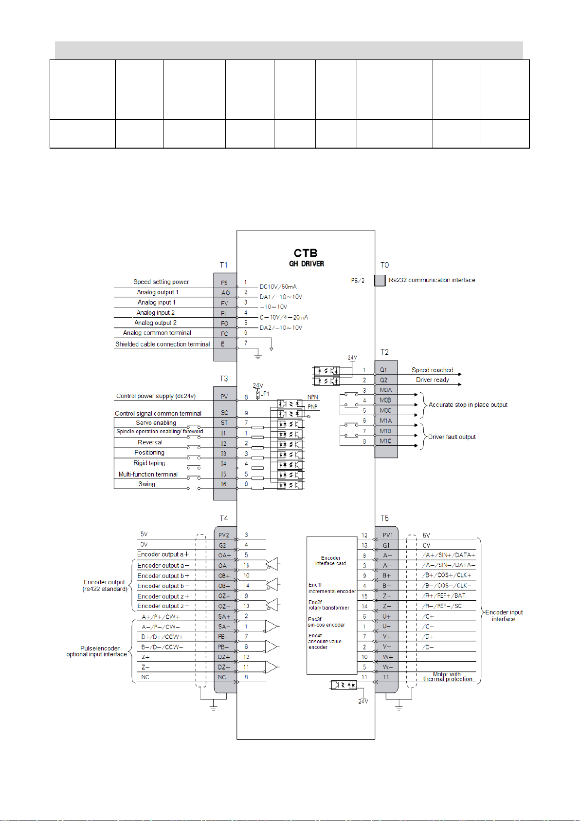
Standard version control wiring diagram (taking 7.5kW GH X driver as an
example)
Page 37
GS DRIVER CTB
Port
Type
Pin
Name
Function
Signal standard
T0
Communication
communicate with computer
RS232
T1
Analog input
1
FS
10V power for speed setting is
provided inside common port
DC10V 50mA
6
FC
analog input /output common
terminal
0V
3
FV
-10V~+10V analog input, input
impedance: 20KΩ
Analog signal
4
FI
Analog input impedance may be
selected for 0~10V , 4~20mA
impedance: 20K/500Ω
Analog output
2
AO
-10~10V output
5
FO
-10~10V output
T2
Programmable
optocoupler
output
1
Q1
speed reached
24V optocoupler
output 10mA
2
Q2
driver ready
Relay output
3/4/5
MOA/MOb/MO
c
output accurate stop end (in place)
output
Ac250V 1A
Dc30 1A
6/7/8
MIA/MIB/MIC
driver fault output
T3
Control signal
input
7
ST
control enabling and reset
PNP: 0V input
effective
NPN:24V input
effective
Input mode of
PNP or NPN
Shall be selected
by software
parameter setting
1
I1
Foreword/ operation enabling
2
I 2
reverse
3
I 3
accurate stop, close: start accurate
stop and maintain; open: cancel
accurate stop
4
I 4
rigid tapping signal, close : enter rigid
tapping state
5
I 5
multifunctional terminal
6
I 6
Swing
Control power
8
PV
DC24V power terminal, it’s 24V
output when JP1 is turned on, and
24V input when JP1 is shut down.
DC24V 100mA
9
SC
D 24V power 0V terminal /control
signal common port
T4
Encoder output
3/4
PV2/G2
Preset power, provided by digital
system, system without electrify
inspection may go without.
DC5V,200mA
5/15
OA + /OA-
encoder A phase output
line driver output
RS 422 standard
10/14
OB +/ OB-
encoder B phase output
9/13
OZ + /OZ-
encoder Z phase output
Encoder
2/1
SA + /SA-
encoder A phase/orthogonal PULSE
A phase input /single PULSE train
RS422 standard
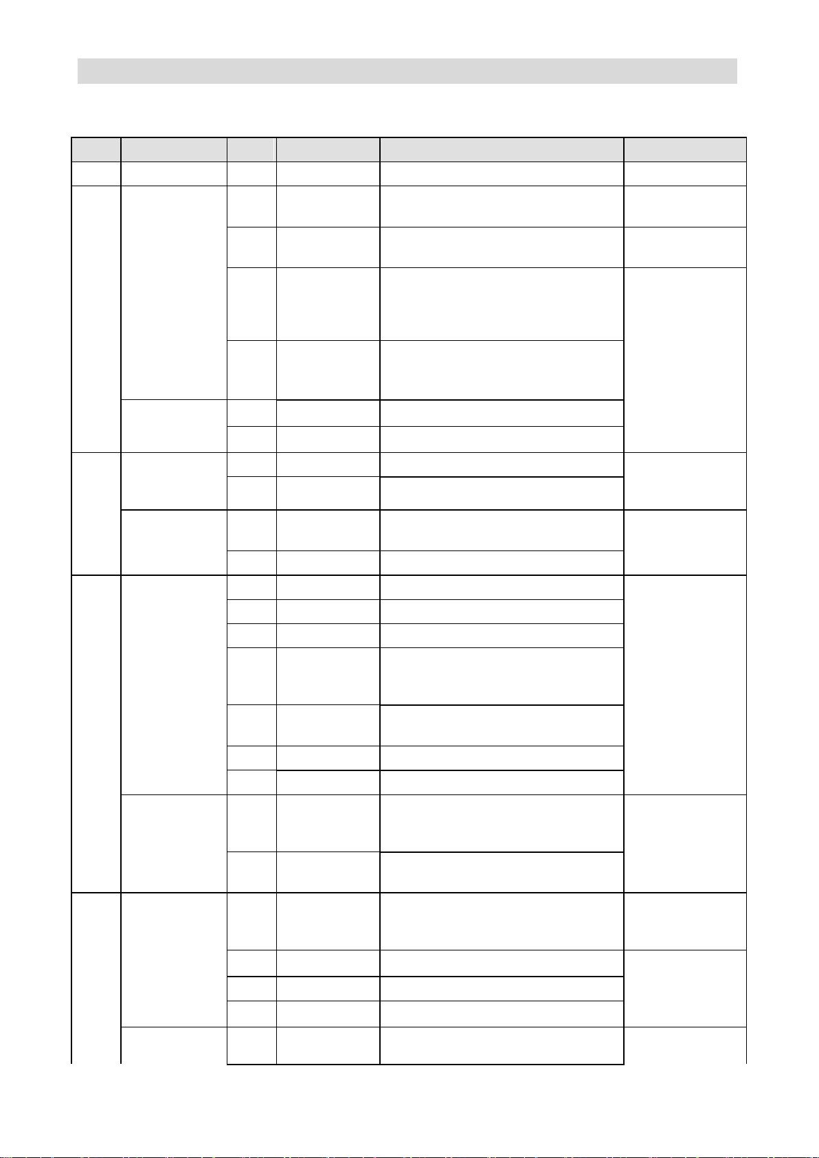
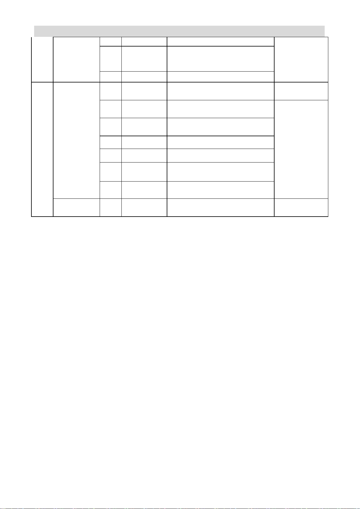
Input and output signals description (GHX Series)
Table 2-6 Input and output signal function description
Page 38
CTB GH DRIVER
PULSE input
input P
7/6
PB + /PB-
encoder B phase/orthogonal PULSE
B phase input /single PULSE
direction input D
12/11
DZ +/ DZ-
encoder Z phase
T5
Communication
encoder input
12/13
PV1/G1
encoder power supply provides
terminal /power common port
Dc5V 200mA
8/3
A +/ A-
A/A/SIN/DATA
INCRE/SIN-COS/Rotary/ABSOLUTE
Corresponding
encoder standard
9/4
B + /B-
B/B/COS/CLK
incre/SIN-COS/Rotary/ABSOLUTE
15/14
z +/ z-
Z/R/REF INCRE/SIN-COS/ROTARY
6/1
U+/U-
U/C increment/ sine and cosine
7/2
V+/V-
V/D increment/ sine and cosine
10/5
W+/W-
W increment
Thermal
protection input
11
T1
Motor thermal protection signal input
N.C./ N.O.
Page 39
GS DRIVER CTB
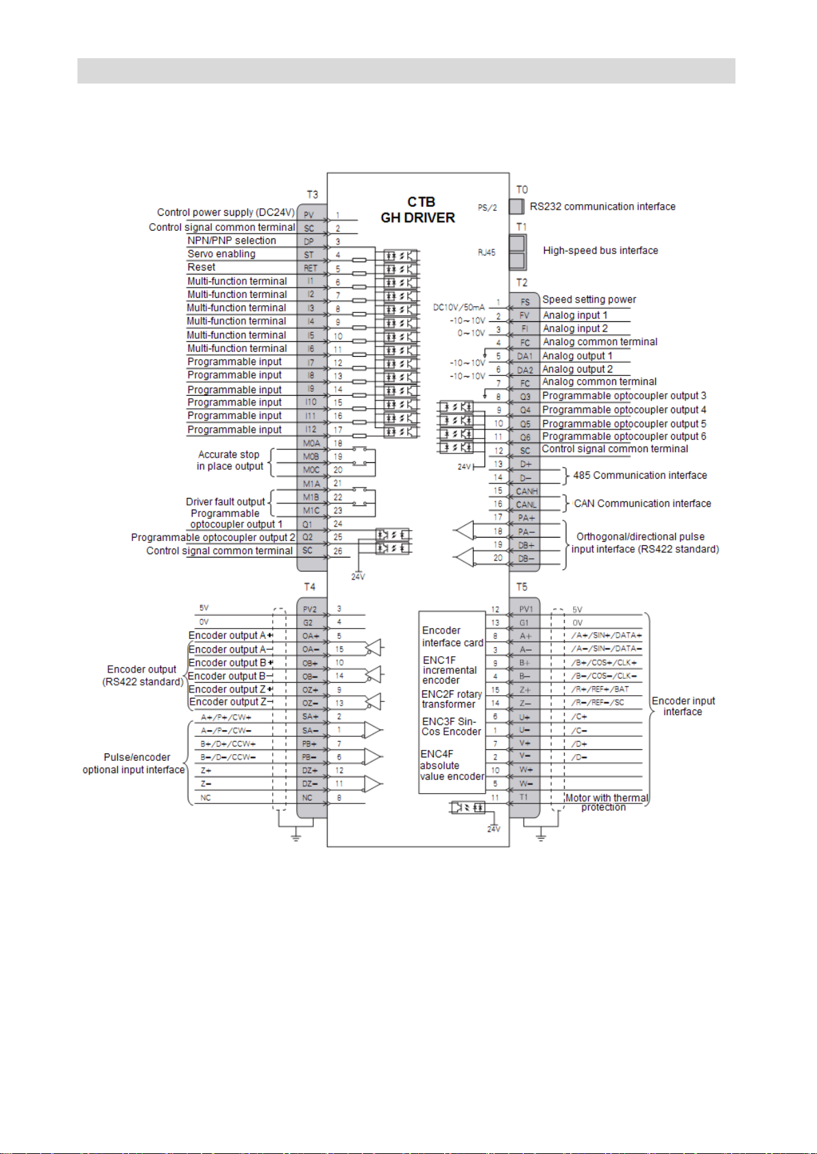
General version control wiring diagram (taking 7.5kW GHXB driver as an example)
Page 40
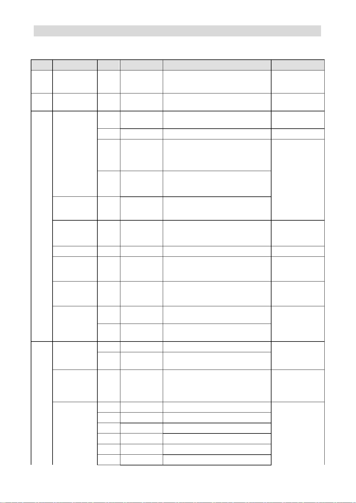
CTB GH DRIVER
Port
Type
Pin
Name
Function
Signal standard
T0
Communicatio
n
communicate with computer
RS232
T1
High-speed
bus interface
T2
Analog input
1
FS
10V power for speed setting is
provided inside common port
DC10V 50mA
4/7
FC
analog input /output common terminal
0V
2
FV
-10V~+10V analog input, input
impedance: 20KΩ
Analog signal
3
FI
Analog input impedance may be
selected for 0~10V , 4~20mA
impedance: 20K/500Ω
Analog output
5/6
DA1/DA2
-10~10V output
Programmable
optocoupler
output
8/9/10/
11
Q3/Q4/Q5/Q6
Programmable output
24V optocoupler
output 10mA
Control power
12
SC
Control signal common terminal
DC24V 100mA
485
communication
interface
13/14
D+/D-
485 communication interface
RS485 standard
CAN
communication
interface
15/16
CANH/CANL
CAN communication interface
CAN
communication
standard
orthogonal/dire
ctional pulse
input interface
17/18
PA+/PA-
orthogonal/directional pulse input
interface
RS422 standard
19/20
DB+/DB-
orthogonal/directional pulse input
interface
T3
Control power
supply
1
PV
DC24V power supply terminal
DC 4V 100mA
2
SC
DC24V power supply 0V terminal
/control signal public terminal
NPN/PNP
select
3
DP
NPN/PNP select
DP connections to
PV is NPN, and
DP connecting to
SC is PNP
Control signal
input
4
ST
Control enabling and reset
PNP: 0V input
effective
NPN:24V input
effective
5
RET
Reset
6
I1
Multi-function terminal
7
I 2
Multi-function terminal
8
I 3
Multi-function terminal
9
I 4
Multi-function terminal
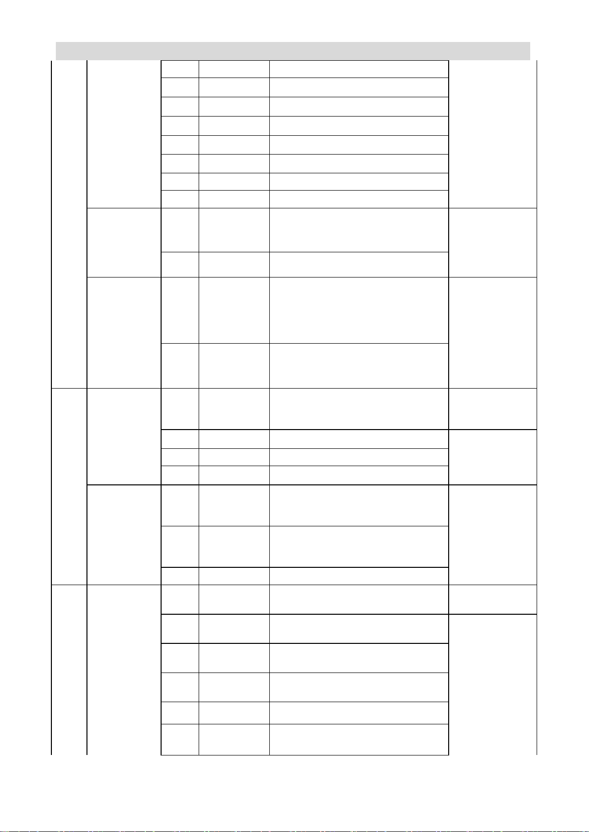
Input and output signals description (GHXB Series)
Table 2-7 Input and output signal function description
Page 41
GS DRIVER CTB
10
I 5
Multi-function terminal
11
I 6
Multi-function terminal
12
I 7
Programmable input
13
I 8
Programmable input
14
I 9
Programmable input
15
I 10
Programmable input
16
I 11
Programmable input
17
I 12
Programmable input
Programmable
optocoupler
output
24
Q1
Speed reached
24V optocoupler
output 10mA
25
Q2
Driver is ready
Relay output
18/19/
20
M0A/M0B/M0
C
Output accurate stop ends (in place)
output
AC 250V 1A
DC30 1A
21/22/
23
M1A/M1B/M1
C
Driver fault output
T4
Encoder output
3/4
PV2/G2
Preset power, provided by digital
system, system without electrify
inspection may go without.
DC5V,200mA
5/15
OA + /OA-
encoder A phase output
line driver output
RS 422 standard
10/14
OB +/ OB-
encoder B phase output
9/13
OZ + /OZ-
encoder Z phase output
Encoder
PULSE input
2/1
SA + /SA-
encoder A phase/orthogonal PULSE
A phase input /single PULSE train
input P
RS422 standard
7/6
PB + /PB-
encoder B phase/orthogonal PULSE
B phase input /single PULSE direction
input D
12/11
DZ +/ DZ-
encoder Z phase
T5
Communicatio
n encoder
input
12/13
PV1/G1
encoder power supply provides
terminal /power common port
Dc5V 200mA
8/3
A +/ A-
A/A/SIN/DATA increment /sine and
cosine / resolver / absolute value
Corresponding
encoder standard
9/4
B+ /B-
B /B/COS/CLK increment /sine and
cosine / resolver / absolute value
15/14
z +/ z-
Z /R/REF increment /sine and cosine /
resolver
6/1
U+/U-
U/C increment/ sine and cosine
7/2
V+/V-
V/D increment/ sine and cosine
Page 42
CTB GH DRIVER
10/5
W+/W-
W increment
Thermal
protection
input
11
T1
Motor thermal protection signal input
N.C./ N.O.
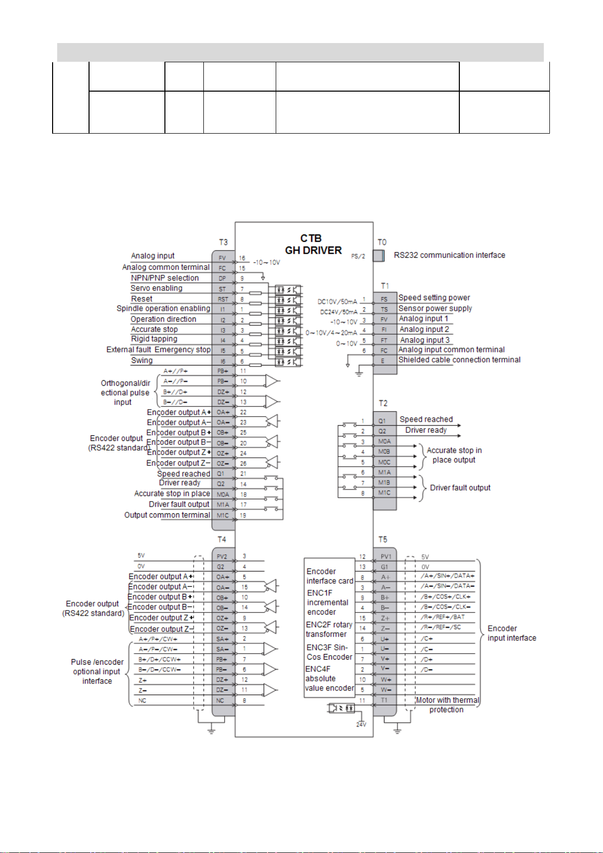
Special version control wiring diagram (taking 7.5kW GHXT driver as an
example)
Page 43
GS DRIVER CTB
Port
Type
Pin
Name
Function
Signal standard
T0
Communication
communicate with computer
RS232
T1
Analog input
1
FS
10V power for speed setting is
provided inside
DC10V 50mA
6
FC
analog input common terminal
0V
3
FV
-10V~+10V analog input, input
impedance: 20KΩ
Analog signal
4
FI
Analog input impedance may be
selected for 0~10V , 4~20mA
impedance: 20K/500Ω
2
AO
-10V~+10V analog quantity output
5
FO
-10V~+10V analog quantity output
T2
Relay output
1
Q1
Speed reached
AC 250V 1A
DC30 1A
2
Q2
Driver ready
3/4/5
M0A/M0B/M0
C
Output accurate stop ends (in place)
output
6/7/8
M1A/M1B/M1
C
Driver fault output
T3
Analog input
16
FV
-10~10V analog quantity input
Analog signal
15
FC
Analog input common terminal
NPN/PNP
selection
9
DP
NPN/PNP selection
DP is NPN when
connected to PV.
DP is PNP when
connected to SC.
7
ST
Control enabling and reset
PNP: 0V input
effective
NPN:24V input
effective
8
RET
Reset
1
I1
Forward/operation enabling
2
I2
Reversal
3
I 3
Accurate stop, close: start accurate
stop and hold; switch off: cancel the
accurate stop
4 I 4
Rigid tapping signal, close; enter
rigid tapping state
5 I 5
Multi-function terminal
6 I 6
Swing
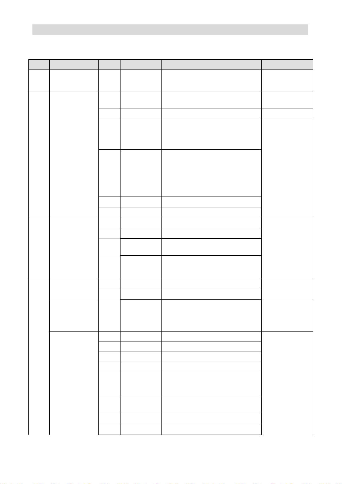
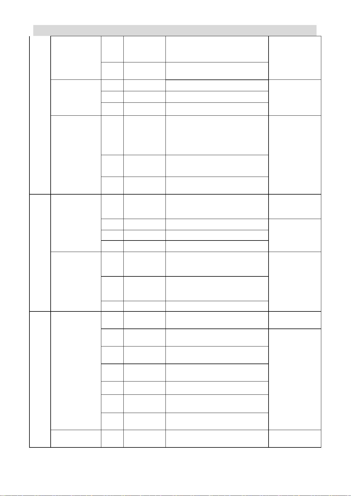
Input and output signals description (GHXT Series)
Table 2-8 Input and output signal function description
Page 44
CTB GH DRIVER
Orthogonal/direct
ional pulse input
interface
11/10
PB + /PB-
Orthogonal/directional pulse input
interface
RS422 standard
12/13
DZ +/ DZ-
Orthogonal/directional pulse input
interface
Encoder output
22/23
OA + /OA-
encoder A phase output
line driver output
RS 422 standard
25/20
OB +/ OB-
encoder B phase output
24/26
OZ + /OZ-
encoder Z phase output
Relay output
21
Q1
Speed reached
AC 250V 1A
DC30 1A
14
Q2
Driver ready
18/17/
19
M0A/M1A/M1
C
Output accurate stop ends (in place)
output
T4
Encoder output
3/4
PV2/G2
Preset power, provided by digital
system, system without electrify
inspection may go without.
DC5V,200mA
5/15
OA + /OA-
encoder A phase output
line driver output
RS 422 standard
10/14
OB +/ OB-
encoder B phase output
9/13
OZ + /OZ-
encoder Z phase output
Encoder PULSE
input
2/1
SA + /SA-
encoder A phase/orthogonal PULSE
A phase input /single PULSE train
input P
RS422 standard
7/6
PB + /PB-
encoder B phase/orthogonal PULSE
B phase input /single PULSE
direction input D
12/11
DZ +/ DZ-
encoder Z phase
T5
Communication
encoder input
12/13
PV1/G1
encoder power supply provides
terminal /power common port
Dc5V 200mA
8/3
A +/ A-
A/A/SIN/DATA increment /sine and
cosine / resolver / absolute value
Corresponding
encoder standard
9/4
b + /b-
B /B/COS/CLK increment /sine and
cosine / resolver / absolute value
15/14
z +/ z-
Z /R/REF increment /sine and cosine
/ resolver
6/1
U+/U-
U/C increment/ sine and cosine
7/2
V+/V-
V/D increment/ sine and cosine
10/5
W+/W-
W increment
Thermal
protection input
11
T1
Motor thermal protection signal input
N.C./ N.O.
Page 45
GS DRIVER CTB
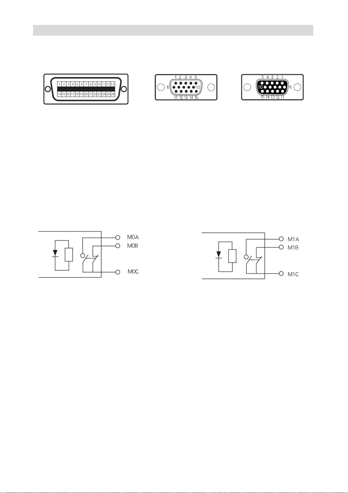
Connector terminal arrangement
T3 26-pin high density plug T4 D-type 15-pin plug (pin) T5 D-type 15-pin plug (hole)
Control power supply wiring
In addition to analog control terminal, all of other control terminals of GH series AC servo driver are
equipped with optocoupler isolation. Power of the optocoupler isolation may select from internal of the
driver or external power provided by the user according to the actual requirements. To ensure better
isolation effect, it is recommended to use external DC24V isolation power provided by user.
The wiring of relay output signal
GH AC servo driver provides two relay output points.
Output standard: AC250V 1A DC30V 1A
Accurate stop relay output schematic diagram Fault relay output schematic diagram
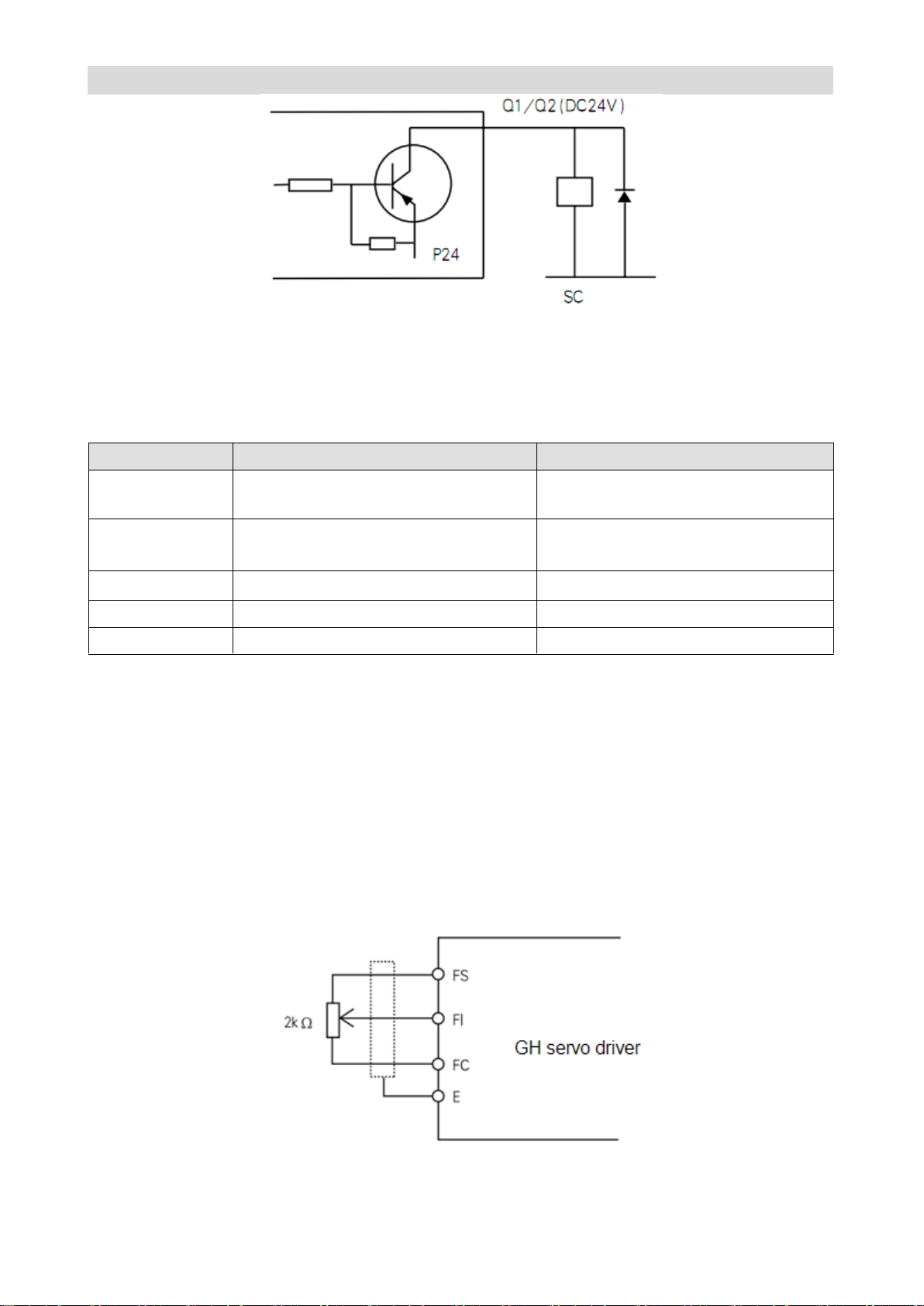
Transistor output wiring precautions
● The maximum oad capacity of output tape of transistor output QI/Q2 is 20 mA, and the output voltage
is DC24V.
● If the output terminal needs 0V, intermediate relay may be installed for switching as shown in Figure
2-14.
● If the output terminal drives inductive load (e.g., electromagnetic relay, intermediate relay), surge
voltage absorbing circuit shall be added as shown in Figure 2-14.
If follow current diode is installed in surge absorption circuit (for DC electromagnetic circuit), attention
must be paid to polarity during installation.
Page 46
CTB GH DRIVER
Signal
Function
Signal standard
FI
Unipolarity analog input terminal
A2-01=1
0~10V, input impedance: 20KΩ
FV
Bipolarity analog input terminal
A2-01=0
-10V~+10V analog input,
input impedance: 20KΩ
FS
inside provided speed setting power
DC10V,50mA,
Fc
analog common port
0V
E
Shielding layer connecting terminal
Figure 2-14 Transistor output circuit
Wiring of analog input signal
GH AC servo driver selects two analog input interfaces of FI and FV, as well as a group of power
interface FS and FC for analog input. Please see Table 2-9 for signal function description.
Table 2-9 Analog interface signal description
Wiring requirements
● Connect to signal source or control signal with multi-core shielded cable or stranded shielded wire.
● The near-end of shielding layer of the case (end near the driver) shall be connected to the connector
housing.
● During wiring, the control cables shall be arranged more than 30cm away from the main circuit and
strong power line (including power line, motor line, relay, contactor connecting cable), and avoid parallel
layout. Vertical wiring is recommended to prevent malfunction of the driver due to interference.
●Filter magnetic ring provided by the manufacturer shall be used for long distance wiring. It shall be
installed at the side near the driver.
FI terminal wiring example
Use internal power for speed setting. The input signal is 0 ~ 10V/4-20mA as shown in Figure 2-15.
Figure 2-15 Conduct speed setting with internal power
FV terminal wiring example
Page 47
GS DRIVER CTB
Forbid
● It's prohibited to connect the signal line and OV reversely. The signal line is likely to be burned, and
reverse operation may be caused for bipolar.
● It's prohibited to connect high-voltage to analog signal terminal. The driver may be burned.
Signal
Description
Signal standard
PV1
Encoder power supply DC5V
DC5V/200mA
G1
Encoder power ground 0V
A+
A phase PULSE same-phase input (+)
Line drive mode
RS422 standard
A-
A phase PULSE reverse -phase input (-)
B+
B phase PULSE same-phase input (+)
B-
B phase PULSE reverse -phase input (-)
Z+
Z phase PULSE same-phase input (+)
Z-
Z phase PULSE reverse-phase input (-)
T1
Motor thermal protection input terminal
NC/NO
Signal
Description
Signal standard
PV2
Encoder power supply DC5V
Or external
sensor power
supply
DC5V/200mA
Note: the connection is not required
when used as speed/position feedback
of the CNC system
G2
Encoder power ground 0V
OA+
A phase PULSE same-phase input (+)
Line drive mode
RS422 standard
OA-
A phase PULSE reverse-phase input (-)
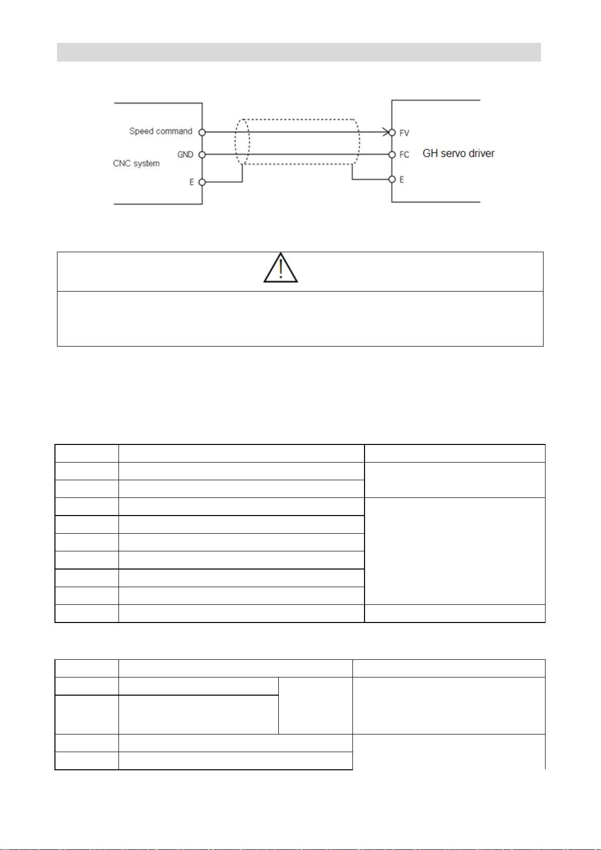
CNC system uses bipolar (-10V ~ +10 V) analog output. The speed is determined by the value of the
analog, the direction of rotation is determined by polarity of the analog as shown in Figure 2-16.
Figure 2-16 Bipolar speed setting is conducted by CNC system
Connection of the encoder interface
A group of encoder input interface T5 and encoder input interface T4 are provided on main board of GH
series AC servo driver. Please see Table 2-10 and Table 2-11 for interface definition.
Table 2-10 Encoder input interface T5
Table 2-11 Encoder output interface T4
Page 48

CTB GH DRIVER
OB+
B phase PULSE same-phase input (+)
OB-
B phase PULSE reverse-phase input (-)
OZ+
Z phase PULSE same-phase input (+)
OZ-
Z phase PULSE reverse-phase input (-)
SA+
Pulse/encoder A-phase input (+)
Line drive mode
RS422 standard
SA-
Pulse/encoder A-phase input (-)
PB+
Pulse/encoder B-phase input (+)
PB-
Pulse/encoder B-phase input (-)
DZ+
Pulse/encoder Z-phase input (+)
DZ-
Pulse/encoder Z-phase input (-)
Page 49
GS DRIVER CTB
Forbid
●It's prohibited to connect the DC5V power reversely. It's likely to burn the DC5V power or encoder of
the driver.
●It's prohibited to reverse the A, B phase sequence. Otherwise, the motor will not function properly, or
even burn the motor or driver.
Pin
Name
Description
Pin
Name
Description
1
VCC
DC5V
4
NC
Used by manufacturer
2
GND
0V
5
TX
Send terminal
3
RX
Receive terminal
6
NC
Used by manufacturer
Caution
● Please select the standard cable provided by the manufacturer for communication.
Encoder wiring precautions
● The encoder cable must be shielded twisted pair cable.
● The shielding layer shall be connected to the connector housing.
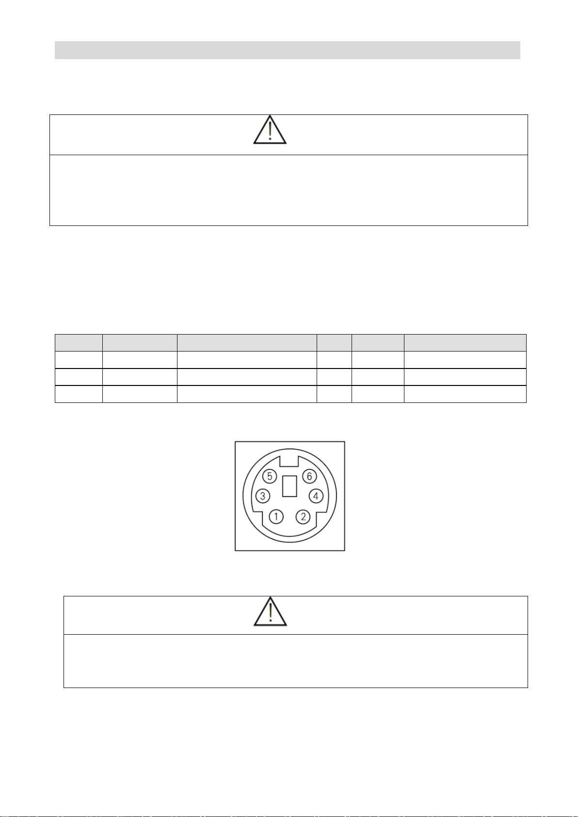
Connection of serial communication port
GH DRIVER provides users with a R S232A serial communication interface T0 for connection with
computer to realize transmission of program and parameters. The port is connected with computer
through RS232-P1 cable.
Please see Table 2-12 for definition of serial communication interface T0
Table 2-12 T0 interface definition
T0 interface diagram
General Purpose cable model: RS 232-p1
Page 50
CTB GH DRIVER
Manipulator application
The chapter describes the functions and methods of application of the
manipulator.
Digital tube display
0.4 ~ 18.5kw driver:
Configuration and key functions of the manipulator……………….3-2
Operative mode of the driver…………………………………………3-3
Operative mode of the manipulator………………………………….3-4
Use method of the manipulator………………………………………3-4
Modify the parameters with the manipulator………………………..3-5
Monitor operating state with the manipulator……………………….3-5
22 ~ 315kw driver:
Configuration and key functions of the manipulator………………..3-6
Operative mode of the driver…………………………………………3-8
Operative mode of the manipulator………………………………….3-8
Use method of the manipulator……………………………………...3-9
Modify the parameters with the manipulator……………………….3-9
Monitor operating state with the manipulator………………………3-10
Page 51

GS DRIVER CTB
LCD display
0.4 ~ 18.5kw driver:
Configuration and key functions of the manipulator……………….3-11
Operative mode of the driver…………………………………………3-12
Operative mode of the manipulator………………………………….3-12
Use method of the manipulator………………………………………3-13
Modify the parameters with the manipulator………………………..3-13
Monitor operating state with the manipulator……………………….3-14
22 ~ 315kw driver:
Configuration and key functions of the manipulator………………..3-15
Operative mode of the driver…………………………………………3-17
Operative mode of the manipulator………………………………….3-17
Use method of the manipulator……………………………………...3-18
Modify the parameters with the manipulator……………………….3-18
Monitor operating state with the manipulator………………………3-19
Page 52
CTB GH DRIVER
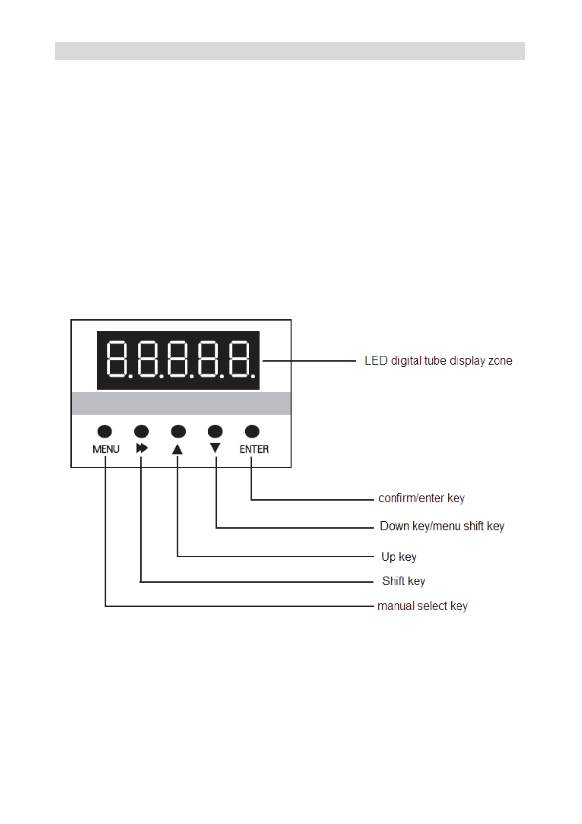
Configuration and key functions of the 0.4 ~ 18.5kw driver digital tube manipulator
The chapter defines and describes terms and phrases for operation and state of 0.4 ~ 18.5kw driver
manipulator, defines the operation methods of driver and manipulator. Please read carefully. It's very
helpful for proper use of the 0.4 ~ 15kw driver.
Manipulator
The manipulator is one of the standard equipment of 0.4 ~ 18.5kw driver. User may carry out parameter
setting, state monitoring, operation control and other operations to the driver through the manipulator. It's
very important to be familiar with function and operation of the manipulator for proper application of 0.4 ~
18.5kw series driver. Please read the manual carefully before using.
Manipulator appearance diagram
Manipulator of 0.4 ~ 18.5kw driver is mainly composed of two parts of LED digital tube and keys. The
appearance and functional zones are shown in Figure 3-1.
Figure 3-1 Manipulator diagram
Page 53
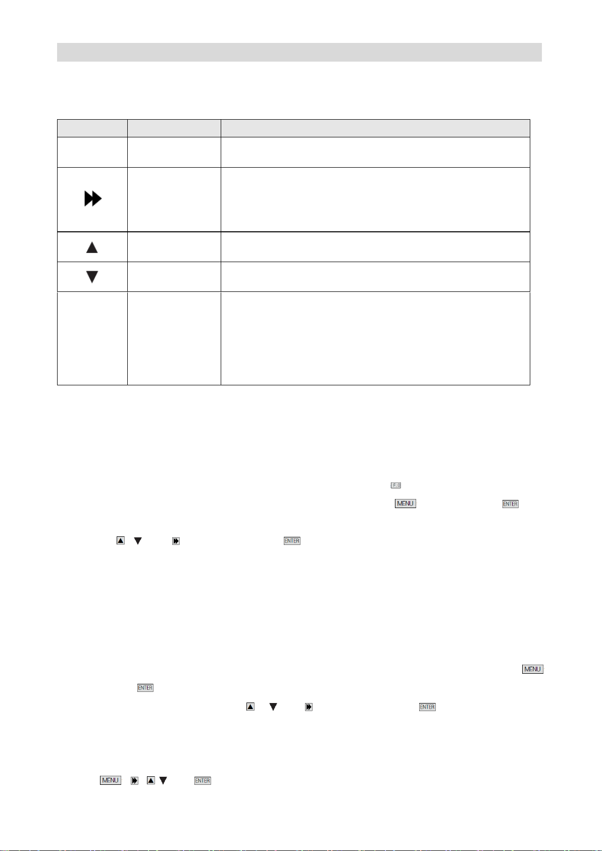
GS DRIVER CTB
Key
Name
Function
Menu
Menu selection
switching key
switching key of each menu item;
Shift key
It's used to switch data bit of the parameter number when browse
parameter items;
When modifying data in program state, it can be used to modify
the modified bit of the modified data.
up key
Increase menu item, parameter item or modified parameter value
progressively.
down key
Decrease menu item, parameter item or modified parameter
value progressively.
Enter
Confirm / enter key
Press the key in program state to return to the previous menu.
Enter the next level menu;
Complete selection of the parameter group in1-level menu;
Complete parameter value checking operation in 2-level menu;
Complete modification and storage operation of the parameter
value in 3-level menu;
Manipulator key function description
Please see Table 3-1 for function description of the manipulator key
Table 3-1 Manipulator key function
The operating state of the driver
0.4 ~ 18.5kw driver has four operating states after power-on: standby, operating, programming and fault
alarm. They are described as follows:
Standby state
0.4 ~ 18.5kw driver is in standby state after power-on and before receiving any operating control order.
The default standby state display function code of LED digital tube is . User may make LED circling
switch display U1, U2, U3, A1, A2 and A3 parameter groups by press key. After press key,
user may make LED circling switch display monitoring parameters defined in function parameter group
by pressing , and key, and then press key to check /monitor its value.
It will be limited by functional parameter A1.00 when user want to check / modify the content of
parameter groups other than U1, U2, U3, A1, A2 and A3 during operation. All of the parameters may be
checked when A1.00=1.
Operating state
When 0.4 ~ 18.5kw driver in standby and no-fault state, it will enter operating state after receiving
operating order.
User may make LED circling switch display U1, U2, U3, A1, A2 and A3 parameter groups by press
key. After press key, user may make LED circling switch display monitoring parameters defined in
function parameter groups by pressing , .and key, and then press key to check /monitor
its value.
Setting, modifying or editing state
For 0.4 ~ 18.5kw driver, user may switch to the state in which function code parameters can be modified
through , , , .and on the operator panel. The state is programming state.
Page 54
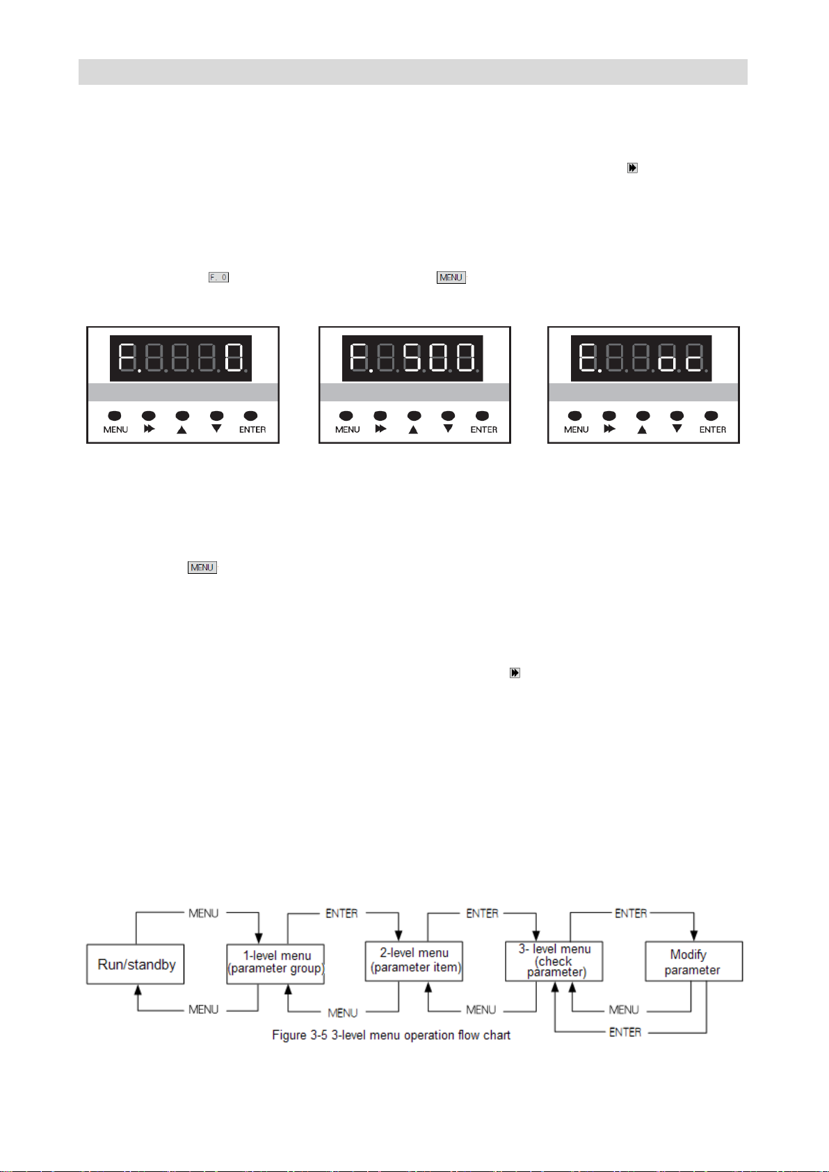
CTB GH DRIVER
Function parameter value is displayed in programming state, and the bit to be modified is flashing.
Fault alarm state
In the state, 0.4 ~ 18.5kw driver fails and displays the fault code.
LED displays fault code in fault state, and user may conduct fault reset operation by ,.
Operative mode of the manipulator
Standby state:
The state of the manipulator is shown in Figure 3-2 when the driver is in standby state. The LED digital
tube default display . At this point, user may press to enter menu items, and check or modify
parameters.
Figure 3-2 Standby state Figure 3-3 Operating state Figure 3-4 Fault alarm state
Operating state:
The driver enters operating state after receiving correct operation command in standby state. As shown
in Figure 3-3, the LED digital tube default displays the set speed of the driver, e.g F. 500. In this state,
user may press to enter menu items, and check or modify parameters.
Fault alarm state
When fault is detected as the driver is in operating, standby or programming state, the driver will stop
and enter fault state immediately as shown in Figure 3-4.
When a fault occurs, user may enable conduct drive reset through key. If the fault has disappeared, it
returns to the standby state; if the fault still exists, the fault code will be displayed again.
Use method of the manipulator
The section mainly introduces use of the manipulator, and basic operations of functions.
Parameter setting operation process
Parameter setting method of manipulator of 0.4 ~ 18.5kw driver adopts three-level menu structure.
Parameter value of menu items can be checked and modified conveniently.
The three-level menu: menu item (1-level menu), parameter tem (2-level menu) and parameter setting
(3-level menu). The operation process is shown in Figure 3-5.
Page 55
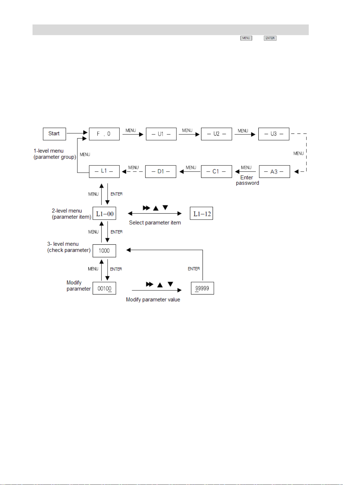
GS DRIVER CTB
During operation in 3-level menu, user may return to 2-level menu by pressing or (see Figure
3-5 and Figure 3-6). The difference between the two operations: after press ENTER key, the set
parameter value will be saved to the controller, and then return to 2-level menu; it will return to 2-level
menu directly without saving the parameter value by pressing MENU. The detail operational procedures
of 3-level menu are shown in Figure 3-6.
Modify the parameters with the manipulator
The flow chart of modify the parameters with the manipulator is shown in Figure 3-6.
★ Description:
Ten menu items are included in 1-level menu: U1menu, U2 menu, U3 menu, A1 menu, A2 menu, A3
menu, C1 menu, D1 menu, E1 menu, P1 menu, T1 menu and L1 menu.
Please see parameter description for specific functions in 2-level menu.
Monitor operating state with the manipulator
Operation state, interface state and fault information of the driver can be monitored respectively through
U1, U2 and U3 of the manipulator
Operation state monitoring
Operation state monitoring includes set speed F, output speed O, feedback speed b, output current A,
output torque T and DC bus voltage U of the driver. Please see Figure 3-7 for monitoring method.
Page 56
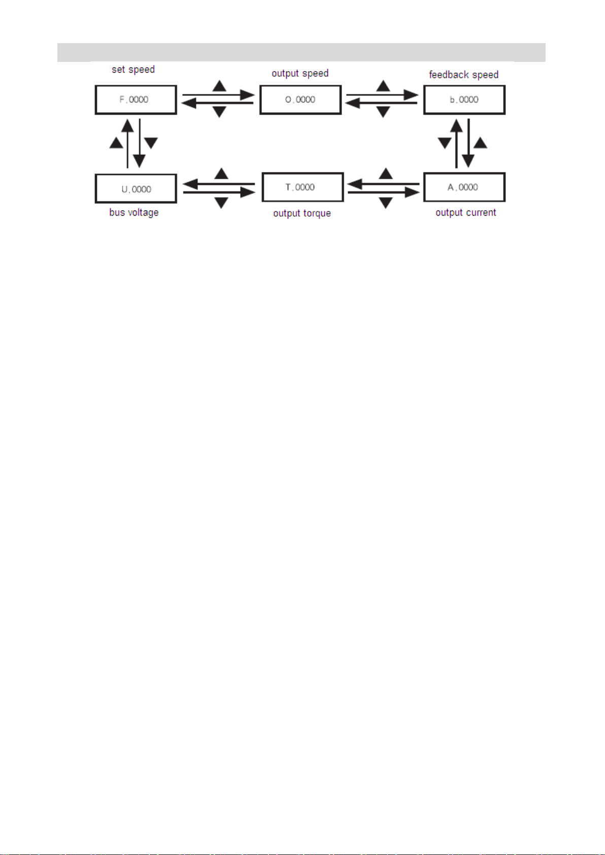
CTB GH DRIVER
Figure 3-7 Driver operation state monitoring flowchart
Interface state monitoring
Interface state includes driver’s encoder input interfaces U2-00, U2-01; switching value input terminals
U2-02, U2-03; switching value output terminal U2-04, analog input interfaces U2-05, U2-06; output
terminals U2-07, U2-08. The monitoring method is same with monitoring parameter, only needs to select
corresponding parameter in U2. Please see U2 parameter monitoring table 2 for parameter number.
Fault information monitoring
The control panel will display the current fault message code when the driver is in fault state. The fault
record of the driver can be checked through U3. The check operation is same with monitoring parameter,
only needs to select corresponding parameter in U3. Please see fault state recording parameter table U3
for parameter number.
22~315k w driver: Configuration and key functions of the 22~315kw driver digital
tube manipulator
The chapter defines and describes terms and phrases for operation and state of 22~315kw driver
manipulator, defines the operation methods of the driver and manipulator. Please read carefully. It's very
helpful for proper use of the 22~315kw driver.
Manipulator
The manipulator is one of the standard equipment of 22~315kw driver. User may carry out parameter
setting, state monitoring, operation control and other operations to the driver through the manipulator. It's
very important to be familiar with function and operation of the manipulator for proper application of 22~
315kw series driver. Please read the manual carefully before using.
Manipulator appearance diagram
Manipulator of 22~315kw driver is mainly composed of three parts of LED digital tube, LED indicator
and key. The appearance and functional zones are shown in Figure 3-8.
Page 57
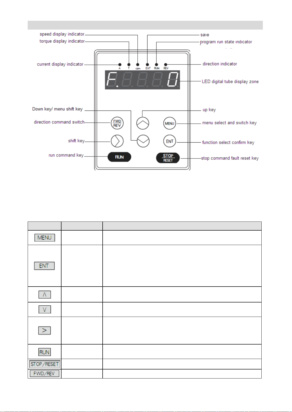
GS DRIVER CTB
Key
Name
Function
Menu select and
switch key
switching key of each menu item;
Confirm / enter
key
Press the key in program state to return to the previous menu.
Enter the next level menu;
Complete selection of the parameter group in 1-level menu;
Complete parameter value checking operation in 2-level menu;
Complete modification and storage operation of the parameter value
in 3-level menu;
up key
Increase menu item, parameter item or modified parameter value
progressively.
down key
Decrease menu item, parameter item or modified parameter value
progressively.
Shift key
It's used to switch data bit of the parameter number when browse
parameter items.
It may change the bit to be modified of the modified data when modify
data in the program state.
run command
key
It's used to start the driver in driver control mode;
fault reset key
It's used to reset driver reset when the driver is in fault alarm state.
direction
It's used to select rotation direction of the driver in manipulator
Figure 3-8 Manipulator diagram
Manipulator key function description
Please see Table 3-2 for function description of the manipulator key
Table 3-2 Manipulator key function
Page 58

CTB GH DRIVER
command switch
key
command control mode.
Manipulator LED indicator description
There are six LED indicators on the manipulator. They are on or off in various states. The detail
description is as follows:
Current display indicator A:
It has two states of on and off which indicates that the data displayed in the current LED digital tube
display zone is current parameter or not. On means current parameter is displayed in the LED digital
tube display zone; off means that it's not current parameter displayed in the LED digital tube display
zone.
Torque display indicator T:
It has two states of on and off which indicates that the data displayed in the current LED digital tube
display zone is torque parameter or not. On means torque parameter is displayed in the LED digital tube
display zone; off means that it's not torque parameter displayed in the LED digital tube display zone.
Speed display indicator rpm:
It has two states of on and off which indicates that the data displayed in the current LED digital tube
display zone is speed parameter or not. On means speed parameter is displayed in the LED digital tube
display zone; off means that it's not speed parameter displayed in the LED digital tube display zone.
Indicator EXT
Save;
Run state indicator RUN:
It has two states of on and off which indicates the run state of the system under various operating control
orders. On means the driver is in operating state; off means the driver is shutdown.
Operating direction indicator REV:
It has two states of on and off which indicates the current operating direction of the driver. On means
reverse operation of the driver; off means forward operation of the driver.
The operating state of the driver
22~315kw driver has four operating states after power-on: standby, operating, setting, modifying or
editing and fault alarm. They are described as follows:
Standby state
22~315kw driver is in standby state after power-on and before receiving any operating control order.
The Run state indicator (RUN) on operation panel is off, and the default tandby state display function
code of LED digital tube is . User may make LED circling switch display U1, U2, U3, A1,2 A2 and A3
parameter groups by press key.After pressing ENT to make LED circling switch display
monitoring parameters defined in function parameter group, and then press ENT to check /monitor its
value.
It will be limited by selection functional parameter A1-00=1 when the user wants to check / modify the
content of parameter groups other than U1, U2, U3, A1,2 A2 and A3 during operation. All of the
parameters may be checked with A1-00=1.
Operating state
Page 59
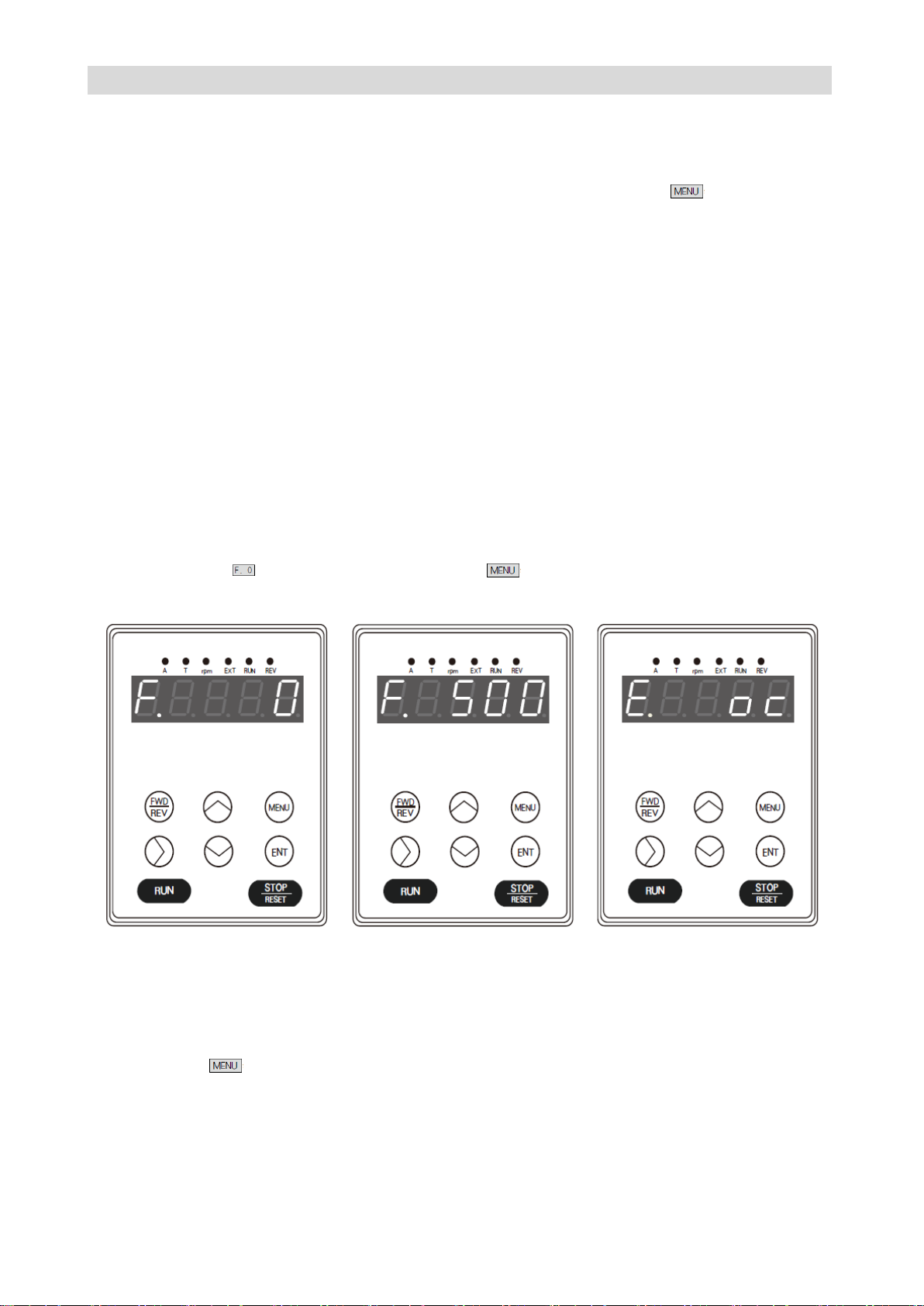
GS DRIVER CTB
When 22~315kw driver in standby and no-fault state, it will enter operating state after receiving
operating order.
In normal operating state, the Run state indicator (RUN) on operation panel is on. User may make LED
circling switch display U1, U2, U3, A1,2 A2 and A3 parameter groups by press key. Press ∧,∨
and > after pressing ENT to make LED circling switch display monitoring parameters defined in function
parameter groups, and then press ENT to check /monitor its value.
Setting, modifying and editing state
For 22~315kw driver, user may switch to the state in which function code parameters can be modified
through MENU, ENT, ∧, ∨and > on the operator panel. The state is programming state.
Function parameter value is displayed in programming state, and the bit to be modified is flashing.
Fault alarm state
In the state, 22~315kw driver fails and displays the fault code.
LED displays fault code in fault state, and > may enable user conducting fault reset operation.
Operative mode of the manipulator
Standby state:
The state of the manipulator is shown in Figure 3-9 when the driver is in standby state. The LED digital
tube default display . At this point, user may press to enter menu items, and check or modify
parameters.
Figure 3-9 Standby state Figure 3-10 Operating state Figure 3-11 Fault alarm state
Operating state:
The driver enters operating state after receiving correct operation command in standby state. As shown
in Figure 3-10, the LED digital tube default displays the set speed of the driver, e.g F. 500. In this state,
user may press to enter menu items, and check or modify parameters.
Fault alarm state
When fault is detected as the driver is in operating, standby or programming state, the corresponding
fault information will be displayed immediately as shown in Figure 3-11.
When a fault occurs, the driver may enable driver reset through >. If the fault has disappeared, it returns
Page 60
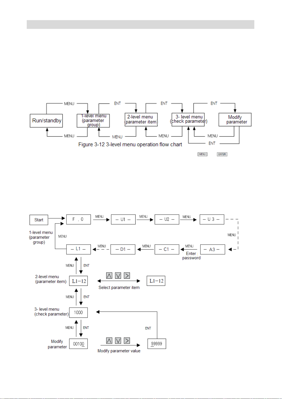
CTB GH DRIVER
to the standby state; if the fault still exists, the fault code will be displayed again.
Use method of the manipulator
The section mainly introduces use of the manipulator, and basic operations of functions.
Parameter setting operation process
Parameter setting method of manipulator of 22~315kw driver adopts three-level menu structure.
Parameter value of menu items can be checked and modified conveniently.
The three-level menu: menu item (1-level menu), parameter tem (2-level menu) and parameter setting
(3-level menu). The operation process is shown in Figure 3-12.
During operation in 3-level menu, user may return to 2-level menu by pressing or (see Figure
3-12 and Figure 3-13). The difference between the two operations: after press ENTER key, the set
parameter value will be saved to the controller, and then return to 2-level menu; it will return to 2-level
menu directly without saving the parameter value by pressing MENU. The detail operational procedures
of 3-level menu are shown in Figure 3-13.
Modify the parameters with the manipulator
The flow chart of modify the parameters with the manipulator is shown in Figure 3-13.
Figure 3-13 3-level menu operation flow chart
Page 61
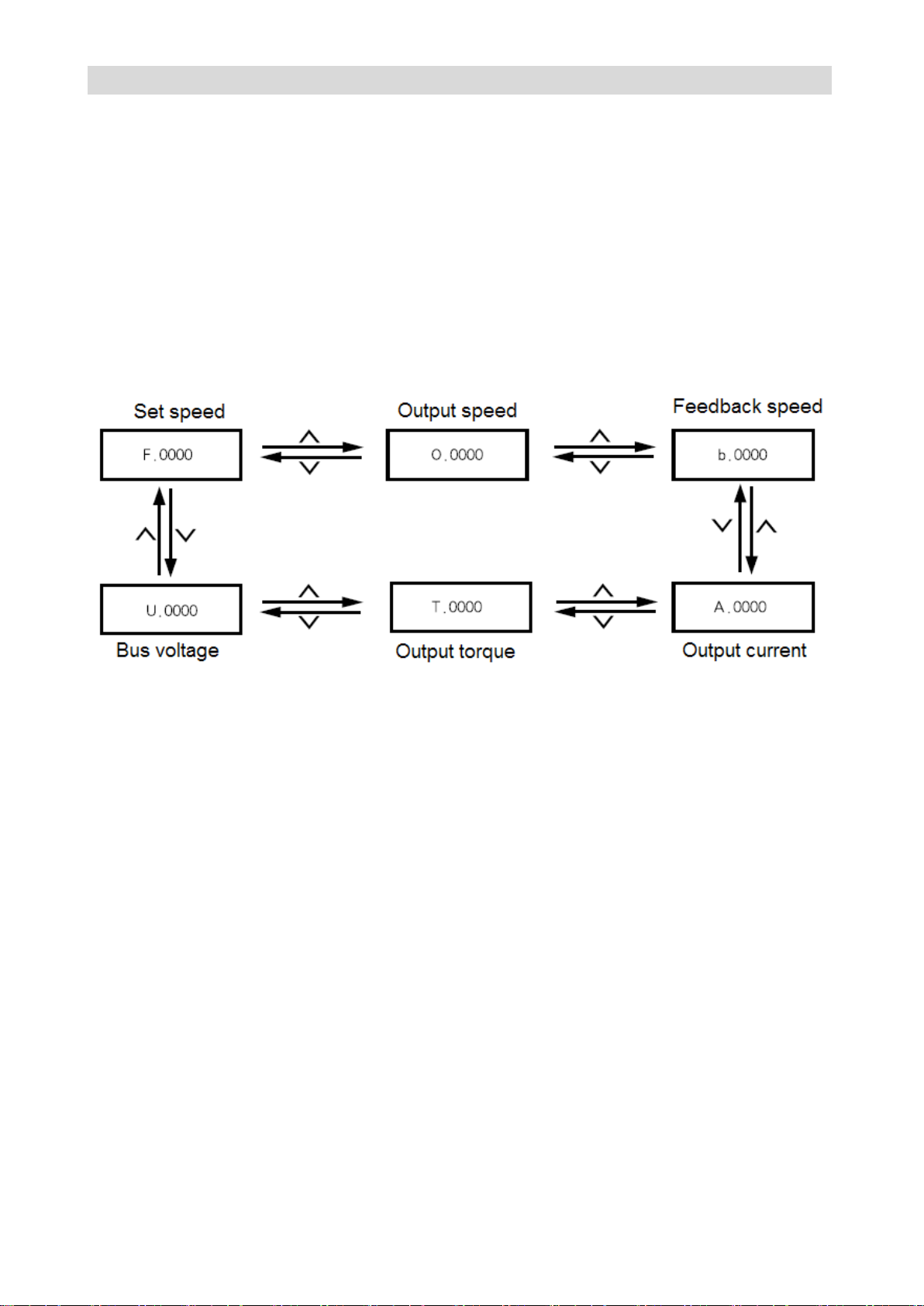
GS DRIVER CTB
★ Description:
10 menu items are included in 1-level menu: U1menu, U2 menu, U3 menu, A1 menu, A2 menu, A3
menu, C1 menu, D1 menu, E1 menu, P1 menu, T1 menu and L1 menu.
Please see parameter description for detailed function in 2-level menu.
Monitor operating state with the manipulator
Operation state, interface state and fault information of the driver can be monitored respectively through
U1, U2 and U3 of the manipulator
Operation state monitoring
Operation state monitoring includes set speed F, output speed O, feedback speed b, output current A,
output torque T and DC bus voltage U of the driver. Please see Figure 3-14 for monitoring method.
Figure 3-14 Driver operation state monitoring flowchart
Interface state monitoring
Interface state includes driver’s encoder input interfaces U2-00, U2-01; switching value input terminals
U2-02, U2-03; switching value output terminal U2-04, analog input interfaces U2-05, U2-06; output
terminals U2-07, U2-08. The monitoring method is the same as monitoring parameter, only needs to
select corresponding parameter in U2. Please see U2 parameter monitoring table 2 for parameter
number.
Fault information monitoring
The control panel will display the current fault message code when the driver is in fault state. The fault
record of the driver can be checked through U3. The check operation is the same as monitoring
parameter, only needs to select corresponding parameter in U3. Please see parameter table of
parameter number.
Configuration and key functions of the 0.4~18.5kw driver LCD manipulator
The chapter defines and describes terms and phrases for operation and state of 0.4~18.5kw driver
manipulator, defines the operation methods of the driver and manipulator. Please read carefully. It's very
helpful for proper use of the 0.4~18.5kw driver.
Page 62
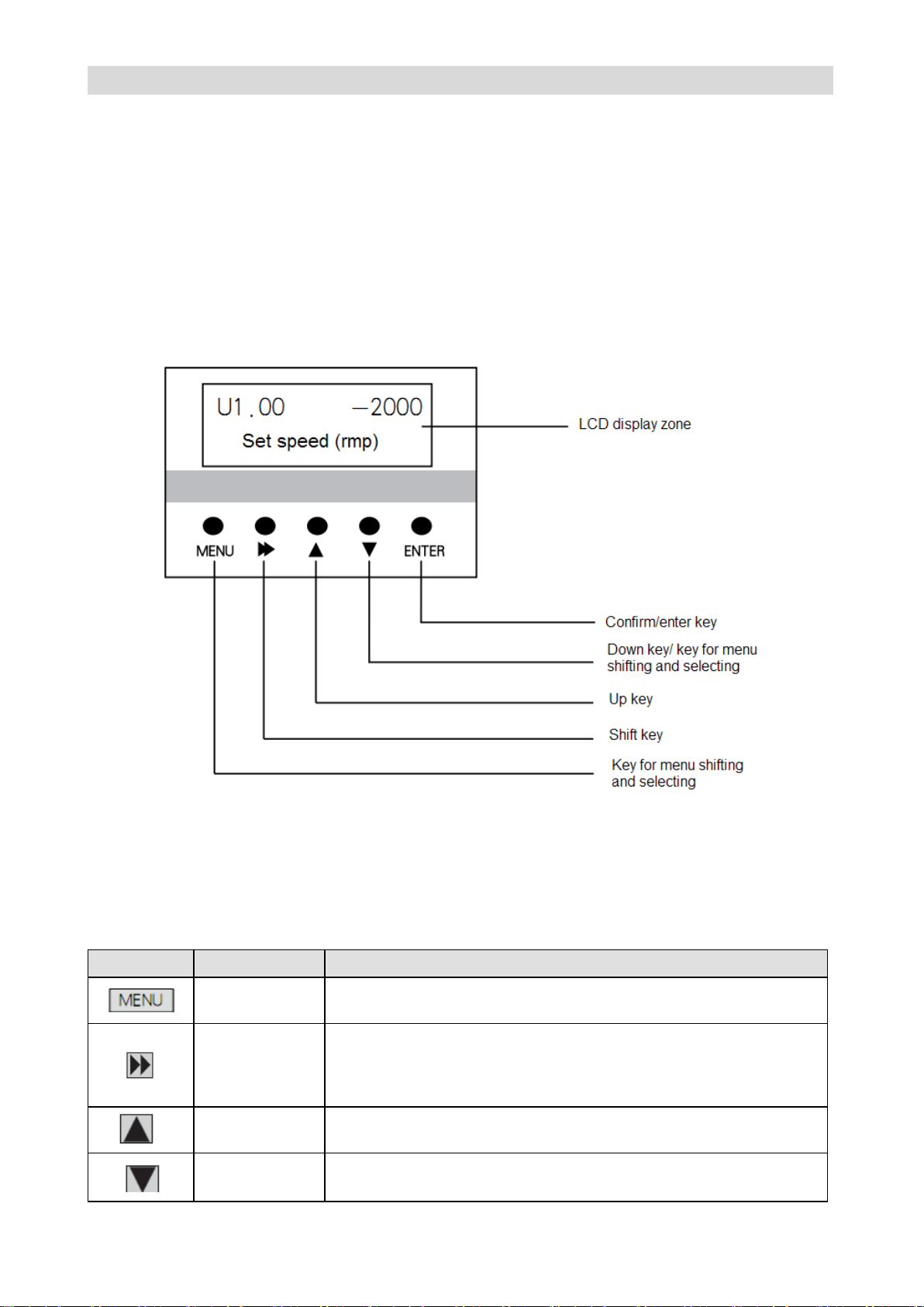
CTB GH DRIVER
Key
Name
Function
Menu select and
switch key
switching key of each menu item;
Shift key
It's used to switch data bit of the parameter number when browse
parameter items; The low order of the data may be displayed when
displaying 32-bit data. When modifying data in program state, it can
be used to modify the modified bit of the modified data.
up key
Increase menu item, parameter item or modified parameter value
progressively.
down key
Decrease menu item, parameter item or modified parameter value
progressively;shift among monitoring menu and menu item.
Manipulator
The manipulator is one of the standard equipment of 0.4~18.5kw driver. User may carry out parameter
setting, state monitoring, operation control and other operations to the driver through the manipulator. It's
very important to be familiar with function and operation of the manipulator for proper application of 0.4~
18.5kw series driver. Please read the manual carefully before using.
Manipulator appearance diagram
Manipulator of 0.4~18.5kw driver is mainly composed of two parts of LCD display zone and keys. The
appearance and functional zones are shown in Figure 3-15.
Figure 3-15 PO-S6 Manipulator diagram
Manipulator key function description
Please see Table 3-3 for function description of the manipulator key
Table 3-3 Manipulator key function
Page 63

GS DRIVER CTB
Confirm / enter
key
Press the key in menu state to enter parameter modifying interface;
Complete modification and storage operation of the parameter value
in the parameter modifying interface.
The operating state of the driver
0.4~18.5kw driver has four operating states after power-on: standby, operating, programming and fault
alarm. They are described as follows:
Standby state
0.4~18.5kw driver is in standby state after power-on and before receiving any operating control order.
The default standby state display function code of LCD digital tube is . User may make LCD circling
switch display U1, U2. U3, A1, A2 and A3 monitoring function parameter groups by pressing MENU key.
Press , and after pressing to make LCD circling switch display monitoring
parameters defined in function parameter group, and may check/monitor the value. Then press to
modify its value.
It will be limited by selection functional parameter A1-00 when user want to check / modify the content of
parameter groups other than U1, U2. U3, A1, A2 and A3 during operation. All of the parameters may be
checked with A1-00=1.
Operating state
When 0.4~18.5kw driver in standby and no-fault state, it will enter operating state after receiving
operating order.
User may make LCD circling switch display U1, U2. U3, A1, A2 and A3 monitoring function parameter
groups by pressing MENU key. Press , and after pressing to make LCD circling
switch display monitoring parameters defined in function parameter group, and may check/monitor the
value. Then press to modify its value.
Setting, modifying and editing state
For 0.4~18.5kw driver, user may switch to the state in which function code parameters can be modified
through MENU, , , and ENTER on the operator panel. The state is programming state.
Function parameter value is displayed in programming state, and the bit to be modified is displayed in
inverse color.
Fault alarm state
In the state, 0.4~18.5kw driver fails and displays the fault code.
LCD displays fault code in fault state, and may enable user conducting fault reset operation.
Operative mode of the manipulator
Standby state:
The state of the manipulator is shown in Figure 3-16 when the driver is in standby state. The LCD digital
tube default display . At this point, user may press to enter menu items, and check or modify
parameters.
Page 64
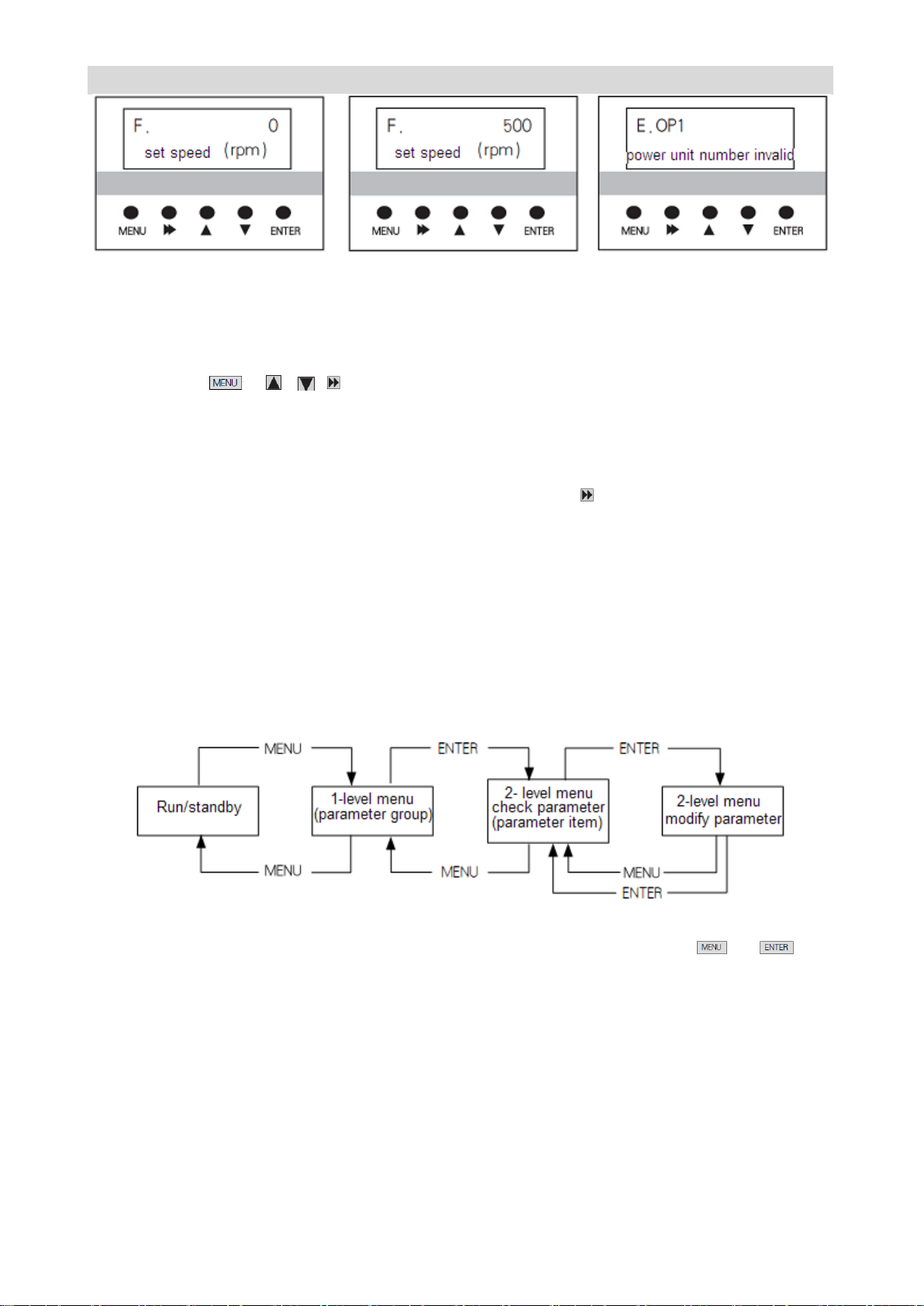
CTB GH DRIVER
Figure 3-16 Standby state Figure 3-17 Operating state Figure 3-18 Fault alarm state
Operating state:
The driver enters operating state after receiving correct operation command in standby state. As shown
in Figure 3-17, the LCD digital tube default displays the set speed of the driver, e.g F. 500. In this state,
user may press , , , and ENTER to enter menu items, and check or modify parameters.
Fault alarm state
When fault is detected as the driver is in operating, standby or programming state, the corresponding
fault information will be displayed immediately as shown in Figure 3-18.
When a fault occurs, the driver may enable driver reset through . If the fault has disappeared, it
returns to the standby state; if the fault still exists, the fault code will be displayed again.
Use method of the manipulator
Parameter setting operation process
Parameter setting method of manipulator adopts three-level menu structure. Parameter value of menu
items can be checked and modified conveniently.
The three-level menu: menu item (1-level menu), parameter tem (2-level menu) and parameter setting
(3-level menu). The operation process is shown in Figure 3-19.
Figure 3-19 2-level menu operation flow chart
During operation in 2-level menu, user may return to 2-level menu by pressing or . The
difference between the two operations: after press ENTER key, the set parameter value will be saved to
the controller, and then return to 2-level menu; it will return to 2-level menu directly without saving the
parameter value by pressing MENU. The detail operational procedures of 2-level menu are shown in
Figure 3-20.
Modify the parameters with the manipulator
The flow chart of modify the parameters with the manipulator is shown in Figure 3-20.
Page 65
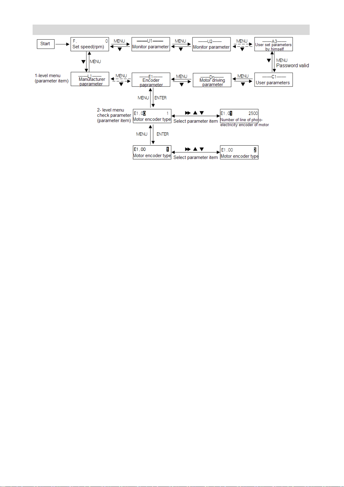
GS DRIVER CTB
Figure 3-20 2-level menu operation flow chart
Page 66
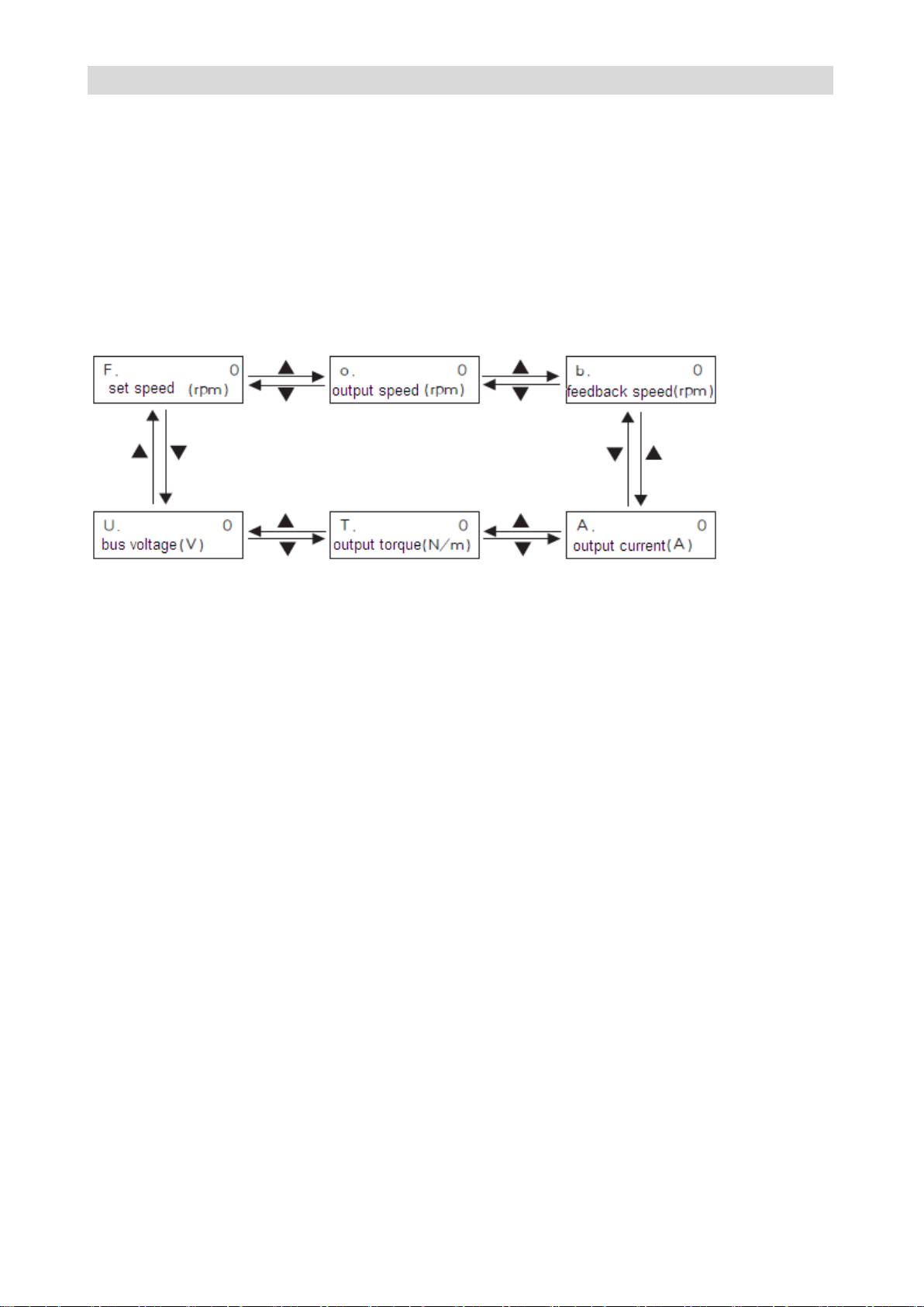
CTB GH DRIVER
★ Description:
10 menu items are included in 1-level menu: U1 menu, U2 menu, U3 menu, A1 menu, A2 menu, A3
menu, C1 menu, D1 menu, E1 menu, P1 menu, T1 menu and L1 menu.
Please see parameter description for detailed function in 2-level menu.
Monitor operating state with the manipulator
Operation state, interface state and fault information of the driver can be monitored respectively through
U1, U2 and U3 of the manipulator
Operation state monitoring
Operation state monitoring includes set speed F, output speed O, feedback speed b, output current A,
output torque T and DC bus voltage U of the driver. Please see Figure 3-21 for monitoring method.
Figure 3-21 Driver operation state monitoring flowchart
Interface state monitoring
Interface state includes driver’s encoder input interfaces U2-00, U2-01; switching value input terminals
U2-02, U2-03; switching value output terminal U2-04, analog input interfaces U2-05, U2-06; output
terminals U2-07, U2-08. The monitoring method is same with monitoring parameter, only needs to select
corresponding parameter in U2. Please see U2 parameter monitoring table 2 for parameter number.
Fault information monitoring
The control panel will display the current fault message code when the driver is in fault state. The fault
record of the driver can be checked through U3. The check operation is same with monitoring parameter,
only needs to select corresponding parameter in U3. Please see fault state recording parameter table U3
for parameter number.
Configuration and key functions of the 22~315kw driver LCD
manipulator
The chapter defines and describes terms and phrases for operation and state of 22~315kw driver
manipulator, defines the operation methods of the driver and manipulator. Please read carefully. It's very
helpful for proper use of the 22~315kw driver.
Manipulator
The manipulator is one of the standard equipment of 22~315kw driver. User may carry out parameter
setting, state monitoring, operation control and other operations to the driver through the manipulator. It's
very important to be familiar with function and operation of the manipulator for proper application of 22~
315kw series driver. Please read the manual carefully before using.
Manipulator appearance diagram
Manipulator of 22~315kw driver is mainly composed of three parts of LED indicator, LCD display zone
and keys. The appearance and functional zones are shown in Figure 3-22.
Page 67
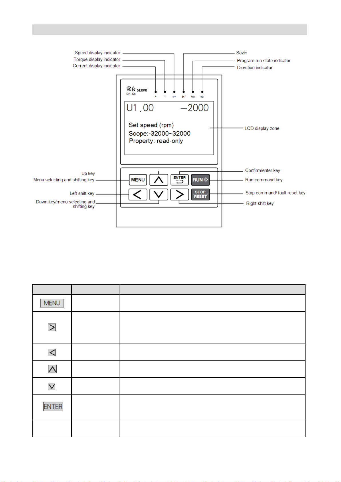
GS DRIVER CTB
Key
Name
Function
Menu select and
switch key
Switching key of each menu item;
Right shift key
It's used to switch data bit of the parameter number when browse
parameter items;
It's used to change the modified bit of the modified data when change
parameter.
left shift key
It's used to change the modified bit of the modified data when change
parameter.
up key
Increase menu item, parameter item or modified parameter value
progressively.
down key
Decrease menu item, parameter item or modified parameter value
progressively.
Confirm / enter
key
Press the key in menu state to enter parameter modifying interface;
Complete modification and storage operation of the parameter value
in the parameter modifying interface.
STOP/RESE
T
Fault reset key
It's used for reset of driver fault when the driver is in fault alarm state.
Figure 3-22 PO-S8 Manipulator diagram
Manipulator key function description
Please see Table 3-4 for function description of the manipulator key
Table 3-4 Manipulator key function
Page 68
CTB GH DRIVER
FWD/REV
Direction
command switch
key
It's used to select the run operation of the driver when the driver is in
command control mode; the key indicator automatically displays the
run direction of the driver during terminal control.
Manipulator LED indicator description
There are six LED indicators on the manipulator. They are on or off in various states. The detail
description is as follows:
Current display indicator A:
It has two states of on and off which indicates that the data displayed in the current LCD display zone is
current parameter or not. On means current parameter is displayed in the LCD display zone; off means
that it's not current parameter displayed in the LCD display zone.
Torque display indicator T:
It has two states of on and off which indicates that the data displayed in the current LCD display zone is
torque parameter or not. On means torque parameter is displayed in the LCD display zone; off means
that it's not torque parameter displayed in the LCD display zone.
Speed display indicator rpm:
It has two states of on and off which indicates that the data displayed in the current LCD display zone is
speed parameter or not. On means speed parameter is displayed in the LCD display zone; off means
that it's not speed parameter displayed in the LCD display zone.
Indicator EXT
Save;
Run state indicator RUN:
It has two states of on and off which indicates the run state of the system under various operating control
orders. On means the driver is in operating state; off means the driver is shutdown.
Operating direction indicator REV:
It has two states of on and off which indicates the current operating direction of the driver. On means
reverse operation of the driver; off means forward operation of the driver.
The operating state of the driver
22~315kw driver has four operating states after power-on: standby, operating, programming and fault
alarm. They are described as follows:
Standby state
22~315kw driver is in standby state after power-on and before receiving any operating control order.
The default standby state display function code of LCD is . User may make LCD circling switch
display U1, U2,U3, A1, A2 and A3 monitoring function parameter groups by pressing MENU key. Press
∧, ∨, > and < after pressing to make LCD circling switch display monitoring parameters
defined in function parameter group, and may check/monitor the value. Then press to modify its
value.
It will be limited by selection functional parameter A1.00 when user want to check / modify the content of
Page 69
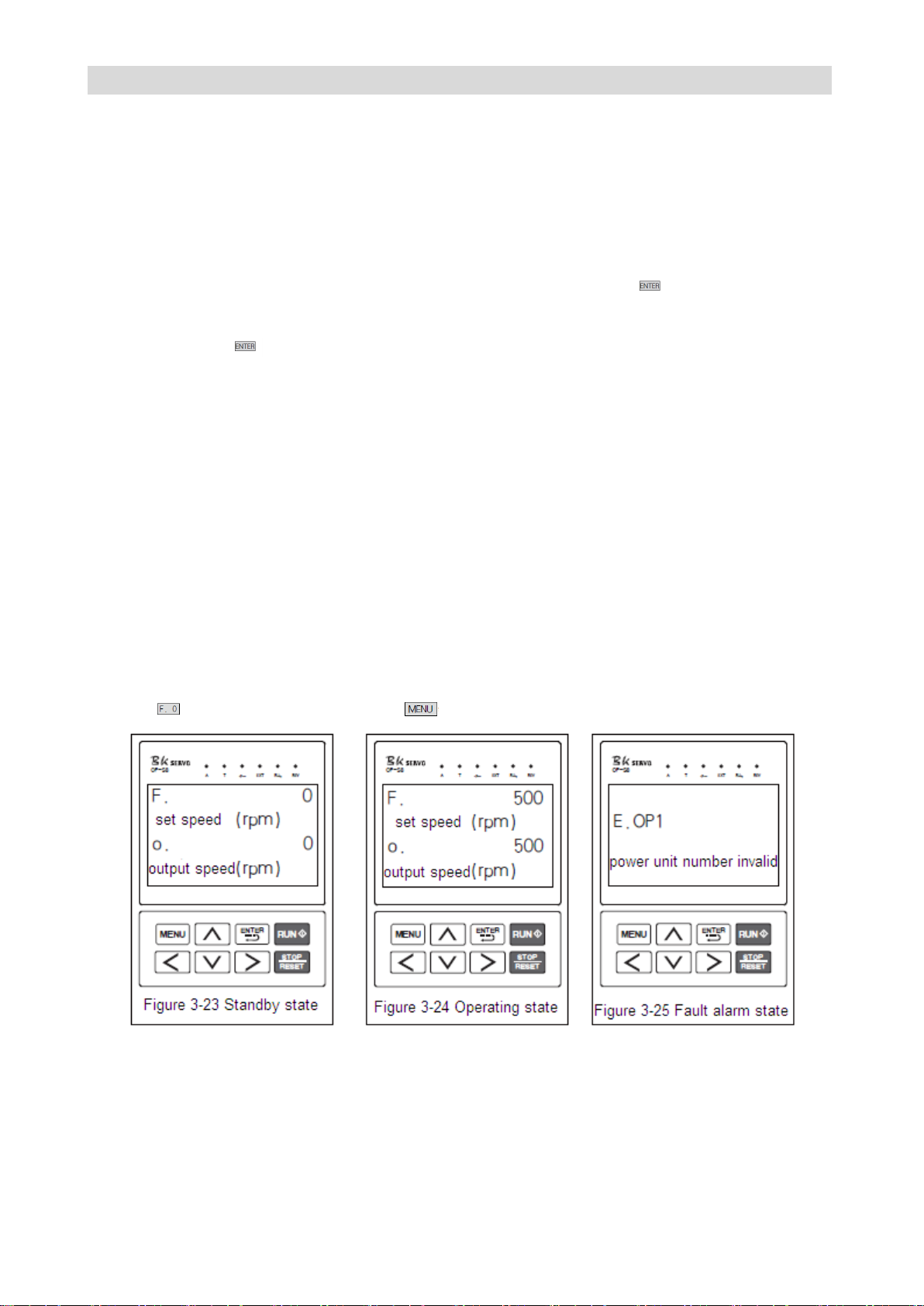
GS DRIVER CTB
parameter groups other than U1, U2,U3, A1, A2 and A3 during operation. All of the parameters may be
checked with A1-00=1.
Operating state
When 22~315kw driver in standby and no-fault state, it will enter operating state after receiving
operating order.
User may make LCD circling switch display U1, U2,U3, A1, A2 and A3 monitoring function parameter
groups by pressing MENU key. Press ∧, ∨, > and < after pressing to make LCD circling
switch display monitoring parameters defined in function parameter group, and may check/monitor the
value. Then press to modify its value.
Setting, modifying and editing state
For 22~315kw driver, user may switch to the state in which function code parameters can be modified
through MENU, ENTER, ∧, ∨, > and < on the operator panel. The state is programming state.
Function parameter value is displayed in programming state, and the bit to be modified is displayed in
inverse color.
Fault alarm state
In the state, 22~315kw driver fails and displays the fault code.
LCD displays fault code in fault state, and > may enable user conducting fault reset operation.
Operative mode of the manipulator
Standby state:
The state of the manipulator is shown in Figure 3-23 when the driver is in standby state. The LCD default
displays . At this point, user may press to enter menu items, and check or modify parameters.
Operating state:
The driver enters operating state after receiving correct operation command in standby state. As shown
in Figure 3-24, the LCD digital tube default displays the set speed of the driver, e.g F. 500. In this state,
user may press MENU, ENTER, ∧, ∨, > and < to enter menu items, and check or modify
parameters.
Page 70
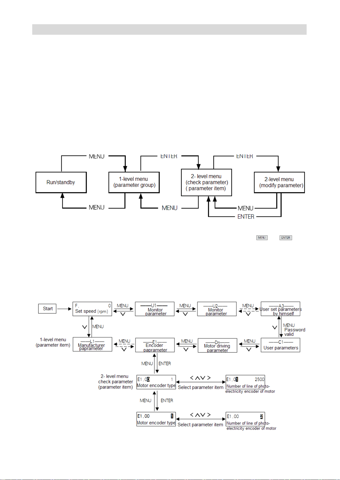
CTB GH DRIVER
Fault alarm state
When fault is detected as the driver is in operating, standby or programming state, the corresponding
fault information will be displayed immediately as shown in Figure 3-25.
When a fault occurs, the driver may enable driver reset through disconnection. If the fault has
disappeared, it returns to the standby state; if the fault still exists, the fault code will be displayed again.
Use method of the manipulator
Parameter setting operation process
Parameter setting method of manipulator adopts 2-level menu structure. Parameter value of menu items
can be checked and modified conveniently.
The 2-level menu: menu item (1-level menu), parameter and parameter setting value tem (2-level menu).
The operation process is shown in Figure 3-26.
Figure 3-26 2-level menu operation flow chart
During operation in 2-level menu, user may return to 2-level menu by pressing or . The
difference between the two operations: after press ENTER key, the set parameter value will be saved to
the controller, and then return to 2-level menu; it will return to 2-level menu directly without saving the
parameter value by pressing MENU. The detail operational procedures of 2-level menu are shown in
Figure 3-27.
Modify the parameters with the manipulator
The flow chart of modify the parameters with the manipulator is shown in Figure 3-27.
Figure 3-27 2-level menu operation flow chart
Page 71
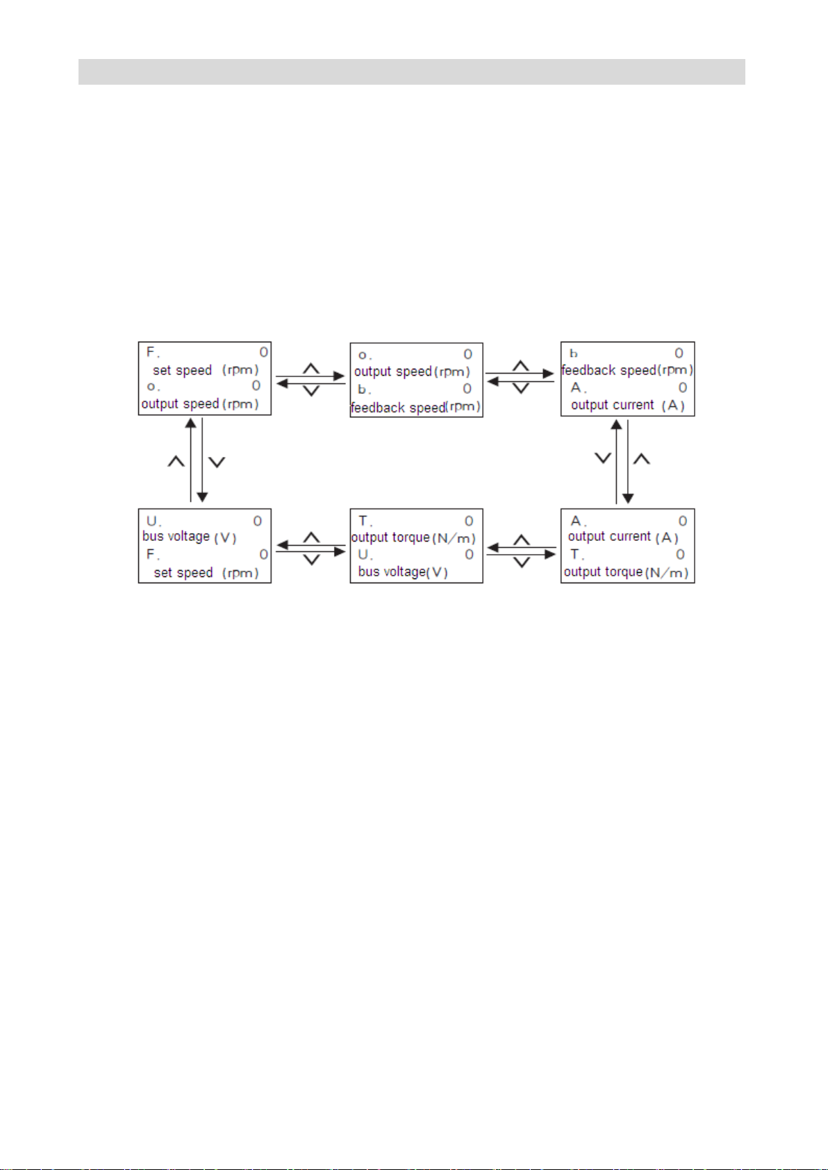
GS DRIVER CTB
★ Description:
10 menu items are included in 1-level menu: U1 menu, U2 menu, U3 menu, A1 menu, A2 menu, A3
menu, C1 menu, D1 menu, E1 menu, P1 menu, T1 menu and L1 menu.
Please see parameter description for detailed function in 2-level menu.
Monitor operating state with the manipulator
Operation state, interface state and fault information of the driver can be monitored respectively through
U1, U2 and U3 of the manipulator
Operation state monitoring
Operation state monitoring includes set speed F, output speed O, feedback speed b, output current A,
output torque T and DC bus voltage U of the driver. Please see Figure 3-21 for monitoring method.
Figure 3-28 Driver operation state monitoring flowchart
Interface state monitoring
Interface state includes driver’s encoder input interfaces U2-00, U2-01; switching value input terminals
U2-02, U2-03; switching value output terminal U2-04, analog input interfaces U2-05, U2-06; output
terminals U2-07, U2-08. The monitoring method is same with monitoring parameter, only needs to select
corresponding parameter in U2. Please see U2 parameter monitoring table 2 for parameter number.
Fault information monitoring
The control panel will display the current fault message code when the driver is in fault state. The fault
record of the driver can be checked through U3. The check operation is same with monitoring parameter,
only needs to select corresponding parameter in U3. Please see fault state recording parameter table U3
for parameter number.
Page 72
CTB GH DRIVER
Test run
The chapter describes methods and precautions for initial test run of the driver
Basic procedure of test run………………………………..4-2
Confirmation of connection of the main circuit………….4-2
Control circuit wiring confirmation………………………..4-3
Motor and driver parameters confirmation ………………4-3
Motor self-learning…… ……………………………………4-3
No-load test run…………………………………………….4-4
Loaded test run……………………………………………..4-4
Page 73
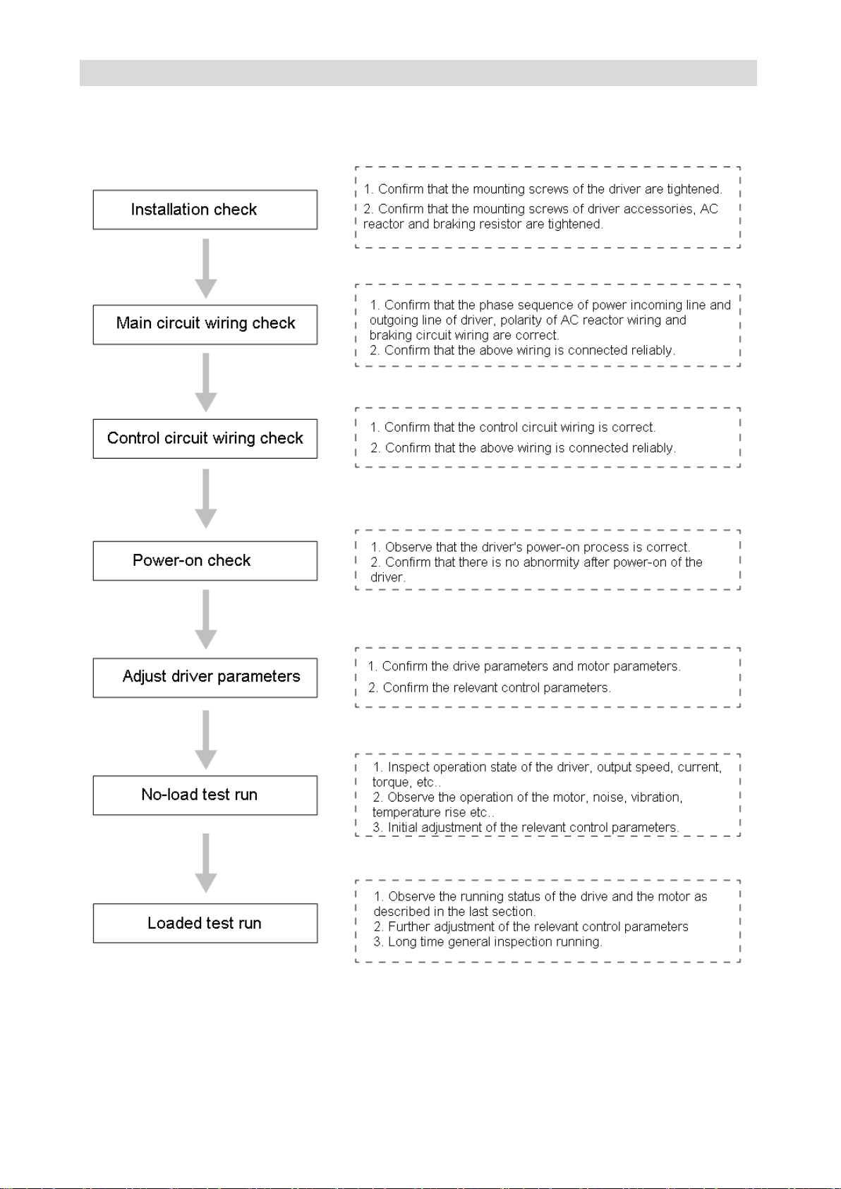
GS DRIVER CTB
Basic procedure of test run
The initial power-on operation of the driver shall be carried out by the following procedures, otherwise,
accident, damage to equipment or other hazards are likely to happen.
Confirmation of the connection of the main circuit
Please confirm the following contents in connection of the main circuit
1. Connect the connecting wire on driver R / S / T to 3-phase power frequency power supply. The
voltage of the power supply shall meet the requirements of the drive.
Page 74
CTB GH DRIVER
Caution
● The wire connection must be inspected carefully before initial power-on of the driver, otherwise, it's
prone to accidents
Caution
If the following situations occur, please shut down immediately and inspect, or contact the manufacturer.
1. Major fluctuation of feedback speed, output current and output torque of the driver, or reach the limit.
2. The motor operation is abnormal with abnormal vibration and noise.
3. Mechanical equipment abnormalities
2. The driver is equipped with built-in braking unit. The braking resistor is connected to P / PB. Do not
connect any connect wire to N terminal.
3. When the output terminal of the driver is connected to the motor, it shall be ensured that their phase
sequences are same, otherwise, he motor cannot operate normally, and prone to burn the equipment. If
shield cable is used for output cable, the shielding layer at the ends of the cable shall be connected
respectively to ground terminal of the drive and motor.
4. When filtering magnet ring is installed on the output line, it shall be close to the driver side as possible.
The shielding layer and ground line cannot pass through the magnet ting, and the magnet ting cannot be
in contact with the U / V / W terminal.
5.The driver and motor must be well grounded.
6. Confirm all connecting wire are connected reliably.
Motor and driver parameters confirmation
The initial parameters of GH series AC servo driver shall be basically in conformity with the practical
application. Most of the parameters do not need modification. For initial application, user shall modify or
confirm part of the parameters as required.
Parameters need to be confirmed in test run
● Motor and driver parameters: D1, D1-00 ~ D1-05.
● Basic control parameters:A2, A2-00~ A2-35.
● Control relevant parameter:A3, A3-00~ A3-69.
Loaded test run
Attention shall be paid to the following contents during loaded test run of the driver:
1. Loading gradually from small to large. Please inspect or contact with the manufacturer for over
loading.
2. Monitor feedback speed, output current and output torque of the driver constantly during loading;
observe motor vibration and noise and temperature rise continuously. The equipment shall be shutdown
timely for any abnormalities.
3. To avoid accident, the motor shall be stopped before adjusting motor parameters. The parameter
regulating quantity shall not be too big.
4. Do not make overload test or destructive test to avoid burning of the driver and motor.
Page 75
GS DRIVER CTB
Parameter list
The chapter describes all of parameters of the driver.
Monitor parameter U1.................................................................................5-2
Monitor parameter U2.................................................................................5-2
Monitor parameter U3.................................................................................5-3
Initialization parameter A1........................................................................5-3
Parameter defined by user A2...................................................................5-4
Parameter defined by user A3...................................................................5-4
User parameter C1.........................................................................5-4
Motor driving parameter D1........................................................................5-6
Encoder parameter E1........................................................................5-7
Protection parameter P1........................................................................5-8
Communication pameter T1.....................................................................5-9
Manufacturer parameter L1........................................................................5-9
Page 76
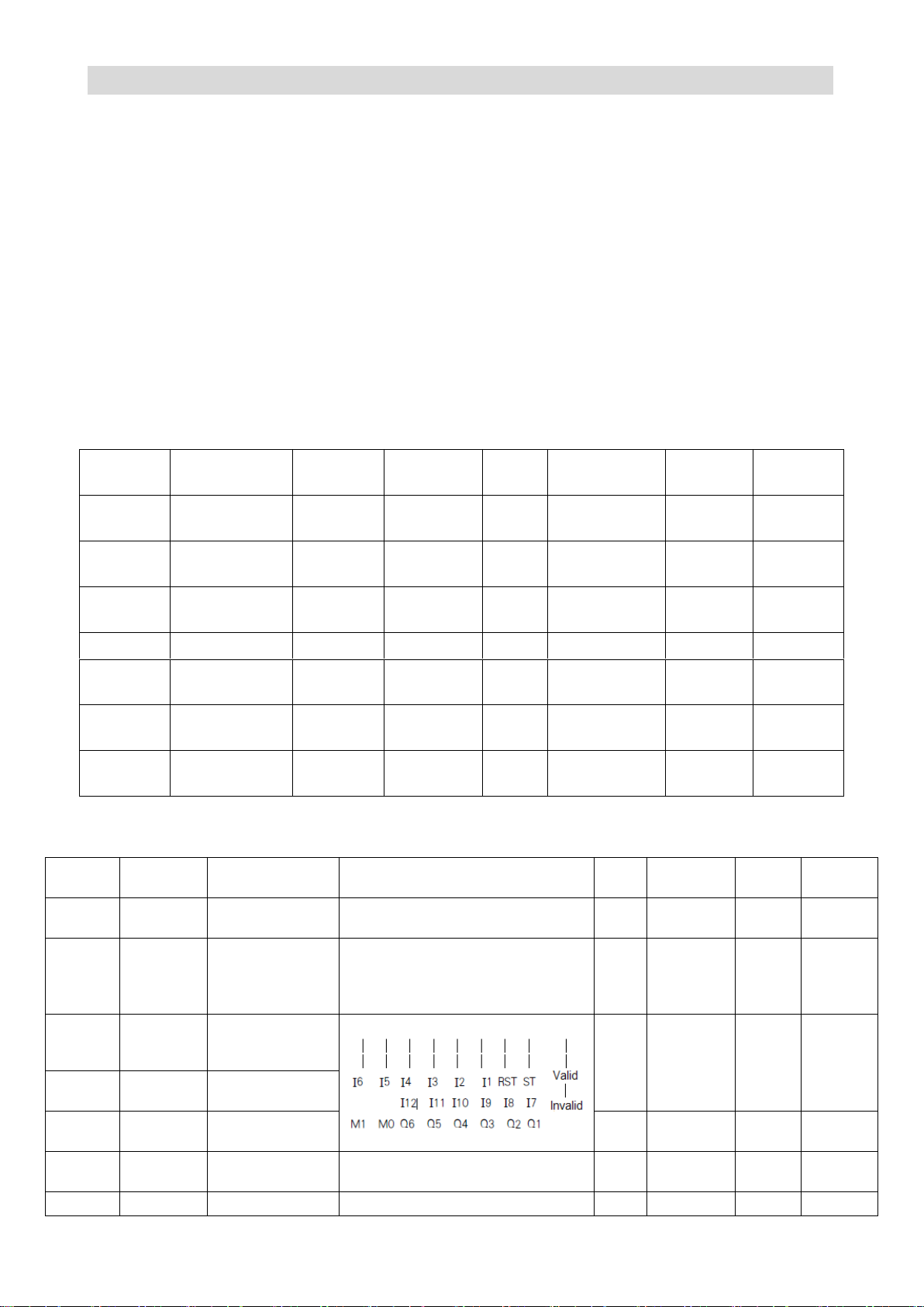
CTB GH DRIVER
Function code:
Code of parameter group and parameter number;
Name:
Name of the parameter;
Description:
Detailed description about function and effective setting value of the parameter;
Setting range:
The range of effective setting value of parameter;
Unit:
Parameter setting unit;
Factory setting:
Original factory parameter setting;
Change:
Parameter changing properties (ie, allow changing or not and change condition) are
as follows:
Function
code
PLC address
Name
Description
Unit
Parameter
scope
original
value
Property
U1-0
D6291+D6292
Speed
setting
Speed
setting
rpm
0 to 20000
0
On line
U1-1
D6293+D6294
Speed
output
Speed
output
rpm
0 to 20000
0
Read only
U1-2
D6303+D6304
Speed
feedback
Speed
feedback
rpm
0 to 20000
0
Read only
U1-3
D6302
Current
Current
A
0 to 2000
0
Read only
U1-4
D6301
Torque
current
Torque
current
A
0 to 2000
0
Read only
U1-5
D6319
Bus
voltage
Bus
voltage
V
0 to 1000
0
Read only
U1-6
D6320
following
error
following
error
pulse
0 to 10000
0
Read only
Function
code
PLC
address
Name
Description
Unit
Parameter
scope
original
value
Property
U2-0
D6311
First coded disc
counting
First coded disc counting
accumulation
Pulse
0 to 65535
0
Read
only
U2-1
D6313
Second coded
disc counting
Second coded disc counting
accumulation
T2 pulse port pulse accumulation
counting
Pulse
0 to 32768
0
Read
only
U2-2
D6445
State of input
points I1-I6, ST,
RST
- - 0
Read
only
U2-3
D6446
State of input
points I7 to I12
U2-4
D6447
state of M0, M1,
Q0 to Q6
- - 0
Read
only
U2-5
D6448
FI after filtering
AD value of unipolar analog quantity of
the first circuit
-
0 to 4095
0
Read
only
U2-6
D6449
FV after filtering
AD value of bipolar analog quantity
-
0 to 4095
0
Read
Parameter list description
The contents of the parameter list are described as follows:
Monitoring parameter U1
Monitoring parameter U2
Page 77
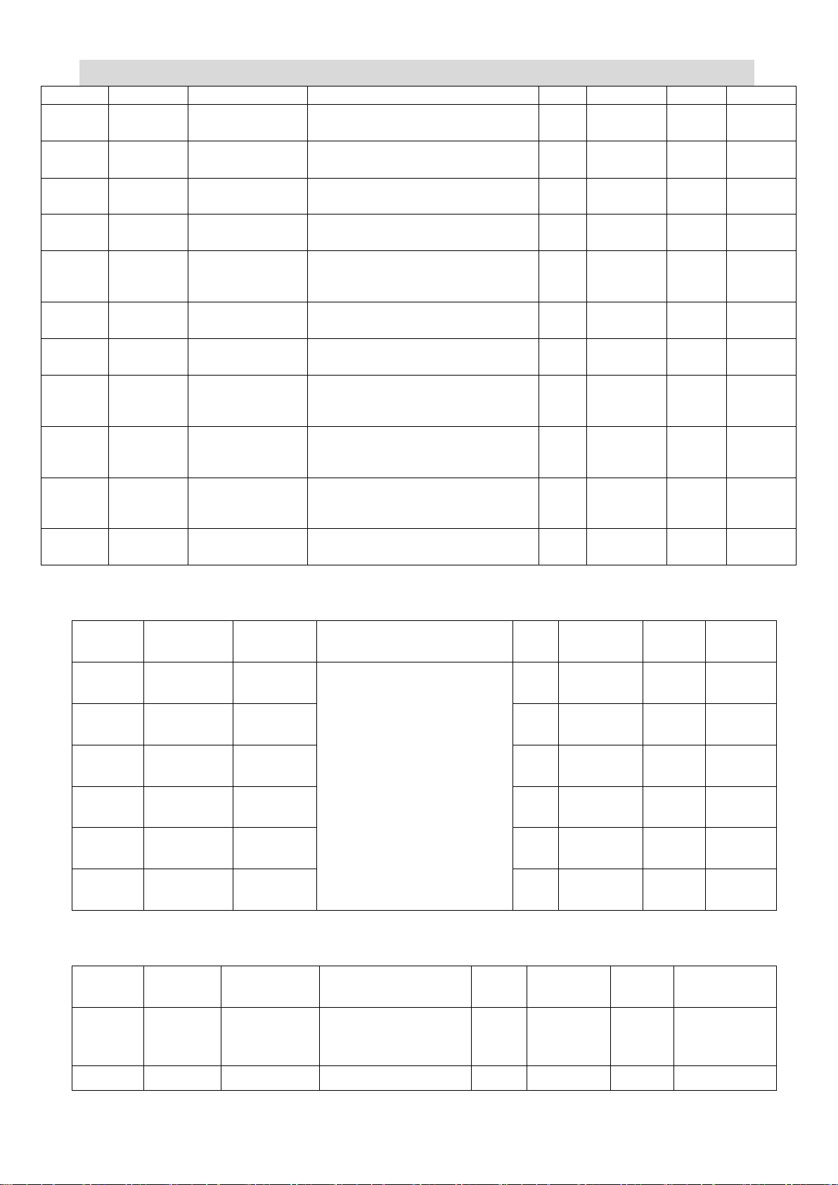
GS DRIVER CTB
only
U2-7
D6454
DA1
DA1 output digital quantity
-
0 to 4095
0
Read
only
U2-8
D6455
DA2
DA2 output digital quantity
-
0 to 4095
0
Read
only
U2-9
D6456
Temperature of
driver module
Temperature of driver module
-
0 to 100
0
Read
only
U2-10
D6457
Temperature of
CPU
Temperature of CPU
-
0 to 100
0
Read
only
U2-11
D6325
Pulse number of
the first coded
disc distance Z
Pulse number of single circle position
distance
Pulse
0 to 60000
0
Read
only
U2-12
D6315
Pulse 1 counting
Pulse 1 counting
Pulse
0 to 60000
0
Read
only
U2-13
D6317
Pulse 2 counting
Pulse 2 counting
Pulse
0 to 60000
0
Read
only
U2-14
D6332
Angle of the
second coded disc
distance Z
Pulse number of single circle position
distance Z
0.01
degre
e
0 to 36000
0
Read
only
U2-15
D6333-D5
334
Pulse of the first
coded disc
distance Z
Pulse 1 counting
Pulse
32bit
0
Read
only
U2-16
D6335-D5
336
Pulse of the
second coded disc
distance Z
Pulse 2 counting
Pulse
32bit
0
Read
only
U2-17
D6337
Temperature of
the motor
Display of temperature of the motor
℃
25-150
0
Read
only
Function
code
PLC
address
Name
Description
Unit
Parameter
scope
original
value
Property
U3-0
D6420
Current
fault code
See fault description for
detail
- - -
Read
only
U3-1
D6421
last 1st
fault code
- - -
Read
only
U3-2
D6422
last 2nd
fault code
- - -
Read
only
U3-3
D6423
last 3rd
fault code
- - -
Read
only
U3-4
D6424
last 4th
fault code
- - -
Read
only
U3-5
D6425
last 5th
fault code
- - -
Read
only
Function
code
PLC
address
Name
Description
Unit
Parameter
scope
original
value
Property
A1-00
D6000
Password
protection
Start parameters
after group C when it
is set as 1
-
0-1
0
On line
A1-01
D6001
Base power
Base power
KW
0-1000
0
Read only
Monitoring parameter U3
Initialization parameter A1
Page 78
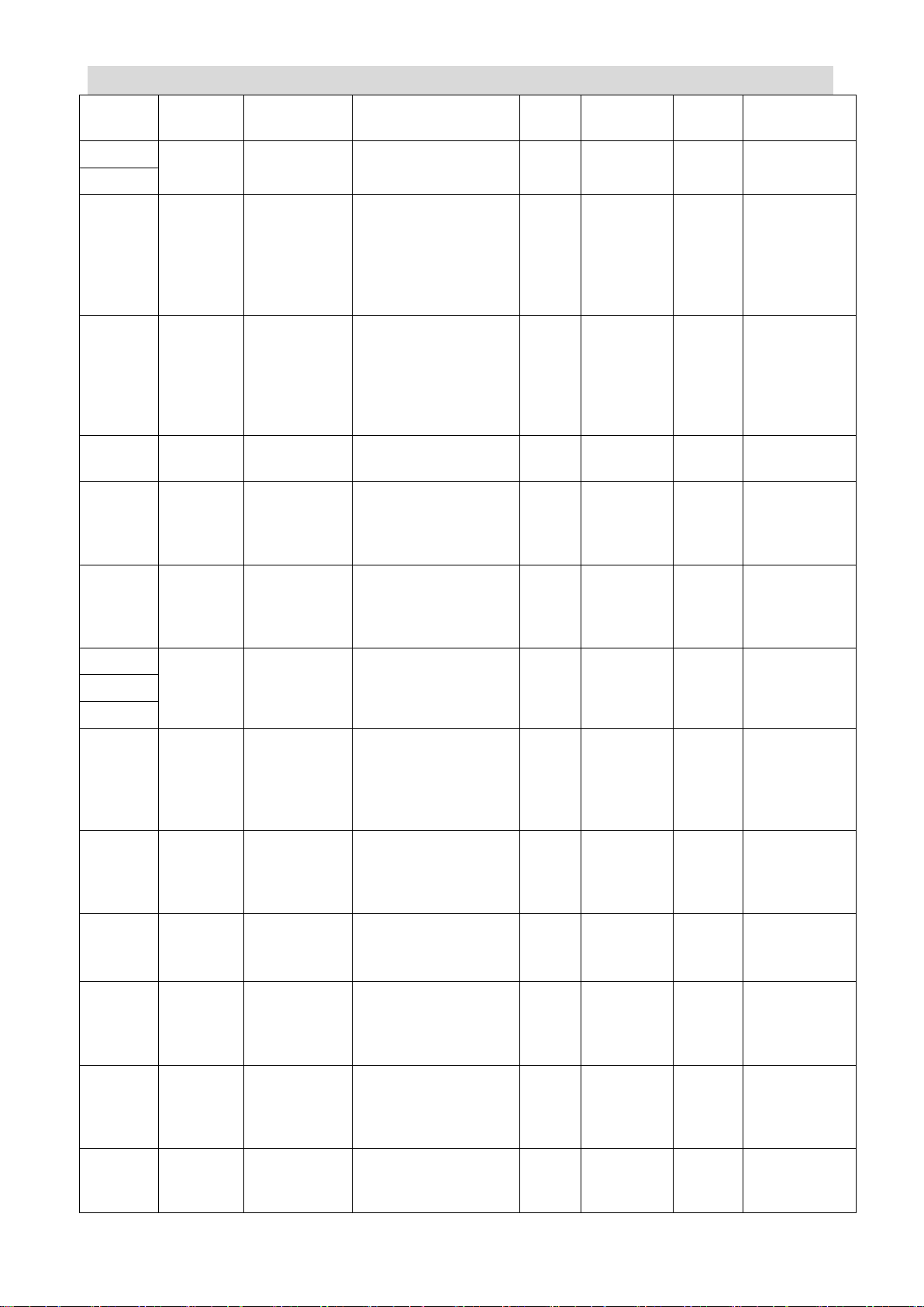
CTB GH DRIVER
A1-02
D6002
Power code
Power code read
from base
- - 0
Read only
A1-03
-
Save
-
- - -
-
A1-04
A1-05
D6005
Clear user’s
parameters
for next
power-on
Restore default
setting of
parameters for next
power-on non-0
restore default
setting
-
0-10000
0
Power on
again
A1-06
D6006
Restore
default
setting of
parameters
for next
power-on
Restore default
setting of
parameters for next
power-on non-0
restore default
setting
-
0-10000
0
Power on
again
A1-07
D6007
PLC version
number
PLC version number
-
0-30000
0
Read only
A1-08
D6008
Control
program
version
number
Control program
software version
number
-
0-30000
0
Read only
A1-09
D6009
Application
program
version
number
Application program
software version
number
-
0-30000
0
Read only
A1-10
-
Save
--
- - -
-
A1-11
A1-12
A1-13
D6013
Minimum
calibration
value limit
Calibration is invalid
when the analog
quantity calibration
speed is lower than
the value
-
0-10000
0
On line
A1-14
D6014
Calibration
error scope
Allowed error scope
percent of the
analog quantity
calibration
0-10
0
On line
A1-15
D6015
Auto/manual
0: automatic
calibration
1: manual calibration
-
0-1
0
On line
A1-16
D6016
Calibration
positive bias
Set manual
calibration positive
bias of analog
quantity
LSB
0-65520
0
On line
A1-17
D6017
Calibration
negtive bias
Set manual
calibration negtive
bias of analog
quantity
LSB
0-65520
0
On line
A1-18
D6018
FI analog
quantity
sampling
FV analog quantity
input voltage value
monitoring
0.1V
0-10
0
Read only
Page 79
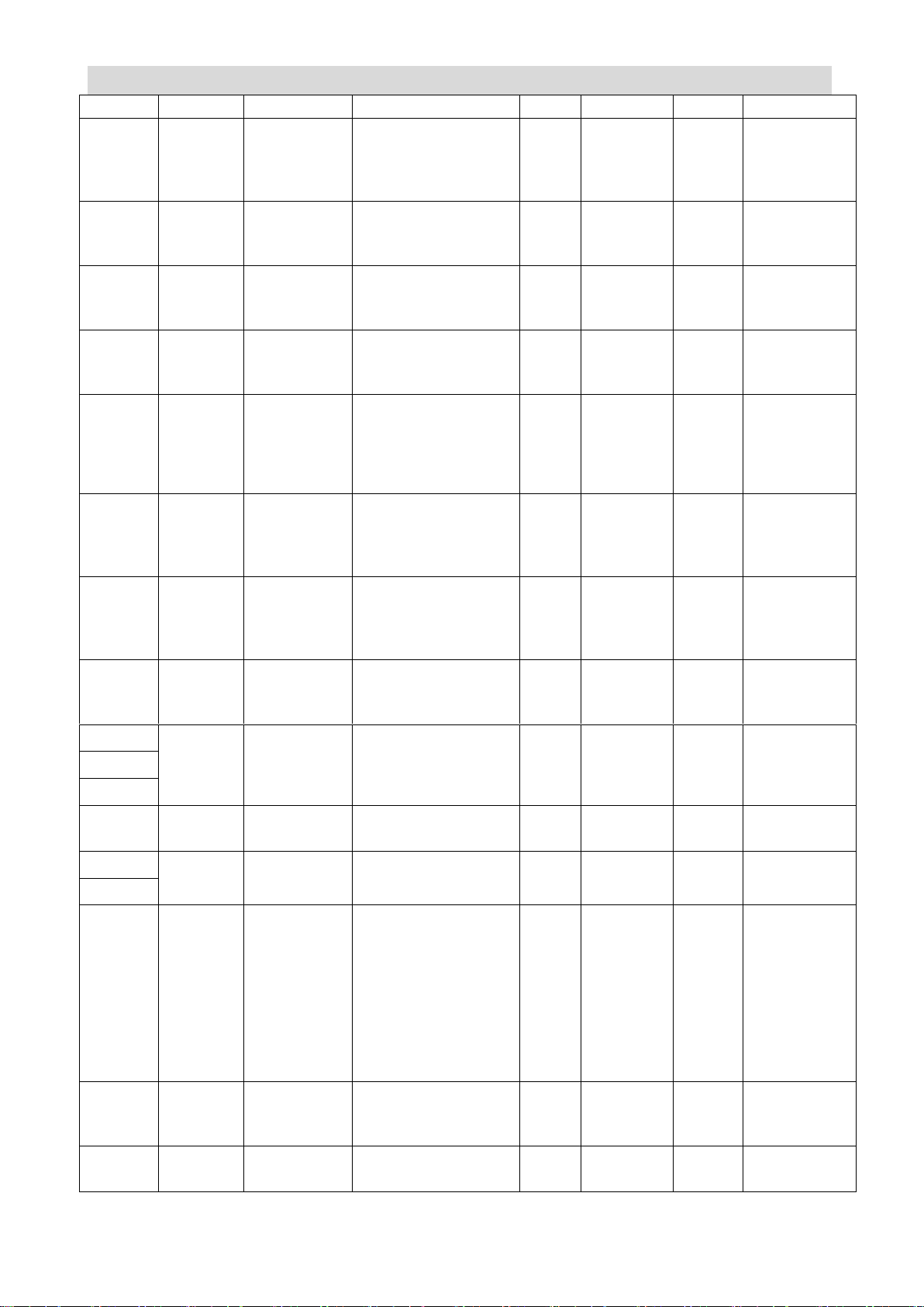
GS DRIVER CTB
value
A1-19
D6019
FV analog
quantity
sampling
value
FV analog quantity
input voltage value
monitoring
0.1V
-20
0
Read only
A1-20
D6020
FV
calibration
order
Set FV analog
quantity calibration
speed
rmp
0-65535
0
On line
A1-21
D6021
FI
calibration
order
Set FI analog
quantity calibration
speed
rmp
0-65535
0
On line
A1-22
D6022
FT
calibration
order
Set FT analog
quantity calibration
speed
rmp
0-65535
0
On line
A1-23
D6023
Analog
quantity
channel
selection
0: no selection
1: FV
2: FI
3:FV FI FT
-
0-3
0
On line
A1-24
D6024
Analog
quantity
filtering
times
Set analog quantity
filtering times
Times
0-4000
2000
On line
A1-25
D6025
Analog zero
speed
deadzone
It is considered as 0
speed when the
analog quantity is
less than the value
LSB
0-65520
0
On line
A1-26
D6026
Analog
maximum
speed
The analog quantity
corresponding to the
maximum speed
rmp
0-30000
1000
On line
A1-27
-
Save
-
- - -
-
A1-28
A1-29
A1-30
D6030
Input
filtering time
Calculation method:
A1-30*0.5ms
0.5ms
0-30000
0
On line
A1-31
Save
-
- - -
-
A1-32
A1-33
D6033
The middle
value
function of
the analog
quantity
under initial
calibration is
started or
not ?
0: do not start
1: start
-
0-1
1
On line
A1-34
D6034
Time of
section A of
curve S
set time of section A
of curve S
ms
0-2000
10
On line
A1-35
D6035
Time of
section B of
set time of section B
of curve S
ms
0-2000
10
On line
Page 80
CTB GH DRIVER
curve S
A1-36
D6036
Time of
section C of
curve S
set time of section C
of curve S
ms
0-2000
10
On line
A1-37
D6037
Time of
section D of
curve S
set time of section D
of curve S
ms
0-2000
10
On line
A1-38
D6038
PLC control
Q6 enabling
Q6 is controlled by
free programming of
PLC when this value
is 1, instead of z
output
-
0-1
0
On line
A1-39
D6039
Port com1
function
selection
0: PLC
communication
1: upper computer
communication
-
0-1
0
Non-enabling
Function
code
PLC
address
Name
Description
Unit
Parameter
scope
original
value
Property
A2-01
D1201
Analog
quantity
polarity
selection
0:±10V
1:0-10V
-
0-1
0
Non-enabling
A2-02
-
Save
-
- - -
-
A2-03
D1203
Positioning
mode
0:motor encoder
positioning
1:spindle encoder
positioning
2:approach switch
positioning
-
0-2
-
Non-enabling
A2-04
-
Save
-
- - -
-
-
A2-11
A2-12
D1212
ST
function
selection
0:no function
1:communication
control enabling
-
0-1
0
Non-enabling
A2-13
D1213
Positioning
mode
0:positioning
according to current
speed direction
1: positioning
according to fixed
direction
-
0-1
0
Non-enabling
A2-14
D1214
Positioning
direction
selection
0:positive positioning
1: negative
positioning
-
0-1
0
Non-enabling
A2-15
D1215
I1 function
selection
0:analog quantity
speed
1: pulse speed
0-1
-
Non-enabling
User self-defined parameter A2
Page 81
GS DRIVER CTB
A2-16
-
Save
-
- - -
-
A2-17
D1217
Pulse port
selection
0:T4 input 5V
differential pulse
1:T2 input 5V
differential pulse
2: T3 input 24V pulse
-
0-2
-
Non-enabling
A2-18
D1218
Feedback
source at
pulse
position
0:motor encoder
1:spindle encoder
-
0-1
0
Non-enabling
A2-19
D1219
I4 function
selection
0:analog quantity rigid
tapping
1: pulse rigid tapping
-
0-1
-
Non-enabling
A2-20
-
Save
-
- - -
-
-
A2-99
Function
code
PLC
address
Name
Description
Unit
Parameter
scope
original
value
Property
A3-00
-
Save
-
- - -
-
-
A3-07
A3-08
D1308
Withdraw I0
port 0 speed
spindle locking
time
Set Withdraw I0
port 0 speed
spindle locking
time
ms
0-30000
300
Non-enabling
A3-09
D1309
Withdraw I0
port
deceleration
time
Set Withdraw I0
port deceleration
time
0.01s
0-30000
-
Non-enabling
A3-10
-
Save
-
- - -
-
A3-11
A3-12
D1312
Speed setting
during
MODBUS
communication
control
Set speed setting
during MODBUS
communication
control
rmp
±30000
0
Non-enabling
A3-13
-
Save
-
- - -
-
-
A3-18
A3-19
D1319
Corresponding
speed when
analog voltage
DA1 outputs
10V
Set corresponding
speed when
analog voltage
DA1 outputs 10V
rmp
±65535
-
Non-enabling
User self-defined parameter A3
Page 82
CTB GH DRIVER
A3-20 - Save
-
- - -
-
A3-21
D1321
Corresponding
speed when
analog voltage
DA2 outputs
10V
Set corresponding
speed when
analog voltage
DA2 outputs 10V
0.1A
±65535
-
Non-enabling
A3-22 - Save
-
- - -
-
A3-23
D1323
Corresponding
maximum
speed of
speed control
of 10V
Input
corresponding
speed when 10V
analog voltage is
input
rmp
0-20000
-
Non-enabling
A3-24
D1324
speed control
acceleration
time
Set speed control
acceleration time
0.01s
0-20000
100
Non-enabling
A3-25
D1325
speed control
deceleration
time
Set speed control
deceleration time
0.01s
0-20000
100
Non-enabling
A3-26 - Save
-
- - -
-
A3-27
D1327
Speed control
scale gain
Set speed loop
regulator scale
gain. The gain is
higher and the
rigidity is bigger
with greater value.
Set the value as
high as possible
without vibration in
the system
-
0-30000
-
Non-enabling
A3-28
D1328
Speed control
integral time
Set speed ring PI
regulator integral
time. The rigidity is
higher with lower
value
-
Non-enabling
A3-29 - save
-
- - -
-
A3-30
D1330
Rigid tapping/
pulse position
maximum
speed time
Set the maximum
speed of motor
during Rigid
tapping/ pulse
position control
rmp
0-20000
1500
Non-enabling
A3-31
D1331
Rigid tapping/
pulse position
acceleration
time
Set Rigid tapping/
pulse position
acceleration time
0.01s
0-20000
100
Non-enabling
A3-32
D1332
Rigid tapping/
pulse position
deceleration
time
Set Rigid tapping/
pulse position
deceleration time
0.01s
0-20000
100
Non-enabling
A3-33
D1333
Position loop
feed-forward at
Rigid tapping/
The position ring
response is faster
when the value is
-
0-100
-
Non-enabling
Page 83
GS DRIVER CTB
pulse position
greater
A3-34
D1334
Position loop
scale gain at
Rigid tapping/
pulse position
The position ring
rigidity is higher
when the value is
greater
-
0-30000
-
Non-enabling
A3-35
D1335
speed loop
scale gain at
Rigid tapping/
pulse position
Set speed loop
scale gain at
Rigid tapping/
pulse position. The
gain is higher and
the rigidity is bigger
with greater value.
Set the value as
high as possible
without vibration in
the system
-
0-30000
-
Non-enabling
A3-36
D1336
speed loop
integral time at
Rigid tapping/
pulse position
Set speed loop
integral time at
Rigid tapping/
pulse position. The
rigidity is higher
with lower value
-
0-30000
-
Non-enabling
A3-37 - save
-
- - -
-
A3-38
D1338
First
positioning
bais
Set First
positioning bais
Pulse
0-65535
0
Non-enabling
A3-39 - save
-
- - -
-
A3-40
D1340
Positioning
speed
Look for encoder
phase Z pulse or
speed of the
approach switch
rmp
0-20000
100
Non-enabling
A3-41
D1341
Positioning
position ring
acceleration
tmie
Set Positioning
position ring
acceleration tmie
0.01s
0-20000
100
Non-enabling
A3-42
D1342
Positioning
acceleration
tmie
Set Positioning
acceleration tmie
0.01s
0-20000
100
Non-enabling
A3-43
D1343
Positioning
deceleration
tmie
Set Positioning
deceleration tmie
0.01s
0-20000
100
Non-enabling
A3-44
D1344
Positioning
position ring
scale gain
Set positioning
position ring scale
gain. the response
to the position
order gain is faster
and the rigidity is
higher with higher
set value. A too
high value may
cause position
overshoot when
-
0-30000
-
Non-enabling
Page 84
CTB GH DRIVER
start stops. The
effect is slower and
the error increases
with lower value.
A3-45
D1345
Positioning
speed ring
scale gain
Set positioning
speed ring PI
regulator scale
gain. the gain is
greater and the
rigidity is higher
with higher set
value
-
0-30000
-
Non-enabling
A3-46
D1346
Positioning
speed ring
integeral time
Set positioning
speed ring PI
regulator integral
time. the
integrating speed
is greater and the
rigidity is higher
with smaller set
value
-
0-30000
-
Non-enabling
A3-47
D1347
Second
positioning
bias
Set second
positioning bias
Pulse
0-65535
1000
Non-enabling
A3-48
-
save
-
- - -
-
-
A3-62
A3-63
D1363
Inching
forward speed
Set Inching forward
speed
Rmp
0-20000
200
Non-enabling
A3-64
D1364
Inching
reverse speed
Set Inching reverse
speed
Rmp
0-20000
200
Non-enabling
A3-65
D1365
Inching
acceleration
time
Set Inching
acceleration time
0.01s
0-20000
100
Non-enabling
A3-66
D1366
Inching
deceleration
time
Set Inching
deceleration time
0.01s
0-20000
100
Non-enabling
A3-67
-
Save
-
- - -
-
-
A3-99
Function
code
PLC
address
Name
Description
Unit
Paramete
r scope
original
value
Property
C1-00
D6040
speed
reverse order
0: do not reverse
1: reverse
-
0~1
0
on line
C1-01
D6041
speed ring
acceleration
speed ring
acceleration
0.01s/Krp
m
0~20000
100
on line
C1-02
D6042
speed ring
speed ring
0.01s/Krp
0~20000
100
on line
User parameters C1
Page 85

GS DRIVER CTB
deceleration
deceleration
m
C1-03
D6043
position
operation
feedback
source
0: first code wheel
(T5)
1: second code
wheel (T4)
2: first pulse port
(T2)
3: second pulse
port (T3-24V)
-
0~3
0
non-enab
ling
C1-04
D6044
position
operation
order source
0: invalid
1: first code wheel
(T5)
2: second code
wheel (T4)
3: first pulse port
(T2)
4: second pulse
port (T3-24V)
5: interior order
-
0~5
0
non-enab
ling
C1-05
D6045
pulse speed
order source
2:T4
3:T2
4:T3
other :invalid
-
0-5
0
non-enab
ling
C1-06
D6046
positioning
speed
positioning
execute process
maximum limit
speed
rpm
0~30000
100
on line
C1-07
D6047
T-type
positioning
acceleration
0.01s/Krp
m
0~30000
100
on line
C1-08
D6048
positioning
direction
0: forward 1:
reverse
-
0~1
0
on line
C1-09
D6049
first
positioning
gain
first gain during
positioning, the
gain is greater
-
0~30000
2
on line
C1-10
D6050
second
positioning
gain
second gain
during
positioning , the
gain is smaller
-
0~30000
1
on line
C1-11
D6051
positioning
gain switch
speed
threshold
positioning first
gain and second
gain switch
threshold , when
the residue
distance is smaller
than the value,
switch to second
gain , otherwise,
use first gain
-
0~30000
100
on line
C1-12
D6052
positioning
minimum
speed
positioning crawlin
end minimum
speed
rpm
0~30000
1
on line
Page 86
CTB GH DRIVER
C1-13
D6053
third section
positioning
distance
threshold
third section
positioning
distance
threshold , when
the residue
distance is smaller
than the
parameter,
conduct third
section positioning
operation
0.01R
0-30000
0.01
on line
C1-14
D6054
positioning
reach scope
When positioning
residue distance
is smaller than the
value, it is
determined that
the positioning is
reached, and
output positioning
reach signal
pulse
0~30000
2
on line
C1-15 - save
-
- - -
-
C1-16
D6056
precise
positioning
scope
When positioning
residue distance
is smaller than the
value, it is
determined that
the precise
positioning is
reached, and
output precise
positioning reach
signal
pulse
0~30000
1
on line
C1-17
D6057
swing forward
scope
swing forward
position
pulse
0~30000
100
on line
C1-18
D6058
swing reverse
scope
swing reverse
position
pulse
0~30000
100
on line
C1-19
D6059
swing speed
upper limit
maximum speed
during swing
rpm
0~6000
50
on line
C1-20
D6060
swing
acceleration
acceleration
during swing
s/krpm
0~30000
1
on line
C1-21
D6061
swing
deceleration
deceleration
during swing
s/krpm
0~30000
1
on line
C1-22
D6062
swing current
swing current
A
0~30000
0.5
on line
C1-23
D6063
phase to z
phase
positioning
zero point
source
0: select
according to
position order
source
1: exterior I/O is
taken as z phase
signal
-
0, 1
0
non-enab
ling
C1-24
D6064
z phase
positioning
positive and
negative
Solve inconsistent
issue of z phase
large pulse width
positive and
-
0-65535
0
enabling
Page 87
GS DRIVER CTB
compensation
negative
positioning
position
C1-25
D6065
positioning
maximum
deceleration
Take the
deceleration as
lower limit of
deceleration after
entering
positioning
module
-
0-20000
0.5
enabling
C1-26 - save
-
- - -
-
~
C1-28
C1-29
D6069
order mode
select
0: terminal
operation mode
1: panel operation
mode
2: mechatrolink
bus order control
3: ethercat bus
-
0~3
0
non-enab
ling
C1-30
D6070
control mode
0: speed control
1: position control
2: torque control
-
0~2
0
on line
C1-31
D6071
current ring
KP
current ring
scale parameter
(KP)
-
0~30000
100
on line
C1-32
D6072
current ring
TI
current ring
integral time
constant (TI)
-
0~30000
8
on line
C1-33
D6073
speed ring KP
speed ring scale
parameter (KP)
-
0~30000
140
on line
C1-34
D6074
speed ring TI
speed ring integral
time constant (TI)
-
0~30000
15
on line
C1-35
D6075
speed ring
second set
parameter
valid
threshold
second set PI
parameter valid
speed threshold ,
when the given
speed is smaller
than the maximum
speed times the
value percent, use
second set
parameter
-
0~1000
0
on line
C1-36
D6076
speed ring
second KP
second speed
gain (KP2)
-
0~30000
140
on line
C1-37
D6077
speed ring
second TI
second speed
integral time
constant (TI2)
-
0~30000
15
on line
C1-38
D6078
position ring
KP
second speed
gain (KP2)
-
0~30000
300
on line
C1-39
D6079
position ring
position ring
-
0~100
100
on line
Page 88

CTB GH DRIVER
feedforward
speed
feedforward (kW)
C1-40
D6080
d shaft
current ring
KP
current ring scale
parameter (Kp)
-
0-30000
100
on line
C1-41
D6081
d shaft
current ring
TI
current ring
integral time
constant (Ti)
-
0-30000
800
on line
C1-42
D6082
voltage ring
KP
voltage ring scale
parameter (Kp)
-
0-30000
400
on line
C1-43
D6083
voltage ring
TI
voltage ring
integral time
constant (Ti)
-
0-30000
40
on line
Function
code
PLC
address
Name
Description
Unit
Paramet
er scope
original
value
Property
Recommend
motor
D1-00
D6090
rated current
motor rated
current
A
0~
60000
1100
non-enabli
ng
synchronous /
asynchronous
D1-01
D6091
rated speed
motor rated
speed
rpm
0~
30000
1500
non-enabli
ng
synchronous /
asynchronous
D1-02
D6092
rated voltage
motor rated
voltage
V
0~3000
380
non-enabli
ng
synchronous /
asynchronous
D1-03
D6093
rated power
motor rated
power
KW
0~
30000
55
non-enabli
ng
synchronous /
asynchronous
D1-04
D6094
power factor
motor power
factor angle
-
0~100
83
non-enabli
ng
asynchronous
D1-05
D6095
rated
frequency
motor rated
frequency
HZ
0~
30000
50
non-enabli
ng
asynchronous
D1-06
D6096
stator
resistance
the
parameter is
save
parameter ,
shall not be
used
-
0-30000
0
non-operati
onal
asynchronous
D1-07
D6097
Sigma
inductor
the
parameter is
save
parameter ,
shall not be
used
-
0-30000
0
non-operati
onal
asynchronous
D1-08
D6098
rotor
resistance
the
parameter is
save
parameter ,
shall not be
used
-
0-30000
0
non-operati
onal
asynchronous
D1-09
D6099
number of
pole-pairs
motor
number of
pole-pairs
pairs
0~
30000
2
non-enabli
ng
synchronous
/asynchronous
D1-10
D6100
magnetic
head
inductor
the
parameter is
save
parameter ,
shall not be
used
-
0-30000
0
non-operati
onal
asynchronous
Motor driving parameter D1
Page 89

GS DRIVER CTB
D1-11
D6101
motor protect
mode
the
parameter is
save
parameter ,
shall not be
used
-
0-30000
0
non-operati
onal
asynchronous
D1-12
D6102
motor protect
rated current
motor protect
point current
A
0~
60000
1100
non-enabli
ng
synchronous
/asynchronous
D1-13
D6103
magnetizatio
n current
the
parameter is
save
parameter ,
shall not be
used
-
0-30000
0
non-operati
onal
asynchronous
D1-14
D6104
rated torque
motor rated
torque
nm
0~
30000
35
non-enabli
ng
synchronous
/asynchronous
D1-15
D6105
FU
maximum
torque
the
parameter is
save
parameter ,
shall not be
used
-
0-30000
0
non-operati
onal
asynchronous
D1-16
D6106
maximum
torque
angular
speed
the
parameter is
save
parameter ,
shall not be
used
-
0-30000
0
non-operati
onal
asynchronous
D1-17
D6107
maximum
torque speed
the
parameter is
save
parameter ,
shall not be
used
-
0-30000
0
non-operati
onal
asynchronous
D1-18
D6108
weak field
area speed
the
parameter is
save
parameter ,
shall not be
used
-
0-30000
0
non-operati
onal
asynchronous
D1-19
D6109
magnetic flux
adaptation
factor
the
parameter is
save
parameter ,
shall not be
used
-
0-30000
0
non-operati
onal
asynchronous
D1-20
D6110
weak field
area current
curve
Qd current
maximum
scale
-
0~
30000
10
non-enabli
ng
asynchronous
D1-21
D6111
rotating-spee
d difference
compensatio
n multiplying
power
coefficient
rotating-spee
d difference
compensatio
n multiplying
power
coefficient,
multiply by
256
-
0~
30000
224
non-enabli
ng
asynchronous
D1-22
D6112
rotor time
constant
rotor time
constant
-
0~
30000
50
non-enabli
ng
asynchronous
D1-23
D6113
rotating-spee
d difference
maximum
compensatio
n
rotating-spee
d difference
compensatio
n upper limit
-
0~
30000
65
non-enabli
ng
asynchronous
Page 90
CTB GH DRIVER
D1-24
D6114
synchronous
motor
counter
potential per
1000 turns
synchronous
motor
no-load
counter
potential per
1000 turns
V
0~
30000
110
non-enabli
ng
synchronous
D1-25
D6115
Allowed
output
maximum
speed
Allowed
output
maximum
speed
rpm
0~
30000
6000
non-enabli
ng
synchronous
/asynchronous
D1-26
D6116
Allowed
output
maximum
current
Allowed
output
maximum
torque
current
A
0~
60000
1100
on line
synchronous
/asynchronous
D1-27
D6117
Constant
power zone
maximum
speed
Interface
speed
between
Constant
power zone
and falling
power zone
rpm
0~
30000
3000
non-enabli
ng
asynchronous
D1-28
D6118
pre-excitatio
n time
motor
pre-excitatio
n time
ms
0~
30000
300
non-enabli
ng
asynchronous
D1-29
D6119
minimum
excitation
current
excitation
current
lower limt
0.01A
0~
30000
100
non-enabli
ng
D1-30
D6120
motor type
select
0:
synchronous
motor
1:
asynchronou
smotor
-
0, 1
1
non-enabli
ng
synchronous
/asynchronous
D1-31
D6121
brake torque
limit
brake torque
current
limit
-
0-60000
100
non-enabli
ng
synchronous
/asynchronous
D1-32
D6122
PMflux-weak
ening curve
Suitable for k
curve slope
during
flux-weakeni
ng of
embeddedpe
rmanent ma
gnet
motor
flux-weakeni
ng
-
0-10000
100
non-enabli
ng
synchronous
D1-33
D6123
PM
flux-weakeni
ng direction
Suitable
fordirection
control
during
flux-weakeni
ng of
embeddedpe
rmanent ma
gnet
motor
-
0-1
0
non-enabli
ng
synchronous
D1-34
-
save
- - - - -
-
~
D1-37
D1-38
D6128
brake torque
limit enabling
0: do not use
brake torque
single
parameter
-
0-1
0
non-enabli
ng
synchronous
/asynchronous
Page 91
GS DRIVER CTB
1: use smart
torque single
parameter
D1-39
D6129
carrier wave
cycle
0: 8k
1: 4k
2: 2k
-
0~2
0
power on
again
synchronous
/asynchronous
Function
code
PLC
address
Name
Description
Unit
Parameter
scope
Original
value
Property
E1-00
D6130
Motor encoder
type (T5)
0: TTL
1: resolver
2: Tamagawa multiple
turns encoder
3: bissprotocol
4: only increment
encoderof ABZ is used for
synchronous motor
-
0~4
0
Power on
again
E1-01
D6131
Motor
optoelectronic
code wheel
line number
(T5)
Motor TTL encoder line
number
Pulse
0~10000
2500
Power on
again
E1-02
D6132
Encoder
counting
direction (T5)
0: anticlockwise adding
counting
1: anticlockwise minus
counting
-
0~1
0
On line
E1-03
D6133
Encoder
reduction ratio
numerator
(T5)
一 code wheel reduction
ratio numerator
-
0~30000
1
Non-enabling
E1-04
D6134
Encoder
reduction ratio
denominator
(T5)
一 code wheel reduction
ratio denominator
-
0~30000
1
Non-enabling
E1-05
D6135
Speed
feedback
filtering times
(T5)
Speed feedback filtering
times
-
0~256
60
Non-enabling
E1-06
D6136
Encoder angle
forward offset
value (T5)
Angle forward offset
Pulse
0~30000
0
Non-enabling
E1-07
D6137
Encoder angle
reverse offset
value (T5)
Angle reverse offset
Pulse
0~30000
0
Non-enabling
E1-08
D6138
Motor
absolute value
encoder
single round
bits / resolver
single round
bits (T5)
Motor absolute value
encoder /resolver single
round bits
-
0~32
17
Power on
again
E1-09
D6139
Motor
absolute value
encoder
multiple turns
bits (T5)
Multiple turns absolute
value encoder multiple
turns bits
-
0~32
16
Power on
again
E1-10
D6140
Resolver
/absolute
value
encoder initial
angle record
lower 16 bits
(T5)
Motor resolver initial
phase angle lower 16 bits
-
0~65535
0
Read only
Encoder parameter E1
Page 92

CTB GH DRIVER
E1-11
D6141
Resolver
/absolute
value
encoder initial
angle record
higher 16
bits (T5)
Motor resolver initial
phase angle higher 16
bits
-
0~65535
0
Read only
E1-12
D6142
Driver
encoder
self-learning
order (T5)
If the Feed shaft has
absolute value encoder ,
self-learning initial angle
function , modify it to
123, and may start
self-learning
-
0~200
0
Non-enabling
E1-13
D6143
Encoder
self-learning
time
Set self-learning time , the
learing effect is better for
longer learing time, and
minimum time is 1s
S
0-20
5
Non-enabling
E1-14
D6144
Encoder
power on
automatic
learning
Suitable for E1-00=4
situation set as 1: valid
0: invalid
-
0-1
0
Power on
again
E1-15
D6145
Second code
wheel types
(T4)
0: invalid
1: orthogonal
2: PULSE+DIR
3: CW+CCW
-
0~3
0
Power on
again
E1-16
D6146
Second
encoder line
number (T4)
External tow code wheel
line number
Pulse
0~30000
1024
Power on
again
E1-17
D6147
Second
encoder
counting
direction (T4)
0: anticlockwise adding
counting
1: anticlockwise minus
counting
-
0~1
0
On line
E1-18
D6148
Second
encoder
reduction ratio
numerator
(T4)
Second code wheel
reduction ratio numerator
-
1~30000
1
Non-enabling
E1-19
D6149
Second
encoder
reduction ratio
denominator
(T4)
Second code wheel
reduction ratio
denominator
-
1~30000
1
Non-enabling
E1-20
D6150
Second
encoder
filtering time
(T4)
Second code wheel
speed feedback filtering
times
Ms
0~10000
1
Non-enabling
E1-21
D6151
Pulse input
port 1type
(T2)
0: invalid
1: orthogonal
2: PULSE+DIR
3: CW+CCW
-
0~3
0
Power on
again
E1-22
D6152
Pulse 1line
number (T2)
For calculating input
speed
Pulse
0~30000
1024
Power on
again
E1-23
D6153
Pulse
1encoder
counting
direction (T2)
0: anticlockwise adding
counting
1: anticlockwise minus
counting
-
0~1
0
On line
E1-24
D6154
Pulse 1
electronic
gear ratio
numerator
(T2)
First pulse port reduction
ratio numerator
-
1~30000
1
Non-enabling
E1-25
D6155
Pulse 1
electronic
gear ratio
denominator
(T2)
First pulse port reduction
ratio denominator
-
1~30000
1
Non-enabling
E1-26
D6156
Pulse 1 speed
feedback
filtering time
First pulse port speed
feedback filtering times
Ms
0~10000
1
Non-enabling
Page 93

GS DRIVER CTB
(T2)
E1-27
D6157
Pulse input
port 2type
(T3-24V)
0: iomode
1: orthogonal
2: PULSE+DIR
3: CW+CCW
-
0~3
0
Power on
again
E1-28
D6158
Pulse 2
encoder line
number
(T3-24V)
For calculating input
speed
Pulse
0~30000
1024
Power on
again
E1-29
D6159
Pulse 2
encoder
counting
direction
(T3-24V)
0: anticlockwise adding
counting
1: anticlockwise minus
counting
-
0~1
0
On line
E1-30
D6160
Pulse 2
electronic
gear ratio
numerator
(T3-24V)
Second pulse port
reduction ratio numerator
-
1~30000
1
Non-enabling
E1-31
D6161
Pulse 2
electronic
gear ratio
denominator
(T3-24V)
Second pulse port
reduction ratio
denominator
-
1~30000
1
Non-enabling
E1-32
D6162
Pulse 2 speed
feedback
filtering time
(T3-24V)
Second pulse port speed
feedback filtering times
Ms
0~10000
1
Non-enabling
E1-33
D6163
1 code wheel
absolute value
encoder pulse
output bits
Output bits =17 - E1.32
-
0~9
2
On line
E1-34
D6164
1 code wheel
passing Z
times lower 16
bits (T5)
Record 1 code wheel
passing z times , add 1 to
the value each time the 1
code wheel passing,
counting lower 16 bits
-
0~65535
0
Read only
E1-35
D6165
1 code wheel
passing
Ztimes higher
16 bits (T5)
Record 1 code wheel
passing z times , add 1 to
the value each time the 1
code wheel passing,
counting higher 16 bits
-
0~65535
0
Read only
E1-36
D6166
2 code wheel
passing Z
times lower 16
bits (T4)
Record 2 code wheel
passing z times , add 1 to
the value each time the 2
code wheel passing,
counting lower 16 bits
-
0~65535
0
Read only
E1-37
D6167
2 code wheel
passing Z
times higher
16 bits (T4)
Record 2 code wheel
passing z times , add 1 to
the value each time the 2
code wheel
passing,higher 16 bits
-
0~65535
0
Read only
E1-38
D6168
Interior
synchronous
order
reduction ratio
numerator
Interior synchronous order
reduction ratio numerator
-
1~30000
1
Non-enabling
E1-39
D6169
Interior
synchronous
order
reduction ratio
denominator
Interior synchronous order
reduction ratio
denominator
-
1~30000
1
Non-enabling
E1-40
D6170
2 code wheel
speed
reduction ratio
numerator
2 code wheel speed
reduction ratio numerator
-
1-30000
1
Non-enabling
E1-41
D6171
2 code wheel
2 code wheel speed
-
1-30000
1
Non-enabling
Page 94
CTB GH DRIVER
speed
reduction ratio
denominator
reduction ratio
denominator
E1-42
D6172
3 code wheel
speed
reduction ratio
numerator
3 code wheel speed
reduction ratio numerator
-
1-30000
1
Non-enabling
E1-43
D6173
3 code wheel
speed
reduction ratio
denominator
3 code wheel speed
reduction ratio
denominator
-
1-30000
1
Non-enabling
E1-44
D6174
4 code wheel
speed
reduction ratio
numerator
4 code wheel speed
reduction ratio numerator
-
1-30000
1
Non-enabling
E1-45
D6175
4 code wheel
speed
reduction ratio
denominator
4 code wheel speed
reduction ratio
denominator
-
1-30000
1
Non-enabling
E1-46
D6176
Absolute
value
underclocking
use
Absolute value encoder
underclocking use
fractional frequency
parameter , set as
fractional frequency
number
-
0-32
0
Power on
again
Page 95
GS DRIVER CTB
Function
code
PLC
address
Name
Description
Unit
Parameter
scope
original
value
Property
P1-00
D6180
single shaft
fault shielding
0: invalid
1: shielding
-
0, 1
0
non-enabling
P1-01
D6181
bus voltage
overvoltage
alarm point
When bus voltage
exceeds the value , alarm
overvoltage OV1
V
0~1000
800
non-enabling
P1-02
D6182
bus voltage
undervoltage
alarm point
When bus voltage is lower
than the value , alarm
undervoltage UV1
V
0~1000
400
non-enabling
P1-03
D6183
encoder alarm
shielding
0: start
1: shielding EL EB EC
-
0, 1
0
non-enabling
P1-04
D6184
PUalarm
shielding
0: start
1: shielding PU
-
0, 1
0
non-enabling
P1-05
D6185
motor
overheating
alarm
0: normally closed
1: normally open
2: Do not alarm OH3
-
0~2
0
non-enabling
P1-06
D6186
motor speed
alarm point
speed protect alarm upper
limit
rpm
0~30000
2000
non-enabling
P1-07
D6187
overspeed
alarm shielding
0: start
1: shielding OS
-
0, 1
0
non-enabling
P1-08
D6188
speed error
oversize alarm
shielding
0: start
1: shielding SE
-
0, 1
0
non-enabling
P1-09
D6189
follow-up error
overproof
alarm shielding
0: start
1: shielding OP
-
0, 1
0
non-enabling
P1-10
D6190
position
follow-up error
overproof
threshold
position pulse counter
overproof
pulse
0~30000
24
non-enabling
P1-11
D6191
overload alarm
time setting
When overload signal
lasting time is longer than
the value,alarm OL2
s
0~10000
30
on line
P1-12
D6192
speed error
alarm
threshold
When speed error is
over the value, alarm SE
rpm
0~30000
20
on line
P1-13
D6193
resolver fault
determining
filtering time
When resolver fault signal
is kept over the time,
alarm EL
ms
0-20000
5
on line
P1-14 - save
-
- - -
-
P1-15
D6195
Big and small
CPU heartbeat
detection start
0: shielding
1: start
-
0-1
0
on line
P1-16
D6196
encoder
communication
calibration
error counting
encoder communication
calibration error counting
display
- - 0
read only
P1-17
D6197
resolver fault
error counting
resolver fault error
counting display
- - 0
read only
Protection parameter P1
Page 96
CTB GH DRIVER
Function
code
PLC
address
Name
Description
Unit
Parameter
scope
original
value
Property
T1-00
D6210
modbus
communication
station No.
modbus station No.
setting
-
0~255
1
power on
again
T1-01
D6211
modbus Baud rate
communication
For example
38400-->38.4
-
0~65535
0
power on
again
T1-02
D6212
modbus odd-even
check
0: none check
1: even check
2: odd check
-
0~2
0
power on
again
T1-03
D6213
modbus high-low
bytes select
0: lower at front
1: higher at front
-
0, 1
0
power on
again
T1-04
D6214
485 terminal
resistance select
0: none
1: select
-
0, 1
0
power on
again
T1-05 - save
-
- - -
-
T1-06
D6216
ETHERCAT protocol
select
0: Feiyang
1: ZTE
-
0-1
0
power on
again
T1-07 - save
-
- - -
-
T1-08
D6218
ECAT bus brake turn
off delay
brake turn off delay
ms
0-1 0 on line
T1-09
D6219
ECATbus external
sudden stop enabling
0: turn off
1: turn on
-
0-2 0 on line
T1-10 - save
-
- - -
-
~
T1-19
T1-20
D6230
Mechatrolinkstation
No.set
Mechatrolinkstation
No.set
-
0~255
1
power on
again
T1-21
D6231
Mechatrolink protocol
select
0: old protocol
1: new protocol
-
0-1 0 on line
T1-22
D6232
Mechatrolink latch
real-time
0: real-time
1:non- real-time
updating
-
0-1 0 on line
T1-23
D6233
Mechatrolink
feedback source
0: T5
1: T4
-
0-1 0 on line
T1-24
-
save
-
- - -
-
~
T1-49
T1-50
D6260
CAN station No.set
CANstation No.set
-
0~255
1
power on
again
T1-51
D6261
CAN terminal
resistance select
CAN terminal
resistance select
-
0, 1 0 on line
T1-52
D6262
CAN slave station
number select
slave station number
select , for example, 5
indicates 5 slave
stations, 0 indicates 0
slave stations
-
0~9
1
on line
T1-53
D6263
CAN communication
task cycle set
When the value is 0,
adjust cycle operation
by the default 2ms.
And set time resolution
as 0.1ms, I.e. it is 1ms
when set as 10 and the
minimum set is 0.5ms.
0.1ms
0-30000
0
non-enabling
Communication parameter T1
Page 97
GS DRIVER CTB
Function
code
PLC
address Name
Description
Unit
Paramete
r scope
original
value
Property
L1-00
D6430
base power
modification
password
base EE modify power
number permission
password , password is
6533, it may only be modified
by professional
-
0~60000
0
non-enabling
L1-01
D6431
base power
number
base EE read power
number , the value is
generally read only ,
however, it may be modified
when L1-00 equals to
6533, and saved to EE
-
0~255
0
power on
again
L1-02
D6432
enabling valid
When the value is 1, it may
be enabled , otherwise, it
may not be enabled
-
0, 1 1 on line
L1-03
D6433
I11 I12 function
select
0: common I/O
1: 24V pulse port
-
0, 1
0
power on
again
L1-04
D6434
interior position
order
interior position order
pulse
0~65535
L1-05
D6435
driver current
sampling
coefficient
current sampling
coefficient, key parameter
during current ring current
calculation , for example , for
15A Hall module, the value is
150, for 50A Hall module, it is
500, the parameter read
EE through main CPU, and
then transfer the
corresponding Hall value to
assign
-
0~50000
0
read only
L1-06
D6436
driver alarm code
alarm code , refer to alarm
table
-
0~255
0
read only
L1-07
D6437
driver d shaft
current feedback
D shaft current feedback
A
0~1000
0
read only
L1-08
D6438
driver U phase
current sampling
value
U phase current sampling
AD value
-
0~4095
0
read only
L1-09
D6439
driver V phase
current sampling
value
V phase current sampling
ADvalue
-
0~4095
0
read only
L1-10
D6440
driver temperature
curve
0: by power code
1: 0No.temperature curve
2: 1No.temperature curve
3: 2No.temperature curve
-
0-3
0
power on
again
L1-11
D6441
driver voltage
grade
380v, 220v are optional
V
0-2000
380
on line
L1-12
D6442
small CPU 下
program order
When the value is set as
200, etner the small CPU
download program
-
0~200
0
power on
again
L1-13
D6443
smart card use
select
0: do not use
1: use
-
0, 1
0
non-enabling
L1-14
D6444
small CPU fault
code
0: none alarm
Refer to alarm table for
others
-
0~30000
0
read only
L1-15
D6445
input point state L
input point state lower 8 bits
-
0~30000
0
read only
L1-16
D6446
input point state H
input point state higher 8 bits
-
0~30000
0
read only
L1-17
D6447
output point state
output point state
-
0~30000
0
read only
L1-18
D6448
Data after FI
digital quantity af 0-10V
-
0~4095
0
read only
Manufacturer parameter L1
Page 98
CTB GH DRIVER
calibration
analog quantity calibration
L1-19
D6449
Data after FV
calibration
digital quantity after
ambipolar V analog quantity
calibration
-
0~4095
0
read only
L1-20
D6450
multiple turns
absolute value
encoder multiple
turns counting
clearing
multiple turns encoder turn
number clearing order , when
the value is 1, clear the turn
number, the parameter
clears automatically after
clearing
-
0, 1
0
只写
L1-21
D6295
qshaft current
order
qshaft current order ,
resolution 0.01A
A
0~30000
0
on line
L1-22
D6452
current filtering
times
set current filtering times
-
0-200
0
on line
L1-23
D6453
increment position
order
During manual adjustment ,
increment position order
pulse
0~30000
0
on line
L1-24
D6454
DA1
DA1output digital quantity
-
0~4095
0
read only
L1-25
D6455
DA2
DA2output digital quantity
-
0~4095
0
read only
L1-26
D6456
driver module
temperature
driver module temperature
℃
0~100
0
read only
L1-27
D6457
CPU temperature
CPU temperature
℃
0~100
0
read only
L1-28
D6458
multiple turns
absolute value
encoder reset
value lower 16 bits
absolute value save the
reset value during encoder
reset and use for next
powering on , lower 16 bits
-
0~65535
0
read only
L1-29
D6459
multiple turns
absolute value
encoder reset
value higher 16
bits
absolute value save the
reset value during encoder
reset and use for next
powering on ,higher 16 bits
-
0~65535
0
read only
L1-30
D6460
PLC scan cycle
PLC operation cycle
us
0~65535
0
read only
L1-31
D6461
A2, A3properties
0: writing and reading of
A2, A3 are positivery
constant values
1: writing and reading of
A2, A3 are addresses of the
correspongding parameter
-
0, 1 0 on line
L1-32
D6462
use time limit
enabling
0: turn off the function
1: start function
-
0, 1 0 on line
L1-33
D6463
use time limit
h
0~
30000
0
on line
L1-34
D6464
ETHECATsudden
stop deceleration
Deceleration when sudden
stop is pressed in EHTECAT
mode
s/krpm
0~
60000
1
on line
L1-35
D6465
PLC minimum
execute cycle
record minimum execute
cycle during PLC during
operation
us - 0
read only
L1-36
D6466
PLC maximum
execute cycle
record maximum execute
cycle during PLC operation
us - 0
read only
L1-37
D6467
IO interruption
edge configuration
Configuration by bit : 0: fall
1: rise
bit0 : I2 bit1 : I3
bit2 : I4 bit3 : I5
- - 0
on line
L1-38
D6468
IO
INTERRUPTION
enabling
start by bit , 0: none 1:
enabling
bit0 : I2 bit1 : I3
bit2 : I4 bit3 : I5
- - 0
on line
Page 99
GS DRIVER CTB
Set parameter by function
The chapter helps user for parameter setting and debugging by function of use
Analog speed control………………………………………………………..6-2
Pulse speed control…………………………………………………………6-4
Analog rigid tapping………………………………………………………6-6
Pulse rigid tapping/pulse position ………………………………………….. 6-7
Accurate stop ……………………………………………….. ………………6-8
Swing…………………………………………………….. …………………6-10
Multi-function terminal…………………………………… …………………6-11
Operation panel operation ……………………………… …………………6-12
Modbus communication settlement …………………… …………………6-12
Page 100
CTB GH DRIVER
Analog value
Port
Signal
Function
position control parameter
needs to be modified
±10V analog
voltage
T2
FV
±10V analog voltage input
A2-01=0 A2-15=0
FC
Analog voltage input common
terminal
T3
ST
Servo enabling
I1
Operation enabling (forward
or reverse is determined by
polarity of the analog voltage)
0~10V analog
voltage
T2
FI
0~10V analog voltage input
A2-01=0 A2-15=0
FC
Analog voltage input common
terminal
T3
ST
Servo enabling
I1
Forward
I2
Reverse
Function
parameter
Item
Description
Set
range
Unit
Factory
setting
A3-23
maximum output
speed during speed
control
input corresponding speed for 10V
analog voltage
0~
16000
rpm
-
A3-24
Acceleration time
during speed control
set motor acceleration time during
speed control
0~300
0.01s - A3-25
Deceleration time
during speed control
set motor deceleration time during
speed control
0~300
0.01s
-
A3-27
speed ring ratio
proportional gain
during speed control
set speed ring ratio PI regulator
proportional gain, the value is
higher, the gain is higher and the
rigidity is greater. Set the
parameter as high adapt possible
without vibration generated by the
system.
0~
30000
-
-
A3-28
Speed integral gain
during speed control
set speed ring ratio PI regulator
integral gain, the value is higher,
the integral speed is higher and
the rigidity is greater.
0~
30000
-
-
6.1 Analog speed control
6.1.1 Terminal definition and function parameters
6.1.2 Relevant parameters of analog speed control
 Loading...