

Page 1

T10A Installation Guide
1SafetyPrecautions
Boththe installer andthe owner and/oroperator of theoperator panelmu stread
andunderstand this installationmanual.
1.1 General
•
Readthe safety precautionscarefully.
•
Checkthe delivery fortransportation damage. If damage isfound, notify the
supplieras soon aspossible.
•
Donot use theoperator panel inan environment withhigh explosive hazards.
•
Thesupplier is notresponsible for modified,altered or reconstructed
equipment.
•
Useonly parts andaccessories manufactured accordingto specificationsof
thesupplier.
•
Readthe installation andoperating instructions carefullybefore installing,
usingor repairing theoperator panel.
•
Neverallow fluids, metalfilings or wiringdebris to enter any openingsin the
operatorpanel. Thismay cause fireor electrical shock.
•
Onlyqualified personnel mayoperate the operatorpanel.
•
Storingthe operator panelwhere thetemperature is lower/higherthan
recommendedin this manualcan cause theLCD display liquidto
congeal/becomeisotopic.
•
TheLCD display liquidcontains a powerfulirritant. Incase of skincontact,
washimmediately with plentyof water. In caseof eye contact,hold the eye
open,flush with plentyof water andget medical attention.
•
Thefiguresinthismanualservesanillustrativepurpose.Becauseofthemany
variablesassociated with anyparticular installation, thesupplier cannot
assumeresponsibility for actualuse based onthe figures.
•
Thesupplier neither guaranteesthat the operatorpanel is suitablefor your
particularapplic ation,nor assumesresponsibility for yourproduct design,
installationor operation.
•
Itis recommended toturn on andshut down theoperator panelat least once
beforeinstalling any components/cardsor beforeconnecting the operator
panelto external devices,like for exampleserial devices.
1.2 During Installation
•
Theoperator panel isdesigned for stationaryinstallation on aplane surface,
wherethe following conditionsare fulfilled:
– nohigh explosive risks
– nostrong magnetic fields
– nodirect sunlight
– nolarge, sudden temperaturechanges
•
Installthe product accordingto the accompanyinginstallation instructions.
•
Groundthe product accordingto the accompanyinginstallation instructions.
•
Onlyqualified personnel mayinstall the operatorpanel.
•
Separatethe high voltage,signal andsu pplycables.
•
Makesure that thevoltage and polarityof the powersource isc orrect before
connectingthe product tothe power outlet.
•
Peripheralequipment mustbe appropriate forthe application andlocation.
1.3 During Use
•
Keepthe operator panelclean.
•
Emergencystop and othersafety functions maynot be controlledfrom the
operatorpanel.
•
Donot use toomuch force orsharp objects whentouching the keys,touch
screenetc.
1.4 Service andMaintenance
•
Onlyqualified personnel shouldcarry out repairs.
•
Theagreed warranty applies.
•
Beforecarrying out anycleaning or maintenanceoperations, disconnect the
equipmentfrom the electricalsupply.
•
Cleanthe display andsurrounding front coverwith a softcloth and mild
detergent.
•
Replacingthe battery incorrectlymay result inexplosion. Onlyuse batteries
recommendedby the supplier. Duringthe warranty period,the battery needs
tobe replaced byan authorized BeijerElectronics servicecenter.
1.5 Dismantling andScrapping
•
Theoperator panel orparts thereof shallbe recycled accordingto local
regulations.
•
Thefollowing components containsubstances that mightbe hazardous
tohealth and theenvironment: lithiumbattery, electrolyticcapacitor and
display.
2Installation
2.1 Space Requirements
•
Maximuminstallation plate thickness: 8 mm
•
Spacerequirements when installingthe operator panel:
100 mm
280 mm
100 mm
50 mm 50 mm
228 mm
100 mm
44 mm
Note:
Thedimensions on the drawing arenot proportional.
2.2 Installation Process
Thefollowing is needed:
•
APhillips/slot screwdriver
1.
Unpackand check thedelivery. If damage isfound, notify thesupplier.
Note:
Placethe operator panelon astable surface duringinstallation.
Droppingit or lettingit fallmay cause damage.
2.
Usethe cut outdimensions that areincluded onthe outline drawingto cut
acorrect opening inthe cabinet. A separate cutout drawing isavailable for
downloadfrom the BeijerElectronics website.
3.
Securethe operator panelin position usingall the fasteningholes and the
providedbrackets and screws:
x 8
0.5 - 1.0
Nm
4.
Connectthe cables inthe specified order,according tothe drawingand steps
below.
Caution:
•
Ensurethat the operator panel andthe controllersystem have thesame
electricalgrounding (reference voltagelevel), otherwise errorsin
communicationmay occur.
•
Theoperator panel must be broughtto ambienttemperature before it
isstarted up. If condensationforms, ensurethat the operatorpanel is
drybefore connecting itto the poweroutlet.
•
Ensurethat the voltageand polarityof the powersource iscorrect.
•
Useonly shielded communicationc ables.
•
Separatehigh voltage cablesfrom signaland supplycables.
24V DC
RS232/
RS422/
RS485
24V DC
A
D
Controller
Power
B
Ethernet
C
– Connectcable A.
– Connectcable B, usingan M5 screwand a groundingconductor (as
shortas possible) witha cross-section ofm inimu m2.5 mm
2
.
– Connectcable C.
– Connectcable D. Therecommended cross-section ofthe cable is1.5
mm
2
.
5.
Carefullyremove the laminatedfilm overthe operator paneldisplay,to avoid
staticelectricity that could damagethe panel.
Note:
Whenconnecti ngthe operator panelto thepow eroutlet forthe first time,
makesure not tointerrupt power fora minimum of48 hours inorder to charge
thebatte rycompletely. After that, thebattery may becharged partly during
ashorter period oftime.
2.2.1 Connectionsto the Controller
Forinformation about thecables tobe used whenconnecting the operatorpanel to
thecontroller, pleaserefer to thehelp file forthe driver inquestion.
2.2.2 OtherConnections and Peripherals
Cables,peripheral equipment andaccessories must besuitable for theapplication
andits environment. For further detailsor recommendations, pleaserefer tothe
supplier.
3TechnicalData
Parameter T10A
Frontpanel,WxHxD
280x 228 x7 mm
Mounting depth 44mm (144 mmincluding clearance)
Standalonemounting
VESA75x75
Note: Maximum screwlength for VESA
mountingis 4 mm. Usage oflonger screws
maylead to damage.
Frontpanel seal
IP65
Rear pan el seal
IP20
Touchscreenmaterial Polyesteron glass,resistive.
Overlay: Autoflex EBA180L*.
Touchscreen operations 1million fingertouch operations
Reverseside material Powder-coatedalumi num
Framem aterial Powder-coated aluminum
Weigh t 1.5 kg
Serialport for COM1
RS232and COM2
RS422/RS485
9-pinD-subcontactwithRS232RTS/CTS,
chassis-mountedfemale withstandard
lockingscrews 4-40 UNC
Serialport for COM3
RS232and COM4
RS422/RS485
9-pinD-subcontactwithRS422RTS,
chassis-mountedfemale withstandard
lockingscrews 4-40 UNC
Ethernet 1x 10 Base-T/ 100Base-T (shielded RJ45)
USB 1x USB Host2.0, maxoutput current200 mA
Processor
400MHz ARM9
Externalstorage media 1x SD card(optional)
Flashmemory 128MB SSD (NandFlash)
MemoryR AM 128MB (DDR2)
LED
1xblue
Real tim ec lock Yes (on chip )
Powerconsumption at
ratedvolt age
Normal: 400 mA
Fuse
InternalDC fuse,2 .0 AT, 5 x20 mm
Power su pply
+24V DC (18–32V DC), max. 2 A.
CE:The power supplymust conform withthe
requirementsaccording toIEC 60950 andIEC
61558-2-4.
ULand cUL: Thepower supply mustconform
withthe requirements forclass II power
supplies.
Display TFT-LCD.640 x 480pixels, 16.7 millioncolo rs
(truecolor)
LEDbacklight
Active areaof display,W
xH
211.2x 158.4 mm
Operatingtemperature -10° to+60 °C
Storagetemperature -20° to +70°C
Relativehumidity <85% non-condensed
Approvalsand
certifications
Informationis available onthe website
www.beijerelectronics.com
*See section ChemicalRe sistancefor more information.
Page 2
4 Chemical Resistance
4.1 MetalCasing
Theframe and casingmaterial is powder-coatedaluminum. Thispowder paint
withstandsexposure to thefollowing chemicals withoutvisible change:
Aceticacid 10% Phosphoricacid 4%
Citric acid10% Phosphoricacid 10%
Diesel
Seawater
Distilledwater Sodiumchloride 2%
Edibleoil Sodiumchloride 20%
Fueloil Sulphuricacid 20%
Hydrogenperoxide 3%
Tap w at er
Thepowder paint showslimited resistance to the followingchemicals at room
temperature:
Butanol Nitricacid 3%
Hydrochloric acid5% Nitric acid10%
Isopropylalcohol Phosphoric acid43%
Na-hypochlorite10%
Turpentine
Note:
Ifexposure to anyof the abovechemicals isdemanded, it isrecommended to
firsttest the chemicalon an “invisible”spot of themetal casing.
Thepowder paint showslittle or noresistance tothe following chemicalsat room
temperature:
Aceticacid, conc. Methyl-ethyl ketone Toluene
Acetone
Nitricacid 30% Trichlorethylene
Ammonia5%
Pheno l Xyle ne
Ammonia,conc.
Sodiumhydroxide 5% 97 octan unleaded
petrol
Ethylacetate Sodiumhydroxide 30% 98octan leaded petrol
4.2 TouchScreen andOverlay
4.2.1 AutoflexEBA 180L
AutoflexEBA 180L coversthe overlay surroundingthe touch screen.
SolventResistance
AutoflexEBA 180L withstandsexposure of morethan 24hours duration under
DIN42 115 Part2 to thefollowing chemicalswithout visible change:
Acetonitrile DieselDowney /
Lenor
1
Phosphoricacid (<30%)
Ajax /Vim insolut ion Ethanol
Potas sium
ferricyanide
Alkalicarbonate
solution
1
Glycerine Potassium hydroxide
(<30%)
Ammonia (<40%)
1
Glycol
PureTurpentine
Aceticacid (<50%)
Gumption
1
SBP60/95
1
Arielpowder in
solution
1
Hydrochloricacid
(<36%)
Sulfuricacid (<10%)
Bleach
1
Linseedoil Tomatoketchup
Castoroil Methanol Trichloroacetic acid
(<50%)
Causticsoda (<40%)1Nitric acid(<10%) White Spirit
Cuttingoil Paraffinoil Windex
1
Cyclohexanol Persilpowder in
solution
1
Wisk
Diacetonealcohol Petroleumspirit
1
-
1
Extremelyfaint glossing ofthe texturewas noted.
AutoflexEBA 180L withstandsDIN 42115 Part 2exposure ofu p to 1hour
durationto glacial aceticacid without visiblechange.
AutoflexEBA 180L isnot resistant tohigh pressure s teamat over100 °C orthe
followingchemicals:
Concentratedmineral acids Benzylalcohol
Concentratedcaustic solution Methylene chloride
4.2.2 TouchScreen Surface
Thetouch screen surfaceon the operatorpanel withstandsexposure to thefollowing
solventswithout visible change:
Solvents
Time
Acetone 10minutes
Isopropanol
10minutes
Toluene 5 hours
4.2.3 Autoflex EB
Itis recommended touse the AutoflexEB touchdisplay protection film,that can be
ordered fromBeijer Electronics .
OutdoorUse
Incommon with allpolyester based filmsAutotex EBis not suitablefor use in
conditionsof long termexposure to directsunlight.
5 Operator PanelDrawings
5.1 CommunicationPorts
Serialport ,9-pin female Serialport ,9-pin female
PinCOM1COM2COM3COM4
1
RS422TX+
/RS485
TX+/RX+
RS422TX+
/RS485
TX+/RX+
2RS232RX RS232RX
3 RS232TX RS232TX
4
RS422RX+ RS422 RX+
5
GND GND GND GND
6 RS422TX-
/RS485
TX-/RX-
RS422TX/RS485
TX-/RX-
7
RS232RTS RS422RTS+
8 RS232CTS RS422RTS-
9 RS422 RX- RS422 RX-
Note:
Drawingfor externalcable CAB109 (drawing# Z7100-029E)is availableon the
website: www.beijerelectronics.com
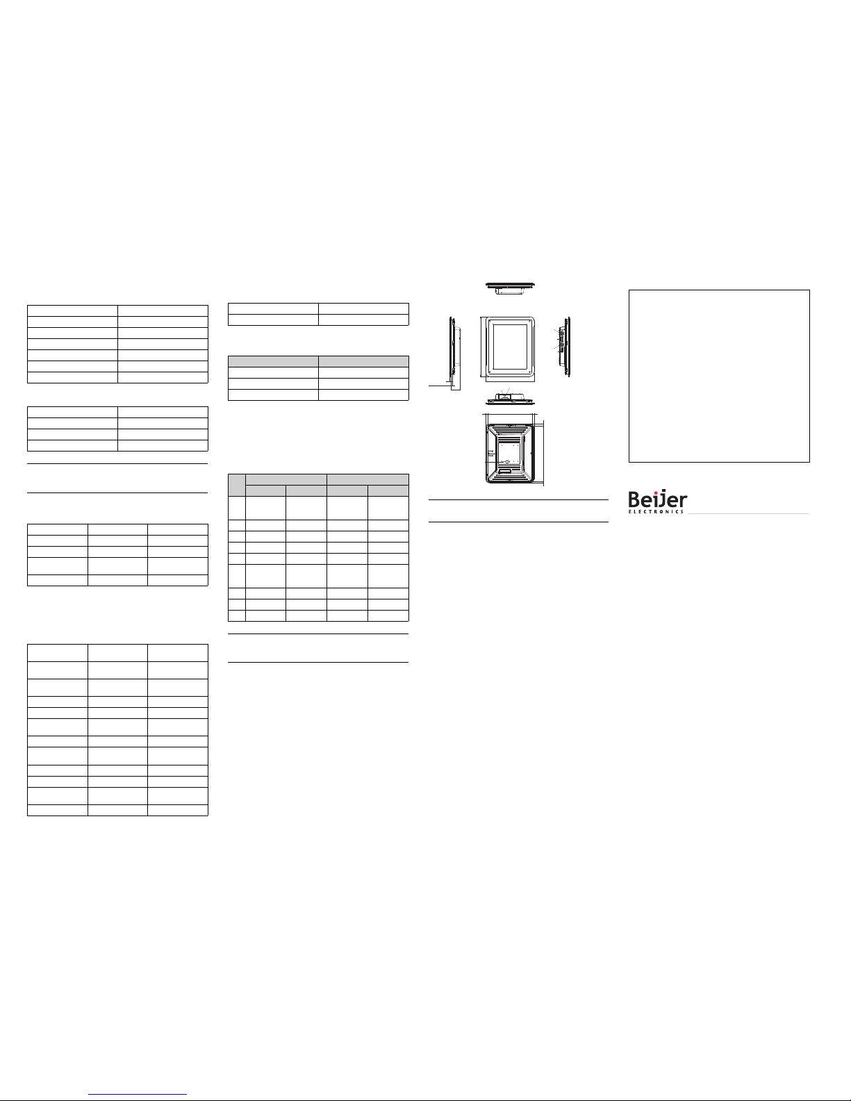
5.2 T10A Outline
280
228
max 8 mm
material thickness
7
44
262 99
209 99
USB host
SD memory
card slot
Expansion port
COM3 RS232 /
COM4 RS422/RS485
COM1 RS232 /
COM2 RS422/RS485
Ethernet
24 V DC
Note:
AStepCADfileis availableon the websit ewww.beijerelectronics.com
Orderno: MAEN017C
Copyright© 2012-04 BeijerElectronics AB.All rights reserved.
Theinformation in thisdocument is subjectto change withoutnotice and is
providedas available atthe time ofprinting. BeijerElectronics AB,including
allits group companies,reserves the rightto change anyinformation without
updatingthis publication. BeijerElectronics AB,i ncludingall its group
companies,assumes no responsibilityfor any errorsthat mayappear in this
document. Read theentire installation manualprior to installingand using
thisequipment. Onlyqualified personnel mayinstall, operate orrepair this
equipment. Beijer ElectronicsAB, including allits group companies,are
notresponsible for modified,altered or renovatedequipment. Becausethe
equipmenthas a widerange of applications,users mustacquire the appropriate
knowledgeto use theequipment properly intheir specific applications. Persons
responsiblefor the applicationand the equipmentmust themselves ensurethat
eachapplication is incompliance with allrelevant requirements, standards and
legislationin respect toconfiguration and safety. Onlyparts and accessories
manufacturedaccording to specificationsset by BeijerElectronics AB,including
allits group companies,may be used.
BEIJERELECTRONICS AB, INCLUDINGALL ITSGROUP
COMPANIES,SHALL NOTBE LIABLE TOANYONE FOR ANY
DIRECT,INDIRECT,SPECIAL, INCIDENTALOR CONSEQUENTIAL
DAMAGESRESULTING FROMTHE INSTALLATION,USE ORREPAIR
OFTHIS EQUIPMENT,WHETHER ARISING INTORT,CONTRACT,
OROTHERWISE. BUYER'SSOLE REMEDYSHALL BE THEREPAIR,
REPLACEMENT,OR REFUNDOF PURCHASE PRICE,AND THE
CHOICEOF THE APPLICABLEREMEDY SHALL BEAT THESOLE
DISCRETIONOF BEIJER ELECTRONICSAB, INCLUDINGALL ITS
GROUPCOMPANIES.
Head office
BeijerElectronics AB
Box426
20124 Malmö, Sweden
www.beijerelectronics.com/ +4640 358600
 Loading...