

Page 1
HANDLEIDING | BCI-NG NL
ENG USER MANUAL | BCI-NG
VOOR U BEGINT
Lees deze handleiding in zijn geheel voor u begint ● Neem de
veiligheidsvoorschriften van de fabrikant van het voertuig in acht ● Gebruik een
EMC goedgekeurde soldeerbout ● Knip nooit CAN-draden in het voertuig door ●
Verleng nooit de CAN-draden van de BCI-NG ● Isoleer niet-gebruikte draden ●
Zorg dat de auto niet in een zogenaamde Transportmode staat ● Test de werking
van de BCI-NG met de vier wielen van de auto op de grond.
BELANGRIJK
De installatie van de BCI-NG mag alleen door automotive specialisten worden
uitgevoerd ● Neem alle moderne kwaliteitseisen van de automotive industrie in
acht ● Houd u aan alle voorschriften van de fabrikant van de auto waarin u de BCING monteert ● Houd u aan de in het betreffende land geldende normen en
voorschriften voor de achteraf installatie in een voertuig ● Monteer de BCI-NG op
een droge plaats ● De BCI-NG voldoet aan alle eisen volgens: UNECE Regulation
Number 10.
INSTALLATIE
1. Scan de QR-code op de BCI-NG. De bijbehorende Application List wordt
geopend.
2. Vind uw auto op de Application List (mogelijk >1).
3. Klik op het bus-ID van uw keuze. U wordt doorgelinkt naar incar.beijer.com.
4. Login met het Serial No. en Password No. die op de BCI-NG staan.
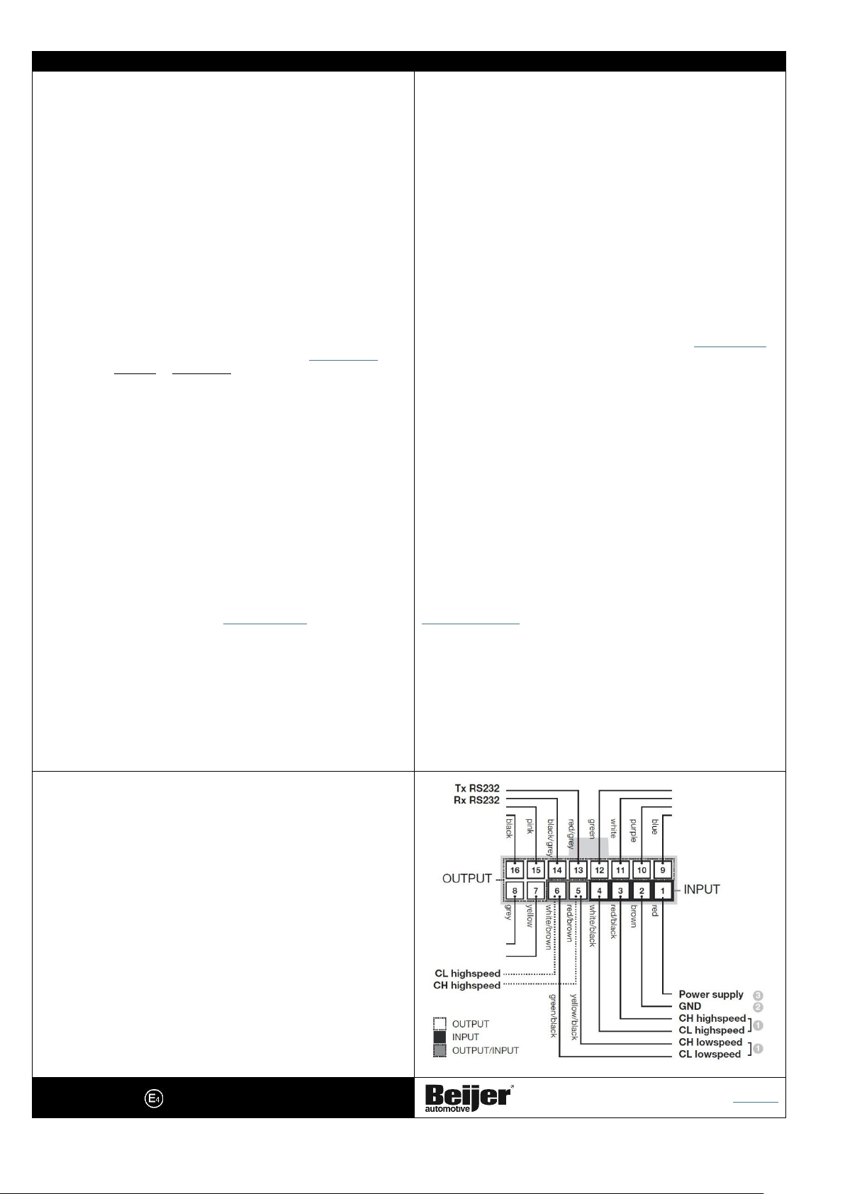
5. Sluit TWEE CAN-draden aan volgens de INCAR-instructie (CAN-FD, CANHighspeed of CAN-Lowspeed).
6. Sluit de BRUINE draad (31) aan op een deugdelijk massapunt. Bij voorkeur
hetzelfde massapunt als dat van het aan te sluiten systeem.
7. Sluit de RODE draad (30) aan op een CONSTANTE voeding (max. 2A zekeren).
Deze mag niet wegvallen, ook niet na verloop van tijd! Gebruik bij twijfel een
gezekerde voeding vanaf de 12V accu.
8. Steek de 16-polige stekker in de BCI-NG en zet direct het contact aan of zet de
auto in READY MODE (EV).
De PWR-LED zal nu branden (BCI-NG uit slaapmode) en de CAN-LED gaat snel
knipperen. Zodra de BCI-NG de auto heeft herkend (ong. 20 sec.) zal de CAN-LED
constant gaan branden en is de BCI-NG operationeel. De signaaluitgangen werken
nu zoals vermeld op de bijbehorende Application List. Na het uitzetten van het
contact gaat de BCI-NG in slaapmode (afhankelijk van het type voertuig met enige
vertraging) en gaan de PWR-LED en de CAN-LED uit.
N.B. de COM-LED brandt alleen als een BCI na installatie voertuigspecifiek is
geworden. In die status kan de configuratie van de BCI niet meer wijzigen, wat o.a.
een vast pulsgetal garandeert. Raadpleeg beijer.com/service/ voor meer informatie
over update/refurbish van een BCI-NG.
VOORWAARDEN
Dit document is vervaardigd om de gebruiker te informeren. Het mag niet worden
gewijzigd zonder toestemming vooraf van Beijer Automotive B.V.. Beijer
Automotive B.V. is niet verantwoordelijk voor gemaakte wijzigingen. Noch is Beijer
Automotive B.V. verantwoordelijk voor type- en/of printfouten, of daaruit
voorvloeiende gevolgen. Beijer Automotive B.V. is niet verantwoordelijk voor
schade en/of gevolgschade aan enig systeem of apparaat, dat door (verkeerd)
gebruik van de BCI-NG is veroorzaakt.
BEFORE YOU BEGIN
Read this manual completely before you begin ● Observe all instructions issued
by the manufacturer of the vehicle ● Use an EMC-approved soldering iron ●
Never cut CAN wires in the vehicle ● Never extend the CAN wires of the BCI-NG
● Insulate unused wires ● Make sure that the car is not in a so-called Transport
mode ● Test the operation of the BCI-NG with all four wheels of the car on the
ground.
IMPORTANT
The installation of the BCI-NG may only be carried out by automotive specialists
● Observe all modern quality requirements of the automotive industry ● Adhere
to all regulations of the manufacturer of the car in which you are installing the
BCI-NG ● Adhere to the standards and regulations applicable in the country
concerned for subsequent installation in a vehicle ● Install the BCI-NG in a dry
place ● The BCI-NG meets all requirements according to: UNECE Regulation
Number 10.
INSTALLATION
1. Scan the QR code on the BCI-NG. The corresponding Application List will open.
2. Find your car on the Application List (possibly >1).
3. Click on the bus-ID of your choice. You will be redirected to incar.beijer.com/.
4. Log in with the Serial No. and Password No. that are on the BCI-NG.
5. Connect TWO CAN wires according to the INCAR instructions (CAN-FD, CANHighspeed or CAN-Lowspeed).
6. Connect the BROWN wire (31) to a reliable ground point. Preferably the same
ground point as that of the system to be connected.
7. Connect the RED wire (30) to a CONSTANT power supply (max. 2A fuse). This
must not fail, not even after a while! If in doubt, use a fused power supply from
the 12V battery.
8. Insert the 16-pin plug into the BCI-NG and immediately switch on the ignition
or put the car in READY MODE (EV).
The PWR LED will now light up (BCI-NG out of sleep mode) and the CAN LED will
flash quickly. As soon as the BCI-NG has recognised the car (approx. 20 sec.), the
CAN LED will light up constantly and the BCI-NG is operational. The signal
outputs now work as stated on the corresponding Application List. After
switching off the ignition, the BCI-NG goes into sleep mode (with some delay
depending on the vehicle type) and the PWR LED and the CAN LED go out.
Note: the COM LED only lights up if a BCI has become vehicle-specific after
installation. In that status, the configuration of the BCI can no longer change,
which guarantees a fixed pulse number, among other things. Consult
beijer.com/en/service/ for more information about updating/refurbishing a BCI-
NG.
CONDITIONS
This document has been produced to inform the user. It may not be changed
without prior permission from Beijer Automotive B.V.. Beijer Automotive B.V. is
not responsible for changes made. Nor is Beijer Automotive B.V. responsible for
typing and/or printing errors, or the consequences thereof. Beijer Automotive
B.V. is not responsible for damage and/or consequential damage to any system
or device caused by (incorrect) use of the BCI-NG.
SPECIFICATIONS
● Protection level: IP40
● V-supply: 7.5Vdc to 32Vdc
● Maximum current consumption (unloaded):
Normal mode: < 80 mA ~ 12/24V | Sleep mode: < 2.0 mA ~ 12/ and <1.5mA ~ 24V
● CAN-FD, CAN Highspeed and/or CAN Lowspeed
● Inputs: CAN connections
● Outputs: all digital outputs are (temporarily) protected against short circuit to V-supply and
ground
Digital outputs (connector pin 11 and 12)
● Voltage range: V-supply (from 7.5Vdc to 32Vdc)
● Pull Down to ground
● Max. current: 500mA per output
Frequency/Digital outputs (connector pin 9 and 10)
● 10V with Pull Down to ground (BCI-2: V-supply with Pull Down to ground)
● Max. frequency: 2 kHz
● Max. current: 50 mA/output
Digital outputs (connector pin 7, 8, 15 and 16)
● 10V with Pull Down to ground
● Max. current: 50 mA/output
Temperature
● Operating temperature: -40°C / +85°C
European certification: 10R-06 5681
Beijer Automotive B.V.
beijer.com
Netherlands
 Loading...