

Page 1

Beijer Automotive BV | Schijndel | www.beijer.com | BCI Quickstart
Beijer Automotive BV | Schijndel | www.beijer.com | BCI Quickstart
ENGNL
Beijer Automotive BV | Schijndel | www.beijer.com | BCI Quickstart
BEFORE YOU START
Read this Quickstart completely before proceeding! Observe all instructions
issued by the manufacturer of the vehicle! Use an EMC approved soldering
iron Never cut CAN wires in the vehicle Never extend the CAN wires of the
BCI Insulate unused wires The function of each wire is speci ed on the
sticker at the bottom of the BCI and on www.in-car.nl.
IMPORTANT
The BCI may only be installed by automotive specialists Observe all modern
ENGNL
VOOR U BEGINT
Lees deze Quickstart in zijn geheel voor u begint! Neem de veiligheidsvoorschriften van de fabrikant van het voertuig in acht! Gebruik een EMC
goed-gekeurde soldeerbout Knip nooit CAN-draden in het voertuig door
Verleng nooit de CAN-draden van de BCI Isoleer niet-gebruikte draden
De functie van elke draad staat op de sticker aan de onderzijde van de BCI,
en op www.in-car.nl.
BELANGRIJK
De installatie van de BCI mag alleen door automotive specialisten wordenuitge-
voerd Neem alle moderne kwaliteitseisen van de automotive industrie in acht
Houd u aan alle voorschriften van de fabrikant van de auto waarin u de BCI monteert Houd u aan de in het betreffende land geldende normen en voorschriften
voor de achteraf installatie in een voertuig Monteer de BCI op een droge plaats
De BCI voldoet aan alle eisen volgens: Commission Directive 2004/104/EC.
INSTALLATIE
1 Sluit TWEE CAN-draden (Highspeed- of Lowspeed-bus) exact aan volgens
de In-car instructie (Login Naam en Wachtwoord op deze Quickstart).
2 Sluit de BRUINE draad (-31) aan op een goed massapunt.
3 Sluit de RODE draad (+30) aan op een CONSTANTE voeding
(max. 2A zekeren).
4 Steek de stekker in de BCI en zet ZO SNEL MOGELIJK het contact aan.
De PWR-LED zal nu branden (BCI komt uit slaapmode) en de CAN-LED snel
knipperen. Zodra de BCI de auto heeft herkend (ong. 20 sec.) zal de CAN-LED
constant branden en is de BCI operationeel. De signaaluitgangen werken nu zoals
vermeld op de sticker aan de onderzijde van de BCI. Na het uitzetten van het
contact gaat de BCI in slaapmode (afhankelijk van het type voertuig met enige
vertraging) en gaan de PWR-LED en de CAN-LED uit. NB: de COM-LED wordt
niet gebruikt.
VOORWAARDEN
Dit document is vervaardigd om de gebruiker te informeren. Het mag niet worden
gewijzigd zonder toestemming vooraf van Beijer Automotive BV. Beijer Automotive
BV is niet verantwoordelijk voor gemaakte wijzigingen. Noch is Beijer Automotive
BV verantwoordelijk voor type- en/of printfouten, of daaruit voorvloeiende
gevolgen. Beijer Automotive BV is niet verantwoordelijk voor schade en/of
gevolgschade aan enig systeem of apparaat, dat door (verkeerd) gebruik van de
BCI is veroorzaakt.
Beijer Automotive BV | Schijndel | www.beijer.com | BCI Quickstart
BEFORE YOU START
Read this Quickstart completely before proceeding! Observe all instructions
issued by the manufacturer of the vehicle! Use an EMC approved soldering
iron Never cut CAN wires in the vehicle Never extend the CAN wires of the
BCI Insulate unused wires The function of each wire is speci ed on the
sticker at the bottom of the BCI and on www.in-car.nl.
IMPORTANT
The BCI may only be installed by automotive specialists Observe all modern
quality requirements relating to the automotive industry You must observe all
instructions issued by the manufacturer of the vehicle in which you are installing
the BCI You must observe the prevailing norms and regulations in the relevant
country regarding subsequent installation in a vehicle The BCI must be installed in a dry location The BCI complies with all requirements in accordance
with: Commission Directive 2004/104/EC.
INSTALLATION
1 Connect TWO CAN-wires (Highspeed or Lowspeed) exactly according to
the In-car instruction (Username and Password on this Quickstart).
2 Connect the BROWN wire (-31) to a proper ground terminal.
3 Connect the RED wire (+30) to a CONSTANT power supply
(max. 2A fused).
4 Plug the connector in the BCI and turn on the ignition IMMEDIATELY.
The PWR-LED will light up (BCI wakes up from sleeping mode) and the CANLED will ash fast. As soon as the BCI has recognised the vehicle (approx. 20
sec.), the CAN-LED will be on continuously and the BCI will be operational. The
signal-outputs now work as described on the sticker on the bottom of the BCI.
If the ignition is switched off now, the BCI will enter sleep mode (with some delay
depending on the type of vehicle) and the PWR-LED and CAN-LED will go out.
Note: the COM-LED is not used.
CONDITIONS
This document has been created as a source of information for the user. It may
not be modi ed without the prior consent of Beijer Automotive BV. Beijer Automotive BV is not responsible for any modi cations that are made, nor for any
typing and/or printing errors, or any consequences that arise as a result thereof.
Beijer Automotive BV is not responsible for any damage and/or consequential
loss in relation to any system or device caused via the (incorrect) use of the BCI.
ENGNL
Page 2
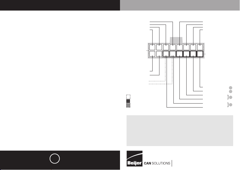
Speci cations
Protection level: IP40
V-supply: 7.5Vdc to 32Vdc
Maximum current consumption (unloaded): Normal mode:
< 80 mA ~12/24V. Sleep mode: < 1.5 mA ~ 12/24V
CAN Highspeed and/or CAN Lowspeed
Networks: Inputs: CAN connections
Outputs: all outputs are protected against shortcircuit
to V-supply and ground.
Digital outputs (connector pin 11 and 12)
Voltage range: V-supply (from 7.5V to 32V)
Pull Down to ground
Max. current: 500mA per output
Thermal protection.
Frequency/Digital outputs (connector pin 9 and 10)
10V with Pull Down to ground (BCI-2: V-Supply
[from 7.5V to 32V] Pull Down to ground)
Max. freq. 2 kHz
Max. current: 50 mA/output
Digital outputs (connector pin 7, 8, 15 and 16)
10V with Pull Down to ground
Max. current: 50 mA/output
Temperature
Operating temperature: -40 °C / +85 °C
Tx RS232
Rx RS232
OUTPUT
CL highspeed
CH highspeed
OUTPUT
INPUT
OUTPUT/INPUT
green
red/grey
black/grey
pink
black
16 15 14 13 12 11 10 9
87654321
yellow
grey
white/brown
green/black
white/black
red/brown
yellow/black
white
red/black
purple
brown
blue
INPUT
red
Power supply
GND
CH highspeed
CL highspeed
CH lowspeed
CL lowspeed
www.in-car.nl
Login voor één instructie | Log-in for one instruction
Username:
Password:
3
2
1
1
European certi cation: E4 10R-04 2371 | Patent 1024730
2565
 Loading...