

Page 1
Gerätedokumentation
Miteinander zum Erfolg
Page 2
English
en
LaserStar T Plus
DOC 86076-en/03
355.00032
Page 3

86076 DB-en/03 355.00032
Page 4
Translation of the original instructions
en
LASERSTAR T PLUS
English
355.00032
Page 5
English ⋅ LaserStar T Plus
en
This unit documentation is part of the
unit and must be enclosed when selling
or passing on the unit.
• The unit has been designed solely for use in
dental laboratories and comparable establishments for research, commercial and training
purposes. The unit must only be operated by
dental professionals, or they must provide
supervision if trainees or other persons operate
unit.
• The operating instructions must be read and
understood before the device is used. This particularly applies to the Safety information. The
warranty is void in cases of damage which is
caused by nonobservance of the operating instructions. We will also not accept liability for any
resulting consequential damages.
• Symbols used
List of contents
General information...........................................3
Safety information .............................................6
System description..........................................11
Installation.......................................................24
Operation ........................................................31
Dental instructions...........................................42
Status and error messages/
Fault clearance................................................53
Service and maintenance................................56
Marking ...........................................................66
Disposal ......................................................... 68
Index ...............................................................69
EU conformity declaration ........................ Annex
This symbol indicates very important
information. Failure to comply with it may
result in personal injury.
86076 DB-en/03 355.00032
2
Page 6

en
General information
Importance of the operating instructions
These operating instructions cover all the information that is necessary according to the relevant
regulations for the safe operation of the device
described herein.
The operating instructions are a part of the
LaserStar T Plus. These operating instructions
should therefore
• always be kept at hand near the device until the
LaserStar T Plus is disposed of,
• and should be passed on with the LaserStar T
Plus when it is purchased, sold, or lent.
Contact the manufacturer if you do not understand
something in the operating instructions.
English ⋅ LaserStar T Plus
We welcome any suggestions or criticism. Please
feel free to notify us. Your effort will help us make the
operating instructions more user-friendly and
respond more effectively to your wishes and needs.
Target group
This document is directed toward everyone who
works with this device or performs service tasks that
are described in this document.
Contact information
BEGO Bremer Goldschlägerei Wilh. Herbst GmbH & Co. KG
Wilhelm-Herbst-Str. 1
28359 Bremen
Phone: +49 421 2028-0
Service-Hotline Phone: +49 421 2028-270
www.bego.com
Copyright by BEGO Bremer Goldschlägerei Wilh. Herbst GmbH & Co. KG
This user guide is protected by copyright.
All rights reserved.
No part of this document may be reproduced without the express written permission of BEGO Bremer
Goldschlägerei Wilh. Herbst GmbH & Co. KG
86076 DB-en/03 355.00032
3
Page 7
English ⋅ LaserStar T Plus
en
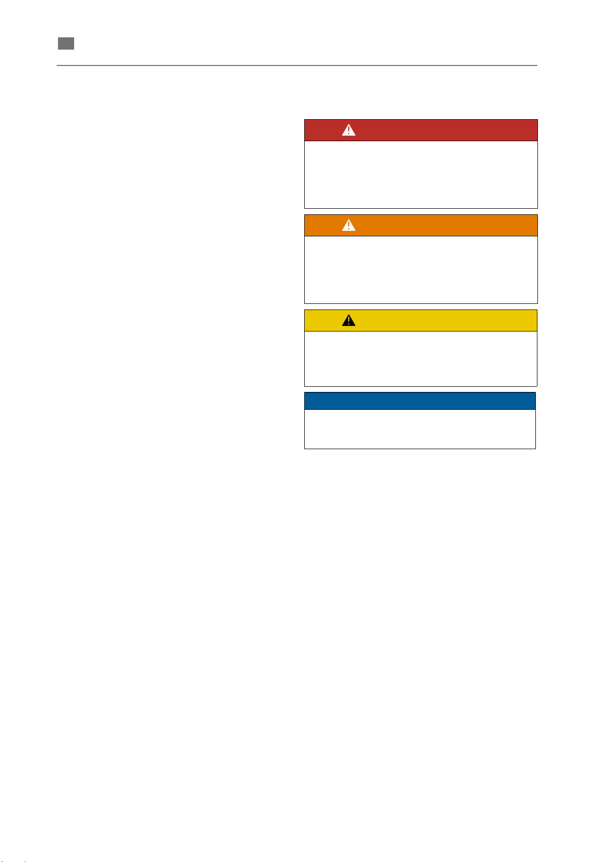
DANGER!
WARNING!
CAUTION!
NOTE
Conventions
These operating instructions contain references to
residual hazards, important user tips and handling
instructions that are identified with the following
symbols and words.
This reference identifies hazards that
can cause serious bodily injury or
death if the relevant hazard instruc-
tions are not followed or not followed
properly.
This reference identifies hazards that
can cause bodily injury or property
damage if the relevant hazard
instructions are not followed or not
followed properly
This reference identifies only those
hazards that are potential
damaging to property and the
environment.
This symbol identifies user tips and particularly
useful information. It helps you optimally exploit
all the functions of your machine.
1. Sequential actions are described in sequentially
numbered paragraphs.
In most cases, the operator's actions generate
some kind of a reaction from the system. These
reactions are identified with the symbol
→
CAPITALS If cross-references refer to other chapters or
(A) (B) (C) Capital letters in parentheses identify the position of
Cross-references are identified with the
symbol
sections the header text is written with capital
letters.
the individual elements in the associated figure.
→.
.
4
86076 DB-en/03 355.00032
Page 8

en
Warranty and liability
English ⋅ LaserStar T Plus
Our general terms and conditions of sale and
delivery apply. These are made available to the
customer on completion of the contract, at the latest.
Warranty and liability claims in the event of physical
injury or damage to property are invalid if they are
caused by one or more of the following:
• Improper use of the device;
• Improper installation, putting into operation,
operating and maintenance of the device;
• Operating the device with safety and protective
facilities that are defective, improperly installed
or inoperative;
• Failure to heed the information in this manual
concerning the transport, storage, installation,
putting into operation, operation and service
and maintenance of this device;
• Unauthorized structural modifications to this
device;
• Inadequate monitoring/checking of parts of the
device that are subject to wear;
• Improperly performed repairs;
• Catastrophes caused by alien elements or
force majeure.
Exclusion of liability in case of modifications:
If a modification by the user affects any aspect of the
performance data or intended functioning, as
described in the relevant standards, of a previously
classified laser device, the person or organization
that undertook the modification is responsible for
obtaining a new classification and new labeling for
the device. This person or organization then
assumes the status of "manufacturer".
86076 DB-en/03 355.00032
5
Page 9

English ⋅ LaserStar T Plus
en
Safety information
This section contains generally applicable safety
instructions. The machine can only be operated
safely when these safety instructions are understood and observed.
Additional special safety instructions are mentioned
in the description of the corresponding step.
Moreover, all regulations for accident prevention
valid for the current place of installation must be
complied with, especially the BGV B2 "Laser
Radiation" or the equivalent national or international
regulations (e.g. EC Directive 60825 or IEC Publication 825).
The LaserStar T Plus welding laser is a
Class 4 laser device.
The generated laser beam is invisible to the human
eye since it is at a wavelength of 1064 nm in the
near infrared range.
The high output of the laser beam can cause serious
eye damage or burn the skin when working with an
unshielded laser. Leakage radiation is also
hazardous.
However, this hazard exclusively exists when the
machine is improperly used (
USE) or during service tasks when the machine is
turned on and open with bridged safety switches.
These service and maintenance activities may only
be performed by authorized personnel (
SERVICE AND MAINTENANCE).
→ section IMPROPER
→ section
Product safety
The device described here is constructed according
to the state-of-the-art and recognized rules of safety.
Nevertheless, unavoidable residual dangers to
persons and property can arise from the LaserStar
T Plus that cannot be eliminated by the design of the
machine or constructive measures.
Therefore anyone transporting, setting up,
operating, servicing and repairing the LaserStar T
Plus must be instructed and understand the
potential dangers.
Carefully read, understand and observe the
operating instructions and especially the safety
instructions.
A lack of or insufficient knowledge of the operating
instructions negates all claims of liability against the
company BEGO Bremer Goldschlägerei Wilh.
Herbst GmbH & Co. KG.
Proper use
The LaserStar T Plus is designed exclusively for
welding metals and metal alloys. To use it for any
other purpose or for anything beyond this is to use it
improperly.
Proper use also includes:
• following all the instructions and heeding all the
information in this manual and
• the compliance of all necessary inspection and
maintenance intervals.
Only use the device if all safety mechanisms are
properly functioning.
Malfunctions that may have negative consequences
for safety must be dealt with immediately.
Improper use
The laser radiation produced by this laser device is
capable of melting, burning or vaporizing almost any
material. Depending on the composition of the
workpiece, gases and vapors dangerous to health
may be produced.
The exhauster is not designed to filter such gases or
vapors adequately.
Note: Using this device on non-metallic
materials, especially plastics, therefore constitutes improper use.
Improper use includes the following:
• Operating the device with open covers and/or
safety elements that are bridged or rendered
inoperative,
• Welding of materials that generate harmful
gases or vapors without a suitable filter and
suction unit,
• Operation in explosion-protected areas and in a
dusty or moist environment.
BEGO Bremer Goldschlägerei Wilh. Herbst GmbH
& Co. KG assumes no liability for damage arising
from improper use.
86076 DB-en/03 355.000032
6
Page 10

English ⋅ LaserStar T Plus
en
Structural modifications to the laser device
Do not make any modifications or additions to the
laser device without the permission of the manufacturer.
Only use original replacement parts and wearing
parts (
→ section MATERIAL in chapter SERVICE
AND MAINTENANCE). There is no guarantee that
parts purchased from third parties are constructed
and manufactured to meet stress and safety
requirements.
Hazardous areas
Particularly hazardous areas on the device are
identified by warning and reference signs. The
individual signs and the locations on the system
where they should be affixed are described in
section WARNING SIGNS AND INFORMATION
SIGNS.
See also the section HAZARDS DURING NORMAL
OPERATION.
→
Safety switch
Each time before the machine is turned on, the
safety switches (interlock switches) of the working
chamber door must be checked for proper operation
(
→ section CHECK SAFETY EQUIPMENT).
The safety switches may not be removed or bridged.
The danger otherwise exists that an uncontrolled
laser beam will cause serious eye damage or skin
burns.
Personal protective equipment
While properly using the machine, the eyes are
protected against damaging effects of the laser
beam and against the UV radiation arising in the
welding plasma and hazardous to the eyes while
observing the welding process (
→ section DANGER
FROM THE LASER BEAM).
Organizational and personnel
measures
Safety and monitoring devices
EMERGENCY STOP devices
The device is equipped with the following
EMERGENCY STOP facility:
• EMERGENCY STOP button on the left exterior
of the device:
This button disconnects the laser power supply
from the mains. The heat exchanger and control remain on.
Note: Take note of the discharge time of the
capacitor bank!
Protective coverings
Each time before turning on the machine, all covers
must be properly mounted.
Obilgations of the employer
The employer undertakes not to allow anyone to
work with this device unless they
• are familiar with the basic regulations concerning safety at work and accident prevention and
have been instructed in the use of this device;
• have read and understood the chapter concerning safety and the warnings in this manual and
have confirmed this by their signature;
• have been instructed as to the dangerous
effects of laser radiation in accordance with the
valid regulations about accident prevention for
laser radiation BGV B2 or the equivalent national or international regulations (e.g. EC Directive 60825 or IEC Publication 825).
The operator is also required to:
• immediately notify the responsible trade association of the initial startup of this laser device
as well as the agency responsible for occupational safety (labor inspectorate)
(
→ Accident prevention regulation BGV B2
"Laser beam"),
1)
86076 DB-en/03 355.000032
1)
A regular letter is sufficient for notification of the first startup of a laser device. Attach a copy of the CE statement of conformance and the clearance certificate.
We recommend using the "Laser notification form" accompanying the operating instructions.
7
Page 11

English ⋅ LaserStar T Plus
en
• to instruct personnel at regular intervals,
• to ensure that safety and hazard instructions for
the machine remain legible (
NING SIGNS AND INFORMATION SIGNS,
and
→ section WAR-
Obilgations of personnel
All those who work with the device must undertake
beforehand to
• comply with the basic regulations on safety at
work and accident prevention for laser radiation, BGV B2, or the equivalent national or international regulations (e.g. EC Directive 60825 or
IEC Publication 825);
• to read the chapter concerning safety and the
warnings in this manual and to confirm this by
their signature.
Personnel qualification
Only personnel properly trained and instructed
about the dangers of laser radiation as required by
the BGV B2 regulations on accident prevention for
laser radiation or the equivalent national or international regulations (e.g. EC Directive 60825 or IEC
Publication 825) are allowed to work with the device.
Trainees are only allowed to work with this device
under the supervision of someone who is an experienced user.
The service tasks described in these operating
instructions may only be done by persons who,
apart from the above-cited qualifications, have been
correspondingly trained at BEGO Bremer
Goldschlägerei Wilh. Herbst GmbH & Co. KG.
Hazard during normal operation
Danger from the laser beam
The welding laser LaserStar T Plus is a Class 4
laser device.
Due to its fully enclosed design and the safety
elements this classification is restricted to potential
skin damage of the hands caused by faulty
operation during proper use, and to maintenance
work on the laser.
a restricted burn on his hand or finger
(
→ section WHAT TO DO IF YOU RECEIVE A
BURN).
• Eye protection
As far as eye protection is concerned, this
device fulfills the requirements that apply to a
class 1 laser device for the absolute safety of
the operator and anyone else in the laser working area (document of compliance).
This assumes however that the protective laser
glass of the observation window is kept clean
and is in a technically serviceable state.
• Laser protective window
Once the laser protective window becomes
defective (scratches, fractures, chips, cracks or
discoloration from solvents), it needs to be
covered and immediately exchanged with an
intact laser protective window.
Make sure that the laser protective window is
firmly seated in the frame.
In both cases, the danger exists that an uncontrolled laser beam will cause serious eye damage or skin burns.
Blinding hazard
Due to the thermal effect of the laser beam,
secondary radiation arises from most materials that
can be briefly watched through the laser protective
window without damaging the eyes.
This secondary radiation can cause blinding only
when observed for a long time as is the case with
the long unprotected observance of halogen lamps,
headlights or the sun.
Fire hazard
The high output of the laser can cause many
materials to burn.
For this reason, no containers with easily flammable
or explosive solvents or cleansers or flammable
material (such as paper or thin pieces of wood) may
be in the working chamber during laser operation.
• Danger to hands
In normal operation, operators can accidentally
pass their hand in front of the pulsing laser
beam. In this case, the operator would receive
86076 DB-en/03 355.000032
8
Page 12

English ⋅ LaserStar T Plus
en
Harmful gases and vapors
The device is equipped only with a simple air filter
and a fan to extract welding gases and fumes from
the working chamber. The air filter consisting of a
spark protection mat and a filter fabric
(
→ REPLACING THE AIR FILTER).
When working with metals or metal alloys that may
release harmful substances when heated or
vaporized, an external extraction and filter unit must
be connected.
Noises
The continuous sound level produced by the device
is always less than 60 dB(A).
Specific safety information
Normal welding mode
The following instructions must be observed during
proper use of the device (if your hands are in the
working chamber):
What to do if you receive a bum
If you suspect that you have been burned your eyes,
immediately notify the laser safety supervisor or the
safety expert, and consult a doctor if necessary.
If you receive a burn from a laser pulse on your
finger or hand, treat the wound (obtain medical
assistance if the burn is strong enough). Although a
small burn is not particularly critical, you should still
make sure that no infection results.
Handling deionised water (cooling water)
In the inner cooling circuit of the laser, twice-distilled
and deionised water is used as coolant.
When using this water, do not let it contact your skin
and especially the mucous membrane of the eyes,
nose and mouth.
Immediately dry the wet spots on your skin with a
clean cloth or flush the wetted mucous membrane
with tap water.
Serving and maintenance
• When positioning the workpiece, always make
sure that both arms are firmly lying in the rings
of the hand openings. This allows you reliably
and calmly move the workpiece into the correct
position for welding.
• Fingers and hands may not be positioned near
the laser beam due to the burn hazard. This
area is identified by cross-hairs when you
watch through the microscope.
• Do not wear shiny jewelry (rings, watches, bracelets). Depending on their surface properties,
they may focus the scattered radiation and thus
cause slight skin burns. Leakage radiation that
is emitted by the welded material can also cause small burns on the surface of the hand under
certain unfavorable circumstances.
• Be calm and concentrate when triggering laser
pulses.
• For subsequent pulses, always use the microscope to check that the workpiece is positioned
correctly.
General instructions
• Any one operating, servicing and repairing the
laser device must have read and understood
the safety instructions in this instruction handbook.
• Check for loose screw connections and tighten
them after reinstalling.
• After servicing is finished, the operation of all
safety devices must be checked.
Tasks that can be performed by the operator
The operator may only perform service and maintenance tasks that are described in this instruction
handbook.
When doing these tasks,
• always pull the power plug and
• observe the special safety instructions in the
corresponding sections.
86076 DB-en/03 355.000032
9
Page 13

English ⋅ LaserStar T Plus
en
Jobs that may only be done by authorized
service personnel
All service and maintenance tasks that are not
described in this instruction handbook, especially
work on the electrical supply, live parts and components of the laser head, may only be done by authorized service technicians who meet the following
qualifications:
• precise understanding of accident prevention
regulation BGV A2 "Electrical systems and
equipment", and accident prevention regulation
BGV B2 "Laser beam" or equivalent national or
international regulations (e.g. EC Directive
60825 or IEC Publication 825),
• precise understanding of device-specific functions and hazard sites such as high-voltage
parts, safety circuits and laser beam guidance.
86076 DB-en/03 355.000032
10
Page 14
en
System description
Overall view
English ⋅ LaserStar T Plus
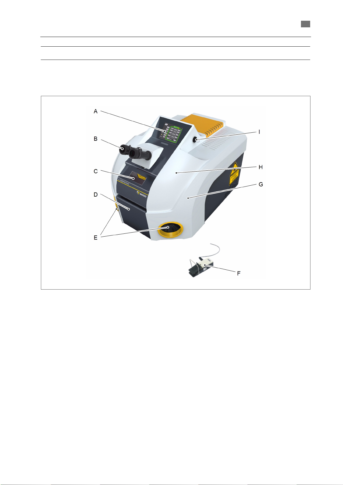
Fig. 1 Overall view
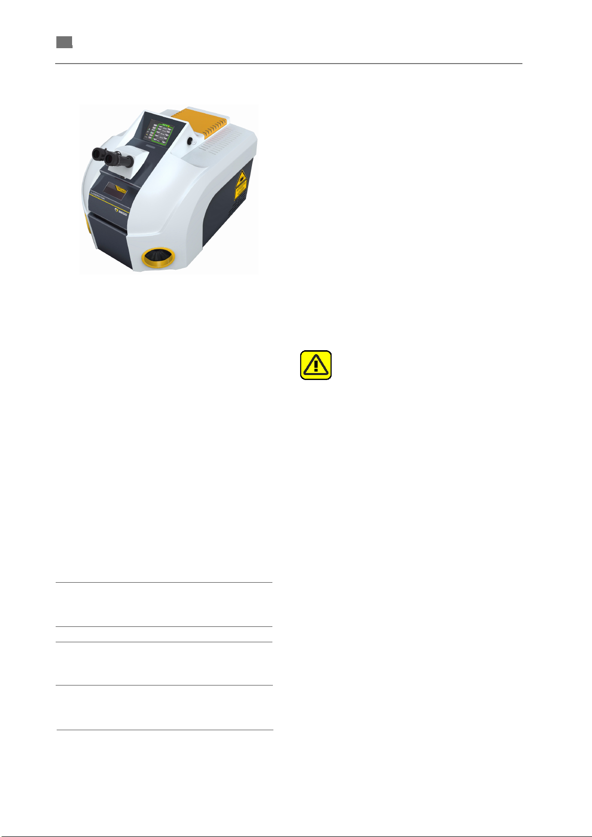
The Fig. 1 provides an overall view of the laser system when closed. The individual function elements are
identified by capital letters and defined below.
(A) Touch screen
(B) Stereo microscope
(C) Observation window with laser protective
glass
(D) Working chamber door
(E) Hand openings
(F) Pedal switch for triggering laser pulses
and controlling inert gas and exhauster
(G) Working chamber
(H) Removable cover
(I) Key switch
86076 DB-en/03 355.00032
11
Page 15

English ⋅ LaserStar T Plus
en
Technical Data
Dimensions and weight Width x height x depth
(maximum)
Weight (about) 60 kg
Electrical data voltage - frequency - power
consumption - phases
Energy consumption
- max.(230 V)
- Standby
- ECO-Modus
Laser data Laser crystal Nd:YAG
Wavelength 1,06 μm
Power 60 W
Pulse peak power 8 kW
Pulse energy 60 J
Pulse frequency Single pulse, 1 ... 50 Hz
Focal diameter 0,2 ... 2,6 mm
Laser class closed:
Laser class open:
Elektromagnetic compatibility
(EMC)
The device meets the requirements of the EMC directive. The test was
carried out on the basis of the relevant standards for the purpose of
classification.
540 x 460 x 690 mm
230 V - 50/60 Hz - 10 A (1 phase)
110 V - 60 Hz - 13 A (1 phase)
1,7 kW
0,2 kW
0.01 kW
4 (document of compliance
included)
4
The actual data can differ depending on the device features.
86076 DB-en/03 355.00032
12
Page 16
en
Display and operating elements
English ⋅ LaserStar T Plus
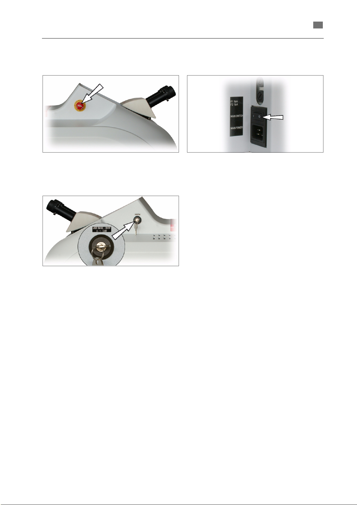
EMERGENCY STOP button
Fig. 2 EMERGENCY STOP button on the left side
Key switch
Main switch
Fig. 4 Main switch on the rear side
Fig. 3 Key switch on the right side
Key switch LASER EIN / AUS - ON / OFF
0 Off position: the key switch should be
in this position prior to turn on the
main switch.
1 Processor boots up, software is
started.
START Lamp power supply is switched on,
laser flash lamp is ignited.
Opposite to the switch positions 0
and 1 the Start position is a
momentary position (the key switch
does not remain in this position).
86076 DB-en/03 355.00032
13
Page 17
English ⋅ LaserStar T Plus
en
NOTE
NOTE
Touch screen
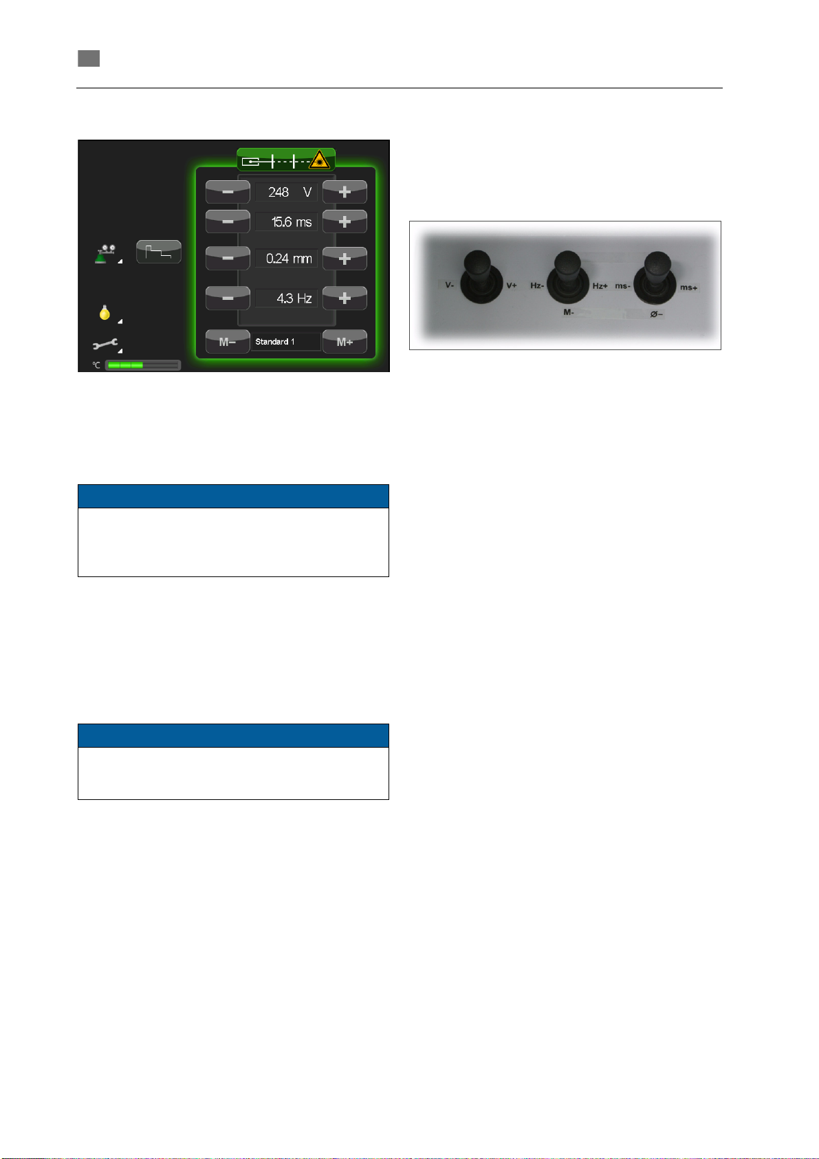
Fig. 5 Main menu
All of the functions of the laser can be executed by
touching the symbols or texts on the touch screen.
When touching small symbols (such as using the
keyboard of the
WINDOW), it is recommendable to use a thin but
not sharp object.
→ ALPHANUMERIC INPUT
Operating elements in the working chamber
The main functions can be controlled by the
operating elements on the console inside the
working chamber.
Fig. 6 Control elements in the working chamber
V– / V+ Change the current value for the
lamp voltage
M– / M+ Select the memory location number
for saving / loading laser parameter
sets (see sections SAVING LASER
PARAMETERS and LOADING
LASER PARAMETERS).
Hz– / Hz+ Set the pulse frequency.
Ø– / Ø+ Set the diameter of the focal spot.
The Fig. 5 shows the main menu for an operating
mode in which not all the functions are activated.
Depending on the current operating mode, a few of
the shown symbols may be missing.
Some functions are only optional.
The individual functions of the main menu and
the submenus are explained in the section
DESCRIPTION OF THE MENUS.
ms– / ms+ Set the required value for the
duration of the laser pulse.
Footswitch
The unit comes standard with a digital footswitch for
triggering pulses and - depending on the configuration and setting of the device - for switching the
exhauster and the inertgas.
The footswitch is connected to the system with
flexible cable and can be moved into any position
comfortable for the operator. The footswitch is
equipped with a strap to easily draw the footswitch
towards the user.
14
86076 DB-en/03 355.00032
Page 18
en
Interlock circuit
English ⋅ LaserStar T Plus
The LaserStar T Plus is equipped with a safety
circuit (Interlock circuit).
This interlock circuit, together with the laser shutter,
ensures that no hazardous laser radiation is emitted
from the device during operation.
The status of the laser shutter is displayed on the
touch screen
It is influenced by the status of the working chamber
door.
→ SHUTTER STATUS DISPLAY).
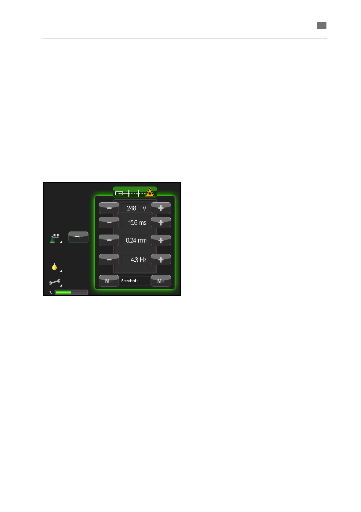
Descriptions of the menus
Main menu
The laser shutter can only be opened when:
• the working chamber door is closed, and
• there is no disturbance in the power supply or
the cooling circuit.
After the system is turned on, the → MAIN MENU is
displayed. All available functions and dditional
submenus can be retrieved from this menu.
Fig. 7 Main menu
86076 DB-en/03 355.00032
15
Page 19
English ⋅ LaserStar T Plus
en
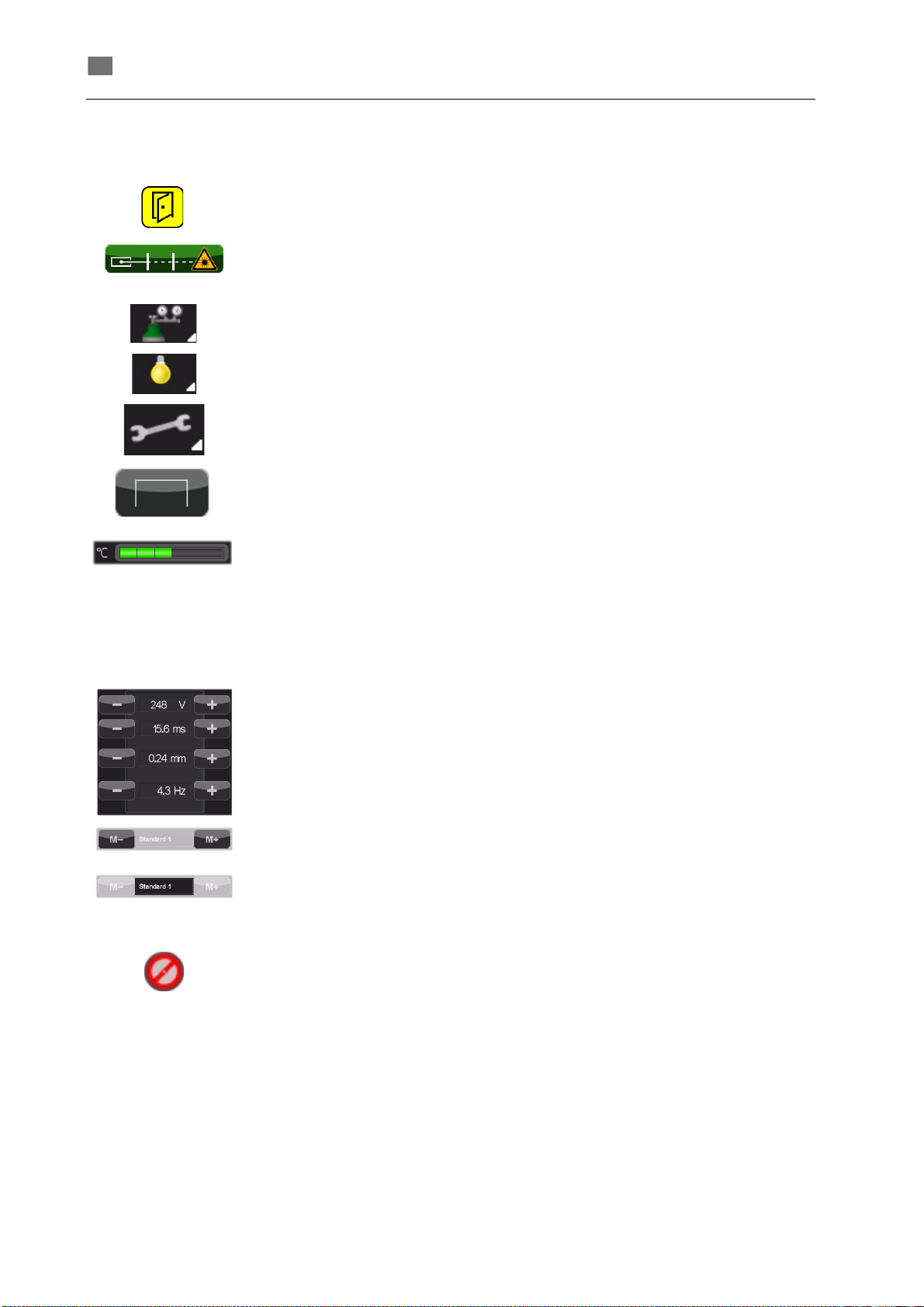
Main menu elements and their functions
Display of status and error messages (in the example above: Working chamber
door is open).
Button:
Display:
Open and close the shutter
Shutter status
(for details
→ SHUTTER STATUS DISPLAY)
Activates the inert gas feed.
Opens the window for setting the workpiece illumination (
→ SETTING
WORKPIECE ILLUMINATION).
Opens the
Opens the pulse shape editor (
→ SERVICE MENUS.
→ RETRIEVING AND EDITING PULSE SHAPES).
Display of the current temperature of the cooling water circuit:
Green: normal operating temperature
Orange: increased operating temperature
Red static: max. operating temperature reached
Red static: max. operating temperature exceeded
risk of shutdown
Laser parameter area:
Display and setting of the laser parameters (details
→ SETTING THE LASER
PARAMETERS IN THE MAIN MENU)
16
Touch these buttons to load the laser parameters stored under the previous
storage space [ M- ] or next storage space [ M+ ].
Display of the storage space name under which the currently loaded laser
parameters are saved.
Touch the storage space name to open the memory manager (
→ sections
SAVING LASER PARAMETERS and LOADING LASER PARAMETERS).
This symbol indicates features that are turned off or are not active.
86076 DB-en/03 355.00032
Page 20
en
Shutter status display
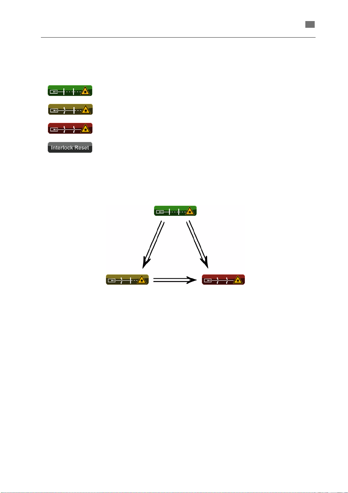
Press the Shutter button
in the working chamber
while
the working chamber door is closed.
Close working chamber door.
Touch this button
while the
working chamber door is open.
The current operating state of the laser shutter is
shown with the following symbols
Unit is ready for operation.
The laser shutter is not enabled and can not be opened.
The laser shutter is enabled, but closed because the safety circuit is open (e. g.
the working chamber door is open).
The laser is ready to emit laser pulses (i.e. the laser shutter has been enabled and
is open).
After a technical malfunction, the device is blocked.
Once the malfunction has been eliminated, it must be acknowledged with this
touch button.
How to operate
English ⋅ LaserStar T Plus
(solid vertical bars symbolize that the laser beam is
blocked) and colors.
86076 DB-en/03 355.00032
17
Page 21
English ⋅ LaserStar T Plus
en
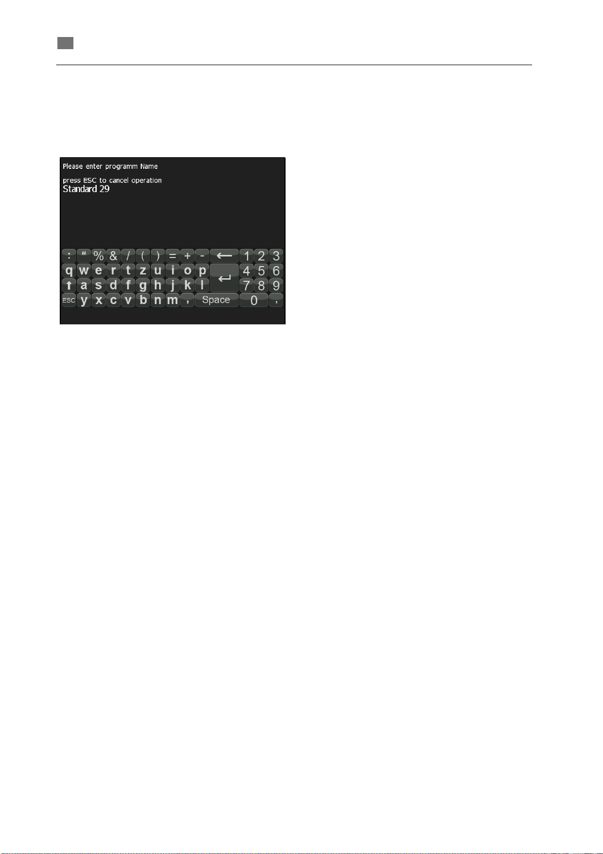
Alphanumeric input window
The touchscreen shows a window with an alphanumeric keyboard if any numeric value for parameters
or names for storage spaces or pulse shapes are to
be entered (see following example).
Fig. 8 Alphanumeric input window
General Functions
The following functions are basically available in this
input window.
Service menus
The service menus are divided into four levels with
different access rights.
User: Each user without restriction,
no password is necessary
Engineer: Technically knowledgeable user,
generally the supervisor of the
customer
The password (factory setting "e" heed the case sensitivity) can be
changed by the engineer.
Service: Service personnel trained and autho-
rized by BEGO,
Password-protected
Setup: Only employees of BEGO,
Password-protected
General instructions concerning the service menus
The following buttons are generally available in the
service menus.
• Cursor position
If a text or a number is indicated, immediately
after having opened the input window the (invisible) cursor is positioned at the end of the input
line (in the example right of numeral 9).
Prior to enter a new text delete the indicated
text step by step with the [
•Button [
Use this button to switch the indicated keyboard
for the input of capitals. Touching the button
again (in capital mode) switches back to the
input of lower case characters.
•Button [
This button closes the input window. the
entered values or texts are taken to the higherlevel window.
]
]
] button.
[ Back ] /
[ Forward ]
[ User ] /
[ Engineer ]
[ Service ] /
[ Setup ]
[ Close ] Close the service menu with this
This buttons switch you to the
next or prior menu page.
These buttons open the menus
for the corresponding service
level (having entered the correct
password).
button.
Any settings that have been
made are accepted.
86076 DB-en/03 355.00032
18
Page 22
en
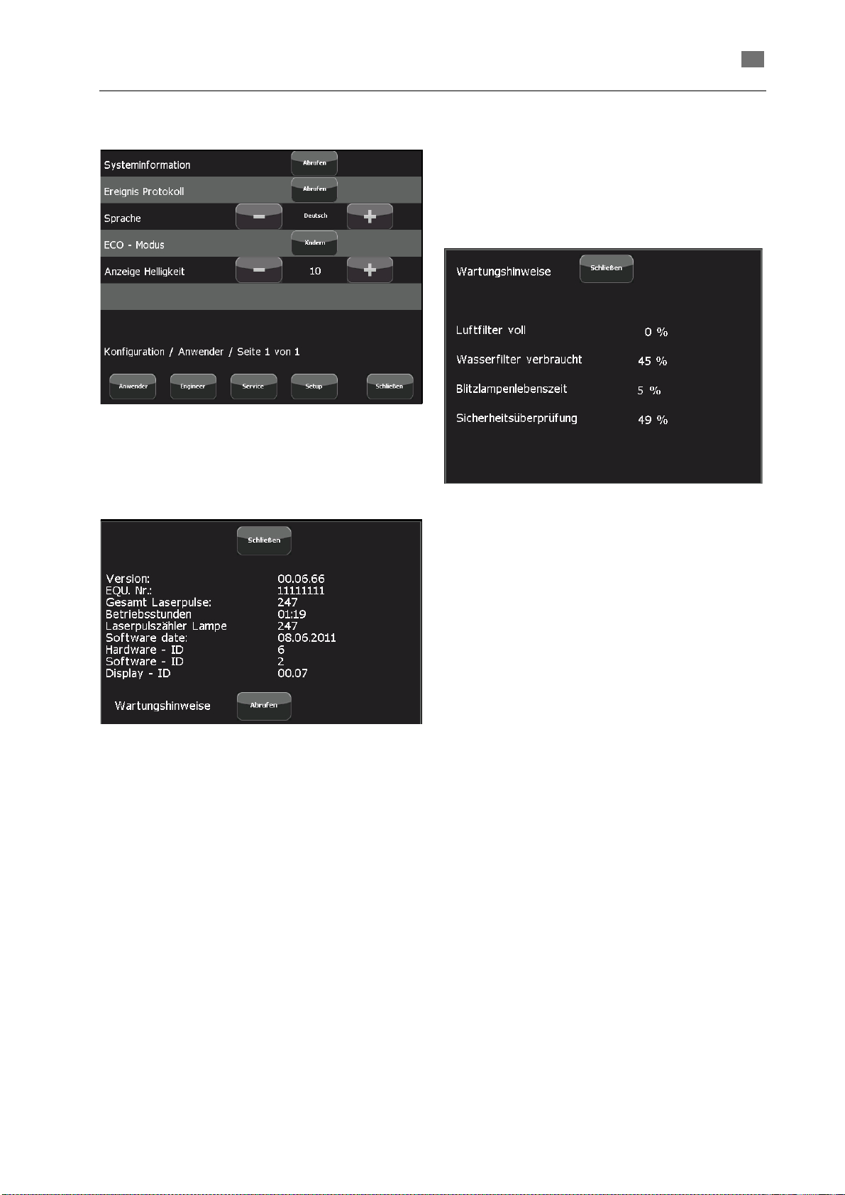
Service menu USER
Fig. 9 Service menu - User level
Sysinfo
The [ Get ] button opens the following window to
indicate system information.
English ⋅ LaserStar T Plus
The indicated values represent the percentage for
the respective events in relation to the defined thresholds (for details see the following description).
The [ Get ] button of the Sysinfo window opens the
following window.
Fig. 11 Maintenance recommendation
Fig. 10 Sysinfo
Maintenance recommendation
Basics
The system automatically generates and displays
maintenance recommendations for the events
displayed in the window below.
The maintenance recommendation messages are
displayed not immediately after having reached the
respective threshold but only after the following
conditions:
• ECO-Modus has been finished, or
Extraction filter degeneration
This feature is not used.
Water filter degeneration
This relative value refers to the conductivity measurement of the deionized water of the lamp cooling
circuit.
Lamp degeneration
This value is the relative number of laser pulses
emitted since the last lamp counter reset relative to
the setting of the Lamp warn level in the Lamp
settings dialog of the
→ SERVICE MENU
ENGINEER.
Safety check
Elapsed time relative to the fix predetermined check
interval.
• system has been switched on, or
• six hours have passed since a condition for a
maintenance recommendation is complied with
without any of the above mentioned actions
have occured.
86076 DB-en/03 355.00032
19
Page 23
English ⋅ LaserStar T Plus
en
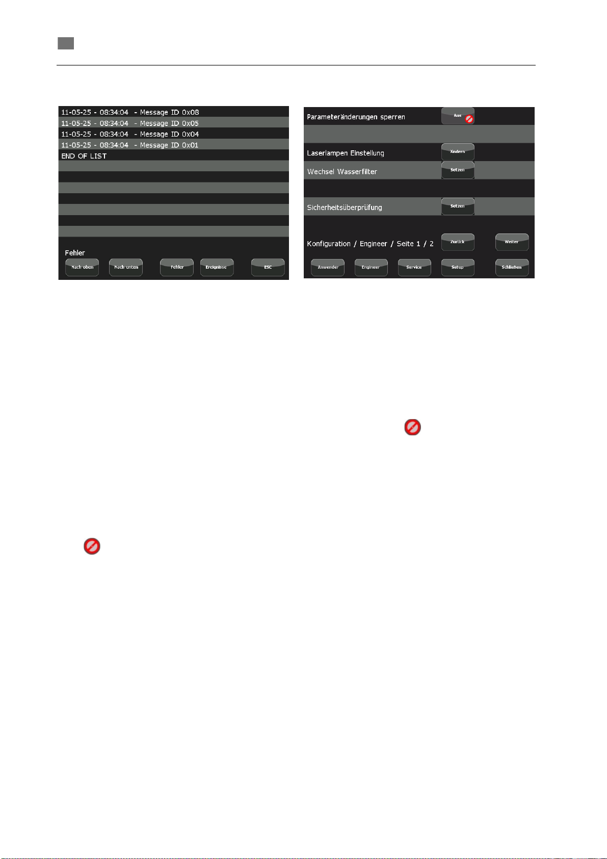
History
Fig. 12 History
The [ Get ] button of the → SERVICE MENU USER
opens the window to indicate the event logs.
With the following button you can call two different
event logs.
[ Errors ] List of errors
[ History ] List of relevant events
Use the [ Up ] and [ Down ] buttons to scroll within a
list of more than 12 entries.
Language
Use the [ - ] / [ + ] buttons to select the language for
the user interface.
ECO-Modus
The [ Change ] switches on or off the power saving
mode (
→ ECO-MODUS SETTINGS).
If the symbol is indicated in the [ Change ]
button the ECO-Modus is disabled.
Service menu ENGINEER
Fig. 13 Service-Menü Engineer-Ebene/Seite 1
Engineer level / page 1
Having entered the engineer password the engineer
level consisting of two pages is indicated.
LASER parameter lock
Use the button in this line to lock or enable the
change of the laser parameters in the main menu.
The button text shows the current state:
[ Off ] with the symbol :
The lock is disabled; you can set the laser
parameters in the main menu.
[ On ]:
Changing laser parameters in the main menu
impossible. The display shows the message
LOCKED if any locked function or button has been
selected.
Display brightness
Use the [ - ] / [ + ] buttons to adjust the brightness of
the touchscreen to the environmental conditions.
86076 DB-en/03 355.00032
20
Page 24
English ⋅ LaserStar T Plus
en
NOTE
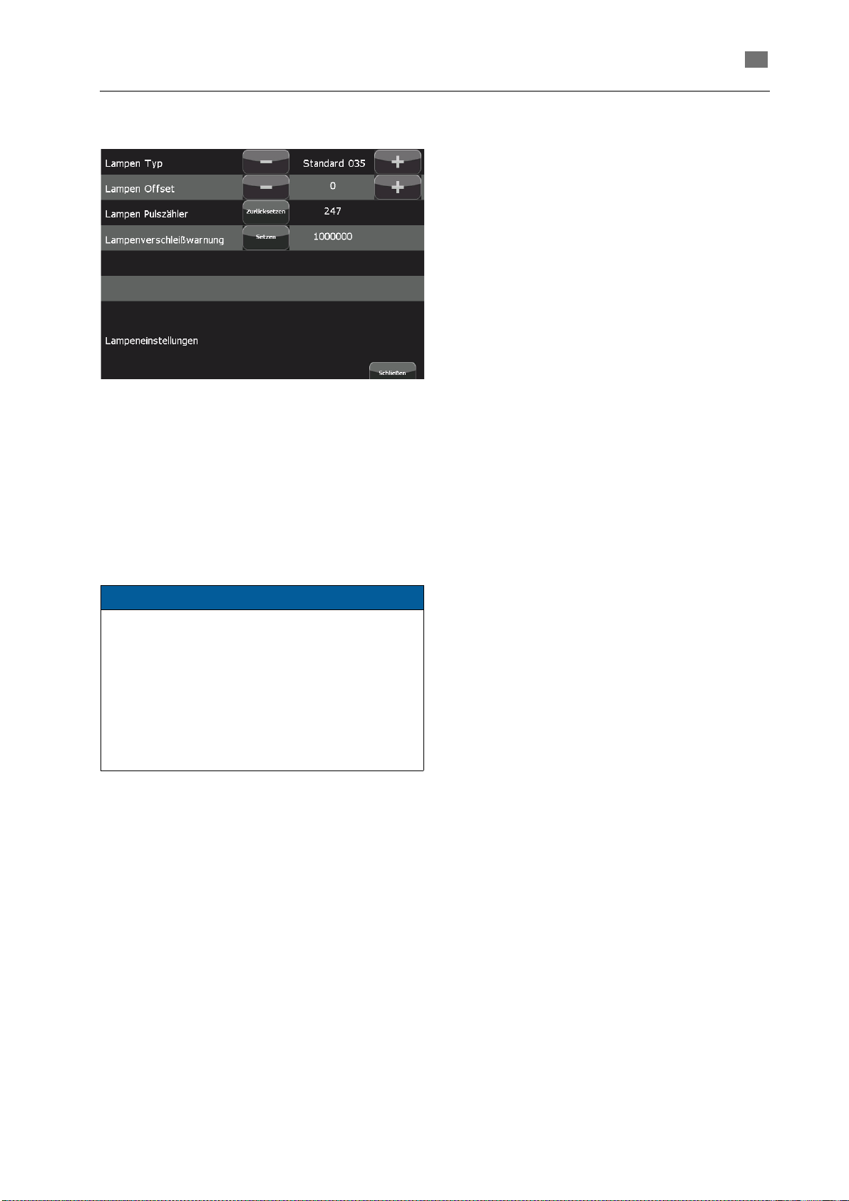
Lamp settings
Fig. 14 Lamp settings
The [ Change ] button opens the following dialog:
• Lamp type
Use the [ - ] / [ + ] buttons to select the lamp type
installed in the system.
• Lamp offset
Use the [ - ] / [ + ] buttons to change the lamp
offset value.
Lamp pulse counter
The [ Reset ] button resets the counter to zero (after
lamp replacement).
It is recommended to confirm the replacement
otherwise the system generates repeatedly inappropriate maintenance recommendations.
Lamp warn level
The [ Set ] button opens the
INPUT WINDOW to enter the number of pulses
used as threshold for the maintenance recommendation for a lamp replacement.
Change water filter
The [ Set ] button opens the
INPUT WINDOW in order to confirm the
replacement of the water filter.
It is recommended to confirm the replacement
otherwise the system generates repeatedly inappropriate maintenance recommendations.
If you confirm the replacement of the water filter
without having replaced it the laser may be
damaged.
→ ALPHANUMERIC
→ ALPHANUMERIC
In the course of time the energy of laser pulses is
reduced due to aging effects of the laser flash
lamps. You can compensate this effect by adding
an offset to the lamp voltage.
Furthermore you can use the lamp offset, to
calibrate the laser pulse energy when using
different laser systems or after a lamp
replacement. In this cases negative lamp offsets
may be useful.
86076 DB-en/03 355.00032
21
Page 25
English ⋅ LaserStar T Plus
en
NOTE
Engineer level/Page 2
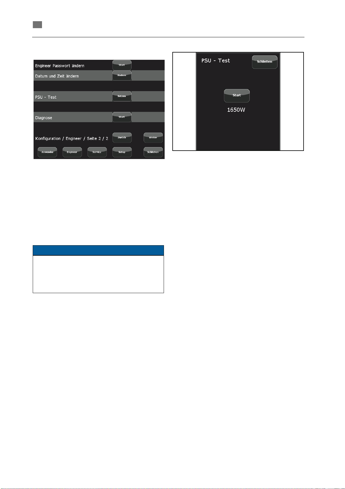
Fig. 15 Service menu - Engineer level / page 2
Change engineer password
The [ Start ] button opens the
INPUT WINDOW to enter a new engineer
password.
→ ALPHANUMERIC
Fig. 16 PSU test
The [ Start ] button initiates a PSU test. The button
text changes to [ Working ] on inverted background
as long as the test is running.
When the test has been finished the power that can
be achieved is indicated underneath the button.
Change date and time
The [ Change ] button opens a dialog to set date and
time.
It is important to set date and time correctly in
order to obtain a reliable history.
This is also important, inter alia for the maintenance recommendations that are generated by
the system.
PSU test
Basics
The PSU test ascertains the real maximum power
that can be achieved with
• the current mains supply (230 V or 110 V),
• the currently installed power supply unit (PSU)
and
• the currently installed laser lamp.
This test has been performed at the factory with a
supply voltage of 230 V. The test must be performed
by the customer only if the system is operated at
110 V. (The version for 110 V is an optional system
configuration.)
The [ Set ] button opens the following window.
86076 DB-en/03 355.00032
22
Page 26
en
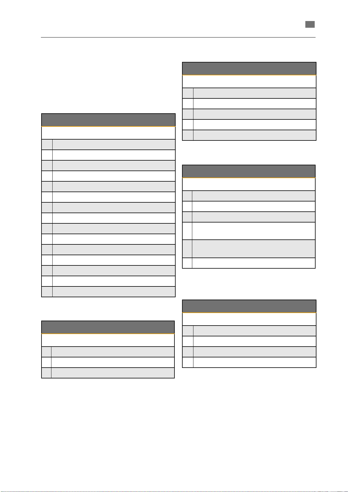
Diagnosis
The [ Start ] button opens a window with several
pages where the current status of all observed
inputs and outputs are indicated.
Depending on the system configuration not all listed
inputs and outputs (see tables below) are active.
In the case of a telephone diagnosis by our service,
the states are requested.
English ⋅ LaserStar T Plus
SHUTTER-I/O
1 Shutter1_Error HIGH
2 Shutter1_Error HIGH
SAFETY-I/O
1 EMYC_CNC HIGH
2 Light_barrier_L1 LOW
3 Light_barrier_L2 HIGH
4 Light_barrier_R1 LOW
5 Light_barrier_R2 HIGH
6 Door_L1 HIGH
7 Door_L2 LOW
8Door_R1 HIGH
9 Door_R2 HIGH
10 Hand_L1 HIGH
11 Hand_L2 HIGH
12 Hand_R1 HIGH
13 Hand_R2 HIGH
14 Safety_Customer HIGH
3 2nd_Shutter_EN LOW
4 Shutter_Open HIGH
5 Shutter_Close LOW
Fig. 19 Diagnosis menu page 3/5
BEAM-FORMING-I/O
1 Microweld_AKT HIGH
2 Microweld_POS1 LOW
3 Microweld_POS2 HIGH
Beam-Expander_END_
4
SWITCH 1
Beam-Expander_END_
5
SWITCH 2
HIGH
HIGH
6 Beam-Expander_POS 80 HIGH
Fig. 20 Diagnosis menu page 4/5
15 Fatal_Error LOW
Fig. 17 Diagnosis menu page 1/5
HEX-I/O
1 FLOW 208 HIGH
2 Temperature HIGH
3 Level HIGH
Fig. 18 Diagnosis menu page 2/5
86076 DB-en/03 355.00032
PSU-I/O
1 TOTX_EN HIGH
2 LWL_PWR_OFF LOW
3 PSU_ON HIGH
4U_OK HIGH
Fig. 21 Diagnosis menu page 5/5
23
Page 27
English ⋅ LaserStar T Plus
en
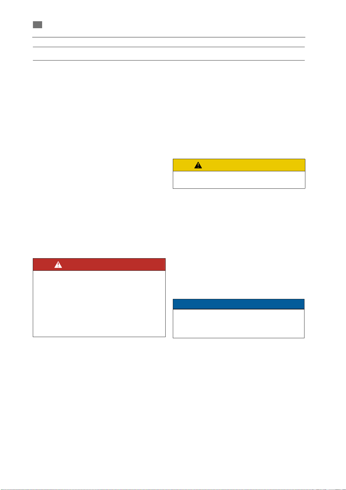
DANGER
CAUTION
NOTE
Installation
This chapter contains a description of the prerequisites for trouble-free operation of the system, as well
as instructions for setting up, starting up and transporting the device.
Requirements
To guarantee a faultless operation of the device the
following requirements have to be met.
Installation site
The installation site has to meet the following
requirements:
• The device has to be installed in a room as dry
and dust-free as possible.
• Do not expose the device to direct sunlight.
• It is recommended to set up the device so that,
if needed (cleaning the grid of the heat
exchanger, checking the coolant water level),
the two sides and the back of the device are
easily accessible.
Ambient conditions
• Temperature
Operation Ambient temperature
- Full load: max. 35°C
- Partail load: max. 40°C
Storage If the device contains cooling
water do not store or transport it
below 3°C (frost risk).
Never add antifreeze solution to
deionised cooling water!
• Humidity
Max. 85 % rel. - non-condensing
• Altitude
Max. 2500 mNN
Connecting load
The device can be used with the following electrical
connection values:
When choosing the installation site
take into consideration that for
servicing a suitable limitation of the
laser area is possible (see the regulations about accident prevention for
laser radiation BGV B2 or equivalent
national or international regulations
(e.g. EC Directive 60825 or IEC Publication 825).
• 230 V ~/50 Hz 13 A single phase
• 110 V ~/60 Hz 16 A single phase
The device is manufactured according to DIN EN
61010, protection class 1 and is only to be
connected to grounded power sources (power
sockets with protective contacts).
86076 DB-en/03 355.00032
24
Page 28
en
Installation
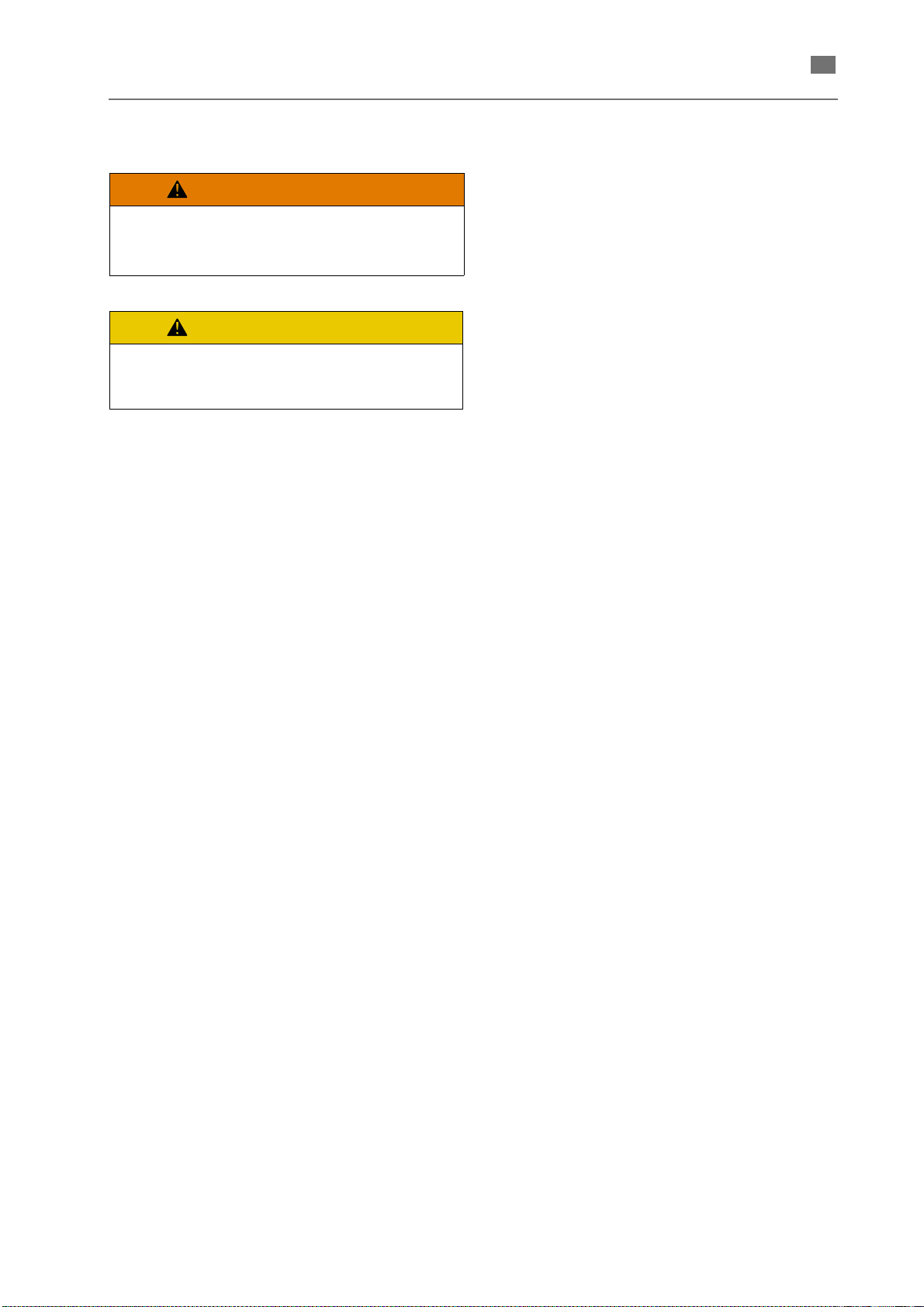
WARNING
CAUTION
High weight!
At least two people are needed to
carry the device.
Make sure that the table has a load
bearing capacity of > 60 kg when
setting up the LaserStar T Plus.
Unpacking
The laser device has been tested thoroughly before
shipping and has been delivered in faultless
condition. Check the packaging for transport
damages - if possible - before unpacking.
1. Take the device - if possible unpacked - to the
final installation site.
2. Leave the device in its packaging long enough
to allow it to acclimatize to its new environment
and prevent the formation of condensation.
3. Carefully remove the packaging if any.
4. Check the delivered parts for possible damage
during transport.
5. Check to see if the delivery is complete.
English ⋅ LaserStar T Plus
Basic Equipment
The standard parts of delivery are listed in the
following:
• Complete welding Laserstar T Plus
• Two keys for the key switch
• Microscope
• Retaining ring for the microscope
• 3 m protective gas hose
• Digital pedal switch, double-stage
• 2 Power supply cable (EU and USA/Japan)
• Fill tube with funnel
• Adjusting aid
• Adapter connection Argon
• Adapter for Ventus
• 10 liters of deionised water
• Documentation, consisting of:
• Instruction manual
• EU declaration of conformity
• Parameter table
86076 DB-en/03 355.00032
25
Page 29
English ⋅ LaserStar T Plus
en
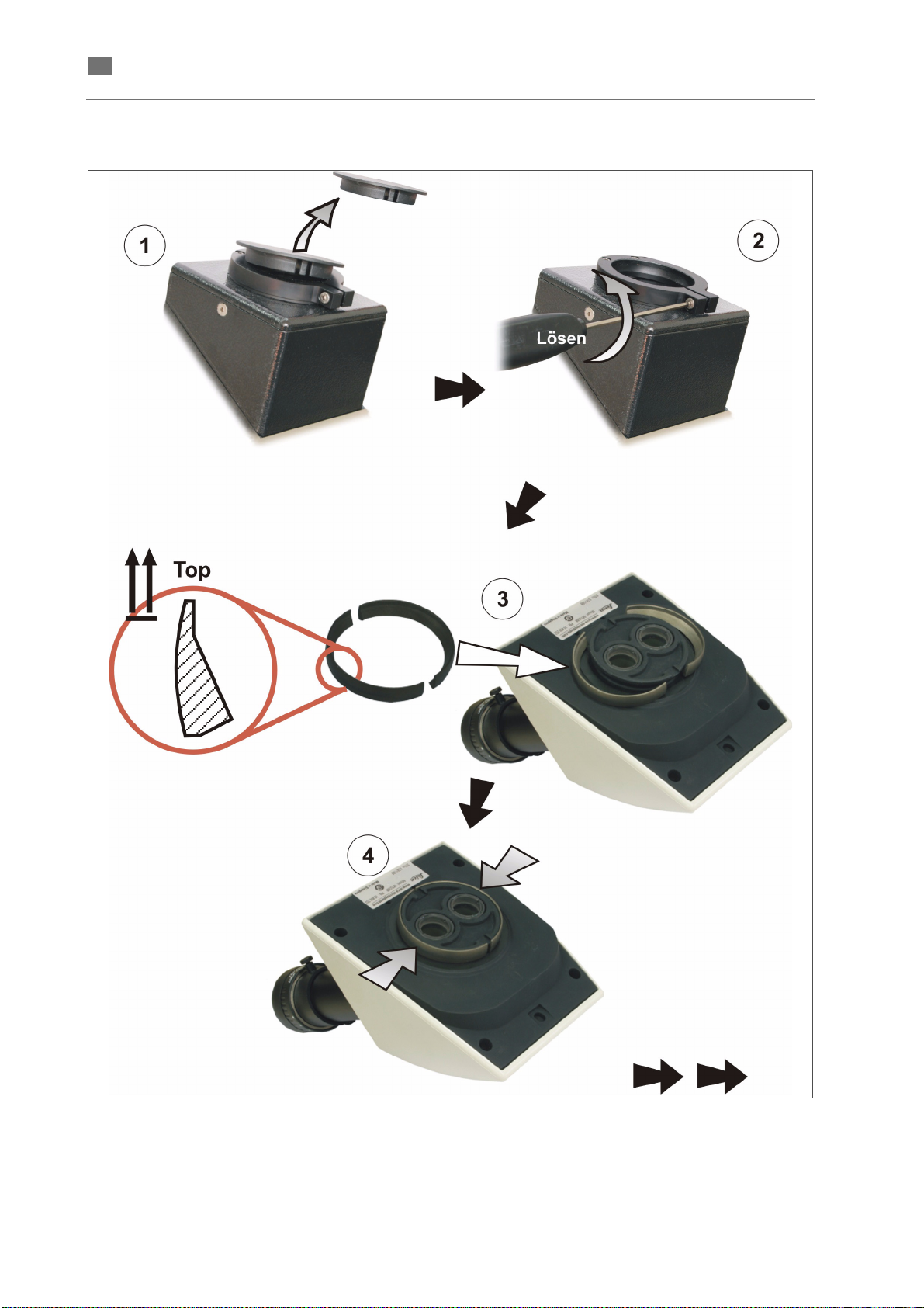
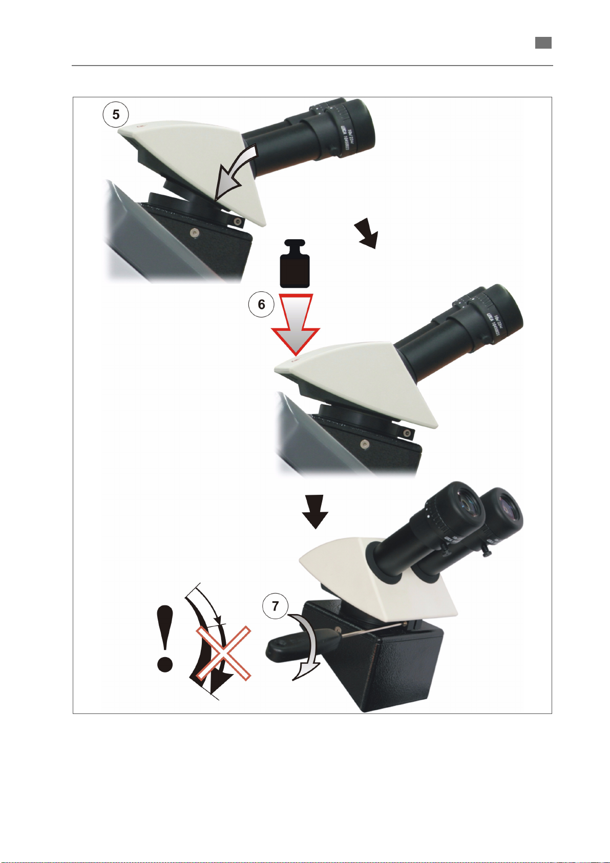
Mounting the stereo microscope
Fig. 22 Mounting the stereo mikroscope, Part1
86076 DB-en/03 355.00032
26
Page 30
English ⋅ LaserStar T Plus
en
Fig. 23 Mounting the stereo mikroscope, Part 2
86076 DB-en/03 355.00032
The adjustment of the stereo microscope is
described in the section
→ ADJUSTING THE
STEREO MICROSCOPE.
27
Page 31
English ⋅ LaserStar T Plus
en
NOTE
Filling up and connecting
For damages to persons or property caused by
improper connection of the device, warranty
responsibility claims void.
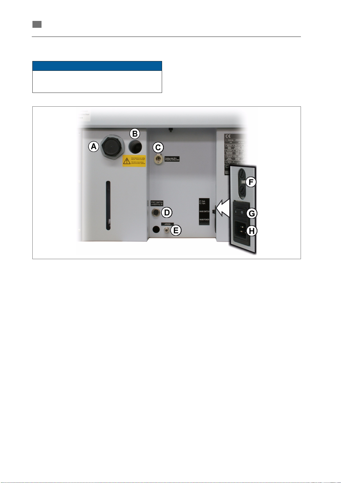
Connections
The connections are on the rear side of the device.
Fig. 24 Connection field on the back
(A) Water filter
(
→ REPLACING THE WATER FILTER)
(B) Hose connection for optional external extraction and filter unit
(C) Cooling water tank Filler neck for deionized cooling water
→ CHECKING/REFILLING THE COOLANT)
(
(D) FOOT SWITCH
LASERPULSE
(E) ARGON Inert gas supply (Argon)
(F) F1 16A
F2 16A
(G)+(H) MAIN POWER Power input
Inert gas
For the inert gas supply, the device is equipped with
a hose fitting for compressed air lines with a crosssection of 3 mm.
The maximum permitted working pressure is 8 bar
(1 bar is recommended).
Connector for pedal switch (pulse release, inert gas and
extraction fan)
Micro fuses
Cooling water
The water tank has to be filled up with deionised
water before setting the device into operation for the
first time. The procedure is described in the section
→ CHECKING/REFILLING THE COOLANT.
86076 DB-en/03 355.00032
28
Page 32
en
First putting into operation
NOTE
WARNING
English ⋅ LaserStar T Plus
After properly having finished all activities described
in the section
switch on the device as explained in the section
TURNING ON THE UNIT.
→ FILLING UP AND CONNECTING
Adjusting the stereo microscope
Adjusting the crosshair and focal plane
To achieve precise and reproducible welding
results it is necessary to adjust the stereo microscope to the individual visual acuity of the
operator. If the stereo microscope is not adjusted
correctly the workpiece can be recognized
exactly even if it is not in the focal plane of the
laser.
Procedure:
1. Turn on the system (only turn the main switch
to the "I" position).
2. Put a sample item (e. g. a steel plate) on a lab
jack in the visual field of the stereo microscope
so that it appears sharp (together with the
crosshair) seen through the right eyepiece.
If necessary, turn the right adjustment ring so
that the item appears sharp through the right
eyepiece.
3. Fix the sample item in this position.
4. Look with the left eye through the left eye piece
and turn the left adjustment ring so that the
item also appears sharp through the left eyepiece.
5. Adjust the distance of the two eyepieces so
that both visual fields (that appear bright) of
both eyepieces completely overlap each other,
i. e. while observing the test item with relaxed
eyes one single round visual field appears
without a black border on either its inside or
outside edge.
After this setting, the test object must appear equally
sharp in the right and left eyepiece, and the crosshairs must also be sharply discernable.
If the self-test has been finished without an error
message, the device is ready for operation.
Centering the crosshair/welding point
Risk of burning your fingers!
If the crosshair is not properly adjusted
there is a risk of burning your fingers.
If the position of the welding point on the workpiece
does not correspond to the position of the crosshair,
you have to adjust the crosshairs.
Procedure:
1. Ensure that the microscope is adjusted ideally
for your eyes (
CROSSHAIR AND FOCAL PLANE).
2. Place a steel plate on a workpiece holder (a
lab jack, for example), and adjust the height of
the steel part so that its surface appears in the
sharpest possible focus (by turning the adjusting screw on the lab jack, for example).
3. Set a voltage of approximately 215 V at a
pulse duration of 1.2 ms (
THE LASER PARAMETERS IN THE MAIN
MENU).
4. Look for a free surface on the steel part, do
not touch it anymore, and trigger a single
laser pulse.
5. Check the positions of the welding point
(SPOT) and crosshair.
6. If the crosshair is not exactly in the center of
the welding point, you have to adjust the position of the crosshair. Proceed as follows:
7. Use an Allen key (3 mm) to loosen the screw
under the microscope until the microscope can
be moved.
→ section ADJUSTING THE
→ section SETTING
86076 DB-en/03 355.00032
29
Page 33
English ⋅ LaserStar T Plus
en
WARNING
CAUTION
CAUTION
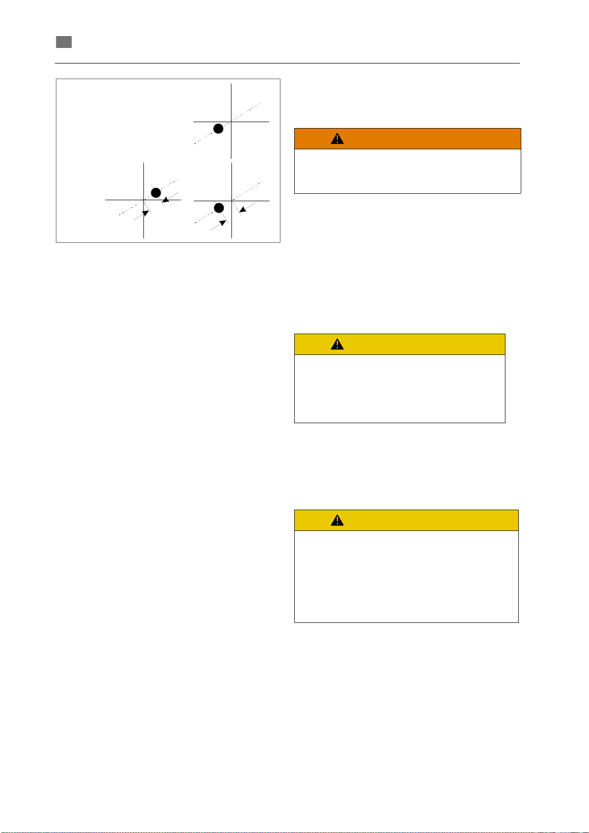
Fig. 25 Centering the crosshair
8. Center the crosshair by tilting the stereomicroscope toward the center of the welding point,
and tighten the Allen screw again until it is
secure. When you tighten the Allen screw, the
crosshair moves away from the center of the
welding point a little.
9. Loosen the screw under the microscope again,
and adjust the position of the crosshair so that
it is positioned the same distance away on the
opposite side of the welding point, and then tighten the Allen screw again until it is secure.
10. You may have to repeat this step several times
until the crosshair is positioned precisely
enough on the center of the welding point.
Ascertaining the real maximum power
If the system is connected to a mains supply of
110 V, it is recommended to perform a PSU test in
order to ascertain the real maximum power that can
be achieved with the current system configuration
(for details see PSU-Test in the section SERVICE
MENU ENGINEER, Engineer level/page 2).
Disassembling (preparation for transport)
High weight!
At least two people are needed to carry
the device.
To prepare the device for transport over minor
distances you only have to unplug the power supply,
the pedal switch and, if necessary, the inert gas
supply. The deionised water can be left in the tank.
It is recommended to drain the deionised water in
case the device should be stored or transported
over longer distances (transport by truck;
REPLACING THE WATER FILTER AND THE DI
WATER).
Danger of frost!
Do not store or transport the
device at a temperature below 3°C
if the cooling water remains in the
tank
If you are storing or transporting the device at a
temperature below 3°C or if the device is not used
for more than one month, additionally the excitation
unit in the laser head has to be opened and dried
out.
The usage of unsuitable materials for
drying out the optical components can
cause irreparable damages to
property.
Even tissues and clothes that seem to
be smooth can scratch optically
polished surfaces!
→ section
30
86076 DB-en/03 355.00032
Page 34
en
Operation
WARNING
WARNING
English ⋅ LaserStar T Plus
General instructions
The following sections describe how to handle the
unit. The symbols and fonts used in the description
are explained in the section
If smoke or gases are emitted when
working with the laser, you must not
continue working with a defective
exhauster.
There is a risk of hazardous gases
escaping from the working chamber.
Moreover optical components might
be polluted and irreparably damaged.
→ CONVENTIONS.
Turning on the unit
Workplace
The device is designed so that the operator can
easily reach all the necessary operating elements
while seated, provided that the device is placed on
a suitable table.
Burn hazard!
Before using the device, find a sitting
position that allows you to work in a
relaxed manner. In particular, the
freely-moving footswitch should be
placed in a suitable position to prevent
laser pulses from being unintentionally
triggered.
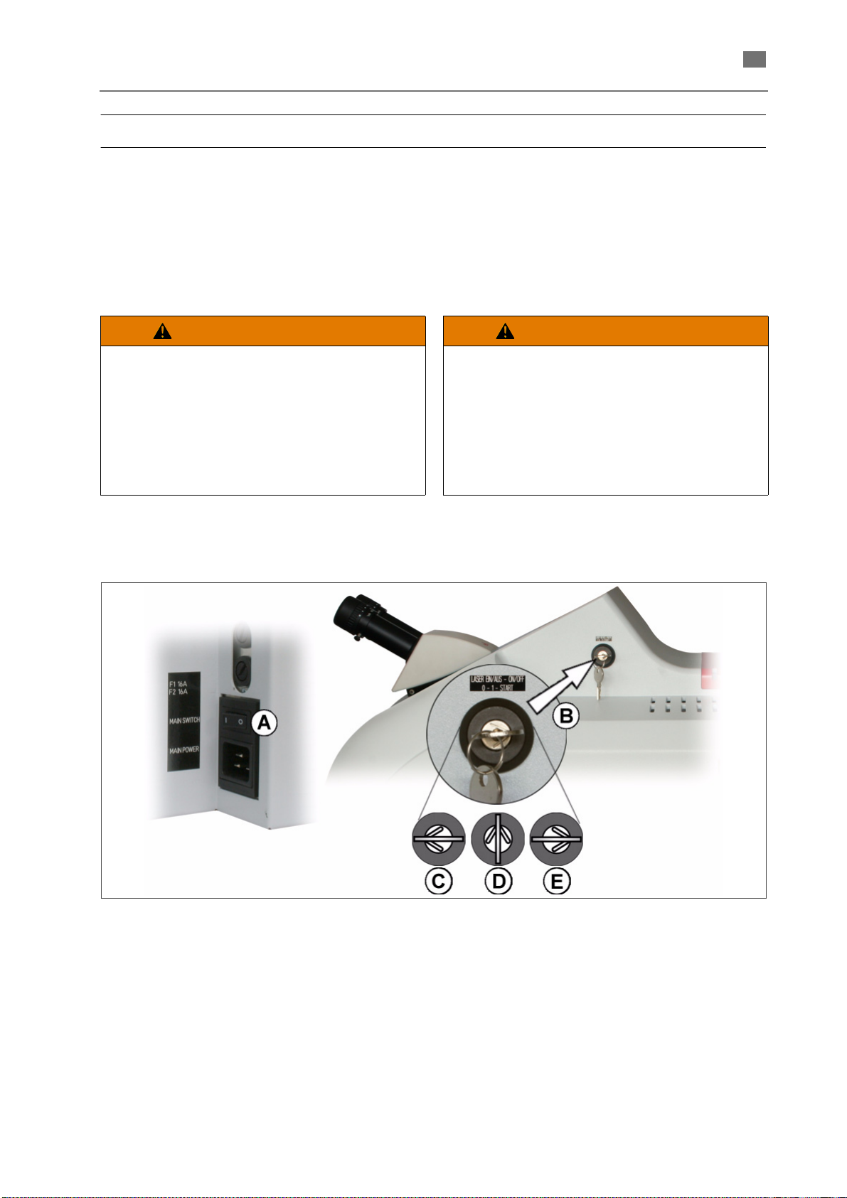
Fig. 26 Main switch and key switch
1. Make sure that the LASER key switch (B) is in
"0" position ((C) in Fig. 26).
2. Set the main switch (A) (on the back) to the "I"
position.
3. Turn the LASER key switch (B) to the middle
position (D).
The pump of the cooling system starts.
86076 DB-en/03 355.00032
4. Wait for about 1 second (until the supply voltages are ready).
5. Temporarily turn LASER key switch (B) into
START position (E), and than release back to
(D) position.
The laser lamp power supply is switched on
and the flash lamp is ignited.
31
Page 35
English ⋅ LaserStar T Plus
en
NOTE
DANGER
DANGER
Repeatedly turning the unit on and off causes a
temperature-related delay of the laser firing since
the energy saved in the laser must be reduced
each time via resistors.
This delay can last up to several minutes.
Wait for at least two minutes before turning the
unit back on.
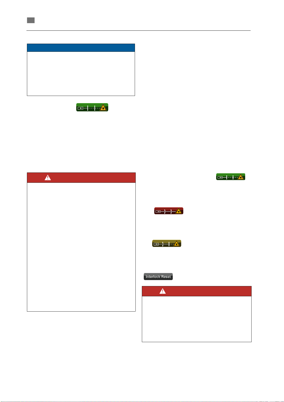
As soon as the symbol appears on
the display, the laser is ready for operation.
6. Check the operation of the safety installations
(
→ section CHECK SAFETY EQUIPMENT)
Check safety equipment
Safety information
Burning of eyes or skin
Check the condition of the laser
protective glass and the function of
the safety switches of the working
chamber door before the start of
each shift.
If the laser protective glass is
damaged (see following section) or if
the above mentioned safety switch
does not function properly, there is a
danger that a hazardous laser
radiation will exit the working
chamber.
In the cited cases, immediately turn
off the device and notify the responsible service department.
If you suspect that you have been
burned, especially your eyes,
immediately notify the laser safety
supervisor or the safety expert and
consult a doctor if necessary.
Visual inspection of the laser protective
window
The laser protective window should not have any
scratches, fractures, chips, cracks or discoloration.
If the protective laser window becomes defective, it
needs to be covered and immediately exchanged
with an intact window.
Make sure that the laser protective window is firmly
seated in the frame.
The laser protective window may only be cleaned
with clean water with added commercially available
dishwashing cleaning agent. Never use alcohol,
gas, acetone or similar solvents or hard or sharpedged objects.
Function test of the safety switch of the
working chamber door
Procedure
1. Make sure that the working chamber door is
completely closed and the Laser key is in 1
position (middle position).
The shutter status display
(on the touch screen in the main menu) is
green; the shutter is not released.
2. Touch the shutter status display.
The shutter status display switches to red
;the shutter is released, and
all safety circuits are closed.
3.
Open the working chamber door.
The shutter is closed immediately and the
shutter status display changes to
when the working chamber
door is open even slightly.
If you open the working chamber door too slow (so
that the debounce time is exceeded) an interlock is
triggered and the shutter status display switches to
.
Burning of eyes or skin!
If the shutter is not closed as
described above, uncontrolled laser
radiation may be emitted.
In this case, immediately shut off the
device and notify the responsible
service.
32
86076 DB-en/03 355.00032
Page 36
en
Function test of the EMERGENCY STOP button
1. Make sure that the laser has not been operated for a few minutes before starting the test
(or only at a very low output). Otherwise, there
is the danger that the laser lamp may overheat.
Setting / managing laser parameters
English ⋅ LaserStar T Plus
2. Press the EMERGENCY STOP button to the
left of the stereo microscope.
Only the laser power supply is turned off,
the water pump is still running.
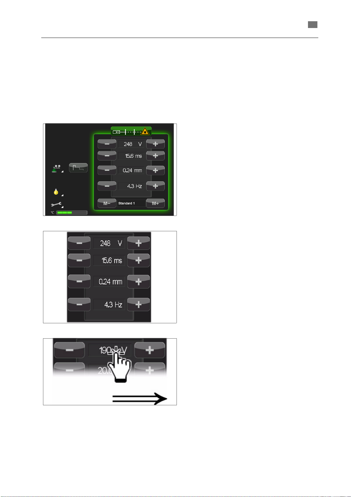
Use the [ - ] und [ + ] buttons to change the laser
parameters step by step (in the last indicated digit)
within the permitted limits.
The set parameters are used for the following
welding processes and can be saved for later uses
(
→ SAVING LASER PARAMETERS).
Fig. 27 Main menu
Fig. 28 Exceedance of parameter values
The current (new set) parameter values are
indicated between the buttons. Exceeded
parameter values are indicated in red characters in
the following cases:
• permanently red, if a permitted limit for the
parameter has been reached or exceeded;
• temporarily red if the laser is short term inoperable due to a change of the respective parameter.
1. Touch any of the laser parameter values to
open the
→ ALPHANUMERIC INPUT WIN-
DOW for the input of a new value for the
respective parameter.
Fig. 29 Opening the input window
86076 DB-en/03 355.00032
33
Page 37
English ⋅ LaserStar T Plus
en
NOTE
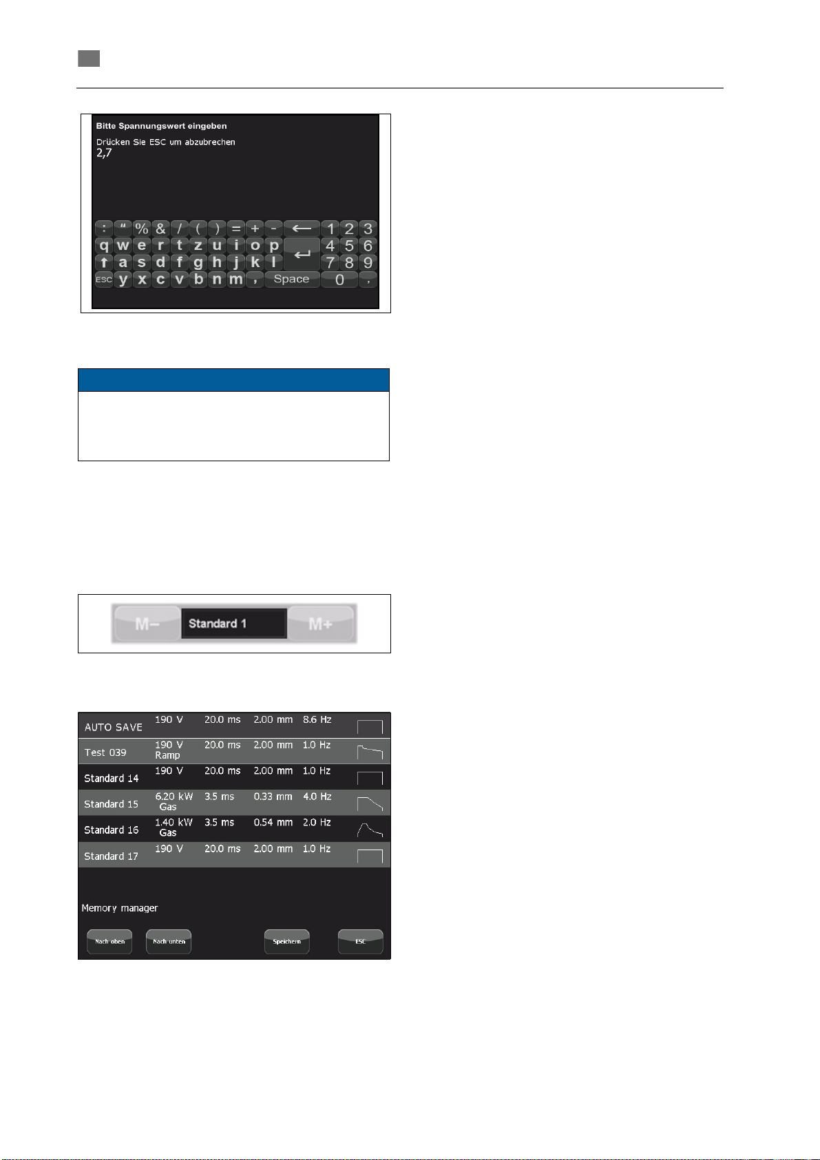
Fig. 30 Alphanumericinput window
If you have entered a value exceeding the
permitted limits and confirmed it with [ ↵ ] the
max. permitted value is taken and indicated in the
main menu with red numerals.
2. Enter the desired parameter value via the
touchscreen keyboard (details
MERIC INPUT WINDOW) and confirm the
input with [ ↵ ].
The input window is closed and the entered value
is indicated in the main menu.
→ ALPHANU-
Saving laser parameters (memory manager)
The currently set laser parameters (including the
selected pulse shape, inert gas and MicroWeld™
settings) can be saved for later uses.
1. Touch the storage space name to open the
memory manager:
Fig. 31 Example for laser parameter
[Up] / [Down]
2. Scroll with these buttons until the desired storage space is indicated in the list.
[Save]
3. Touch the [ Save ] button.
The prompt Chose a memory position to
save is indicated below the list and the text of
the [ Save ] button changes to [ Save to … ].
4. Touch the line in the list where the parameter
is to saved.
The → ALPHANUMERIC INPUT WIN-
DOW is opened with the prompt Please enter
program name.
[ Save in ]
5. Enter a name for the storage space (max.
length 16 characters) and confirm with [ ↵ ].
The laser parameters set in the main menu
are stored under selected memory space. The
previously saved laser parameters are overwritten without any warning.
The memory manager is closed; return to
the main menu.
86076 DB-en/03 355.00032
34
Page 38
en
AUTO SAVE
The current parameter setting in the main menu are
automatically saved in this memory space as soon
as a parameter set is loaded from the memory (with
the buttons [ M– ] or [ M+ ] in the main menu or via
the memory manager) or if the device is turned off.
Loading laser parameters (memory manager)
You can load a parameter set for welding (including
the selected pulse shape, inert gas and Micro-
TM
Weld
settings) from the saved laser parameters.
1. Touch the storage space name to open the
memory manager:
[Up] / [Down]
2. Scroll with these buttons until the desired storage space is indicated in the list.
3. Touch the line in the list where the parameters
to be loaded into the main menu are stored.
The memory manager is closed; return to
the main menu.
English ⋅ LaserStar T Plus
Alternatively to the direct selection described above
you can load the previous or next parameter set
(related to the currently loaded parameter set) using
the [ M– ] or [ M+ ] buttons in the main menu.
86076 DB-en/03 355.00032
35
Page 39
English ⋅ LaserStar T Plus
en
Retrieving and editing pulse shapes (pulse shape editor)
Basics
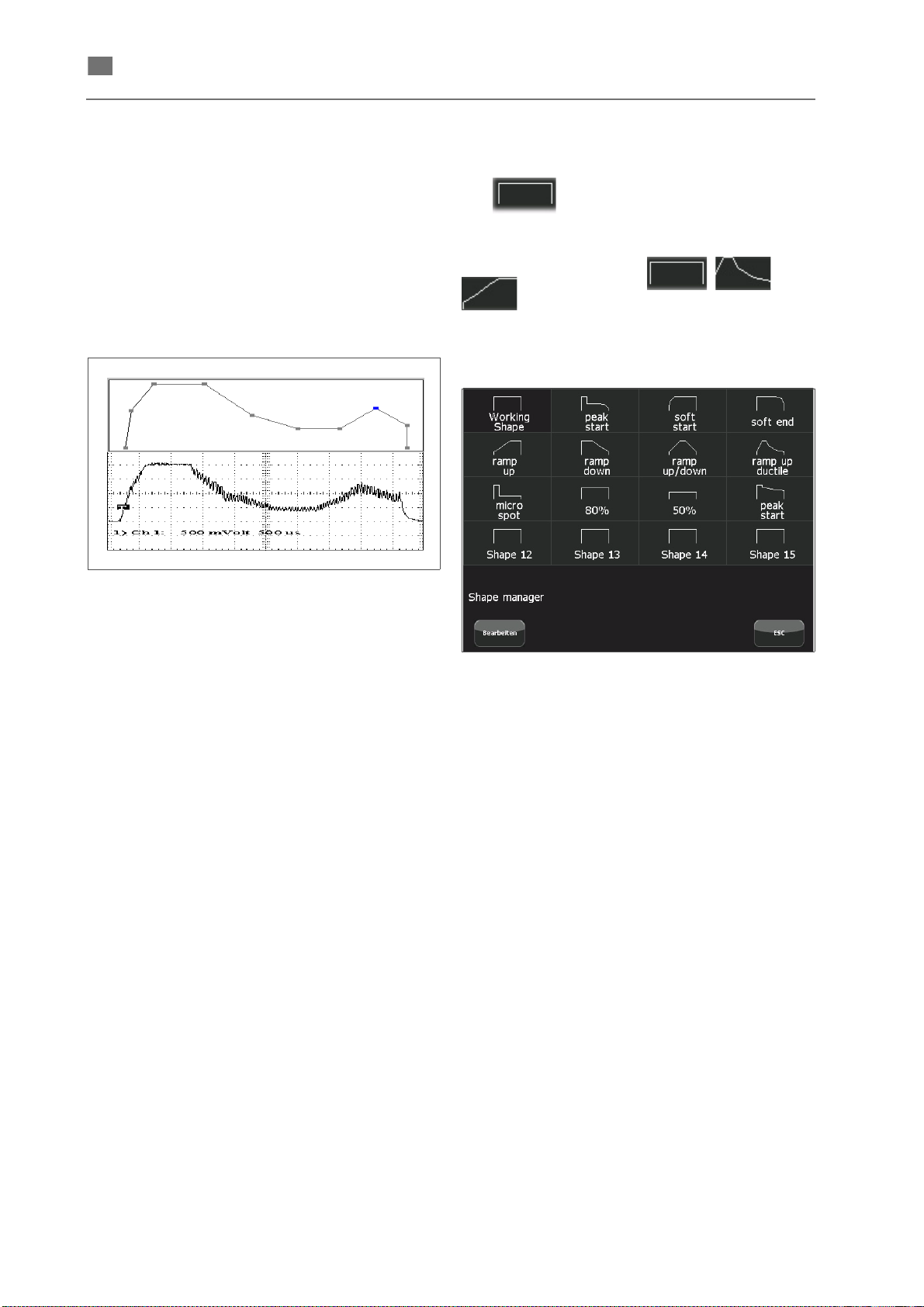
The shape of the laser pulse (i. e., the time base of
the intensity of the laser beam) has an essential
influence on the behavior of the material and thus on
the results of the welding. Processing metal you
need e. g. a temporary high pulse energy due to the
high reflection coefficient. If you do not decrease
this pulse energy in time the liquefied metal starts
cooking and splashing violently.
Fig. 32 Adapting the pulse energy
Pulse shape editor (Shape manager)
The button in the main menu opens the
pulse shape editor (see the following figure).
The symbol in the button shows the currently
selected pulse shape (e. g.
etc.).
The window shows the name and shapes of all
available pulse shapes.
, ,
The welding laser provides the possibility of
adapting the pulse shape, with graphic support, to
the specific requirements of the weld and storing the
various pulse shapes for use at a later date.
The figure above shows a (theoretical) pulse shape
created in the pulse editor in comparison with the
actually measured laser power.
Fig. 33 Example of pulse shapes
Select pulse shape
Touch the desired pulse shape.
The pulse shape is loaded to the main menu and
the pulse shape editor is closed.
Edit pulse shape
1. Open the pulse shape editor as described
above.
[Edit]
2. Touch the [ Edit ] button to activate the edit
mode.
The prompt Chose a shape to edit is indica-
ted beneath the pulse shape table.
3. Touch the desired pulse shape.
The selected pulse shape is loaded to the
editor (see the following figure).
86076 DB-en/03 355.00032
36
Page 40
en
Fig. 34 Editing the pulse shape
NOTE
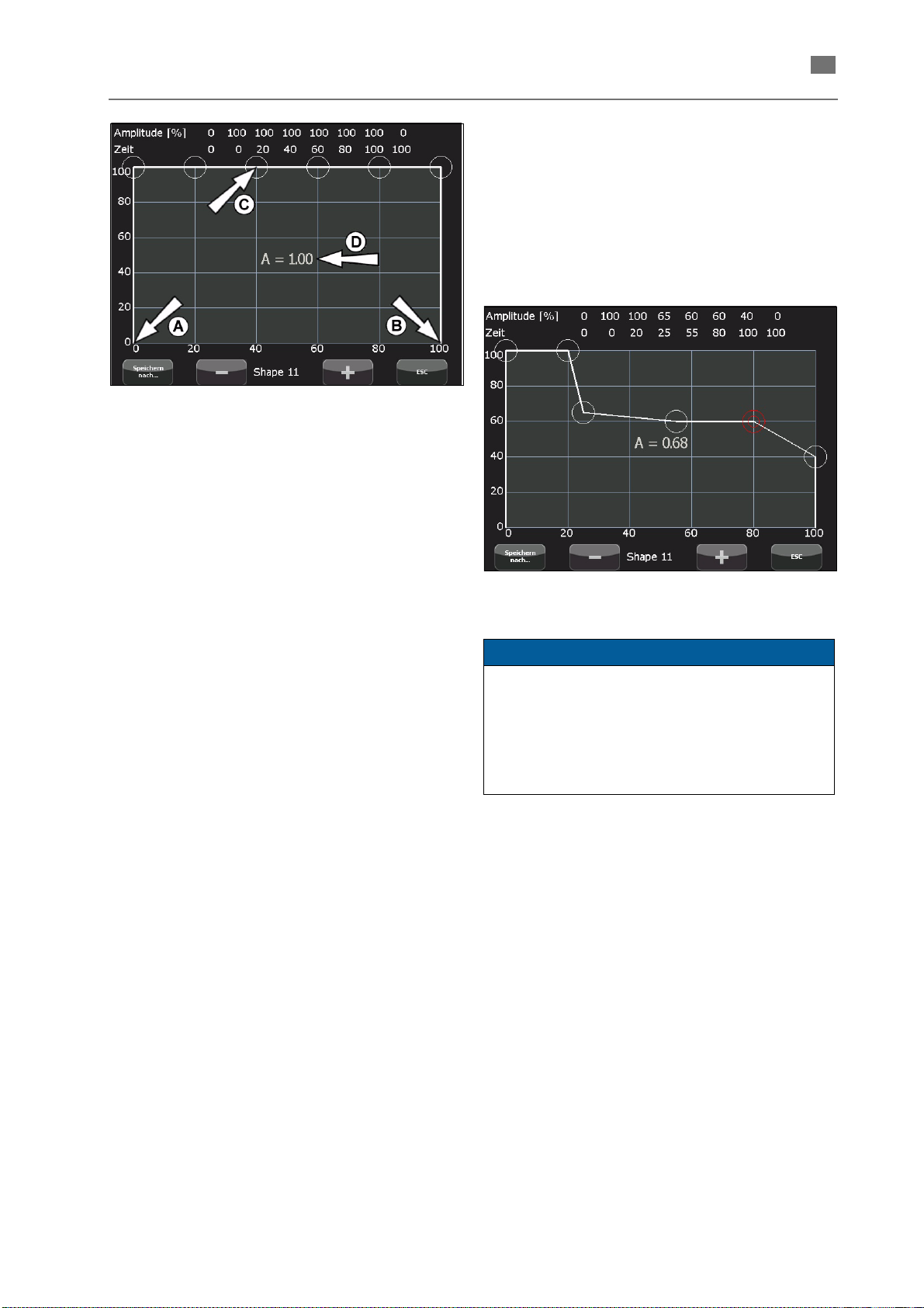
The pulse shape is determined by 8 nodes and
indicated in a time amplitude diagram (x-axis: time,
y-axis: amplitude).
The starting point ((A) in the figure above) and the
end point (B) cannot be changed.
The remaining nodes (example (C)) are marked by
circles and can be changed at the touchscreen.
Amplitude [ % ] / Time
The numerical values of the time and amplitude
coordinates of the nodes are displayed on the top
edge of the graphic editor.
A = 1.00
The relative pulse energy (= area of the pulse
shape) is indicated in the center of the diagram ((D)
in Fig. 34). The value 1.00 corresponds to the max.
energy (in Joule) of the rectangular pulse shown
above.
Shape 11
The current name of the pulse shape is indicated
below the pulse form graphic.
English ⋅ LaserStar T Plus
Change pulse shape
1. To move a node, touch the respective node,
drag it to the desired position and release it.
Two concentrical red circles mark the cur-
rently activated node (see Fig. 35).
The connecting lines to the neighboring
nodes follow the movement of your finger or
pointer on the touchscreen.
Fig. 35 Changing the pulse shape
Restrictions when moving nodes.
• The two outer nodes can only be moved up
and down.
• The other nodes cannot be moved horizon-
tally beyond the neighboring nodes.
• The step interval is 5 %.
Change pulse shape names
1. Touch the pulse shape name below the pulse
shape graphic.
The → ALPHANUMERIC INPUT WINDOW
is opened with the prompt Please enter shape
name.
2. Enter the desired name (max. 16 characters)
and confirm with [ ↵ ].
The alphanumeric input window is closed
and the new name is displayed in the pulse
shape editor.
86076 DB-en/03 355.00032
37
Page 41
English ⋅ LaserStar T Plus
en
Save pulse shape
1. Touch the [ Save to ] button (in the pulse
shape editor).
The pulse shape editor window is closed
and the prompt Save to... is indicated in the
pulse shape manager (below the pulse shape
table).
2. Touch the line in the pulse shape table (of the
pulse shape manager) where the currently edited pulse shape is to be stored.
The pulse shape manager is closed and the
new pulse shape is loaded to the main menu.
ECO-Modus settings
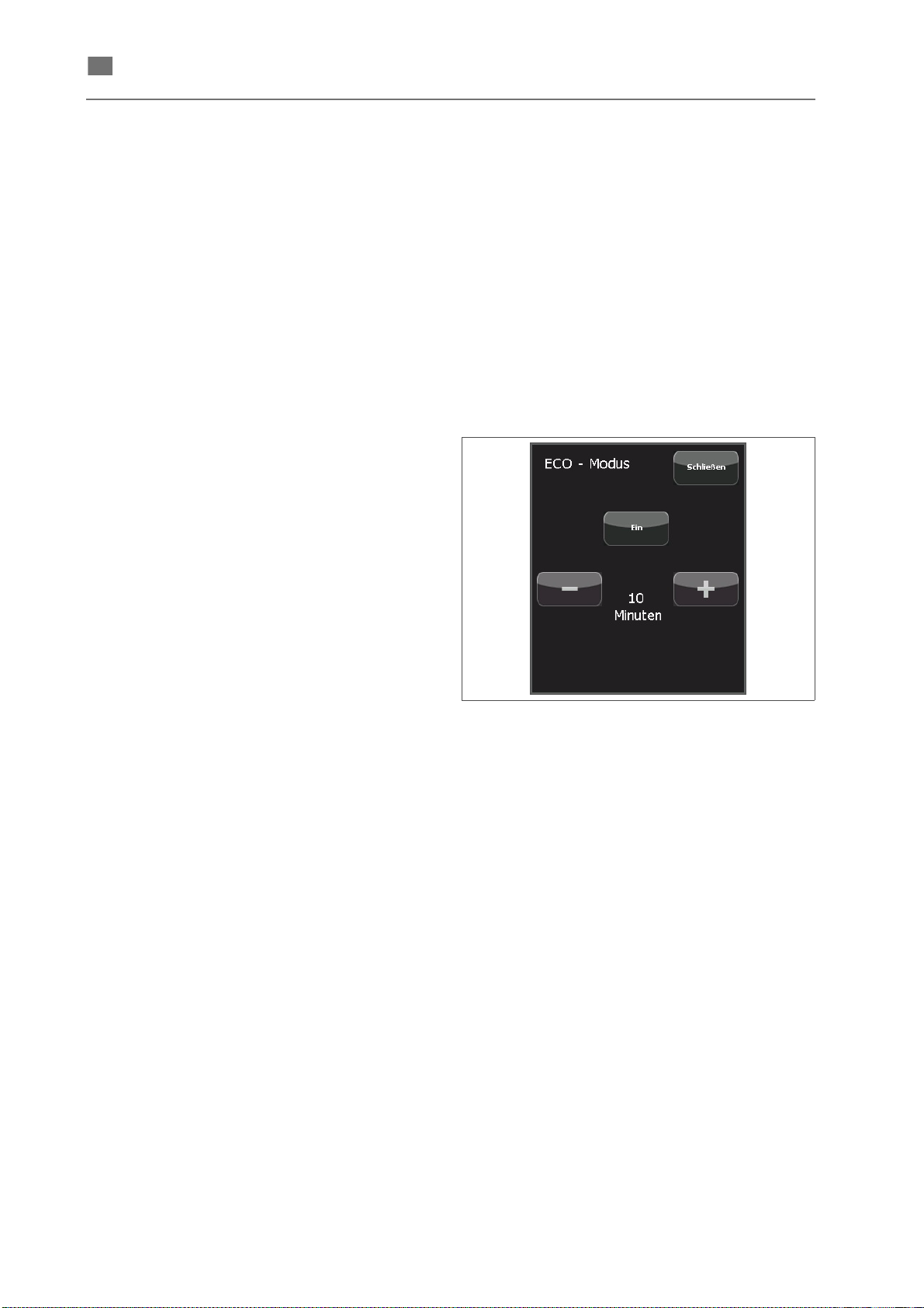
Basics
The activated ECO-Modus systematically turns off
not required system components according to the
user-defined settings (see below).
The ECO-Modus guarantees fast restart in less than
1 second.
Any system operation (e. g. touching the screen)
finishes the ECO-Modus.
[ Change ]
This button in the
the following dialog.
→ SERVICE MENU USER opens
Fig. 36 Setting the ECO-Modus
[Close]
The window is closed, and the made settings are
kept even if the system is shut off.
[On]([Off])
This button activates / deactivates the ECO-Modus
with a set waiting time. The button text shows the
current status.
Minutes
Display of the set waiting time for switching off the
system components.
Touch the [ – ]/[ + ] buttons to change the waiting
time (in minutes).
86076 DB-en/03 355.00032
38
Page 42
English ⋅ LaserStar T Plus
en
Switching inert gas on/off
This button in the main menu activates / deactivates
the inert gas supply.
If activated (button without the symbol ) the inert
gas supply can be switched on with the foot switch.
Setting workpiece illumination
This button in the main menu opens the following
dialog for setting of the workpiece illumination.
Fig. 37 Setting the brightness of the ring lamp
[Close]
The window is closed, and the setting changes are
kept even if the system is shut off.
Ring lamp
Display of the set brightness of the LED ring lamp.
Touch the [ – ] / [ + ] buttons to adapt the brightness
of the LED ring lamp.
Touch the [ On ] ([ Off ]) buttons to turn the LED ring
lamp on or off. The button text shows the current
status.
86076 DB-en/03 355.00032
39
Page 43
English ⋅ LaserStar T Plus
en
NOTE
Turning off the system
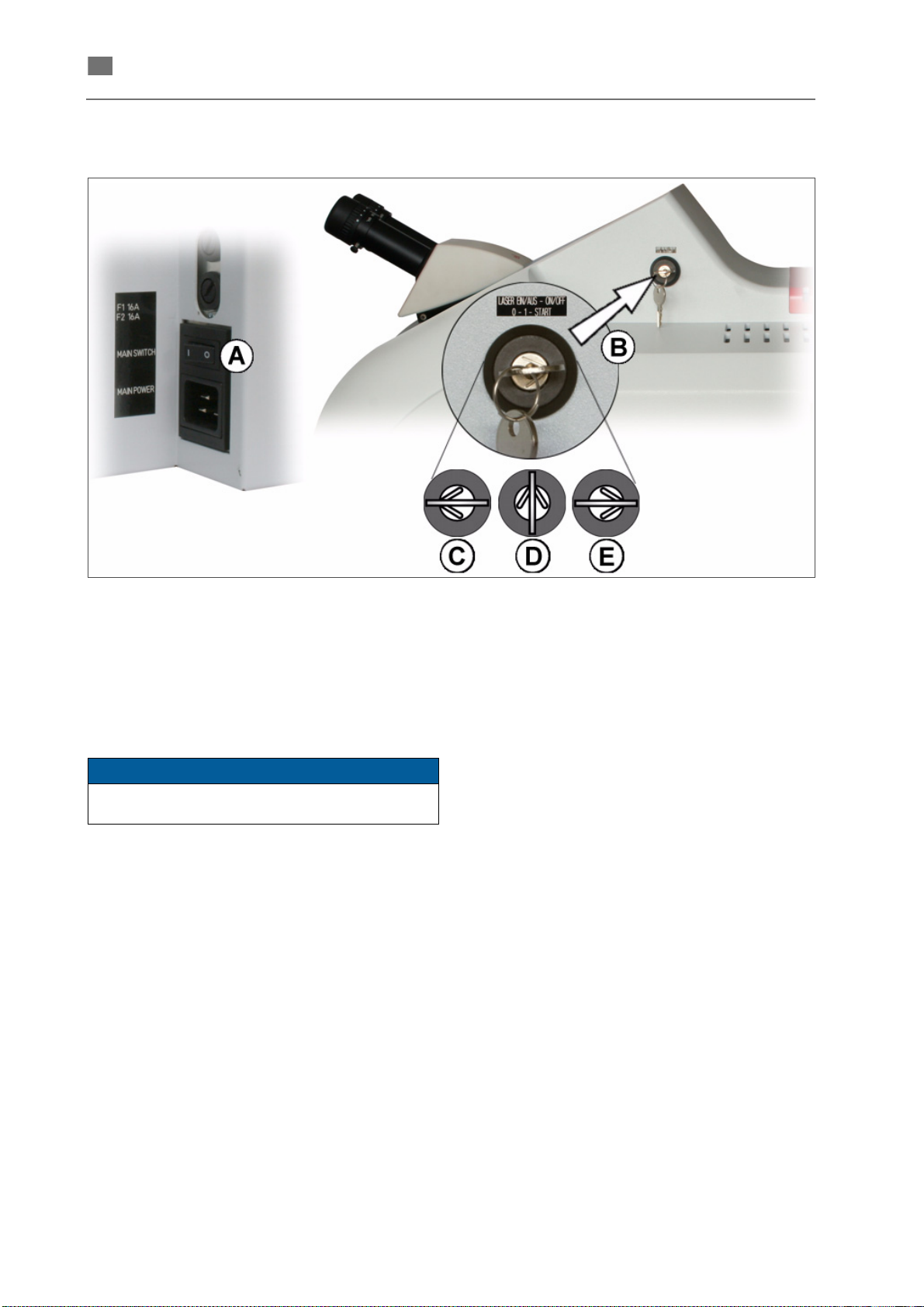
Fig. 38 Switches and Connector Panel
1. Save entries (such as laser parameters, pulse
shapes) that are not yet saved.
2. Turn the LASER key switch (B) to the "0" position (C).
Remove the key and store it in a location that is
only accessible to authorized persons.
3. Set the main switch (A) MAIN POWER to the
"0" position.
4. If applicable, close the valves for the inert gas
in the gas cylinder fittings.
86076 DB-en/03 355.00032
40
Page 44

English ⋅ LaserStar T Plus
en
NOTE
Faulty operations
This section describes common faulty operations of the laser system.
Error description Possible cause Remedy
The laser was not ignited. Temporarily turn the LASER key switch
1. Display:
immediately after turning on
into START position.
2. Expected laser power can not
be achieved.
Inappropriate parameter
settings
Log book
To ensure smooth and safe operation, it is highly
recommended to keep a log book for each
device.
In this log book, you should record all malfunctions and unusual events, as well as all servicing
and repair tasks.
It is also recommended to use the electronic log
function. This requires the following (
MENU ENGINEER):
• Ensure that date and time are set correctly.
• Reset the lamp pulse counter after having
replaced the lamp.
• Confirm the DI filter changes.
• Confirm the safety check.
Thus, these maintenance activities are
documented and the maintenance recommendations generated by the system are displayed in
sufficient time.
→ SERVICE
Temporarily disable all special
functions (e. g. burst) and test the laser
power.
Check and correct the current
parameter settings.
86076 DB-en/03 355.00032
41
Page 45

English ⋅ LaserStar T Plus
en
Dental instructions
Basic instructions
Planning the joint
The aim of every welding operation must be to join
the workpieces together such that they can
withstand the expected stress on a long-term basis.
"Circular deep penetration welding" has proven
effective in accomplishing this, especially in the
case of larger cross-sections. In this process the
workpieces are not welded together completely into
their inside, but circumferentially along their
connecting seam and as deep as possible (approx.
1 mm deep). To ensure that this joint is durable,
however, work must be carried out very meticulously:
The design of the denture must therefore be
planned in advance and modelled in wax appropriately. As a result, defects due to incorrect
selection of material, incorrect welding wire and
joints that are difficult to access are avoided.
Planning must also take into account the later
mechanical stress on the joint.
• The connecting seam of the workpieces must
be expanded somewhat (bevelling of the
edges) in order to gain some depth for the
seam.
• The workpieces must be welded at every point
of their joint, i.e. completely "all around".
• The spot welds must overlap sufficiently
(approx. 80%).
Joints can also be welded "through and through",
i.e. into the inside, which, however, can only be
achieved with careful preparation of the weld right
from the wax-up stage or by grinding to form a Vshaped extended joint or a double-V butt joint
through the use of wire as filler metal (see Fig. 41).
This applies in particular to smaller cross-sections,
such as clasps, bars and sublingual bars.
In cases where there is no room for preparation of a
seam by grinding to form a V butt joint and the
expected forces permit this, butt joints can be
welded on one side (notch type joint), such as in the
case of welding on an attachment backing plate
(extracoronal).
Larger distances should initially be bridged by
means of fit-in pieces of the same material. In this
way one reduces the necessary pulses to fill the gap
and avoids or reduces distortion.
86076 DB-en/03 355.00032
42
Page 46
en
Using welding wire
Often the job is to weld the workpieces through and
through into the inside. This is done by enlarging the
seam to the centre and filling with welded-in wire as
filler metal.
Recommended filler metals: see table on next page.
An alternative method is the above described
"circular deep penetration welding", which is
especially suitable for large cross-sections.
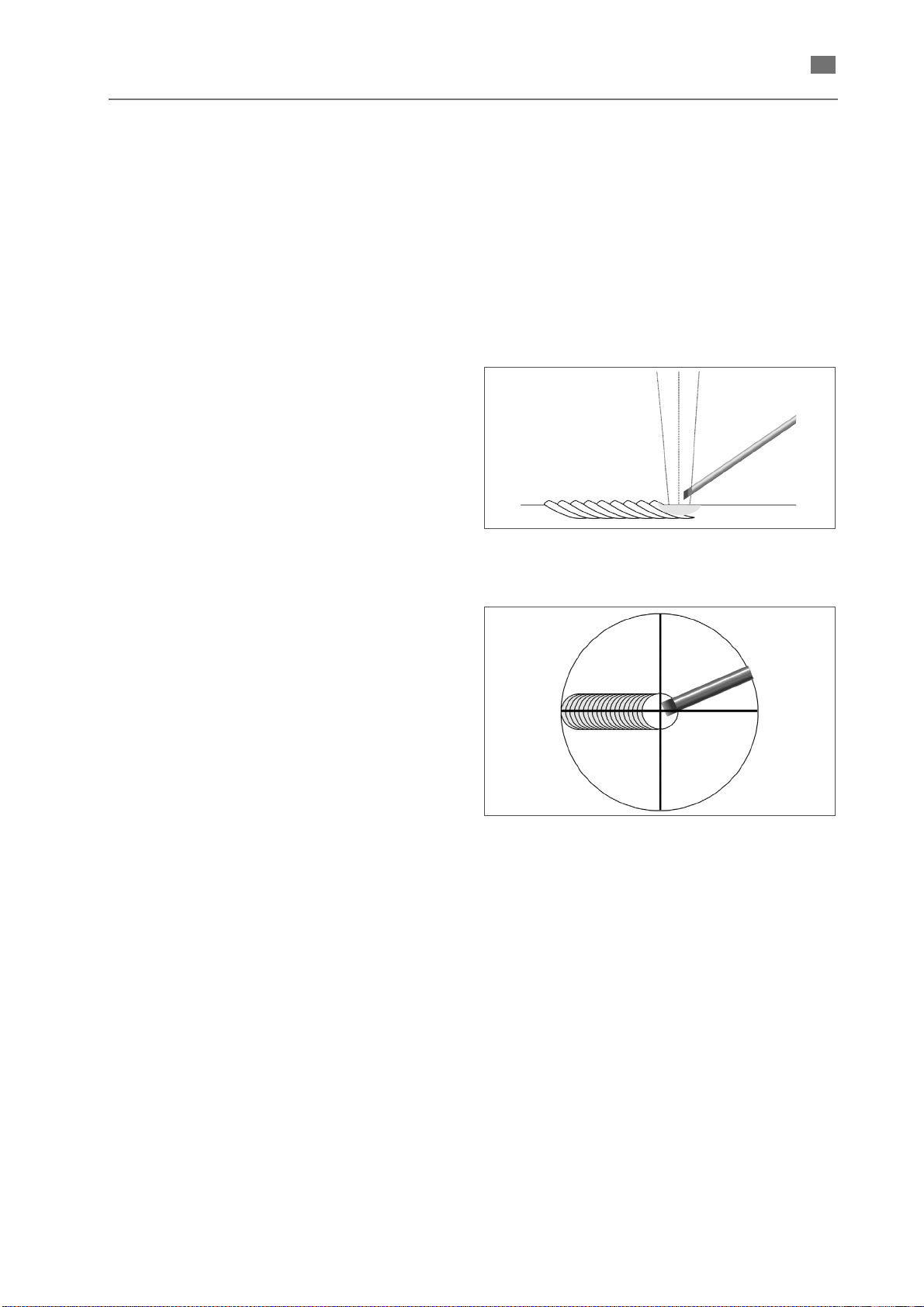
The welding wire is to be applied through the socalled melting bath method:
• Every laser pulse is to be directed such that
approx. 1/3 is aimed at the wire tip and approx.
2/3 at the metal surface so the metal dripping
from the wire strikes a molten surface
(Fig. 39).
• The spot welds should overlap by approx. 80%
so the centre of the previous spot is always
covered (Fig. 40).
• An example of welding parameters (the exact
values must be determined through tests)
Non-precious wire Wiroweld:
approx. 260 - 280 V, approx. 8 ms
Precious metal wire:
280 - 300 V, approx. 15 ms
English ⋅ LaserStar T Plus
Fig. 39 Melt welding wire and surface at the same
time
Fig. 40 Place spot welds so they overlap by approx.
80%
86076 DB-en/03 355.00032
43
Page 47

English ⋅ LaserStar T Plus
en
BEGO filler metals for laser welding
Alloy Recommended filler
metal
• High gold content, veneerable
Bio PontoStar XL Bio PontoStar XL wire 61167
Bio PontoStar Bio PontoStar wire 61157
PontoStar G PontoStar G wire 61150
PontoStar Ti PontoStar G wire 61150
PontoLloyd P PontoLloyd P wire 61154
• Reduced gold, veneerable
BegoCer G BegoCer G wire 61164 Bio PontoStar-/PontoStar G wire
BegoRex
BegoStar PontoStar G wire 61150 castings with precise fit
• Palladium base, veneerable
BegoPal 300 BegoPal 300 wire 61165 Bio PontoStar-/PontoStar G wire
BegoPal S
BegoPal PontoStar G wire 61150 castings with precise fit
BegoStar ECO BegoStar ECO wire 61171
Bio PontoStar wiret or 61157 weld in appropriately ground
} {
Bio PontoStar wire or 61157 weld in appropriately ground
} {
Order
No.
Alternative
• High gold content, LFC veneerable
Bio PlatinLloyd Bio PlatinLloyd wire 61161
PontoRex G PontoRex G wire 61151
PontoRex H PontoRex G wire 61151
PlatinLloyd KF PlatinLloyd KF wire 61158
Pontonorm Pontonorm wire 61172
• Reduced gold, LFC veneerable
AuroLloyd KF AuroLloyd KF wire 61153
BegoLloyd LFC AuroLloyd KF wire 61153
BegoStar LFC AuroLloyd KF wire 61153
ECO D‘OR ECO D‘OR wire 61170
• High gold content, not veneerable
InLloyd 100 InLloyd 100 wire 61163
PlatinLloyd 100 PlatinLloyd 100 wire 61152
PlatinLloyd M PlatinLloyd M wire 61155
• Reduced gold, not veneerable
BegoLloyd PF BegoLloyd PF wire 61156
86076 DB-en/03 355.00032
44
Page 48

English ⋅ LaserStar T Plus
en
• CoCrMo partial denture alloys
Wironium Plus “Wiroweld” CoCrMo wire 50005 50003
Wironium “Wiroweld” CoCrMo wire 50005 50003
Wironium extrahard
“Wiroweld” CoCrMo wire 50005 50003
Wironit LA “Wiroweld” CoCrMo wire 50005 50003
Wironit “Wiroweld” CoCrMo wire 50005 50003
Wironit extra-hard “Wiroweld” CoCrMo wire 50005 50003
• Non-precious alloys, veneerable
Wirobond 280 “Wiroweld” CoCrMo wire 50005 50003
Wirobond C “Wiroweld” CoCrMo wire 50005 50003
Wirobond SG “Wiroweld” CoCrMo wire 50005 50003
Wiron 99 “Wiroweld NC” NiCrMo wire 50006 “Wiroweld” CoCrMo wire
Wirocer Plus “Wiroweld NC” NiCrMo wire 50006 “Wiroweld” CoCrMo wire
• Non-precious alloys, not veneerable
Wirolloy “Wiroweld NC” NiCrMo wire 50006 “Wiroweld” CoCrMo wire
•Titanium
Titanium Pure titanium Gr. 2 wire 50008 direct butt joint possible
Material thickness: BEGO precious metal wires 0.35 mm, Wiroweld 0.35 and 0.5 mm, Wiroweld NC
0.35 mm, titanium wire 0.35 mm.
Important: If different alloys are welded together (e.g. combination technique), always use the nobler
material as the filler metal!
86076 DB-en/03 355.00032
45
Page 49

English ⋅ LaserStar T Plus
en
Pay attention to alloy composition
With some alloy combinations there are metallurgical processes in the weld area that may call the
strength into question:
• Partial denture alloys with a high proportion of
carbon are suitable as a laser filler metal only to
a restricted degree. In these cases welding is
successful with filler metal of BEGO's carbonfree non-precious Wiroweld welding wire on a
CoCrMo base.
Preparing surfaces
Blasting
The laser beam is reflected by polished metal
surfaces. The surfaces of the parts to be welded
must be kept matt so as to prevent energy losses
due to reflection (or to promote the energy effect
through increased absorption). For this reason
always prepare the welding surfaces by blasting
with Korox 50 or Korox 110. Alternative: blacken the
welding area with a felt-tip pen.
Build-up welding
If precious metal and non-precious metal are to be
joined, precious-metal welding wire can first be
applied to the non-precious surface in a thin layer
(so-called build-up welding). Here the drops fall from
the tip of the wire covering spot by spot, as
described above.
Inert gas
There are connecting sockets on the laser device for
inert gas (argon).
The processing chamber contains a movable inert
gas nozzle (for argon) at the end of a swan-neck
which can be set in any position near the workpiece.
In addition, there is a rigid nozzle for inert gas
between the LED ring lamp. It has a coupling and
can be dismantled if necessary.
To protect the weld against oxidation, it must be
constantly swept with argon inert gas (purity 4.6 =
99.996 to 5.0 = 99.999). Therefore, ensure that the
inert gas nozzle is always directed at the weld. In
this way vapour deposition on the optical components is avoided and a loss in power is prevented
effectively. The gas flow continues as long as the
foot switch is held down half way or more. The inert
gas can thus be used economically by means of the
foot switch.
The vapours produced during welding and the inert
gas are extracted and filtered continuously.
Selecting welding parameters correctly
The energy required for the respective welding job,
given by
• charging voltage (the energy rises with the voltage) and
• pulse time (the energy rises as the time increases),
• Focus (the energy increases as the focus
decreases),
• Pulse shape (the energy varies according to the
shape of the pulse)
depends on the geometry and composition of the
workpieces as well as the dimension of the filler
metal. The energy required to weld the workpieces
together increases with the thermal conductivity and
the reflectivity of the alloy.
The energy flow into the workpiece, i.e. the energy
density, is influenced by the presetting of the
welding parameters.
In general, the following applies for the different
materials:
Cobalt-chromium partial denture alloys
(CoCrMo), non-precious alloys (NiCrMo)
and in particular titanium require lower
levels of energy than precious metals or
alloys containing precious metals because
of their intensive absorption behaviour.
Select a lower voltage and/or shorter pulse
time for partial denture alloys, non-precious
alloys and titanium than for precious metals.
Important:
• You must always begin at a low power level, i.e.
low voltage and short discharge time, so as not
to damage the workpiece. This has to be checked in each case through a test at or outside
the weld.
• In the case of combinations of different types of
alloys, 2/3 of the weld spot must always be on
the material with the higher thermal conductivity, i.e. with combinations direct the laser beam
at the high-grade alloy.
86076 DB-en/03 355.00032
46
Page 50

English ⋅ LaserStar T Plus
en
Fix ("bond") on the model
Since the laser weld must be executed on all sides
with few exceptions and, moreover, the filler metal
wire is fed manually, first the workpieces to be joined
have to be tacked together with prepared welds in
the correct position such that they can be removed
for completion without stress.
Tacking can be carried out without filler metal by
means of several welding pulses on sections that
are not more than approx. 0.5 mm apart (if
necessary, the workpieces must be built up to this
distance). However, in most cases filler metal
should then be added before raising to maintain
adequate stability. If the gap is large, an interdental
contact point has to be welded on or a suitably large,
appropriately ground piece of alloy must be tacked
in with filler metal, prepared on both sides with a
single-V or double-V butt joint.
Notes:
• To protect the model, place a thin silver foil
under the welding point. It reflects the radiation
and prevents sulphur vapours that form during
the decomposition of plaster.
Avoiding stress
When the seam is filled with filler metal, the
workpiece is heated locally, which is inevitably
connected with stress. (For example, a rod can be
bent by bombarding it on one side with laser energy
because of only a few spot welds. Proficient dental
technicians can "appropriately shoot" "swinging
bridges" with targeted laser spot welds as long as
the deformation remains limited and runs vertically.)
To minimize stress, the parts must be held firmly in
their position even during tacking.
Furthermore, both setting the spots for tacking and
welding in filler metal must be carried out alternately
so points on opposite sides can always be welded
alternately.
• When the seam is filled, the fitting accuracy
should be checked from time to time by putting
the piece back on the model.
86076 DB-en/03 355.00032
47
Page 51
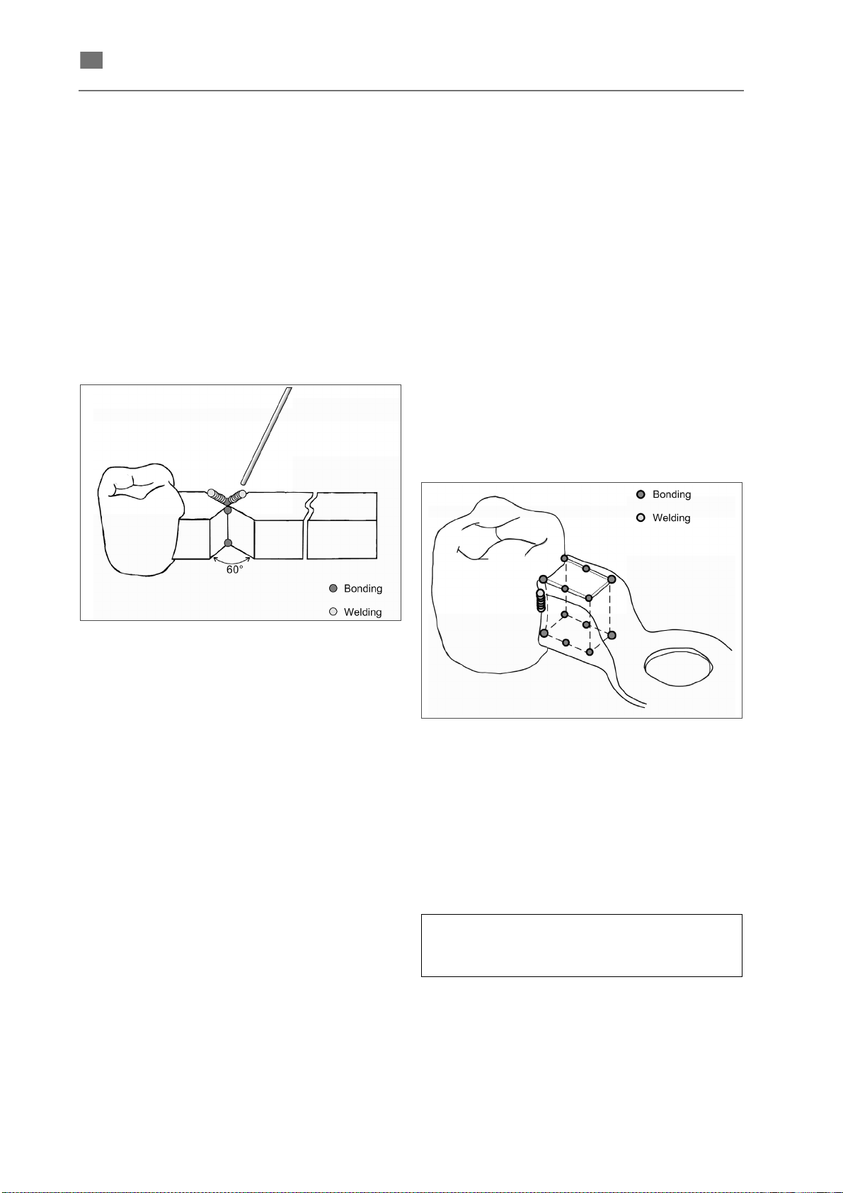
English ⋅ LaserStar T Plus
en
Case examples
The varied options offered by the laser in providing
solutions for dental welding work are described on
the basis of examples below. The methods
proposed can be applied analogously to many other
welding tasks.
Welding secondary crowns to partial dentures
Welding on entire surface with double-V seam joint
In the wax-up give the parts of the joint located
opposite each other a wedge shape so that a
double-V seam joint results when the cast objects
are joined on the model (see Fig. 41).
generate cracks in the non-precious material which
would have to be ground and filled again in any
case.
Box-peg joint
Prepare the wax-up with a peg at the precious-metal
outer crown and with a box on the partial denture
part (Fig. 42). The gap between the workpieces
should be kept as minimal as possible.
Fig. 41 Double-V seam joint
The beam angle should be approx. 60° in solid
places so deep penetration welding can also be
carried out. The two sharp edges should touch each
other.
Fix the parts at at least two points located opposite
each other. After that allow the filler metal to drip
spot by spot and fill the entire double-V seam joint in
this way. Begin at the deepest point of the seam and
apply the spot welds in individual layers alternately
on both sides of the seam.
Attention: If cracks appear next to the wire during
welding of the deepest layers, grind them and weld
them closed at a low energy level layer by layer,
otherwise the homogeneity of the weld is not
guaranteed.
Note: It is advantageous initially to weld on the
precious filler metal on the entire surface on the
non-precious metal side in order to produce a buffer
layer. In this way the gold wire flows better during
further welding and better mixing takes place.
Without this gold buffer layer the laser beam may
Fig. 42 Box-peg joint
Welding on the model begins with tacking while
initially fixing the two parts with opposite spots at the
same time. After that weld the joints together at a
moderate energy level with considerably (approx.
80%) overlapping spots. To avoid stress, always
place only partial seams on each side until the joint
is complete.
Welding parameters (basis for own tests):
- see the separate tables "Setting combinations"
and "Preset parameters".
86076 DB-en/03 355.00032
48
Page 52
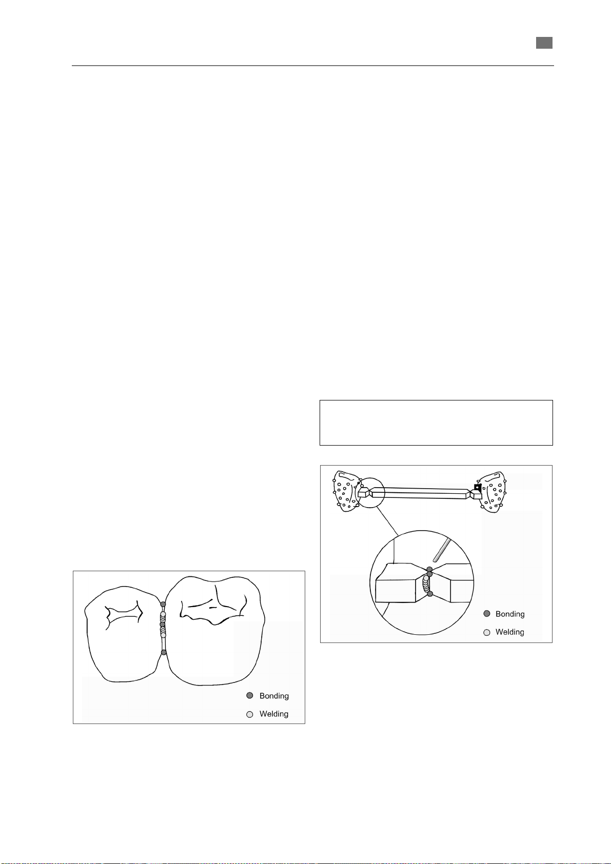
English ⋅ LaserStar T Plus
en
In this welding operation the seam dips along its
entire length in the gap due to the physical
processes during melting and rehardening. The
subsequent smoothing at a low energy level should
not be carried out until the seam appears flawless
without any cracks after a thorough check.
Otherwise it is recommended that it be ground and
welded with filler metal.
Alternative: For example, ready-made connecting
elements. Since their geometry is defined and
always the same, the welding parameters can be
saved and used again once they have been determined.
Butt welding
Completing bridges and connecting crowns
a) Precious metal to precious metal
As described in Welding secondary crowns to partial
dentures prepare the contact point already in the
wax-up phase or by grinding the crowns such that a
circumferential single-V butt joint can result when
the object is put together on the model. The beam
angle should be around 45°. First fix the two crowns
with a few spots crosswise. After that take the
workpiece off the model and build up the welding
wire spot by spot in opposite layers until the entire
seam is filled.
If joining is to be carried out subsequently and
adequate space is not available for a single-V butt
joint, a gap can be filled by inserting a thin plate which is cast or a wire beaten flat can be used - and
welded homogeneously all around with spot welds
that overlap by approx. two thirds in each case (Fig.
43). This method does not result in full-surface
welding, but "circular deep penetration welding".
b) Precious metal to non-precious metal
Prepare the two parts of the joint similar to a), tack
on the model and weld together on the model layer
by layer with intermediate checks after raising. Prior
to tacking the entire welding surface of the nonprecious side can be coated with the specified
welding wire spot by spot with around two thirds
overlapping in thin layers next to each other.
Welding bars to or between crowns
When joining bars, weld the spots to form a doubleV butt joint (Fig. 44). Welding of the various combinations is carried out as described in Case
examples. To fix, place the abutment crowns on the
model and position the bar in contact in the parallelometer using adhesive wax. After that fix the bar
with a few spots opposite each other at the deepest
points of the seam and complete the weld for fitting
accuracy layer by layer with intermediate checks
after raising.
Important: Completely finish one bar-crown joint
after the other.
Welding parameters (basis for own tests):
- see the separate tables "Setting combinations"
and "Preset parameters".
Fig. 44 Connecting bars
Fig. 43 Connecting crowns
86076 DB-en/03 355.00032
49
Page 53
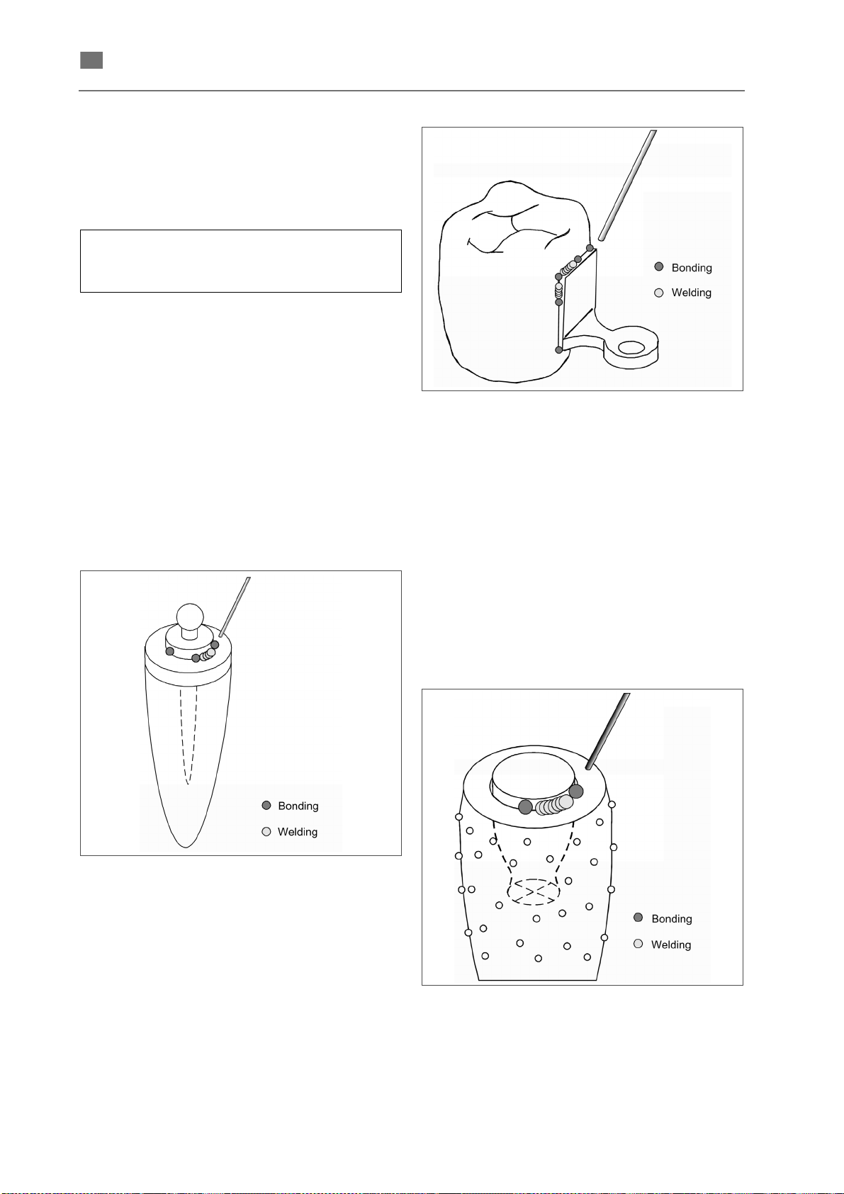
English ⋅ LaserStar T Plus
en
c) Titanium
The parts must be ground appropriately for precise
fitting in order to join titanium. If necessary, make
adapters out of sprues or insert filler metal. Never
anneal or grind the titanium too hot.
Welding parameters (basis for own tests):
- see the separate tables "Setting combinations"
and "Preset parameters".
Use titanium of a graduation as far as possible.
Extracoronal and intracoronal connecting
elements
Roach ball, Bona anchor and button anchor
Always weld attachment parts or anchors with base
or backing plates with thin precious-metal welding
wire, as shown in the following figure for a Roach
ball. Set the welding intensity according to the alloy
for the abutment, precious metal or non-precious
metal, taking into account the notes and instructions
in the previous sections.
Fig. 46 Welding parallel attachment
Welding individual attachments
In the case of RSS attachments, locks, anchor male
parts in the partial denture, etc., weld precision pins
for friction on the model as in the following figure.
Welding precision pins for friction
Expand the drilled hole at the exit point into a
trumpet shape. Cut off and grind down the pin such
that it projects only around 0.5 mm. Fill the circumferential gap with dripping precious-metal welding
wire - also in the case of steel pins. First weld the
opposite partial seams here.
Fig. 45 Welding Bona anchor
Parallel attachment and anchor female parts
Place the female part with its backing plate in
position on the crown in the parallelometer and fix
with wax. Here the attachment parts can first be
fixed at the opposite corners with initial spot welds
without further parallelization. After that complete
the joint on the outer circumference with welding
wire making sure always to weld only short partial
seams on opposite sides (see Fig. 46).
50
Fig. 47 Welding individual attachment
86076 DB-en/03 355.00032
Page 54
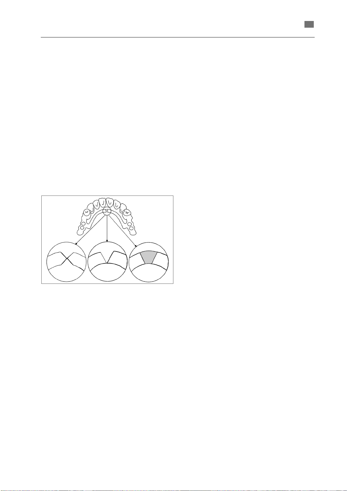
en
Repairs and extensions
English ⋅ LaserStar T Plus
Bar break and clasp break
In the case of non-precious metal and precious
metal, grind the break points of the two parts to be
joined and, prepared in this way with a double-V butt
joint, place on the model (Fig. 48). Then tack the
joint as described in "Completing bridges" and weld
with welding wire. After tacking and welding the
deepest layer on one side, the opposite side should
also be welded with a layer - after grinding if
necessary - in order to counteract stress. Preparation can also be carried out as a single-V butt joint
only with thin parts or it can be dispensed with it
altogether (e.g. clasps).
In the case of larger distances- for example,
sublingual bar break - cut out the break point
spaciously and insert and weld a trapezoidal
adapter.
Building up contact points
(build-up welding)
Material is built up in layers using welding wire of the
same alloy, letting the wire drip from the tip to build
it up spot by spot. Finally the built-up material can be
reworked and smoothed at the same time.
Welding bar sleeve with partial denture
The bar sleeves are frequently so thin that they melt
thoroughly at an excessively high energy level due
to the laser welding pulse and are joined to the bar.
This welding work is carried out more successfully
on the plaster model.
Fill the silicone mould for the duplicate model with
plaster again, position the precious-metal bar
sleeve on it as specified and put on the partial
denture. After the first fixing by means of opposite
spot welds the object can be taken off the model.
The bar sleeve can now be welded at a low energy
level while adding welding wire of the same alloy
without welding the sleeve to the metal bar. Insulate
the bar and rider beforehand with graphite paste or
Vaseline.
Fig. 48 Repairing sublingual bar break
Filling defects, cavities, cracks, etc.
Expand all defects by means of grinding and fill with
welding wire of the appropriate alloy layer by layer
from the deepest point to the surface with a slight
overcontour. After that rework the weld by grinding.
Extending crown border
Tapering edges are all too easily melted away with
the laser beam. Therefore, always allow wire as filler
metal to drip at a low energy level. It is helpful to
grind the edges down to a minimum wall thickness
of approx. 0.5 mm beforehand.
A part that has been shaped appropriately through
grinding, casting or bending is to be bevelled slightly
at the edge to form a single-V butt joint and tack on
the model at a low energy level. After that fill the
seam with welding wire layer by layer at the same
low energy level as described in the previous
sections.
The best method is to weld on a cast adapter.
86076 DB-en/03 355.00032
51
Page 55
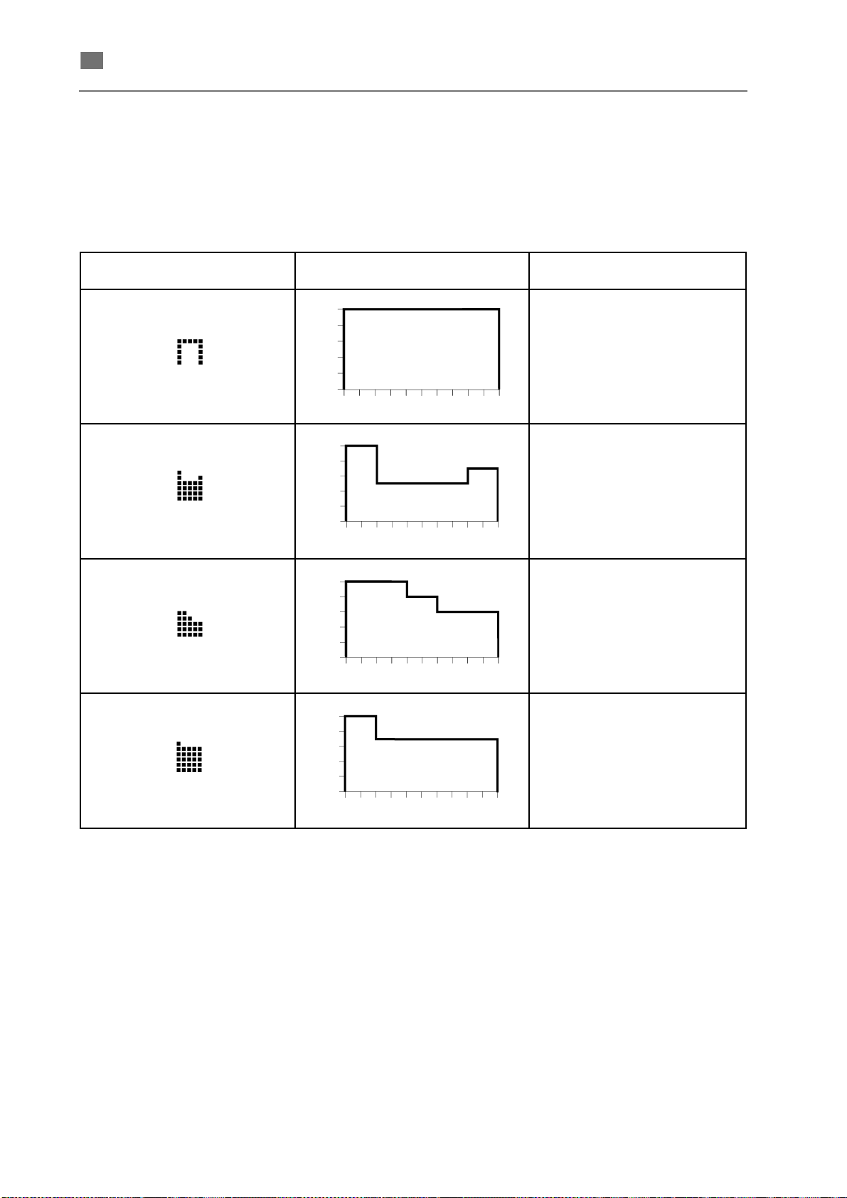
English ⋅ LaserStar T Plus
en
Pulse shapes
The shape of the laser pulse (i.e. the curve of the
intensity of the laser beam over time) has a significant influence on the behaviour of the material and
thus on the welding result.
The LaserStar T plus plus welding laser has four
fixed preset pulse shapes, which can be selected for
processing, like the other parameters, and can be
stored together with the other parameters.
The following pulse shapes are available:
Symbol
Intensity curve
(schematic)
Applications
Standard pulse shape
incl. titanium
Gold-base alloys
(Bio PontoStar XL,
PlatinLloyd)
Non-precious alloys
(Wirobond, Wironit)
52
Palladium-base alloys
> 20% Pd
(BegoPal 300)
86076 DB-en/03 355.00032
Page 56
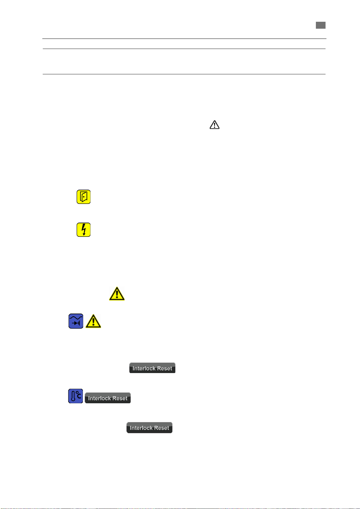
en
Status and error messages/
Fault clearance
General information
English ⋅ LaserStar T Plus
Status and error messages are displayed as
symbols at the top edge of the touchscreen.
The different types of status and error messages are
characterized by the following colors and displays.
Status messages
Messages that display normal operating states are
show as individual symbols without additional information.
Examples: = Safety circuit interrupted (such
as working chamber door not
closed)
lamp not yet ignited.
Error notes
This type of messages indicates states that may
cause subsequent malfunctions. The laser,
however, temporarily remains operable.
In the table in the following section, this error classification is referred to in the column Type by the
symbol or the abbreviation IL.
The arising error measures are saved and can be
viewed in the History window of the --> SERVICE
MENU USER.
In this cases the symbol is displayed in
addition to the specific error symbol.
Example:
Interlock error messages
In the case of malfunctions that cause the device to
turn off for security reasons, the
button is displayed in addition to the specific error
symbol.
Example:
cooling water temperature exceeded.
The device will only work after eliminating the fault
and subsequently pressing the
button.
86076 DB-en/03 355.00032
= water flow too low.
= permissible
53
Page 57
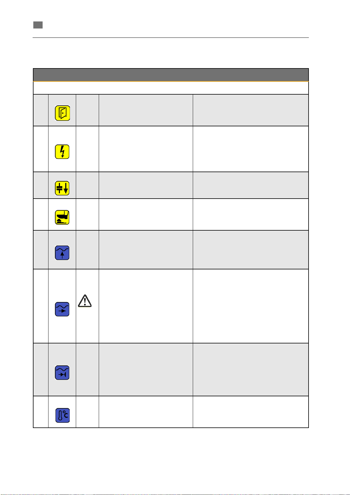
English ⋅ LaserStar T Plus
en
Status / error messages, causes and remedy
No. Symbol Type Meaning/Explanation Measures
Completely close the working chamber
1
2
Working chamber door not or not
completely closed.
The Lamp is not yet ignited.
If the system is switched off and on
again very quickly, the laser's
power supply unit is discharged for
safety reasons. This can take several minutes.
door.
If the symbol keeps on being indicated, please contact the service department.
Wait until the capacitor bank is charged.
3
4
5 IL Water level in the tank too low.
6 The water flow is too low.
7 IL The water flow is insufficient.
The capacitor bank is being
discharged.
If the working chamber door is opened and then closed again while
the pedal switch is depressed, the
shutter closes for safety reasons.
Wait until the voltage of the capacitor bank
reaches the new value.
Take your foot off the pedal switch.
Check water level.
Fill the tank to the maximum mark with DI
water.
If the symbol keeps on being indicated, please contact the service department.
Check if there is a kink in the cooling hose.
Check the circulating pump and permeability of the filter by disconnecting the return
line from the filter and feeding it directly into
the supply tank.
Clean the coolant circuit (e. g. after a very
long period out of use or after a lamp breakage).
If the symbol keeps on being indicated, please contact the service department.
Check if there is a kink in the cooling hose.
Check circulation pump.
Clean the coolant circuit (e. g. after a very
long period out of use or after a lamp breakage).
If the symbol keeps on being indicated, please contact the service department.
8IL
54
Maximum permissible temperature
of the cooling water exceeded.
Check the ventilators.
The ambient temperature is too high.
If the symbol keeps on being indicated, please contact the service department.
86076 DB-en/03 355.00032
Page 58
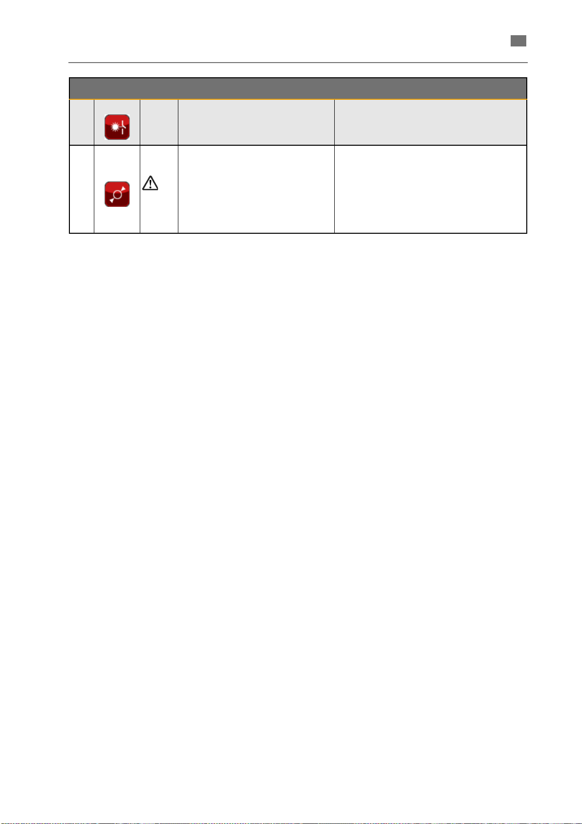
English ⋅ LaserStar T Plus
en
No. Symbol Type Meaning/Explanation Measures
9 IL Shutter fault Please contact the service department.
Switch the device off and on again several
times, and note the time it takes for the
10
Focus fault The entered value for
the focus setting could not be reached.
power supply unit to discharge (see error
message 2).
Check connections.
If the message keeps on being indicated,
please contact the service department.
86076 DB-en/03 355.00032
55
Page 59
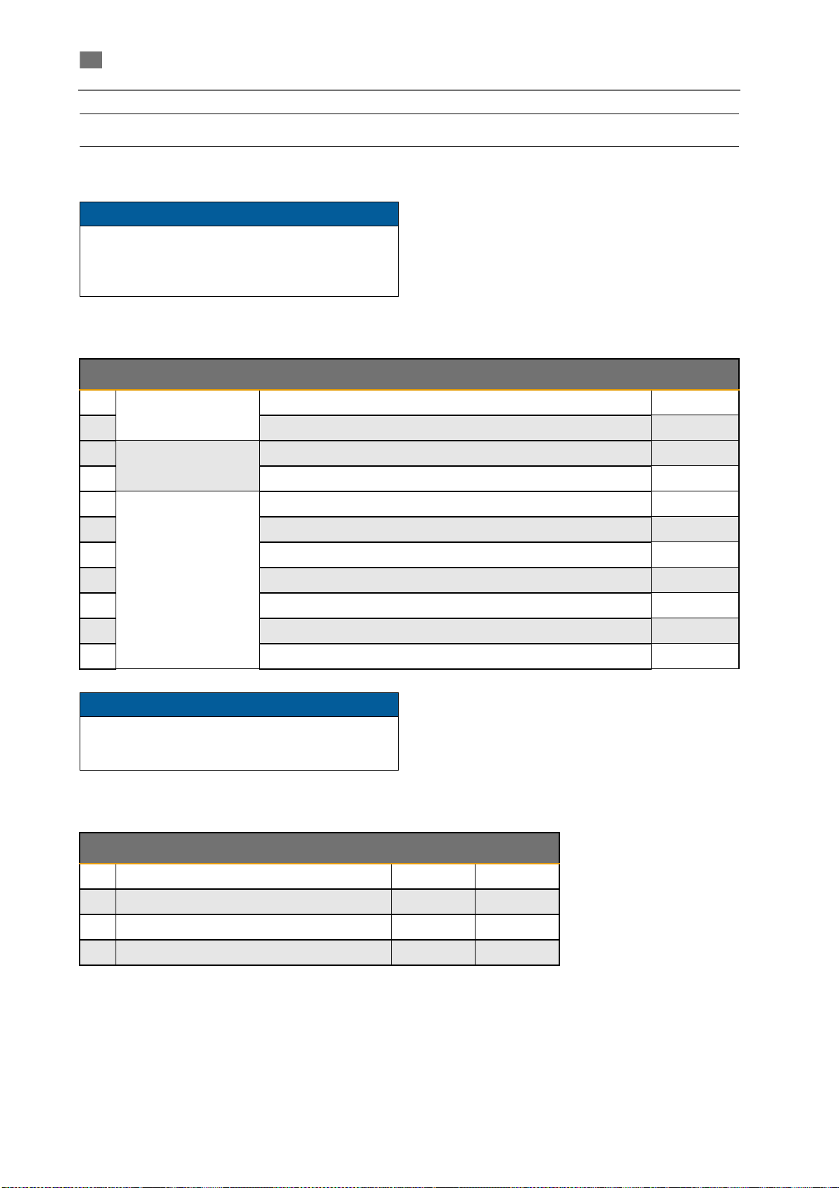
English ⋅ LaserStar T Plus
en
NOTE
NOTE
Service and maintenance
A faultless operation of the device and best
welding results can only be obtained if the
maintenance activities have been executed
correctly and within the prescribed intervals.
Material
No. Material Name REF
1
Expendable items
2 Filter fabric 18588
3
4 Cuff for hand openings (cloth) to be mounted by the customer 18589
5
6 Lens protective glass Ø 38 mm 15990
7 Lens 120 mm 15988
8 Splash protection window 100x50x2mm
9 Protective glass for the ring light 18590
10 Pedal switch(electric) complete 18591
11 Fuse 16 A 18592
The following wear parts will not be replaced
free of charge within the guarantee or the BEGO
warranty.
Wear parts
Spare parts
DI water filter 18587
Laser lamp (standard) 15683
Flow plate (glass between laser lamp and laser rod) 16075
3
15686
Optional equipment
No. Name Quantity REF
1 Filter system Ventus 1 26205
2 Pressure regulator for Argon inert gas 1 13380
3 Lifting table, adjustable in height 1 15649
4 Hand rests, adjustable in height 2 15650
56
86076 DB-en/03 355.00032
Page 60
en
Maintenance (care)
NOTE
DANGER
DANGER
The maintenance of the device reduces to the
cleaning of the surfaces with a damp cloth with light
alkaline solution.
By no means use strong cleaning agents (e.g.
cleaning powder) or solvents!
Maintenance
All maintenance work not explicitly
described in this manual may only be
carried out by specially trained and
authorized service engineers - even
when the laser is switched off.
Maintenance intervals
Daily maintenance
or after strongly splashing welding
• Check the protective glass in front of the lens
at least once a day and, if necessary, clean it
with lens-cleaning paper (e. g. KODAK lens
cleaning paper or Kleenex) soaked in a solvent (propyl alcohol).
• If major metal splashes stay adherent, the protective glass has to be replaced by a new one.
If you don't do this, there is a risk of the glass
being overheated at those points and possibly
cracking, thus causing injury or destroying the
lens (
→ section REPLACING THE LENS
PROTECTIVE GLASS).
Weekly maintenance
• The splash protection window should be checked at least once a week for scratches,
cracks or holes. If the view of the working
chamber is impaired, the splash protection
window should be replaced or cleaned (
tion REPLACING THE SPLASH PROTECTION WINDOW).
→ sec-
English ⋅ LaserStar T Plus
Uncontrolled escape of laser
radiation!
If there are holes in the leather cuffs or
the leather cuffs do not fit tight on the
arms they must be replaced.
Monthly maintenance
or if welding results are unsatisfactory or after each
lamp replacement.
Test the laser energy with trial shots. If the results
are unsatisfactory:
• Check the laser setting including the pulse shape option.
• Check and clean the lens protective glass (
section REPLACING THE LENS PROTECTIVE GLASS).
• If the shot image is round, increase the kW setting. If the output must be increased by more
than 20 %, change the lamp (
REPLACING THE LASER FLASH LAMP).
When satisfactory results cannot be obtained by the
above measures, contact the service department.
Half-yearly maintenance
• Check the water level in the tank (
CHECKING/REFILLING THE COOLANT).
• Clean the heat exchanger blades (
CLEANING THE HEAT EXCHANGER
BLADES).
Maintenance after 2000 operating hours or at least
every year
• Replace the DI water filter (
CING THE WATER FILTER AND THE DI
WATER) and change the deionised water.
• Check safety equipment (see homonymous
section).
→ section
→ section
→ section
→ section REPLA-
→
• Check the leather cuffs and the leather cloths
86076 DB-en/03 355.00032
in the hand openings for signs of wear.
57
Page 61
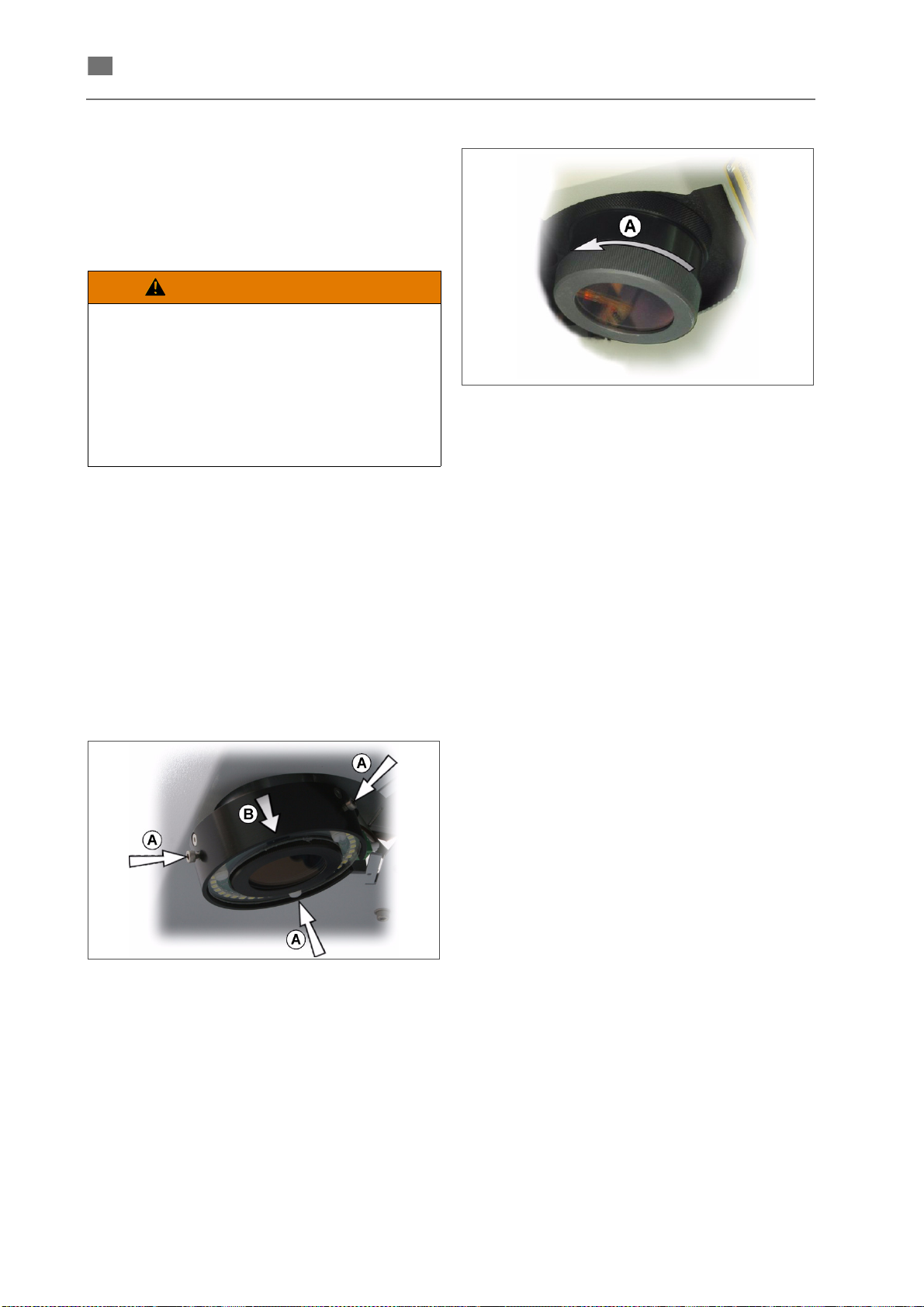
English ⋅ LaserStar T Plus
en
WARNING
Replacing the lens protective glass
The protective glass prevents the lens from being
damaged by mechanical influences as metal
splashes or dust. In order to reduce power losses by
absorption the protective glass is antireflection
coated on both sides.
The lens protective glass should also
be replaced when it is slightly dirty (as
a result of metal splashes, for
example).
If it is not replaced, the laser beam may
heat it so excessively at those points
that it can crack and cause injury and
further damage.
If the glass is dirtied by welding smoke, it is
generally enough to clean it with alcohol/spirit. If
particles are burned in, however, it has to be
replaced.
Fig. 50 Removing protective glass
5. Replace the old glass by a new one.
6. Screw the knurled ring together with the new
class at the underside of the lens by turning it
clockwise.
7. Refit the ring light (if applicable).
Procedure
1. Switch off the laser: Turn the Laser key switch
to "0" position and the main switch "0" position.
2. Open the working chamber door.
If the device is equipped with the ring light option:
Fig. 49 Removing ring light
3. Loosen the three Allen screws (see arrows (A)
in Fig. 50 - the third screw is not visible), and
pull the ring light downward (arrow B)).
4. Unscrew the knurled ring (A) at the underside
of the lens counterclockwise, remove it and,
holding it as horizontal as possible, take it out
of the working chamber.
86076 DB-en/03 355.00032
58
Page 62
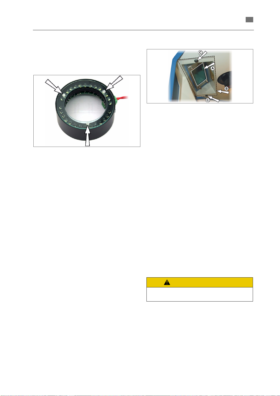
English ⋅ LaserStar T Plus
en
CAUTION
Replacing the ring light protective glass
If the device is equipped with the optional ring light,
the protective glass on the ring light only needs to be
replaced if it is defective or so dirty that the lighting
provided is no longer adequate.
Fig. 51 Replacing the ring light protective glass
Procedure
1. Switch off the laser: Turn the Laser key switch
to "0" position and the main switch "0" position.
2. Open the working chamber door.
3. Remove the ring light as described in the previous section (
TECTIVE GLASS).
4. Remove the three plastic screws, and replace
the glass.
5. Screw the plastic screws in again carefully, but
not too tightly.
6. Refit the ring light.
→ REPLACING THE LENS PRO-
Replacing the splash protection window
Fig. 52 Replacing the splash protection window
The observation window consists of two glasses:
• The laser protective window (yellowish green
window on the outside - position (A) in the
figure below) prevents the emission of laser
radiation and ultra-violet light.
• The splash protection window ((B) on the inside
of the working chamber) protects the laser protective window from soiling and damaging.
If the view of the working chamber is impaired, the
splash protection window should be replaced or
cleaned.
Procedure
1. Switch off the laser: Turn the Laser key switch
to "0" position and the main switch "0" position.
2. Open the working chamber door.
3. Remove the two Allen screws ((position (C) in
Fig. 52) from inside the welding chamber, and
then remove the splash-protection window (B).
4. Clean the splash-protection window with alcohol or a commercially available window-cleaning agent, or replace it - if necessary - with a
new one.
Do not scratch the splash-protection
window!
5. Secure the splash-protection window in the
device using the two Allen screws (positions
(C)).
86076 DB-en/03 355.00032
59
Page 63
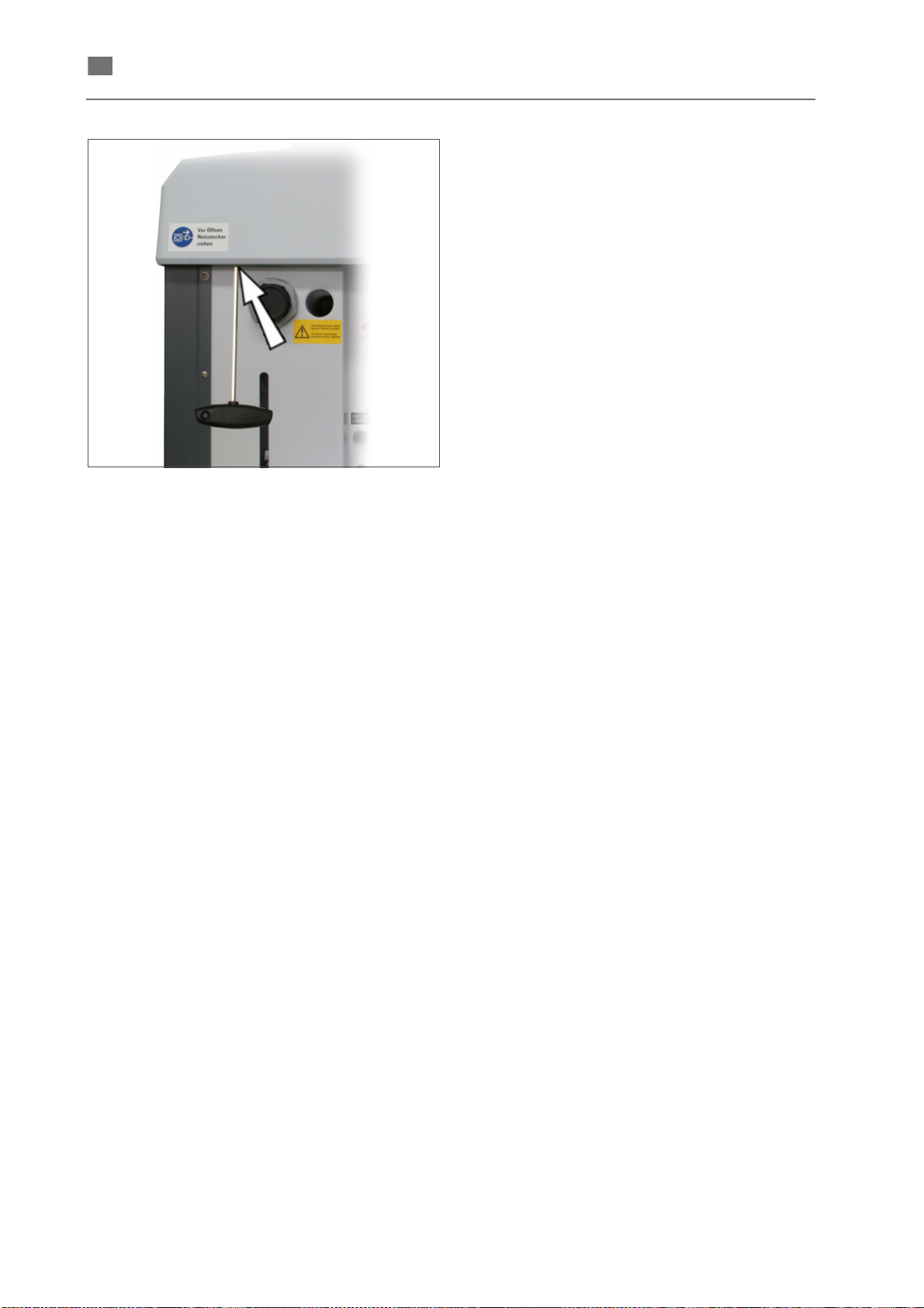
English ⋅ LaserStar T Plus
en
Fig. 53 Allen screws/Rearside of the device
6. Remove the 2 Allen screws at the rear of the
device. The arrow in Fig. 53 shows the position
of the screw on the left side (seen from
behind).
7. Lift up the cover and put it upside down onto
the prepared space left of the device.
Refitting
1. Place the cover on top of the device and tighten it with the four Allen screws.
2. Remount the microscope (
→ MOUNTING THE
STEREO MICROSCOPE).
3. Adjust the microscope (
→ ADJUSTING THE
STEREO MICROSCOPE).
86076 DB-en/03 355.00032
60
Page 64
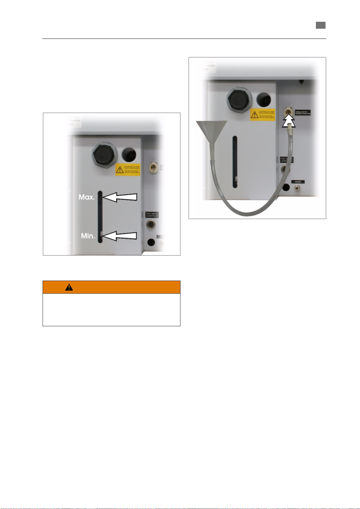
en
Checking/refilling the coolant
WARNING
In the cover on the rear of the device is a recess in
which you can see the coolant level of the supply
tank, and markings for the minimum and maximum
permissible coolant level (see arrows in Fig. 54).
When the water level sinks to the min. level, refill the
tank with deionised water.
English ⋅ LaserStar T Plus
Fig. 54 Coolant level indicator
Avoid any skin or mucous membrane
(nose, eyes, mouth) contact with the
cooling water (
DEIONISED WATER).
Procedure
1. Switch off the laser: Turn the Laser key switch
to "0" position and the main switch "0" position.
→ HANDLING
Fig. 55 Plug in of funnel tube
Refilling deionised water
2. Plug in the quick release coupling of the funnel
tube into the corresponding socket (see arrow
(A) in Fig. 56).
3. Fill in deionized water up to the max. level (see
arrow in Fig. 55).
4. If the device is filled up for the first time switch
on the main switch so that the pump starts up
and the air is removed from the coolant circuit.
(The water level in the supply tank sinks considerably.) Then fill up again with DI water up to
the maximum level.
5. Press down the lock (see arrow (B) in the
figure above) and pull out the funnel tube.
86076 DB-en/03 355.00032
61
Page 65
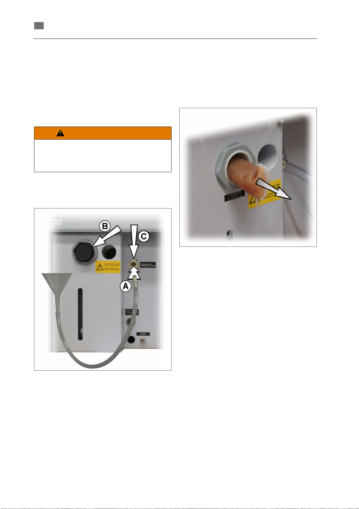
English ⋅ LaserStar T Plus
en
WARNING
Replacing the water filter
Procedure
1. Switch off the laser: Turn the Laser key switch
to "0" position and the main switch "0" position.
2. Unplug the power cord!
3. Prepare a suitable container to collect the used
deionized water (capacity min. 10 liters).
Avoid any skin or mucous membrane
(nose, eyes, mouth) contact with the
cooling water (
DEIONISED WATER).
4. Plug in the quick release coupling of the funnel
tube into the corresponding socket (see arrow
(A) in Fig. 56).
→ HANDLING
6. Open and remove the closing cap of the water
filter insert (see arrow (B) in Fig. 56).
7. Pull out the filter cushion (see Fig. 57).
Fig. 56 Replacing the water filter
5. Drain the water tank completely.
In case the water does not flow out by itself fill
the hose with water prior to connecting it.
Fig. 57 Pulling out the filter cushion
8. Push in the new filter cushion into the opening
to the block and close it again with the closing
cap.
9. Fill the tank to the maximum mark with DI
water (see Fig. 54).
10. To remove the filling hose press down the lock
(see arrow (C) in Fig. 57).
11. Plug in the power supply plug.
12. Switch the main switch so that the pump starts
up and the air is removed from the coolant circuit. (The water level in the supply tank sinks
considerably.)
13. Fill up with DI-water until the maximum water
level mark is reached (see Fig. 54).
86076 DB-en/03 355.00032
62
Page 66
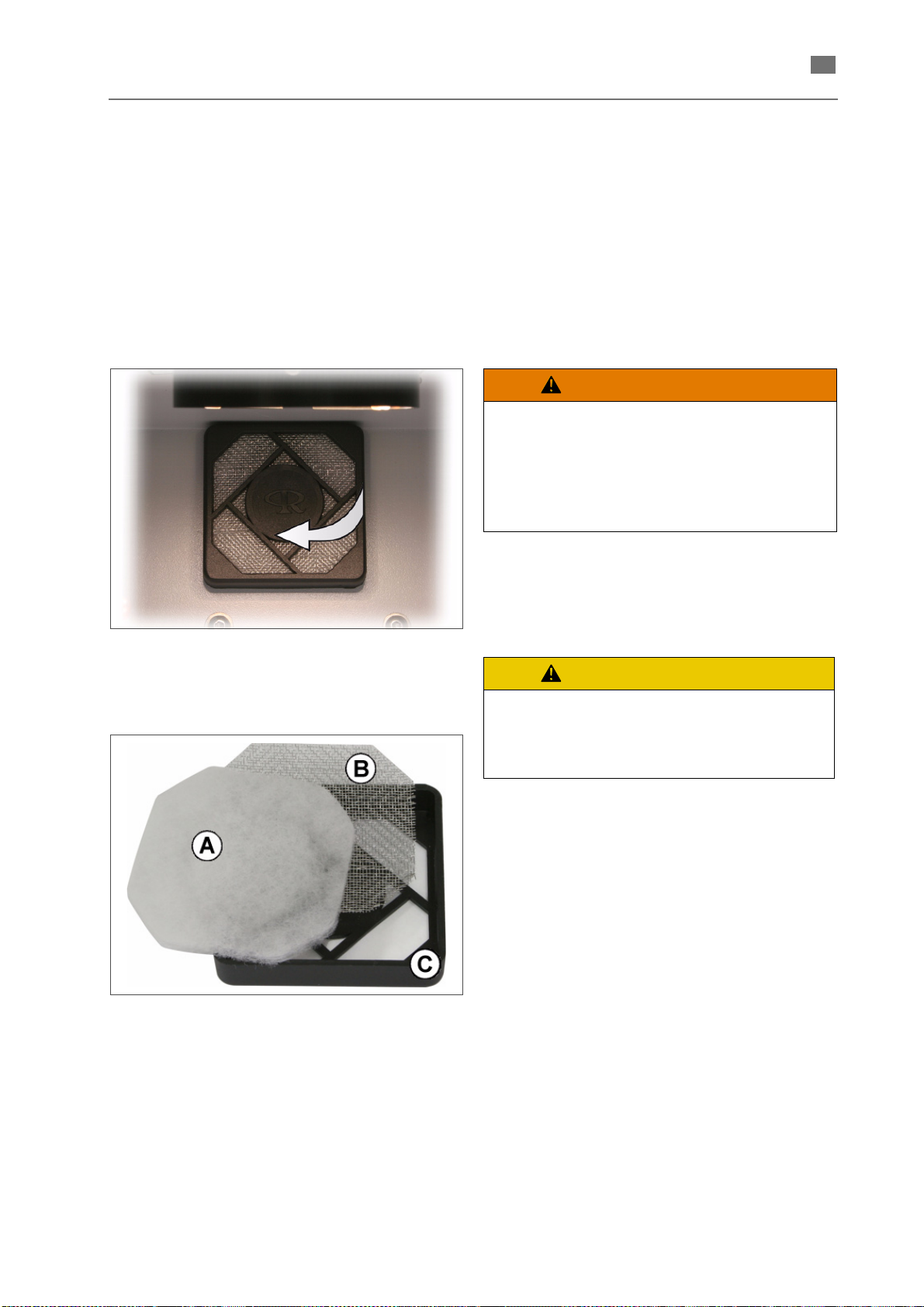
en
Replaicing the air filter
WARNING
CAUTION
The device is equipped only with a simple air filter
consisting of a filter fabric and a spark protection
mat (see Fig. 58 and Fig. 59).
Procedure
1. Open the working chamber door.
2. Draw off the filter frame (see arrow in Fig. 58).
Just pull the frame at a side in order to loosen
the snap-on fixture.
English ⋅ LaserStar T Plus
Do not clean the filter!
Beating or blowing out with
compressed air will destroy the filter
medium.
The pollutants attached to the filter will
get into the air of the working area.
Fig. 58 Drawing off the filter frame
3. Remove the filter fabric (see (A) in Fig. 59) and
dispose of it properly.
Fig. 59 Removing the filter fabric
4. Clean the spark protection mat (see (B) in Fig.
59) using a damp cloth and a mild soap solution when deposits are visible on it.
Pay attention to the correct order when
reassembling the filter components.
Otherwise there is a risk that welding
sparks scorch or torch the filter fabric.
5. Refit the filter unit at the rear of the working
chamber.
(A) Filter fabric
(B) Spark protection mat
(C) Filter frame
86076 DB-en/03 355.00032
63
Page 67

English ⋅ LaserStar T Plus
en
Setting combinations
Situation
1 Clasp break partial denture (Co-Cr) 270 4,0 0,6
2 Break in sublingual bar (PD) 280 4,0 0,4
3 Cavity in partial denture frame 280 4,0 0,7
4 Retentions (bent) to partial denture 270 6,0 0,7
5 Upper-jaw base extension 270 4,0 0,6
6 Precious-metal secondary crown to partial denture 290 9,0 0,6
7 Precious metal bar sleeve to partial denture 290 8,0 1,0
8 Anchor / attachment male parts to partial denture 300 8,0 1,2
9 Build up crown border (Precious metal) 270 3,0 1,0
10 Defects in precious-metal crowns 280 4,0 1,2
11 Weld precious-metal bridge 290 10,0 0,4
12 Align precious-metal bridge 290 6,0 1,0 no
13 Build up contact points (precious metal) 290 4,0 1,2 yes
Precision pins for friction to telescopic crowns (pre-
14
cious metal)
Increase friction of secondary crowns (precious
15
metal)
16 Dolder bar to crown (precious metal) 270 2,5 1,0 yes
17 Build up crown border (non-precious) 240 5,0 0,4
18 Fill cavities in non-precious crowns 270 5,0 0,5
19 Weld non-precious bridges 280 5,0 0,4
VoltageVTime
ms
280 4,0 1,2 no
260 2,5 1,0 no
Focal
point
Filler metal of
the same type
Ø
necessary?*
yes
yes
yes
Partial denture
Precious metal
20 Align non-precious bridges 300 5,0 0,8 no
21 Weld palladium-base crowns together 290 7,5 0,6
22 Partial denture to palladium-base crowns 280 6,5 0,6
23 Clasp break partial denture (titanium) 270 2,5 1,0 no
24 Break lingual bar (titanium) 260 3,0 0,8 yes
25 Weld titanium bridge 300 3,5 1,0 no
26 Titanium: bar to implant 280 2,5 1,2 no
27 Titanium to precious metal 290 3,0 1,2 yes
28 Weld orthodontic wires 240 3,0 1,2 yes
* If different alloys are welded together, always use the higher-quality filler metal.
• All values indicated are only reference values and a basis for your own tests!
• Feed argon correctly to the welding point!
Service Tel.: +49 421 2028-282 / -379
yes
Non-precious
Pd
Titanium
KFO
86076 DB-en/03 355.00032
64
Page 68
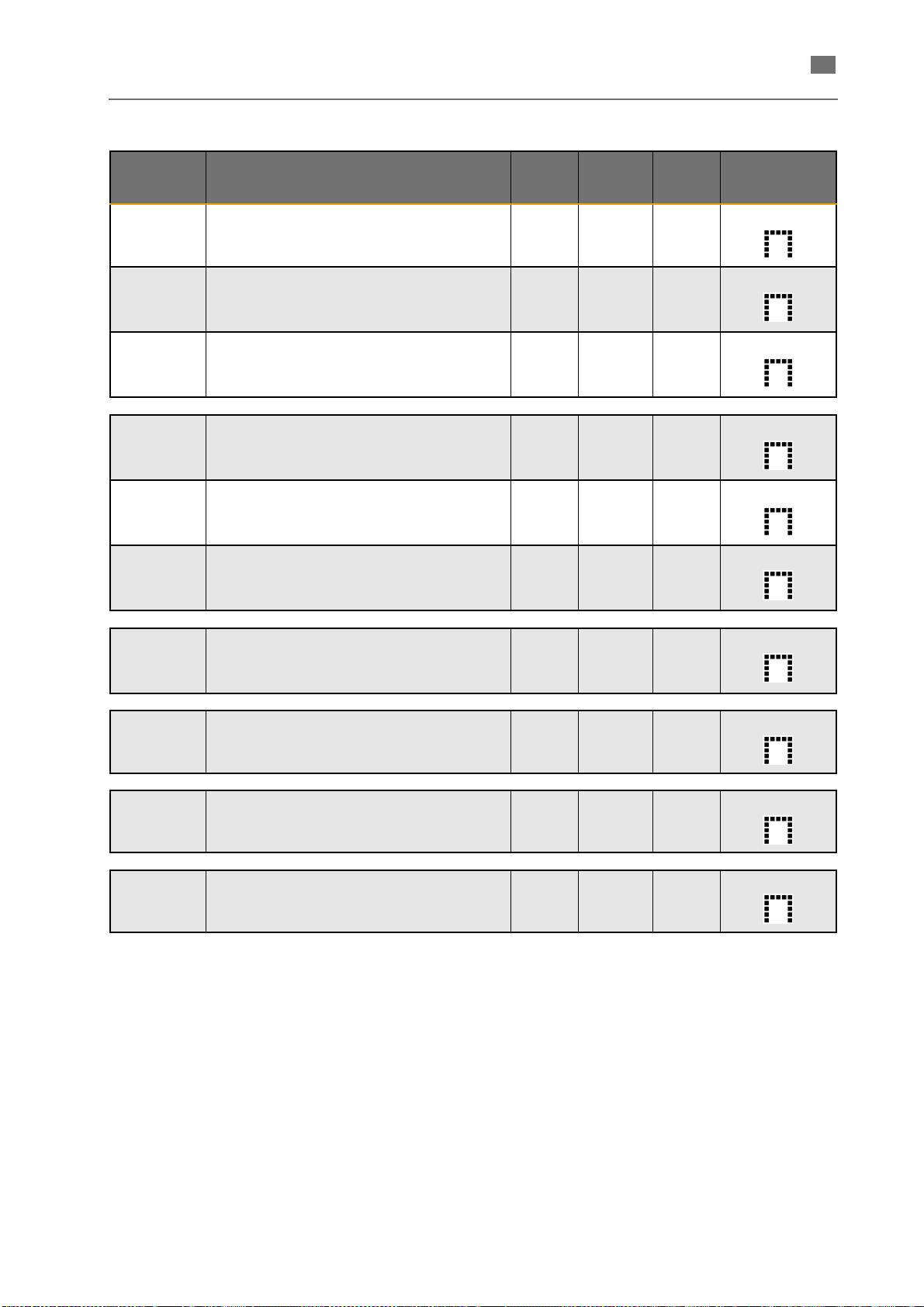
en
Preassigned parameter values
English ⋅ LaserStar T Plus
Memory
location
1
2
3
4
5
6
Display
Application
Clasp break PD
Clasp break in partial denture
Retentions to PD
Partial denture retentions to
partial denture
PA to PD
Precious-metal secondary
crown to partial denture
Weld PA bridge
Weld together
precious-metal bridge
cont. Point PA
Build up contact points
(precious metal)
Frict.sec.crown
Increase friction of secondary
crowns (precious metal)
Voltag eVDurationmsFocus
Ø
270 4,0 0,6
270 6,0 0,7
290 9,0 0,6
290 10,0 0,4
290 4,0 1,2
260 2,5 1,0
Pulse
shape*
Weld NP bridges
7
8
9
10
* The preset pulse shape is the standard pulse shape with the maximum possible energy. If a different
pulse shape is selected, the other parameters have to be adapted accordingly.
• All values indicated are only reference values and a basis for your own tests!
Weld together
non-precious bridges
Pd↔Pd base alloy
Between palladium base alloys
Weld bridge Ti
Weld titanium bridge
Weld Ni wire
Weld orthodontic wires
280 4,0 0,4
290 7,5 0,6
260 2,5 0,8
240 3,0 1,2
86076 DB-en/03 355.00032
65
Page 69
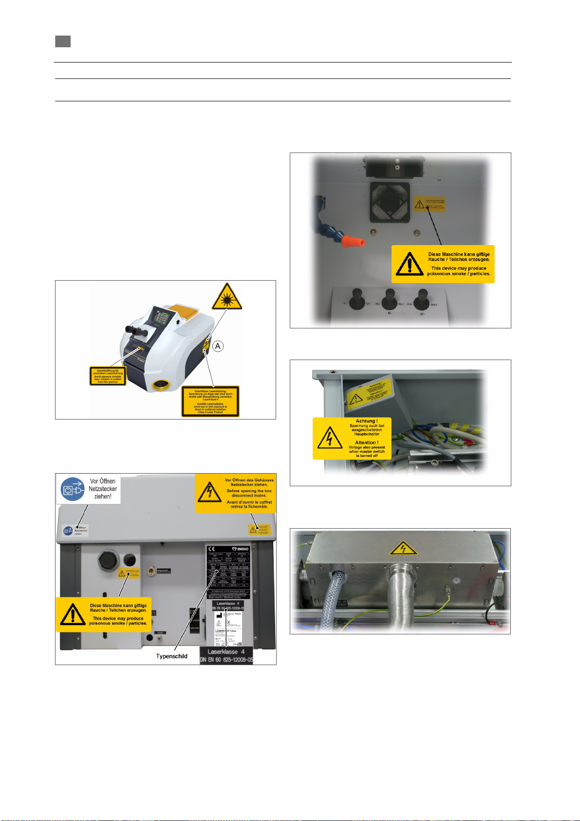
English ⋅ LaserStar T Plus
en
Marking
Warning signs and information signs
All points where any danger might arise under
certain circumstances (e.g. when safety covers are
opened) are marked with the stipulated warning and
explanatory signs. The location of the signs is
shown in the following figures.
These signs may not be removed. If one of these
signs has been removed for any reason, or if it is
missing, it must be reapplied in the same position
before the device is switched on.
Fig. 60 Warning signs
(A) = on both sides of the device
Fig. 62 Warning sign in the working chamber
Fig. 63 Warning sign at power input filter
Fig. 64 Warning sign at EMV cover
Fig. 61 Warning and information signs at the back of
the device
86076 DB-en/03 355.00032
66
Page 70
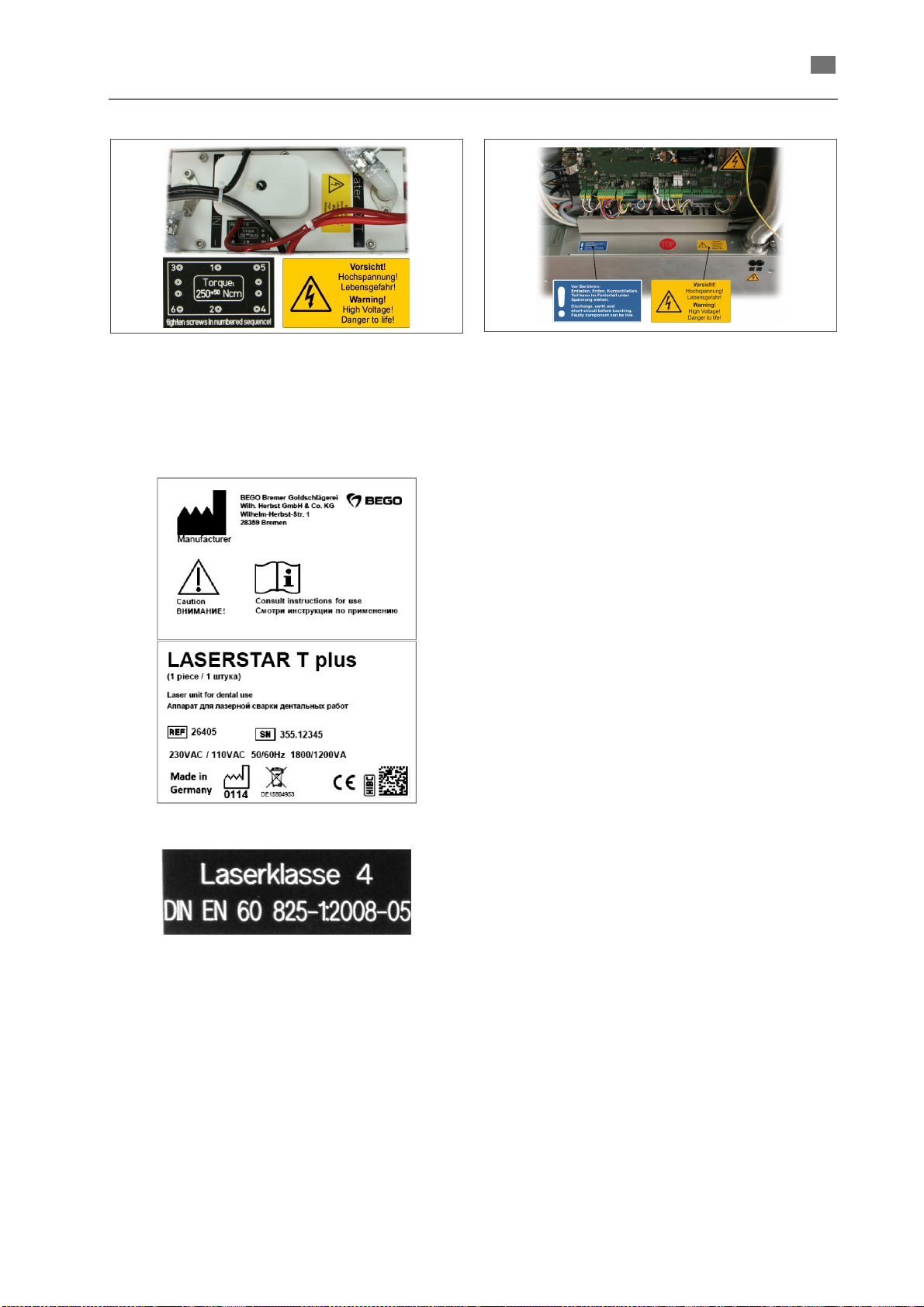
English ⋅ LaserStar T Plus
en
Fig. 65 Warning and information signs on top of the
excitation unit
Device designation
Fig. 66 Warning signs at power supply of lamp and
SCU
Fig. 67 Type plates
86076 DB-en/03 355.00032
67
Page 71

English ⋅ LaserStar T Plus
en
Disposal
Properly handle and dispose of used substances
and materials (such as filters and solvents for
cleaning).
After taking the machine out of service, properly
dispose of the following components according to
local regulations.
• Metals
• Plastics
•Cables
• Packaging
• Packaging materials
• Textiles
• Batteries
• Electrical devices
• Electronicscomponents
• Means of transportation (pallets, etc.)
Instructions for disposing of the device
(Applicable only within the European Union.)
The adjacent symbol on the ID plate of the BEGO device indicates that the device,
in accordance with the European directive on waste electrical and electronic
equipment, may not be disposed of as normal domestic waste.
As a customer, you contribute to the protection of the environment when you dispose
of the device correctly.
Disposal in Germany
BEGO offers you a disposal solution for all BEGO devices sold and put into operation
in Germany subsequent to August 13, 2005. Please contact us when it is time to
dispose of the device.
Disposal in other countries of the European Union
Please contact the company from which you purchased the BEGO device when it is
time to dispose of it. They will provide you with information concerning correct
disposal in your region.
86076 DB-en/03 355.00032
68
Page 72

en
Index
English ⋅ LaserStar T Plus
A
Adjusting the crosshair and focal plane 29
Adjusting the stereo microscope
Alphanumeric input window
Ambient conditions
Ascertaining the real maximum power
Avoiding stress
24
47
29
18
30
B
Basic Equipment 25
Basic instructions
BEGO filler metals for laser welding
Blinding hazard
Butt welding
42
44
8
49
C
Centering the crosshair/welding point 29
Change engineer password
Check safety equipment
Checking/refilling the coolant
Connecting load
Contact information
Conventions
Coolant level indicator
24
3
4
22
32
61
61
D
Danger from the laser beam 8
Descriptions of the menus
Device designation
Diagnosis
Disassembling (preparation for transport)
Display and operating elements
23
66
15
13
E
ECO-Modus settings 38
Edit pulse shape
Electrical data
Elektromagnetic compatibility (EMC)
EMERGENCY STOP button
EMERGENCY STOP devices
Extracoronal and intracoronal connecting elements
50
36
12
12
13
7
F
Faulty operations 41
Filling up and connecting
Fire hazard
First putting into operation
Fix ("bond") on the model
Footswitch
Function test of the EMERGENCY STOP button
Function test of the safety switch of the working
chamber door
86076 DB-en/03 355.00032
8
14
32
28
29
47
30
G
General Functions 18
General information
General instructions
General instructions concerning the service menus
18
53
31
H
Handling deionised water (cooling water) 9
Harmful gases and vapors
Hazard during normal operation
Hazardous areas
How to operate
7
17
9
8
I
Importance of the operating instructions 3
Improper use
Installation
Installation site
Interlock circuit
6
25
24
15
J
Jobs that may only be done by authorized service
personnel
10
K
Key switch 13
L
Lamp pulse counter 21
Lamp settings
Lamp warn level
Laser data
Loading laser parameters (memory manager)
Log book
21
21
12
41
M
Main menu 15
Main switch
Maintenance (care)
Maintenance intervals
Material
Mounting the stereo microscope
13
57
57
56
26
N
Noises 9
Normal welding mode
9
O
Obilgations of personnel 8
Obilgations of the employer
Operating elements in the working chamber
33
Optional equipment
Organizational and personnel measures
Overall view
11
56
7
35
14
7
69
Page 73

English ⋅ LaserStar T Plus
en
P
Pay attention to alloy composition 46
Personal protective equipment
Personnel qualification
Planning the joint
Preassigned parameter values
Preparing surfaces
Product safety
Proper use
Protective coverings
PSU test
6
6
22
8
42
46
7
7
65
R
Repairs and extensions 51
Replacing the lens protective glass
Replacing the ring light protective glass
Replacing the splash protection window
Replacing the water filter
Replaicing the air filter
Requirements
Retrieving and editing pulse shapes (pulse shape
36
editor)
24
62
63
58
59
59
S
Safety and monitoring devices 7
Safety information
Safety switch
Save pulse shape
Saving laser parameters (memory manager)
Select pulse shape
Selecting welding parameters correctly
Service menu ENGINEER
Service menu USER
Service menus
Serving and maintenance
Setting / managing laser parameters
Setting Combinations
Setting workpiece illumination
Shutter status display
Specific safety information
Status / error messages, causes and remedy
Structural modifications to the laser device
Switching inert gas on/off
32
7
37
34
36
46
20
19
18
9
33
64
39
17
9
54
7
39
W
Warning signs and information signs 66
Warranty and liability
Welding individual attachments
What to do if you receive a bum
Workplace
31
5
50
9
T
Tasks that can be performed by the operator 9
Technical Data
Touch screen
Turning off the system
Turning on the unit
12
14
40
31
U
Unpacking 25
Using inert gas
Using welding wire
46
43
V
Visual inspection of the laser protective window 32
70
86076 DB-en/03 355.00032
Page 74
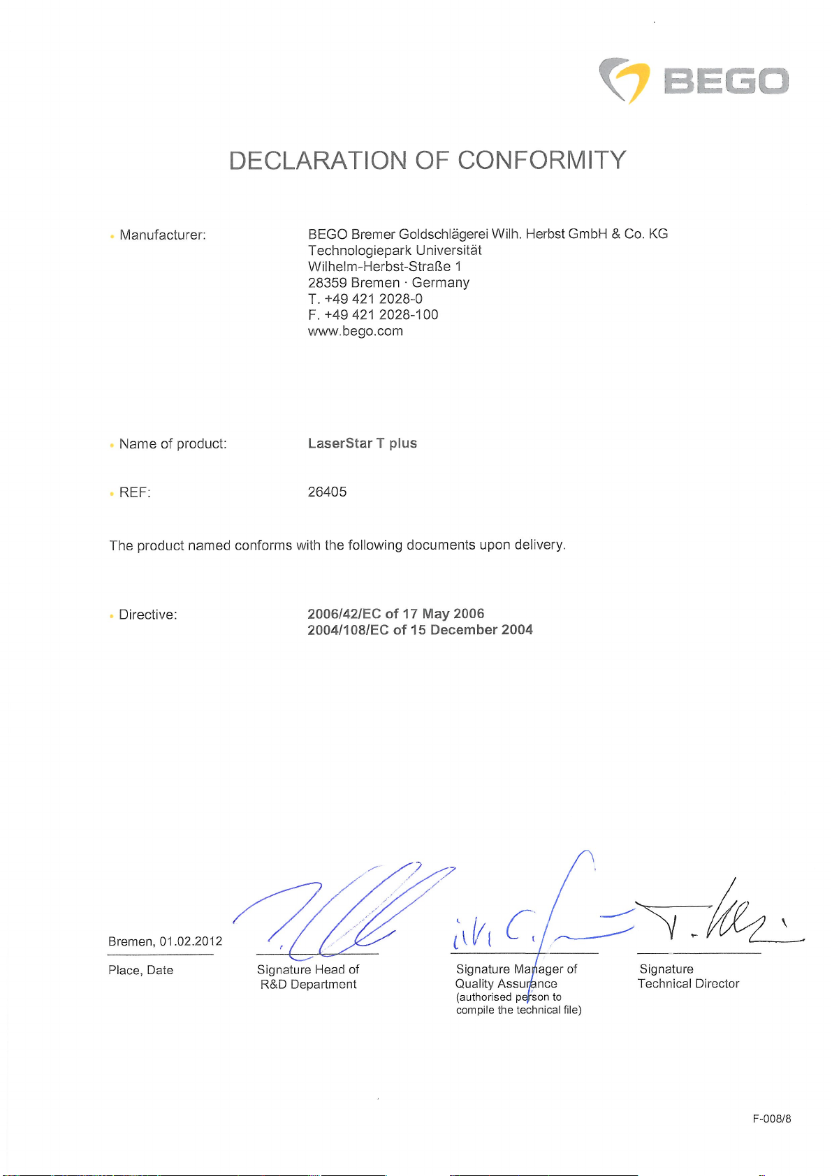
Page 75

Page 76

www.bego.com
BEGO Bremer Goldschlägerei Wilh. Herbst GmbH & Co. KG
Technologiepark Universität · Wilhelm-Herbst-Straße 1 · 28359 Bremen
Telefon +49 421 2028-0 · Telefax +49 421 2028-100 · E-Mail: info@ bego.com
 Loading...