

Page 1
TM
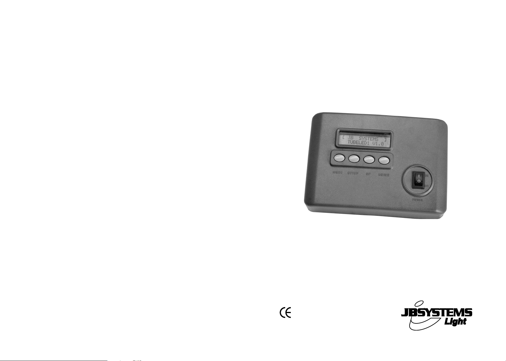
TUBELED
CONTROLLER
FOR INDOOR AND OUTDOOR TUBELEDS
WWW.BEGLEC.COM
Copyright © 2005-2007 by BEGLEC cva.
Reproduction or publication of the content in any manner, without express permission of the publisher, is prohibited.
Version: 1.2
Operation Manual
Mode d'emploi
Gebruiksaanwijzing
Bedienungsanleitung
Manual de instrucciones
Manual do utilizador
EN
FR
NL
DU
ES
PT
Page 2
EN - DISPOSAL OF THE DEVICE
Dispose of the unit and used batteries in an environment friendly manner
according to your country regulations.
FR - DÉCLASSER L’APPAREIL
Débarrassez-vous de l’appareil et des piles usagées de manière écologique
Conformément aux dispositions légales de votre pays.
NL - VERWIJDEREN VAN HET APPARAAT
Verwijder het toestel en de gebruikte batterijen op een milieuvriendelijke
manier conform de in uw land geldende voorschriften.
DU - ENTSORGUNG DES GERÄTS
Entsorgen Sie das Gerät und die Batterien auf umweltfreundliche Art und
Weise gemäß den Vorschriften Ihres Landes.
ES - DESHACERSE DEL APARATO
Reciclar el aparato y pilas usadas de forma ecologica conforme a las
disposiciones legales de su pais.
PT - COMO DESFAZER-SE DA UNIDADE
Tente reciclar a unidade e as pilhas usadas respeitando o ambiente e em
conformidade com as normas vigentes no seu país.
Page 3
ENGLISH OPERATION MANUAL
ENGLISH OPERATION MANUAL
OPERATION MANUAL
Thank you for buying this JB Systems®product. To take full advantage of all possibilities, please read
these operating instructions very carefully.
TheJBSystemsTUBELED™ system contains the followingcomponents:
The 1mlong TUBELED™ tubes: to be connected to the controller.
The TUBELED™ controller:controls the connectedled tubes.
Signal extension cables: 5m or 10m.
Powerextension cables:5m, 10m or 20m.
This manual only explains the functions of the controller.
FEATURES
Dedicatedcontrollerused to control the TUBELED™ led tubes (notincluded)
Controlsup to 4000 tubes, no extrapower boosters needed.
38 preprogrammedpatterns
Automode scans all patterns automatically
Patternselectionby DMX512:
o Channel1:choosepatterns
o Channel2: speed control
o Channel3: intervaltime
o Channel4: strobe/flash rate
RGB color mixing, controlledby DMX512(makeyour own colors):
o Channel1: not used(set to zero)
o Channel2:dimming red color
o Channel3:dimming green color
o Channel4:dimming blue color
Adjustablestrobefunction
Adjustable speed and interval time for most patterns
Nice plasticenclosure can be fixed on the wall
Autosave function: saves the last working mode for all patterns individually.
Perfect for use in: retail stores, commercial displays, architectural lighting, indoor and outdoor
decoration, clubs,pubs, mobile DJs, trussing,…
BEFORE USE
Check the contents:
Checkif the carton contains the following items:
TUBELED™ controller
Mains DC Adapter12V 500mA
Operating instructions
SAFETY INSTRUCTIONS:
CAUT ION
The lightning flash with arrowhead symbol within the equilateral triangle is intended to alert the
use or the presence of un-insulated “dangerous voltage” within the product’s enclosure that
maybe of sufficient magnitude to constitute a risk of electricshock.
The exclamation point within the equilateraltriangle is intended to alert the user tothe presence
of important operation and maintenance (servicing) instructions in the literature accompanying
this appliance.
This symbol means:indoor use only.
This symbolmeans:Readinstructions.
To prevent fire orshock hazard, do notexposethis appliance to rain or moisture.
To avoid condensation to be formed inside, allow the unit to adapt to the surrounding temperatures
when bringing it into a warm room after transport. Condense sometimes prevents the unit from
working at full performanceor may even cause damages.
Thisunit is forindoor use only.
Don’t place metal objects or spill liquid inside the unit. No objects filled with liquids, such as vases,
shall be placed on this appliance. Electric shock or malfunction may result. If a foreign object enters
the unit,immediatelydisconnect the mains power.
No naked flamesources, such as lighted candles,should be placed on the appliance.
Don’t cover any ventilation openings as this may result in overheating.
Prevent usein dusty environmentsand clean the unit regularly.
Keep the unit away from children.
Inexperienced persons should not operatethis device.
Maximum save ambient temperatureis 40°C.Don’t use this unit at higher ambient temperatures.
Always unplugthe unit when it is not used for a longer time or before you start servicing.
The electrical installation should be carried out by qualifiedpersonal only, according to the regulations
forelectricaland mechanical safety in your country.
Check that the available voltage is not higherthan the one statedon the rear panel of the unit.
The socket inlet shall remain operable for disconnection from the mains.
The power cord should always be in perfect condition: switch the unit immediatelyoff when the power
cord is squashed or damaged.
Never let the power-cord come into contact with other cables!
Thisappliance mustbe earthed to in order comply with safetyregulations.
In order to prevent electric shock,do notopen the cover. Apart from the mains fuse there are no user
serviceableparts inside.
Never
repair a fuse or bypass the fuse holder.
same type and electricalspecifications!
In the event of serious operating problems, stop using the appliance and contact your dealer
immediately.
Please use the original packing when the deviceis to be transported.
Due to safety reasons it is prohibited to make unauthorized modifications to the unit.
CAUTION: To reduce the risk of electric shock, do not remove the top
cover. No user-serviceable parts inside. Refer servicing to qualified
service personnel only.
Always
replace a damaged fuse with a fuse of the
JB SYSTEMS® 1/41 TUBELED™ CONTROLLER
JB SYSTEMS® 2/41 TUBELED™ CONTROLLER
Page 4
ENGLISH OPERATION MANUAL
ENGLISH OPERATION MANUAL
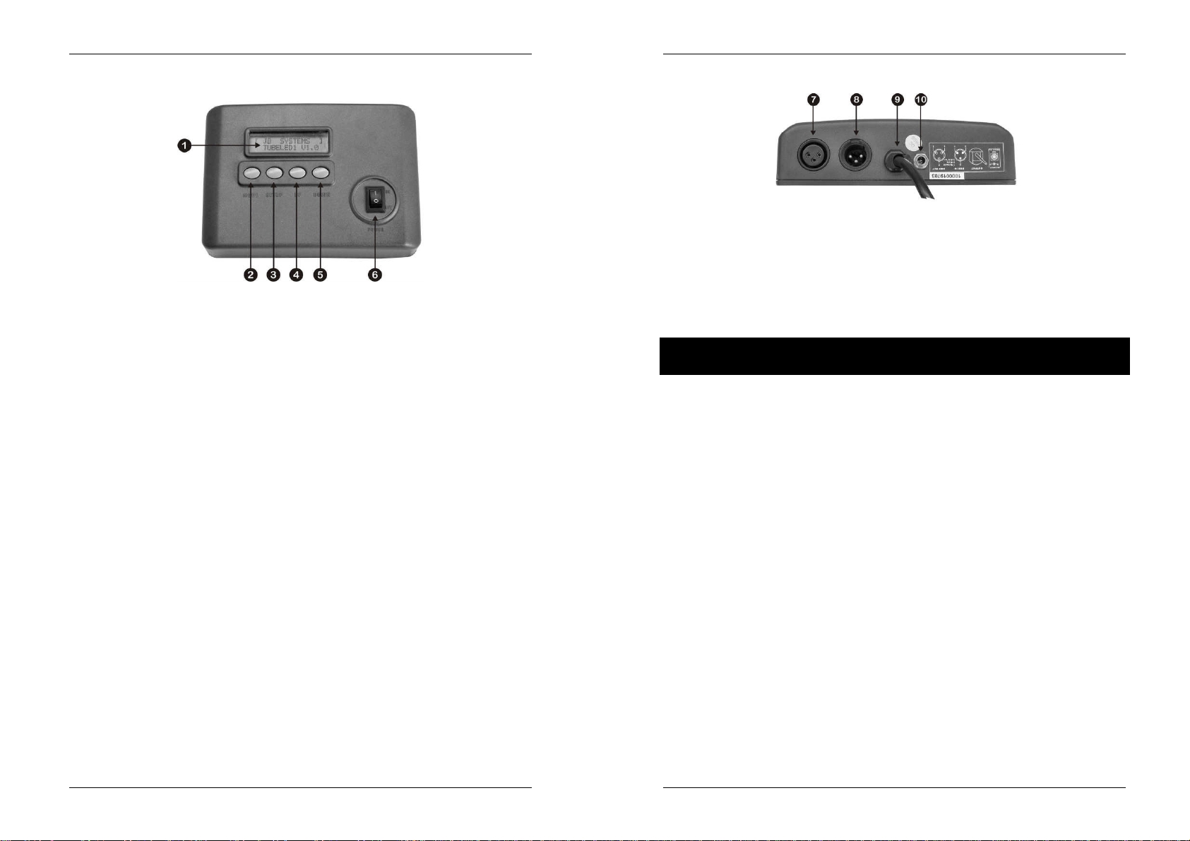
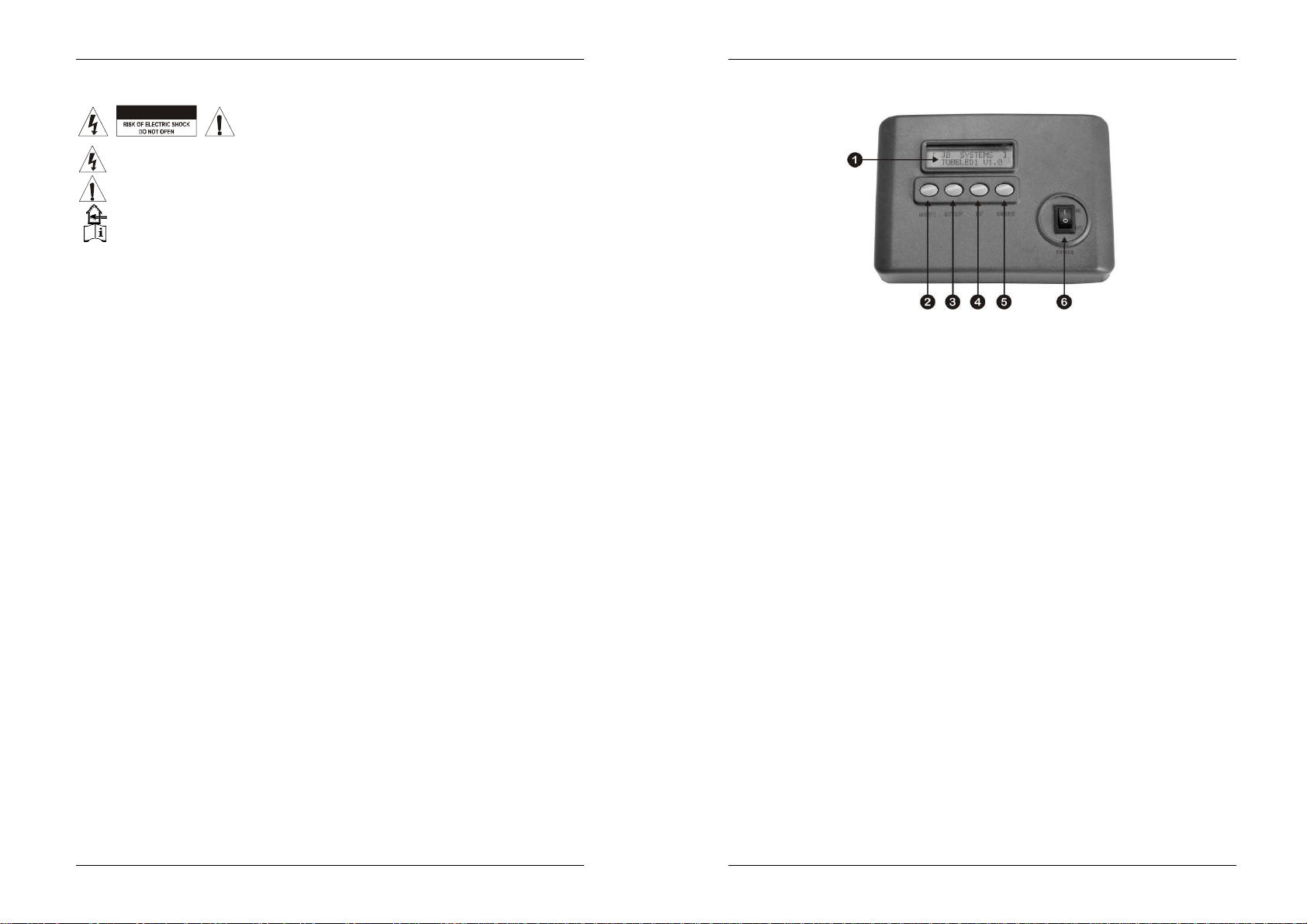
CONTROLS (FRONT)
1. LCD DISPLAY: shows you all necessaryinformationabout working mode, parameters etc.
2. MODE BUTTON: used to choose the desired working mode and patterns. The display shows
another function every time you push the button. Keep the button pressed if you want to browse
fasterthrough all possible modes. (see further forthe possible options tochoosefrom)
3. SETUP BUTTON: used to set the parameters of the selected mode or pattern. Almost every pattern
can have its own parameters. These parametersare savedfor everypatternindividually.
Interval: this is thewaiting time between two steps in a chase pattern.
With the UP/DOWN buttons you can select a value between 000 and 100. (000 = short
interval time * 100 = longer interval time)
Press SETUP again to confirm the selected parameter.
Speed: this is the speed of the chase pattern.
With the UP/DOWN buttons you can select a value between 000 and 100. (000 = low
speed * 100 = high speed)
Press SETUP again to confirm the selected parameter.
Flash: here you can select the strobe or flash rateof the TUBELED™.
With the UP/DOWN buttons you can select a value between 000 and 100.(000 = no strobe
function * 100 = high flash rate)
Press SETUP again to confirm the selected parameter.
Tube: used to set the number of TUBELED™ tubes connected to the controller. You only
need to setup the number of tubes once. Mostof the patterns won’t work properly when the
number of connected tubes doesn’t correspond to the selected number on the controller.
Remark:The setup function isnotavailableon allpatterns or workingmodes.
4. UP BUTTON: used to choose a higher value forthe selected parameter.
5. DOWN BUTTON: used to choose a lower value for the selectedparameter.
6. POWER ON/OFF: Used to switch the controller on and off. The last working mode is saved when
the controller is switched off.
CONNECTIONS (REAR)
7. DMX INPUT: The TUBELED™ controlleronly receives DMX signalsso it must beconnected as any
other light effect in the DMX line. The 3pin male XLR-connector receives instructions from any
universalDMX-controller.In the next chapter we explain how to set up the DMX addresses.
8. DMX OUTPUT: The 3pin female XLR-connector is used to connect the controller with the next unit
in the DMXchain.
9. TUBELED SIGNAL CABLE: connect this cable to the first led tube in the chain. Extra 5m or 10m
signal cable extensions are optionally available.
10. DC POWER INPUT: Used to connect the supplied 12V / 500mADC adapter to the controller.
INSTALLATION STEPS:
To be sure that the TUBELED™ system works properly you must follow the steps below every
time you change the number of tubes, put tubes at different locations or simply disconnect en
reconnect one or more tubes:
INSTALL ALL TUBES: Refer to the installation manual included with each TUBELED™ for proper
installation.
INSTALL THE CONTROLLER:
o Put the controllerin a suitable place. Eventually you can fix the controller to the wall.
o Connectthe suppliedDC adapterto the controller
o Connect the signal output to the signalinput of first led tube.
TEST CONNECTIONS: we will test the connection between the controller and the led tubes.
o Switch the controller on
o Use the MODE button to select “test mode”
o Press the SETUP button. (display shows “Connection OK if tubes are red”) As the display
SET THE NUMBER OF TUBELEDS: To be able to produce nice programs, the controller needs to
knowhow many tubeleds are connected.
Remark: If the number of connected tubes doesn’t match the number set on the controller, the
systemwillnot workproperly. Some tubeswill evennot workatall!
PROPER ADDRESSING: automatically sets the addresses of the connected tubes. Perform this
action alwayswhen you connect a different number of tubes:
At this point the setup is finished if you use the TUBELED™ system in standalone mode. Look further
on how to use the DMX capabilities.
states: if all led tubesare “red”, the connections are OK.
o Go to any of the “non static” patterns.
o Press the setup button until thedisplay shows “Tubes : 0000”
o Use the upand down buttons to set the exact numberof connected tubes.
o Press the setup button again to confirm.
o Use the MODE button to select “address mode”
o Press the SETUP button. During the initializing process the display shows “initializing addr.
Waiting…”When the initializingis done, the displayshows“OK! Address isdone”
JB SYSTEMS® 3/41 TUBELED™ CONTROLLER
JB SYSTEMS® 4/41 TUBELED™ CONTROLLER
Page 5
ENGLISH OPERATION MANUAL
ENGLISH OPERATION MANUAL
DMX512ADDRESSING: Before using theDMX capabilities you have to set the starting address:
o Use the MODE button to select “DMX512 Mode”
o Pressthe SETUP button.The display shows thecurrentDMX startingaddress.
o With the UP/DOWN buttons you can select the desired DMX starting address. (starting
addresses up to 255 can be selected)
o Press the SETUPbutton again to confirm the selected starting address.
FACTORY SETTINGS: As explained before you can set and save different parameters for all
patterns. You can set all parameters back to the factory settings. Attention: Note that all your
previoussettings will be lost:
o Use the MODE button to select “Factory settings” on the display.
o Press the SETUP button to load the factory settings. The display shows “OK! Setting is
done”
STANDALONE MODE:
This is the simplest way to operatethe TUBELED™ system.
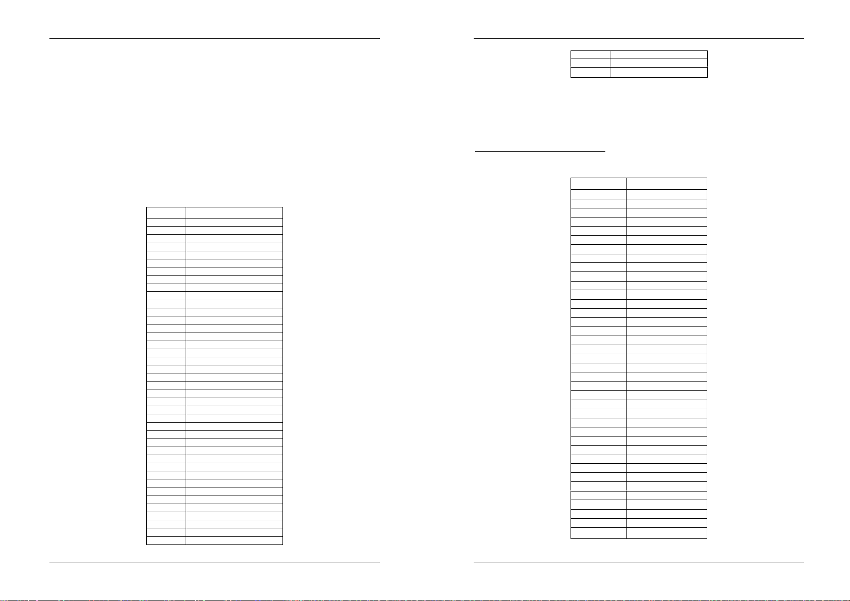
Use theMODE button to select the desired mode or patterns from the list below:
Number PATTERN / MODE
1 BLACKOUT
2 STATICRED
3 STATICGREEN
4 STATICYELLOW
5 STATIC BLUE
6 STATIC PURPLE
7 STATICCYAN
8 STATICWHITE
9 FAST CHANGE
10 SLOWFLOW 1
11 FAST FLOW 1
12 FAST FLOW 2
13 BLACKRUN 1
14 ROLLCHASE
15 ROLLCOLOR
16 COLOR1/4
17 COLOR1 1/4
18 COLOR1/2
19 COLORFLASH
20 B & W FLOW
21 R & G FLOW
22 G & B FLOW
23 R & B FLOW
24 R & G CHASE 1
25 R & G CHASE 2
26 R & B CHASE 1
27 R & B CHASE 2
28 R & W CHASE 1
29 R & W CHASE 2
30 B & G CHASE 1
31 B & G CHASE 2
32 W &G CHASE 1
33 W &G CHASE 2
34 RAINBOW CHASE 1
35 RAINBOW CHASE2
36 RAINBOW CHASE3
37 RAINBOW CHASE4
38 RAINBOW CHASE8
39 AUTO MODE
40 TESTMODE
41 ADDRESSMODE
42 Factory settingsload
43 DMX512MODE
Use the SETUP and UP/DOWN buttons to change the values of the pattern parameters. Refer to the
“CONTROLS (front)” section to read more about how to use thesebuttons.
DMX-512 MODE:
Before using the DMXcapabilities you haveto set the start address. See “installation steps”. There are
twodifferent ways to control the controller by DMX:
MODE1 – DMX PATTERN SELECTION:
Mode1 is active when the DMX value of channel1 is not zero!
Channel1 is used select one of thepreprogrammed patterns:
DMXValue Pattern
1~5 BLACKOUT
6~11 STATICRED
12~17 STATICGREEN
18~23 STATICYELLOW
24~29 STATIC BLUE
30~35 STATIC PURPLE
36~41 STATICCYAN
42~47 STATICWHITE
48~53 FAST CHANGE
54~59 SLOWFLOW1
60~65 FASTFLOWI
66~71 FAST FLOW2
72~77 BLACKRUNT
78~83 ROLLCHASE
84~89 ROLLCOLOR
90~95 COLOR1/4
96~101 COLOR1 1/4
102~107 COLOR1 ½
108~113 COLOR FLASH
114~119 B & W FLOW
120~125 R & G FLOW
126~131 G & B FLOW
132~137 R & B FLOW
138~143 R & G CHASE 1
144~149 R & G CHASE 2
150~155 R & B CHASE 1
156~161 R & B CHASE 2
162~167 R & W CHASE 1
168~173 R & W CHASE2
174~179 B & G CHASE 1
180~185 B & G CHASE 2
186~191 W &G CHASE 1
192~197 W&G CHASE 2
198~203 RAINBOW CHASE 1
204~209 RAINBOW CHASE 2
210~215 RAINBOW CHASE 3
216~221 RAINBOW CHASE 4
222~255 RAINBOW CHASE 8
JB SYSTEMS® 5/41 TUBELED™ CONTROLLER
JB SYSTEMS® 6/41 TUBELED™ CONTROLLER
Page 6

ENGLISH OPERATION MANUAL
FRANCAIS MODE D’EMPLOI
Channel2 is used to control the pattern speed:
Channel3 is used to control the interval time:
Channel4 is used to control the flash (strobe) rate:
Remark: note that channels 2 and 3 (speed and interval) have no effect on the blackout and static
colors(DMX valueforchannel1isbetween 1 and 47).
MODE2 – RGB COLOR MIXING:
Mode2 is active when the DMXvalue of channel1 is zero!
Channel1 is not used and must beset to zero.
Channel2 is used todim the RED coloredleds inside the tubes:
Channel3 is used to dimthe GREEN colored leds insidethe tubes:
Channel4 is used todim the BLUE coloredleds inside the tubes:
DMXvalue = 000 Speed = 0
DMXvalue = 255 Speed = maximum
DMXvalue = 000 Interval time = 0
DMXvalue = 255 Interval time = maximum
DMXvalue = 000 Interval time = 0
DMXvalue = 255 Interval time = maximum
DMXvalue = 000 no red light output
DMXvalue = 255 maximumred light output
DMXvalue = 000 no greenlight output
DMX value = 255 maximumgreen lightoutput
DMXvalue = 000 no bluelight output
DMXvalue = 255 maximumblue light output
SPECIFICATIONS
Mains Input: DC Adapter230V/50Hz 12Vdc/ 500mA
Preprogrammedpatterns: 38
Max. number of tubes: up to 4000pcs.
DMX connections: 3pinXLR male / female
DMXaddressing: 000 to255
Power consumption: <1.5Watt
Size: 180 x 125 x 49mm
Weight: 0.4kg
You can download the latest version of thisuser manualon our website:www.beglec.com
Every information is subjectto change withoutprior notice
MODE D’EMPLOI
Nous vous remercions d’avoir acheté ce produit JB Systems®. Veuillez lire ce mode d’emploi
attentivement afin de pouvoir exploitercorrectement toutes lespossibilités de cet appareil
Le système JB SystemsTUBELED™ est composé des élémentssuivants:
Lestubes TUBELED™ d’1m de long: a connecter au contrôleur.
LecontrôleurTUBELED™:commandelestubes connectés.
Descâbles rallonge du Signal: 5m ou 10m.
Descâbles rallonge d’alimentation: 5m, 10m ou 20m.
Ce mode d’emploi explique uniquementcommentutiliser le contrôleur.
CARACTERISTIQUES
Contrôleurspécifiquepour commanderles tubes TUBELED™ (non compris)
Peut commander jusqu’à 4000 tubes, ne nécessite pas de modules d’alimentation
supplémentaires.
38programmespréprogrammés
Lafonction Auto parcourt automatiquement tous lesprogrammes.
Sélectiondu programme par DMX512:
o Canal1: choix des programmes
o Canal2: contrôlede la vitesse
o Canal3: temps d’intervalle
o Canal4:vitessestroboscope/flash
Mixage des couleurs RVB, contrôlé par DMX512 (créez vos propres couleurs):
o Canal1: n’est pas utilisé(réglé sur zéro)
o Canal2: atténuation de la couleurrouge
o Canal3: atténuationde la couleur verte
o Canal4: atténuationde la couleurbleue
Fonction stroboscopiqueréglable
Vitesse et temps d’intervalle réglablepour la plupart des programmes
Beau boîtier en plastique qui peut être fixé au mur
Fonction de sauvegarde automatique: sauvegarde du mode de fonctionnement pour tous les
programmes(patterns)individuellement.
Convient parfaitement pour: des magasins, des étalages, l’éclairage architectural, la décoration
intérieure et extérieure,les clubs, tavernes, disco mobile,dans les structures de pont, …
JB SYSTEMS® 7/41 TUBELED™ CONTROLLER
AVANT L’UTILISATION
Contrôlez le contenu:
Vérifiezsi la boitecontient leséléments suivants:
LecontrôleurTUBELED™
Adaptateur d’alimentationDC 12V 500mA
Mode d’emploi
JB SYSTEMS® 8/41 TUBELED™ CONTROLLER
Page 7
FRANCAIS MODE D’EMPLOI
FRANCAIS MODE D’EMPLOI
INSTRUCTIONS DE SECURITE:
CAUTION
uniquementà des techniciensqualifiés.
La flèche dans un triangle met l'utilisateur en garde contre la présence de haute tension sans
isolationdans l'appareil qui peut causer un risque d'électrocution.
Un point d'exclamation dans un triangle prévient de la présence d'instructions de
fonctionnement et de maintenance se trouvant dans le manuel, fourni avec l'appareil.
Ce symbole signifie: uniquement pour usageà l'intérieur
Ce symbole signifie : Lire le mode d’emploi.
Afin d’éviter tout risque d’incendie ou de choc électrique, ne pas exposer cet appareil à la pluie ou
l’humidité.
Pour éviter la formation de condensation à l’intérieur de l’appareil, patientez quelques minutes pour
laisserl’appareil s’adapter à la température ambiantelorsqu’il arrive dans unepièce chauffée après le
transport. La condensation empêche l’unité de fonctionner en performance optimale et peut même
causerdes dommages.
Cette unitéest destinée à une utilisationà l’intérieuruniquement.
Ne pas insérer d’objetmétalliqueou verser un liquidedans l’appareil. Aucun objet rempli de liquides,
tels que des vases, ne peut être placé sur cet appareil. Risque de choc électrique ou de
dysfonctionnement. Si un corps étranger est introduit dans l’unité, déconnectez immédiatement de la
sourced’alimentation.
Aucune source deflamme nue, telle que les bougies allumées,ne peut être placée sur l'appareil.
Ne pas couvrir les ouverturesde ventilation, unrisque de surchauffeen résulterait.
Ne pas utiliserdans un environnement poussiéreux et nettoyezl’unitérégulièrement.
Ne pas laisser l’unité à portée des enfants.
Les personnes non expérimentéesne doivent pas utilisercet appareil.
La température ambiante maximum d’utilisationde l’appareil est de 40°C. Ne pas l’utiliserau-delà de
cette température.
Débranchez toujours l’appareil si vous ne l’utilisez pas de manière prolongée ou avant
d’entreprendredesréparations.
Les installations électriques ne peuvent être faites que par du personnel qualifié et conformément aux
régulations desécurité électriqueet mécaniqueenvigueur dans votrepays.
Assurez-vous que la tension d’alimentation de la source d’alimentation de la zone dans laquelle vous
vous trouvezne dépasse pas celui indiqué à l’arrière de l’appareil.
La prise sera toujours accessible pour quele cordonsecteur puisseêtre enlevé à chaque moment.
Le cordon d’alimentation doit toujours être en condition parfaite. Mettez immédiatement l’unité hors
tensionsi le cordon estécrasé ou endommagé.
Ne laissez jamais le cordond’alimentationentrer en contact avecd’autres câbles !
Utilisez toujours les câbles appropriéset certifiés lorsquevous installez l’unité.
Pour éviter tout choc électrique, ne pas ouvrir l’appareil. En dehors du fusible principal, il n’y a pas de
pièces pouvant être changées par l’utilisateur à l’intérieur.
Ne jamais
endommagépar un fusible de mêmetype et ayant les mêmes spécifications électriques !
En cas de problèmes de fonctionnement sérieux, arrêtez toute utilisation de l’appareil et contactez
votrerevendeur immédiatement.
Utilisez l’emballage d’origine si l’appareil doit être transporté.
Pour des raisons de sécurité, il est interdit d’apporter toute modification à l’unité non spécifiquement
autoriséepar les parties responsables.
réparer ou court-circuiter un fusible. Remplacez
ATTENTION: afin de réduire le risque d’électrocution, n’enlevez
jamais lecouvercle de l’appareil.Il n’y a aucune pièce à l’intérieur de
l’appareil quevous pouvezremplacervous-même. Confiez l’entretien
systématiquement
un fusible
CONTROLES (FACE AVANT)
1. ECRAN LCD: affiche toutes les informations utiles du mode de fonctionnement, des paramètres,
etc.
2. Touche MODE: est utilisée pour sélectionner le mode de fonctionnement et les programmes
(patterns) désirés. L’écran affiche une autre fonction chaque fois que vous appuyez sur la touche.
Tenez la touché enfoncée si vous désirez parcourir plus rapidement tous les modes de
fonctionnement qui sont disponibles. (voyez plus loin pour voirtoutes lesoptions possibles)
3. Touche SETUP: est utilisée pour régler les paramètres du mode de fonctionnement ou du
programme sélectionné. A peu près chaque programme peut avoir ses propres paramètres. Ces
paramètressont sauvegardés pour chaque programme(pattern) séparément.
Interval: ceci est le temps d’attente entre deux pas dans un programme du type chenillard
(chase).
A l’aide des touches UP/DOWN vous pouvez sélectionner une valeur située entre 000 et
100. (000 = courte duréed’intervalle * 100 = longue duréed’intervalle)
Appuyez à nouveau sur la touche SETUP pour confirmerle paramètresélectionné.
Speed: ceci est lavitesse du programme chenillard (chasepattern).
A l’aide des touches UP/DOWN vous pouvez sélectionner une valeur située entre 000 et
100. (000 = lent * 100 = rapide)
Appuyez à nouveau sur la toucheSETUP pour confirmerle paramètresélectionné.
Flash: ici vous pouvez sélectionner la fréquence du stroboscope ou du flash du
TUBELED™.
A l’aide des touches UP/DOWN vous pouvez sélectionner une valeur située entre 000 et
100. (000 = pas de fonction stroboscopique * 100 = haute fréquence du flash)
Appuyez à nouveau sur la toucheSETUP pour confirmerle paramètre sélectionné.
Tube: est utilisé pour spécifier lenombre de tubes TUBELED™ qui sont connectés à votre
contrôleur. Vous ne devez spécifier le nombre de tubes qu’une seule fois. La plupart des
programmes ne fonctionneront pas correctement si le nombre de tubes connectés ne
correspondpas au nombre sélectionné dans le contrôleur.
Remarque: La fonction setup n’est pas disponible pourtous lesprogrammes ou tous lesmodes de
fonctionnement.
4. Touche UP: est utilisée pour attribuerune plus grande valeurau paramètre sélectionné.
5. ToucheDOWN: estutilisée pour attribuer uneplus petite valeur au paramètre sélectionné.
6. POWER ON/OFF: Est utilisé pour allumer ou éteindre le contrôleur. Quand vous éteignez le
contrôleur,le dernier mode de fonctionnement sera sauvegardéautomatiquement.
JB SYSTEMS® 9/41 TUBELED™ CONTROLLER
JB SYSTEMS® 10/41 TUBELED™ CONTROLLER
Page 8

FRANCAIS MODE D’EMPLOI
FRANCAIS MODE D’EMPLOI
CONNECTIONS (ARRIERE)
7. ENTREE DMX: Le contrôleur TUBELED™ reçoit uniquement des signaux DMX et doit donc être
connecté comme chaque autre effet dans la ligne DMX. Le connecteur XLR male à 3 pôles reçoit
les instructions de n’importe quel contrôleur DMX universel. Au chapitre suivant nous-vous
expliquonscomment attribuer les adresses DMX.
8. SORTIE DMX: Le connecteur XLR femelle à 3 pôles est utilisé pour connecter le contrôleur au
prochain appareil dans la chaîneDMX.
9. CABLE DU SIGNAL TUBELED: connectez ce câble au premier tube Led dans la chaîne. Des
câbles rallonge de 5m ou 10m sontdisponibles en option.
10. DC POWER INPUT: Est utilisé pour connecter l’adaptateur d’alimentation 12V / 500mA DC, fourni
avec le contrôleur.
INSTALLATION PAS PAR PAS:
Pour être sûr que votre installation TUBELED™ fonctionne correctement vous devez suivre les
étapes ci-dessous chaque fois que vous changez le nombre de tubes, changez les tubes de
place ou simplement débranchez et rebranchez1 ou plusieurs tubes:
INSTALLEZ TOUS LES TUBES: Référez-vous au manuel d’installation fourni avec chaque
TUBELED™ afin d’assurer une installation correcte.
INSTALLEZ LE CONTROLEUR:
o Installez le contrôleur à un endroit approprié. Vous pouvez éventuellement fixer le
contrôleur au mur.
o Connectezl’adaptateurd’alimentation au contrôleur.
o Connectezla sortie du signalà l’entrée signal du premiertube led.
TESTEZ LES CONNEXIONS: nous testeronsla connexion entre le contrôleur et les tubesled.
o Allumezle contrôleur
o Utilisezla touche MODE pour sélectionner “test mode”
o Appuyezsur la touche SETUP. (l’écran affiche “Connection OK if tubes are red”) Si cela est
SPECIFIEZ LE NOMBRE DE TUBELEDS: Pour être capable de produire de beaux programmes, le
contrôleur doit savoir combiende tubeleds sont reliesensemble.
Remarque: Si le nombre de tubes connectés ne correspond pas au nombre introduit dans le
contrôleur, le système ne fonctionnera pas correctement. Certains tubes peuvent même ne pas
fonctionner du tout!
ADRESSAGE ADEQUAT: règle automatiquementles adresses des tubesconnectés. Exécutezcette
actionchaque fois que vous connectezun nombre différent de tubes:
A ce stade, l’installation est terminée si vous désirez utilisez le système TUBELED™ de façon
autonome.Voyezplus loin commentutiliser les possibilités DMX.
affiché et que tous les tubes sonteffectivementrouges, lesconnexions sont correctes.
o Choisissez un programme “non statique”.
o Appuyezsur la touchesetup jusqu’à ceque l’écran affiche“Tubes: ….”
o Utilisezles touches up etdown pour spécifier lenombre exact de tubes connectés
o Appuyez à nouveausur la touche setup pourconfirmer.
o Utilisezla touche MODE pour sélectionner“address mode”
o Appuyez sur la touche SETUP. Pendant le processus d’initialisation, l’écran affiche
“initializing addr. Waiting…” Quand l’initialisation est terminée, l’écran affiche “OK! Address
is done”(adressageterminé)
ADRESSAGEDMX512: Avant de pouvoir exploiter les possibilités DMX vous devez définir l’adresse
de départ:
o Utilisezla touche MODEpour sélectionner “DMX512 Mode”
o Appuyezsur la touche SETUP.L’écran affiche l’adresse de départDMX actuel.
o Vous pouvez sélectionner l’adresse DMX de départ désirée en utilisant les touches
UP/DOWN. (une adressede départjusqu’à 255 peutêtre sélectionnée)
o Appuyez à nouveau surla touche SETUP pour confirmer l’adresse de départsélectionnée.
REGLAGES D’USINE: Comme expliqué auparavant, vous pouvez régler et sauvegarder différents
paramètres pourtous les programmes. Vous pouvez également réinstaller tous les paramètres selon
le réglage d’usine. Attention: tousvos réglagesprécédents serontperdus:
o Utilisezla touche MODE pour sélectionner“Factorysettings” sur l’écran.
o Appuyez sur la touche SETUP pour charger les réglages d’usine. L’écran affiche “OK!
Settingis done”
FONCTIONNEMENT AUTONOME:
Ceci est la façon la plus simple pour fairefonctionner lesystème TUBELED™ .
Utilisez la touche MODE pour sélectionner le mode de fonctionnement ou le programme désiré de la
liste ci-dessous:
Number PATTERN / MODE
1 BLACKOUT
2 STATICRED
3 STATICGREEN
4 STATICYELLOW
5 STATIC BLUE
6 STATIC PURPLE
7 STATICCYAN
8 STATICWHITE
9 FAST CHANGE
10 SLOWFLOW 1
11 FAST FLOW 1
12 FAST FLOW 2
13 BLACKRUN 1
14 ROLLCHASE
15 ROLLCOLOR
16 COLOR1/4
17 COLOR1 1/4
18 COLOR1/2
19 COLORFLASH
20 B & W FLOW
21 R & G FLOW
22 G & B FLOW
23 R & B FLOW
24 R & G CHASE 1
25 R & G CHASE 2
26 R & B CHASE 1
27 R & B CHASE 2
28 R & W CHASE 1
29 R & W CHASE 2
30 B & G CHASE 1
31 B & G CHASE 2
32 W &G CHASE 1
33 W &G CHASE 2
34 RAINBOW CHASE 1
35 RAINBOW CHASE2
36 RAINBOW CHASE3
37 RAINBOW CHASE4
JB SYSTEMS® 11/41 TUBELED™ CONTROLLER
JB SYSTEMS® 12/41 TUBELED™ CONTROLLER
Page 9

FRANCAIS MODE D’EMPLOI
FRANCAIS MODE D’EMPLOI
38 RAINBOW CHASE8
39 AUTO MODE
40 TESTMODE
41 ADDRESSMODE
42 Factory settingsload
43 DMX512MODE
Utilisez les touches SETUP et UP/DOWN pour changer la valeur des paramètres du programme.
Référez-vous au chapitre “CONTROLES (faceavant)” pour savoir comment utiliserces touches.
FONCTIONNEMENT DMX-512:
Avant d’utiliser les possibilités DMX vous devez régler l’adresse de départ. Voir “installation pas par
pas”. Il y a 2 différentes façons pour commander le contrôleur parDMX :
MODE1 – SELECTIONDES MODELESPAR DMX:
Mode1 estactif quand la valeur DMX du canal 1 n’est pas réglée sur zéro!
Canal1 estutilise poursélectionner undes programmes préprogrammés:
DMXValue Pattern
1~5 BLACKOUT
6~11 STATICRED
12~17 STATICGREEN
18~23 STATICYELLOW
24~29 STATIC BLUE
30~35 STATIC PURPLE
36~41 STATICCYAN
42~47 STATICWHITE
48~53 FAST CHANGE
54~59 SLOWFLOW1
60~65 FASTFLOWI
66~71 FAST FLOW2
72~77 BLACKRUNT
78~83 ROLLCHASE
84~89 ROLLCOLOR
90~95 COLOR1/4
96~101 COLOR1 1/4
102~107 COLOR1 ½
108~113 COLOR FLASH
114~119 B & W FLOW
120~125 R & G FLOW
126~131 G & B FLOW
132~137 R & B FLOW
138~143 R & G CHASE 1
144~149 R & G CHASE 2
150~155 R & B CHASE 1
156~161 R & B CHASE 2
162~167 R & W CHASE 1
168~173 R & W CHASE2
174~179 B & G CHASE 1
180~185 B & G CHASE 2
186~191 W &G CHASE 1
192~197 W&G CHASE 2
198~203 RAINBOW CHASE 1
204~209 RAINBOW CHASE 2
210~215 RAINBOW CHASE 3
216~221 RAINBOW CHASE 4
222~255 RAINBOW CHASE 8
Canal2 est utilise pour contrôler la vitesse du programme:
Canal3 est utilisé pour contrôlerle temps d’intervalle:
Canal4 est utilisé pour contrôler la fréquence du flash (stroboscope):
Remarque: les canaux 2 et 3 (vitesse et intervalle) n’ont aucun effet sur le black-out et les couleurs
statiques (valeur DMXpour le canal1 est situéentre 1 et 47).
MODE2 – MIXAGE DES COULEURS RVB:
Mode2 estactif quand la valeur DMX du canal 1 est zéro!
Canal1 n’est pas utilise et doitêtre misà zéro.
Canal2 est utilisé pour atténuer les leds de couleur ROUGE à l’intérieur des tubes:
Canal3 est utilisé pour atténuer les leds de couleur VERTE à l’intérieur des tubes:
Canal4 est utilisé pour atténuer les leds de couleur BLEUE à l’intérieurdes tubes:
ValeurDMX = 000 Vitesse = 0
ValeurDMX = 255 Vitesse = maximale
ValeurDMX = 000 Temps d’intervalle= 0
ValeurDMX = 255 Temps d’intervalle= maximal
ValeurDMX = 000 Temps d’intervalle= 0
ValeurDMX = 255 Temps d’intervalle= maximal
ValeurDMX = 000 pas de lumière rouge
ValeurDMX = 255 niveau maximal dela lumière rouge
ValeurDMX = 000 pas de lumière verte
ValeurDMX = 255 niveau maximal dela lumière verte
ValeurDMX = 000 pas de lumière bleue
ValeurDMX = 255 niveau maximal dela lumière bleue
CARACTERISTIQUES
Alimentation: DC Adapter230V/50Hz 12Vdc/ 500mA
Programmespréprogrammés: 38
Nombre Max. de tubes: jusqu’à4000pcs.
ConnecteursDMX: 3pin XLR male / femelle
AdressageDMX: 000 à 255
Consommation: <1.5Watt
Dimensions: 180 x 125 x 49mm
Poids: 0.4 kg
Chacune de ces informationspeut être modifiée sans avertissementpréalable.Vouspouvez
télécharger la dernière version de ce moded’emploide notre site Web: www.beglec.com
JB SYSTEMS® 13/41 TUBELED™ CONTROLLER
JB SYSTEMS® 14/41 TUBELED™ CONTROLLER
Page 10

NEDERLANDS GEBRUIKSAANWIJZING
NEDERLANDS GEBRUIKSAANWIJZING
GEBRUIKSAANWIJZING
Wij danken u voor de aankoop van dit JB Systems®product. Om voordeel te halen uit alle
mogelijkheden die dit toestelbiedt, raden wij U aan dezehandleiding zeer aandachtig te lezen.
HetJB Systems TUBELED™ systeem bestaat uit de volgende componenten:
De1m langeTUBELED™ buizen: moeten verbonden worden met decontroller.
DeTUBELED™ controller:stuurt de aangesloten led buizen.
Signaalverlengkabels:5m of 10m.
Verlengkabels voor de voeding: 5m, 10mof 20m.
Deze gebruiksaanwijzinglegt u enkel de functies uit van de controller.
EIGENSCHAPPEN
Specifiekecontroller voorhetaansturen van de TUBELED™ buizen(niet inbegrepen)
Controleert tot 4000 buizen, geen extrapower boosters nodig.
38voorgeprogrammeerdepatronen
Auto mode overlooptautomatisch alle patronen
Patroon selectievia DMX512:
o Kanaal1:keuze van de patronen
o Kanaal2: snelheidscontrole
o Kanaal 3: intervaltijd
o Kanaal 4: strobe/flits frequentie
RGBkleurenmix, gestuurd viaDMX512 (maak uw eigen kleuren):
o Kanaal 1: niet gebruikt (staatop nul)
o Kanaal 2: dimmen van de rode kleur
o Kanaal 3: dimmen van de groene kleur
o Kanaal 4: dimmen van de blauwe kleur
Regelbarestroboscoopfunctie
Regelbaresnelheid en intervaltijd voor demeeste patronen
Mooie plastiekenbehuizing die aan de muur kan bevestigd worden
Auto save functie: bewaartde laatste werkmodus voor alle patronen afzonderlijk.
Ideaal voor een gebruik in: winkels, uitstalramen, gevelverlichting, binnen en buiten versiering,
clubs, pubs,mobieleDJs, brugstructuren,…
VÓÓR GEBRUIK
Controleer de inhoud:
Kijk na of de verpakking volgende onderdelen bevat:
TUBELED™ controller
DC12V 500mAVoedingsadapter
Gebruiksaanwijzing
VEILIGHEIDSVOORSCHRIFTEN:
CAUTION
De bliksempijl die zich in een gelijkbenige driehoek bevindt is bedoeld om u te wijzen op het
gebruik of de aanwezigheid van niet-geïsoleerde onderdelenmet een “gevaarlijkespanning” in
het toestel die voldoende kracht heeft om een risicovan elektrocutiein te houden.
Het uitroepteken binnende gelijkbenige driehoek is bedoeld om degebruiker erop te wijzen dat
er in de meegeleverde literatuur belangrijke gebruik en onderhoudsinstructies vermeld staan
betreffendedit onderdeel.
Dit symbool betekent:het apparaat magenkelbinnenhuis worden gebruikt.
Dit symbool betekent: Lees dehandleiding!
Stel dit apparaat niet bloot aan regen of vocht, dit om het risico op brand en elektrische schokken te
voorkomen.
Om de vorming van condensatie binnenin te voorkomen, laat het apparaat aan de
omgevingstemperatuur wennen wanneer het, na het transport, naar een warm vertrek is
overgebracht. Condensatie kan het toestel soms verhinderen perfect te functioneren. Het kan soms
zelfsschade aan het apparaattoebrengen.
Gebruik dit apparaatuitsluitend binnenshuis.
Plaats geen stukken metaal en mors geen vocht binnen in het toestel om elektrische schokken of
storing te vermijden. Objecten gevuld met water, zoals bvb. Vazen, mogen op dit apparaat worden
geplaatst. Indien er toch een vreemd voorwerp of water in het apparaat geraakt, moet U het direct
van het lichtnetafkoppelen.
Open vuur,zoals brandende kaarsen,mogen niet op het apparaat geplaatst worden.
Bedek geen enkeleventilatieopening om oververhitting tevermijden.
Zorg dat het toestel niet in een stoffigeomgeving wordt gebruikt en maak hetregelmatigschoon.
Houdhet apparaatuit de buurtvan kinderen.
Ditapparaatmag niet door onervaren personen bediend worden.
De maximum veilige omgevingstemperatuur is 40°C. Gebruik het apparaat dus niet bij hogere
temperaturen.
Trek altijd de stekker uit wanneer het apparaat gedurende langere tijd niet wordt gebruikt of alvorens
metde onderhoudsbeurt te beginnen.
De elektrische installatie behoort uitsluitend uitgevoerd te worden door bevoegd personeel, volgens
de in uw land geldende regels betreffendeelektrische en mechanische veiligheid.
Controleer dat de beschikbare spanning niet hoger is dan die aangegeven op de achterzijdevan het
toestel.
Het stopcontact zal steeds vrij toegankelijk blijven zodat de stroomkabel op elk moment kan worden
uitgetrokken.
De elektrische kabel behoort altijd in uitstekende staat te zijn. Zet het apparaat onmiddellijk af als de
elektrischekabelgekneusd of beschadigd is.
Laat de elektrische draad nooit in contact komen met andere draden.
Om elektrische schokken te voorkomen, moet U debehuizing niet openen. Afgezien van de zekering
zitten er geen onderdelen in diedoor de gebruikermoetenworden onderhouden.
Repareer nooit een zekering en overbrug de zekeringhouder nooit. Vervang een beschadigde
zekering steeds door een zekering van hetzelfde type en met dezelfdeelektrische kenmerken.
Ingeval van ernstige problemen met het bedienen van het toestel, stopt U onmiddellijk het gebruik
ervan. Contacteer uwdealer voor een eventuele reparatie.
Gebruik best de originele verpakking als het toestelvervoerd moet worden.
Om veiligheidsredenen is het verboden om ongeautoriseerde modificaties aan het toestel aan te
brengen.
WAARSCHUWING: Om het risico op elektrocutie zoveel mogelijk te
vermijden mag u nooit de behuizing verwijderen. Er bevinden zich
geen onderdelen in het toestel die u zelf kan herstellen. Laat de
herstellingen enkel uitvoerendoor een bevoegde technicus.
JB SYSTEMS® 15/41 TUBELED™ CONTROLLER
JB SYSTEMS® 16/41 TUBELED™ CONTROLLER
Page 11

NEDERLANDS GEBRUIKSAANWIJZING
NEDERLANDS GEBRUIKSAANWIJZING
CONTROLES (VOORKANT)
1. LCD DISPLAY: geeft al de nodige informatieweer betreffende de werkmodus, parameters enz.
2. MODE TOETS: wordt gebruikt om de gewenste werkmodus en patronen te kiezen. Telkens u op de
toets drukt zal de display een andere functie weergeven. Houd deze toets ingedrukt als u sneller
alle mogelijkheden wil overlopen. (zie verdervoor alle keuzemogelijkheden)
3. SETUP TOETS: wordt gebruikt om de parameters in te stellen van de gekozen modus of patroon.
Bijna elke patroon kan zijn eigen parameters toegewezen krijgen. Deze parameters worden voor
elke patroon afzonderlijkbewaard.
Interval: dit is de wachttijdtussen 2 stappen in een chase patroon.
Met de UP/DOWN toetsen kunt u een waarde kiezen tussen 000 en 100. (000 = korte
intervaltijd * 100 = langeintervaltijd)
Druk weerop SETUP om de geselecteerdeparameterte bevestigen.
Speed: dit is de snelheidvan het chasepatroon.
Met de UP/DOWN toetsen kunt u een waarde kiezen tussen 000 en 100. (000 = traag *
100 = snel)
Druk weerop SETUP om de geselecteerdeparameterte bevestigen.
Flash: hier kunt u de strobe of flitsfrequentie kiezen van de TUBELED™.
Met de UP/DOWN toetsen kunt u een waarde kiezen tussen 000 en 100. (000 = geen
strobe functie * 100 = hoge flitsfrequentie)
Druk weerop SETUP om de geselecteerdeparameterte bevestigen.
Tube: wordt gebruikt om het aantal TUBELED™ buizen in te stellen die verbonden zijn met
de controller. U moet het aantal buizen slechts één keer instellen. De meeste patronen
zullen niet correct werken als het aantal verbonden buizen niet overeenstemt met het
gekozen getal in de controller.
Opmerking:De setup functie is niet beschikbaar vooralle patronenofwerkmodi.
4. UP TOETS: wordt gebruikt om een hogere waarde in te stellen voor de gekozen parameter.
5. DOWN TOETS: wordt gebruikt om een lagere waardein te stellen voor de gekozen parameter.
6. POWER ON/OFF:Wordt gebruikt om de controller aan of uit te zetten. De laatste werkmodus wordt
behouden als de controller uitgezetwordt.
VERBINDINGEN (ACHTERKANT)
7. DMX INGANG: De TUBELED™ controller ontvangt enkel DMX signalen en moet bijgevolg
aangesloten worden zoals om het even welk ander lichteffect in de DMX lijn. De mannelijke 3pins
XLR aansluiting ontvangt instructies van om het even welke universele DMX controller. In het
volgende hoofdstuk leggen wij u uit hoe u de DMXadressen moetinstellen.
8. DMX UITGANG: De vrouwelijke3pins XLR aansluiting wordt gebruikt om de controller te verbinden
met het volgende toestel in de DMX keten.
9. TUBELED SIGNAALKABEL: verbind deze kabel met de eerste led tube in de keten. Extra 5m of
10m signaalverlengkabels zijn in optie verkrijgbaar.
10. DC POWER INGANG: wordt gebruikt om de meegeleverde12V / 500mA DC voedingsadapter aan
te sluiten aan de controller.
INSTALLATIESTAPPEN:
Om een correcte werking van het TUBELED™ systeem te verzekeren moet u volgende stappen
uitvoeren, telkens u het aantal buizen wijzigt, buizen van plaats verwisselt of gewoon 1 of
meerdere tubes losmaakt en terug aansluit:
INSTALLEER ALLE BUIZEN: Raadpleeg de installatiehandleiding die bij elke TUBELED™
bijgevoegd is voor een correcteplaatsing.
INSTALLEER DE CONTROLLER:
o Installeerde controller op een gepaste plaats. U kunt de controller eventueel aan de muur
bevestigen.
o Verbind de meegeleverde DC adapter met de controller
o Verbind de signaaluitgang metde signaalingang van de eerste led buis.
TEST DE AANSLUITINGEN: we zullen de aansluitingen tussen de controller en de led tubes
controleren.
o Schakel de controller aan
o Gebruik de MODE toets en kies “test mode”
o Druk op de SETUP toets. (displaytoont: “Connection OK if tubes are red”) Wanneer dit op
STEL HET AANTAL TUBELEDS IN: Om leuke programma’s te kunnen produceren moet de
controllerweten hoeveel tubeleds er aangesloten zijn.
Opmerking: Als het aantalverbondenbuizen niet overeen stemt met hetaantal dat ingesteld is in de
controller, dan zal het systeem niet correct werken. Sommige buizen zullen zelfs helemaal niet
werkenl!
ADRESSERING: De adressen van de verbonden buizen wordt automatisch ingesteld. Voer deze
actie steeds uit wanneer u een verschillend aantal buizen aansluit op de controller:
de displayweergegeven wordt en alle buizen zijn rood, dan zijn alle aansluitingen OK.
o Ga naar een van de “niet statische” patronen.
o Druk op de setup toets tot de display “Tubes: 0000” weergeeft
o Gebruik de up en down toetsenom het exacte aantal aangesloten buizen in te stellen.
o Druk weer op de setup toets om te bevestigen.
o Gebruik de MODE toetsen kies “address mode”
JB SYSTEMS® 17/41 TUBELED™ CONTROLLER
JB SYSTEMS® 18/41 TUBELED™ CONTROLLER
Page 12

NEDERLANDS GEBRUIKSAANWIJZING
NEDERLANDS GEBRUIKSAANWIJZING
o Druk op de SETUP toets. Tijdens het initialisatie proces geeft de display “initializing addr.
Waiting…” weer. Wanneer de initialisatie klaar is geeft de display “OK! Address is done”
De set-up is nu klaar als u het TUBELED™ systeem wilt gebruiken in standalone mode. Zie verder
voor het gebruik van de DMX mogelijkheden.
DMX512 ADRESSERING: Voor u de DMX mogelijkheden gebruikt moet u eerst het startadres
instellen:
FABRIEKSINSTELLING: Zoals eerder werd uitgelegd kunt u verschillende parameters voor alle
patronen instellen en opslaan. U kunt al deze parameters terugbrengen naar de originele
fabrieksinstelling. Opgelet: Al uwpersoonlijke instellingen zullenverloren gaan:
weer.
o Gebruik de MODE toets om “DMX512 Mode” te selecteren
o Druk op de SETUP toets. De displaygeeft het huidigeDMX startadres weer.
o Met de UP/DOWN toetsen kunt u het gewenste DMX startadres kiezen. (u kunt een
startadreskiezen tot 255)
o Druk terug op de SETUP toets om hetgekozen startadres te bevestigen.
o Gebruik de MODE toets om “Factory settings” te kiezen op de display.
o Druk op de SETUP toets om de fabrieksinstellingen op te laden. De display geeft “OK!
Setting is done” weerals de fabrieksinstellingenopgeladenzijn.
STANDALONE MODE:
Dit is de eenvoudigstemanier om met het TUBELED™ systeemte werken.
Gebruik de MODE toets om degewenste werkmodus of patroon uit deonderstaande lijst te kiezen:
Number PATROON / MODE
1 BLACKOUT
2 STATICRED
3 STATICGREEN
4 STATICYELLOW
5 STATIC BLUE
6 STATIC PURPLE
7 STATICCYAN
8 STATICWHITE
9 FAST CHANGE
10 SLOWFLOW 1
11 FAST FLOW 1
12 FAST FLOW 2
13 BLACKRUN 1
14 ROLLCHASE
15 ROLLCOLOR
16 COLOR1/4
17 COLOR1 1/4
18 COLOR1/2
19 COLORFLASH
20 B & W FLOW
21 R & G FLOW
22 G & B FLOW
23 R & B FLOW
24 R & G CHASE 1
25 R & G CHASE 2
26 R & B CHASE 1
27 R & B CHASE 2
28 R & W CHASE 1
29 R & W CHASE 2
30 B & G CHASE 1
31 B & G CHASE 2
32 W &G CHASE 1
33 W &G CHASE 2
34 RAINBOW CHASE 1
35 RAINBOW CHASE2
36 RAINBOW CHASE3
37 RAINBOW CHASE4
38 RAINBOW CHASE 8
39 AUTO MODE
40 TESTMODE
41 ADDRESSMODE
42 Factory settingsload
43 DMX512MODE
Gebruik de SETUP en de UP/DOWN toetsen om de waarden van de patroonparameterste veranderen.
Zie het hoofdstuk “CONTROLES (voorkant)” waarin u kunt terugvinden hoe u deze toetsen moet
gebruiken.
DMX-512 MODE:
Vooru de DMXmogelijkheden gebruiktmoet u eerst het startadresinstellen. Zie “installatiestappen”.Er
zijn tweeverschillende manieren om de controller via DMXaan te sturen:
MODE1 – DMX PATROON SELECTIE:
Mode1 is actief wanneerdeDMX waardevan kanaal1 niet nul is!
Kanaal1 wordtgebruikt om een vande voorgeprogrammeerdepatronen te kiezen:
DMXValue Patroon
1~5 BLACKOUT
6~11 STATICRED
12~17 STATICGREEN
18~23 STATICYELLOW
24~29 STATIC BLUE
30~35 STATIC PURPLE
36~41 STATICCYAN
42~47 STATICWHITE
48~53 FAST CHANGE
54~59 SLOWFLOW1
60~65 FASTFLOWI
66~71 FAST FLOW2
72~77 BLACKRUNT
78~83 ROLLCHASE
84~89 ROLLCOLOR
90~95 COLOR1/4
96~101 COLOR1 1/4
102~107 COLOR1 ½
108~113 COLOR FLASH
114~119 B & W FLOW
120~125 R & G FLOW
126~131 G & B FLOW
132~137 R & B FLOW
138~143 R & G CHASE 1
144~149 R & G CHASE 2
150~155 R & B CHASE 1
156~161 R & B CHASE 2
162~167 R & W CHASE 1
168~173 R & W CHASE2
174~179 B & G CHASE 1
180~185 B & G CHASE 2
186~191 W &G CHASE 1
192~197 W&G CHASE 2
JB SYSTEMS® 19/41 TUBELED™ CONTROLLER
JB SYSTEMS® 20/41 TUBELED™ CONTROLLER
Page 13

NEDERLANDS GEBRUIKSAANWIJZING
198~203 RAINBOW CHASE 1
204~209 RAINBOW CHASE 2
210~215 RAINBOW CHASE 3
216~221 RAINBOW CHASE 4
222~255 RAINBOW CHASE 8
Kanaal2 wordt gebruikt om de snelheid van het patroon in te stellen:
Kanaal3 wordt gebruikt om de intervaltijd inte stellen:
Kanaal4 wordt gebruikt om de frequentievan de flits (strobe) in te stellen:
Opmerking:de kanalen 2 en 3 (snelheiden interval) hebbengeen invloedop de black-outen statische
kleuren (DMXwaardevan kanaal1 is tussen 1en 47).
MODE2 – RGB COLOR MIXING:
Mode2 is actief wanneer de DMX waardevan kanaal1 nul is!
Kanaal1 wordt nietgebruikt enmoet op nul staan.
Kanaal2 wordtgebruikt om de ROODgekleurde led’s in de buizente dimmen:
Kanaal3 wordtgebruikt om de GROEN gekleurde led’s in de buizente dimmen:
Kanaal4 wordtgebruiktom de BLAUWgekleurde led’s in de buizen te dimmen:
DMXwaarde = 000 Snelheid= 0
DMXwaarde = 255 Snelheid= maximum
DMXwaarde = 000 Intervaltijd = 0
DMXwaarde = 255 Intervaltijd = maximum
DMXwaarde = 000 Intervaltijd = 0
DMXwaarde = 255 Intervaltijd = maximum
DMXwaarde = 000 geen weergavevan hetrode licht
DMXwaarde = 255 maximum weergavevan het rode licht
DMXwaarde = 000 geen weergavevan het groene licht
DMXwaarde = 255 maximum weergavevan het groene licht
DMXwaarde = 000 geen weergavevan hetblauwe licht
DMXwaarde = 255 maximum weergavevan het blauwe licht
EIGENSCHAPPEN
Voeding: DC Adapter230V/50Hz 12Vdc/ 500mA
Voorgeprogrammeerdepatronen: 38
Max. aantalbuizen: tot4000 stuks.
DMX aansluitingen: 3pins XLR mannelijk / vrouwelijk
DMXadressering: 000 tot255
Verbruik: <1.5Watt
Afmetingen: 180 x 125x 49mm
Gewicht: 0.4 kg
U kande laatste versie van deze handleidingdownloadenvia onzewebsite:www.beglec.com
Elkeinlichtingkanveranderen zonder waarschuwingvooraf.
DEUTSCH BEDIENUNGSANLEITUNG
BEDIENUNGSANLEITUNG
Danke für den Kauf dieses JB Systems®Produkts. Bitte lesen Sie diese Bedienungsanleitung
aufmerksam, um alle Vorteiledieses Gerätes nutzen zu können.
Das JB Systems TUBELED™ System besteht aus den folgenden Komponenten:
TUBELED™ Tube: Die an den Controllerangeschlossenwerden.
DerTUBELED™ Controller:SteuertdieangeschlossenenLED Tubes.
SignalVerlängerungskabel:5m oder 10m.
StromVerlängerungskabel: 5m, 10m oder 20m.
Diese Bedienungsanleitungerklärt die Funktion des Controllers.
FUNKTIONEN
Steuergerät zum kontrollierender TUBELED LED Röhren
Steuermöglichkeitfür maximal4000 Röhren
38 VorprogrammierteMuster
Automatikmodus
Musterauswahl überDMX 512
RGBFarbmischungüber DMX 512
WechselbareStroboskopFunktion
WechselbareGeschwindigkeitund Intervall Zeiten für die Muster
Automatischer Sicherungsmodus,d.h. der letzte Modus aller TUBELEDs wird gespeichert.
VOR DEM GEBRAUCH
Inhalt überprüfen:
Überprüfen Sie den Karton auf folgenden Inhalt:
TUBELEDController
Steckernetzteil
Bedienungsanleitung
SICHERHEITSHINWEISE
o Kanal1: Wechsel der Muster
o Kanal2: Geschwindigkeit
o Kanal 3: Intervall Zeit
o Kanal4: StrobeGeschwindigkeit
o Kanal1: nicht genutzt
o Kanal 2:Dimmer rot
o Kanal3: Dimmer grün
o Kanal 4:Dimmerblau
CAUTION
Teile.Überlassen Sie Reparaturen demqualifizierten Kundendienst.
Das Blitzsymbol im Dreieck weist den Benutzer darauf hin, dass eine Berührungsgefahr mit
nicht isolierten Teilen im Geräteinneren, welche eine gefährliche Spannung führen, besteht.
Die Spannungist so hoch, dass hier die Gefahr eines elektrischen Schlages besteht.
Das Ausrufezeichen im Dreieck weist den Benutzer auf wichtige Bedienungs- und
Wartungshinweise in den Dokumenten hin, die dem Gerät beiliegen.
DiesesSymbol bedeutet:Nur innerhalb vonRäumen verwenden.
DiesesSymbol bedeutet: Achtung! Bedienungsanleitung lesen!
ACHTUNG: Um sich nicht der Gefahr eines elektrischen Schlags
auszusetzen, entfernen Sie keines der Gehäuseteile. Im
Geräteinneren befinden sich keine vom Benutzer reparierbaren
JB SYSTEMS® 21/41 TUBELED™ CONTROLLER
JB SYSTEMS® 22/41 TUBELED™ CONTROLLER
Page 14

DEUTSCH BEDIENUNGSANLEITUNG
DEUTSCH BEDIENUNGSANLEITUNG
Zur Vermeidung von Stromschlag oder Feuer,Gerät bittenicht Regen oder Feuchtigkeitaussetzen.
Zur Vermeidung von Kondensation, lassen sie bitte nach Transport in eine warme Umgebung das
Gerät einige Zeit zum Temperaturausgleich stehen. Kondensation kann zu Leistungsverlust des
Gerätesodergar Beschädigung führen.
Gerät nicht im Freien und in feuchten Räumen undUmgebungen verwenden.
Keine Metallgegenstände oder Flüssigkeiten ins Innere des Geräts gelangen lassen. Keine mit
Flüssigkeit gefüllten Gegenstände z.B. Vasen, auf das Gerät stellen. Kurzschluß oder Fehlfunktion
können die Folge sein. Falls es doch einmal vorkommen sollte, bitte sofort Netzstecker ziehen und
vom Stromkreis trennen.
Offene Brandquellen, wie z.B. brennende Kerzen, sollten nichtauf dasGerät gestellt werden.
Ventilationsöffnungennicht abdecken, da Überhitzungsgefahr!
Nicht in staubigerUmgebung verwenden und regelmäßig reinigen.
Für Kinder unerreichbaraufbewahren.
Unerfahrene Personen sollen das Gerät nicht bedienen.
Umgebungstemperaturdarf 40ºC nichtüberschreiten.
Stets Netzsteckerziehen, wenn Gerät für längeren Zeitraumnicht genutzt, oder es gewartet wird.
Elektrische Anschlüsse nur durch qualifiziertes Fachpersonalüberprüfen lassen.
Sicherstellen, daß Netzspannung mitGeräteaufkleber übereinstimmt.
Die Netzsteckdosesollte immer gut erreichbar sein um das Gerät vom Netzzu trennen.
Gerät nicht mit beschädigtem Netzkabelbetreiben.
Netzkabel nicht mit anderenKabelnin Berührung kommenlassen!
Ausschließlich vorschriftsmäßigeKabelzur Installationverwenden.
Gerät nicht öffnen. Abgesehen vom Tausch der Sicherung sind keine zu wartendenBauteile im Gerät
enthalten.
Sicherung
ersetzen!
Bei FehlfunktionGerät nicht benutzen und mitHändlerin Verbindung setzen.
Bei Transport bitteOriginalverpackung verwenden,um Schäden am Gerät zu vermeiden.
Aus Sicherheitsgründen dürfen an dem Gerät keine unbefugten Veränderungen vorgenommen
werden.
niemals
reparieren oder überbrücken, sondern
immer
mit gleichartiger Sicherung
BESCHREIBUNG: (FRONTANSICHT)
Intervall: ist die Wartezeit zwischen den einzelnen Mustern einer Ablauffolge. Mit der
UP/DOWN Taste wählen sie den Wert zwischen 000 und 100. (000 = langsame
Geschwindigkeit, 100 = schnelle Geschwindigkeit). Drücke wieder die SETUP Taste um
den gewähltenParameter zu bestätigen.
Speed: ist die Ablaufgeschwindigkeit der Muster. Mit der UP/DOWN Taste wählen sie den
Wert zwischen 000 und 100. (000 = kurzer IntervallZeit, 100 = lange Intervall Zeit). Drücke
wiederdie SETUP Taste um dengewählten Parameterzu bestätigen.
Flash: hier stellen sie die Blitzgeschwindigkeit der TUBELED ein. Mit der UP/DOWN Taste
wählen sie den Wertzwischen 000 und 100. (000 = keine Strobe Funktion, 100 = schnelle
Strobe Frequenz). Drücke wieder die SETUP Taste um den gewählten Parameter zu
bestätigen.
Tube: hier geben sie die Anzahl der TUBELEDs an, die über den Kontroller angesteuert
4. UPTaster: der gewählte ParameterWert wird erhöht.
5. DOWNTaste: der gewählte Parameter Wert wird verringert.
6. POWER ON/OFF: Ein/Ausschaltendes Controllers. DerletzteArbeitsmodus wird beim ausschalten
werdensollen.
gespeichert.
ANSCHLÜSSE (Rückseite)
7. DMX Eingang: Damit die TUBELED ein DMX Signal Empfangen kann, muss die Steuerung wie
jederandere DMXLichteffektan ein DMXSignalangeschlossen werden.
8. DMX Ausgang: Für den Anschlussweiterer DMX Lichteffekte
9. TUBELED Signal Kabel: Dieses Kabel wird mit der erste TUBELED verbunden, ggf. mit einem
optional erhältlichenVerlängerungskabel.
10. DC Power Eingang: hier schließen sie das mitgelieferte Steckernetzteil an.
1. LCD Display: Zeigt alle wichtigen Informationen über den Arbeitsmodus und Parameter des
Gerätesan.
2. MODE Taster: einstellen des gewünschten Arbeitsmodus oder Musters Nach jedem drücken der
Taste wird der neue Zustand angezeigt. Halten sie die Taste gedrückt um schneller zu ihrem
gewünschtenModus zu gelangen.
3. SETUP Taster: einstellen der Parameterdes gewählten Modus oder der Muster. Fast jedes Muster
kann seine eigenen Parameter haben. Die Parameter können für jede Muster individuell
gespeichertwerden.
JB SYSTEMS® 23/41 TUBELED™ CONTROLLER
INSTALLATION:
Um sicher zu gehen das, daß TUBELED™ System einwandfrei funktioniert, muß man bei
jedem wechseln der Tubenanzahl oder lösen der Steckverbindungeneiner oder mehrerer Tuben,
folgendeSchrittebeachten:
INSTALLIEREN ALLER TUBES: führen sie die in der TUBELED Bedienungsanleitung gezeigten
Schritteaus.
INSTALLIEREN DES CONTROLLERS:
o Bauen sie den Controller an einem sicheren Platz auf, nutzen sie die mitgelieferte
Halterung.
o Schließen sie das Netzgerät an den Controller an.
o Schließensie den Signal Ausgang an den SignalEingang derersten Tubeledan.
TEST VERBINDUNG: Nuntestensie dieVerbindung zwischen Controllerund den LED Tubes.
o Schalten sieden Controllerein.
o Drücken siedie TasteMODE bis im Display TEST MODE erscheint.
o Drücken sie die SETUP Taste. Das Display zeigt: „Connection ok if tubes are red“
EINSTELLEN DER ANZAHL VON TUBELEDS: Um effektvolle Programme zu erzielen muss der
Controllerwissen,wievieleTUBELEDRöhren angeschlossensind.
JB SYSTEMS® 24/41 TUBELED™ CONTROLLER
(Leuchtenalle TUBELEDsrotist dieVerbindung in Ordnung)
o Wählen Sie ein “Nicht statisches”Program.
Page 15

DEUTSCH BEDIENUNGSANLEITUNG
DEUTSCH BEDIENUNGSANLEITUNG
o Drücken Siedie SETUPTastebis das Display “Tubes : 0000” zeigt.
o StellenSie mit den UP und DOWN Tasten die korrekteAnzahl der TUBELEDSein.
o Drücken Siezur Bestätigungdie SETUP Taste.
Bemerkung: Ist die Anzahl der angeschlossenen TUBELED anders als im Controller eingestellt,
werden einige TUBELEDsnichtkorrektarbeiten!
ADRESSIERUNG DER TUBELED: Die Adressen der Angeschlossenen Tubes wird automatisch
erzeugt.Diesen Schritt müssen sie immer befolgen, wenn sie dieAnzahlder LEDTubes ändern:
o Drücken sieden MODE Tastebisim Display „adress mode“ erscheint.
o Drücken sie die SETUP Taste. Während des Initialisierungs Prozesses zeigt das Display:
„initalizing addr. Waiting...“ Nach der Initialisierung erscheint im Display: „OK! Adress is
Nun ist das Setup Beendet und siekönnen die LEDTUBE im stand alone Modus betreiben. Möchten
Sie die LED Röhren überDMXansteuern, lesen sie hier weiter.
DMX512ADRESSIERUNG: Bevor sie den DMX Modus verwenden können, müssen sie die start
Adresse festlegen:
WERKSEINSTELLUNG: um alle Einstellungen zurück auf die Werkeinstellung zu setzen gehen sie
wie folgt vor.ACHTUNG: BeachtenSie das alle Einstellungen verloren gehen !
done”
o Drücken siedie DMX512Mode Taste
o Drücken sie dieSETUP Taste. Das Displayzeigt die aktuelleDMX Startadresse.
o Mit den UP/DOWNTasten können sie eine neue DMX Start Adressewählen.
o Drücken sieden SETUP Knopf wiederum die ausgewählte Startadressezu bestätigen.
o Drücken sieden MODE Knopfbis im Display „Factory settings“ erscheint
o Drücken sie die SETUP Knopf um die Werkseinstellung zu laden. Anschließend zeigt das
Display „ OK! Setting is done“.
STANDALONE MODUS:
Das ist der einfachste weg um die TUBELED zu bedienen. Benutzen sie die MODE Taste um den
gewünschteModus oder die Muster aus der Liste auszuwählen.
Number PATTERN / MODE
1 BLACKOUT
2 STATICRED
3 STATICGREEN
4 STATICYELLOW
5 STATIC BLUE
6 STATIC PURPLE
7 STATICCYAN
8 STATICWHITE
9 FAST CHANGE
10 SLOWFLOW 1
11 FAST FLOW 1
12 FAST FLOW 2
13 BLACKRUN 1
14 ROLLCHASE
15 ROLLCOLOR
16 COLOR1/4
17 COLOR1 1/4
18 COLOR1/2
19 COLORFLASH
20 B & W FLOW
21 R & G FLOW
22 G & B FLOW
23 R & B FLOW
24 R & G CHASE 1
25 R & G CHASE 2
26 R & B CHASE 1
27 R & B CHASE 2
28 R & W CHASE 1
29 R & W CHASE 2
30 B & G CHASE 1
31 B & G CHASE 2
32 W &G CHASE 1
33 W &G CHASE 2
34 RAINBOW CHASE 1
35 RAINBOW CHASE2
36 RAINBOW CHASE3
37 RAINBOW CHASE4
38 RAINBOW CHASE8
39 AUTO MODE
40 TESTMODE
41 ADDRESSMODE
42 Factory settingsload
43 DMX512MODE
Mit der SETUP und UP/DOWN Taste wechseln sie die Werte der Parameter. Lesen sie hierzu die
Beschreibung derFrontseite.
DMX 512 MODUS:
Bevor sie den DMX Modus nutzen können müssen sie die start Adresse festlegen (siehe
Installationsbeschreibung). Es gibt zweiMöglichkeiten den TUBELED Controller mit einem DMX Signal
anzusteuern:
MODUS 1 - DMXMusterAuswahl:
Mode1 ist aktiv wenn der DMX Wert des 1 Kanals nicht 0 ist !
Kanal1 wählt die vorprogrammiertenMuster aus:
DMXValue Pattern
1~5 BLACKOUT
6~11 STATICRED
12~17 STATICGREEN
18~23 STATICYELLOW
24~29 STATIC BLUE
30~35 STATIC PURPLE
36~41 STATICCYAN
42~47 STATICWHITE
48~53 FAST CHANGE
54~59 SLOWFLOW1
60~65 FASTFLOWI
66~71 FAST FLOW2
72~77 BLACKRUNT
78~83 ROLLCHASE
84~89 ROLLCOLOR
90~95 COLOR1/4
96~101 COLOR1 1/4
102~107 COLOR1 ½
108~113 COLOR FLASH
114~119 B & W FLOW
120~125 R & G FLOW
126~131 G & B FLOW
132~137 R & B FLOW
138~143 R & G CHASE 1
144~149 R & G CHASE 2
150~155 R & B CHASE 1
JB SYSTEMS® 25/41 TUBELED™ CONTROLLER
JB SYSTEMS® 26/41 TUBELED™ CONTROLLER
Page 16

DEUTSCH BEDIENUNGSANLEITUNG
156~161 R & B CHASE 2
162~167 R & W CHASE 1
168~173 R & W CHASE2
174~179 B & G CHASE 1
180~185 B & G CHASE 2
186~191 W &G CHASE 1
192~197 W&G CHASE 2
198~203 RAINBOW CHASE 1
204~209 RAINBOW CHASE 2
210~215 RAINBOW CHASE 3
216~221 RAINBOW CHASE 4
222~255 RAINBOW CHASE 8
Kanal2 regelt dieGeschwindigkeit der Muster:
Kanal3 regelt die Intervall Zeit:
Kanal4 regelt die Stroboskop Taktung:
Anmerkung: Beachten Sie das Kanal 2 und 3 (Geschwindigkeit und Intervall Zeit) keinen Einfluss bei
BLACK OUTund STATIKFARBENhaben.(DMXWert für Kanal1 zwischen 1 und 47).
MODUS 2 – RGB Farbmischung:
Mode2 ist aktiv wennder DMXWert des 1 Kanals 0 ist !
Kanal1 wird nicht genutzt undmuss auf 0 stehen
Kanal2 regelt die Helligkeit der roten LED´s:
Kanal3 regelt dieHelligkeit der grünen LED´s:
Kanal4 regelt dieHelligkeit der blauen LED´s:
DMXWert = 000 Geschwindigkeit= 0
DMXWert = 255 Geschwindigkeit = maximal
DMXWert = 000 Intervall Zeit = 0
DMXWert = 255 IntervallZeit = maximal
DMXWert = 000 Strobe Taktung = 0
DMXWert = 255 Strobe Taktung = maximal
DMXWert= 000 roteLED´s aus
DMXWert = 255 roteLED´s 100%an
DMXWert = 000 grüneLED´s aus
DMXWert = 255 grüneLED´s 100%an
DMXWert = 000 blaueLED´s aus
DMXWert = 255 blaueLED´s 100% an
TECHNISCHE DATEN
Stromanschluss: DCAdapter 230 V/50Hz 12Vdc/500mA
Vorprogrammierte Muster: 38
Max. Anzahl derTUBELEDS: bis zu 4000
DMX Anschlüsse: 3-Pin XLR männlich/weiblich
DMX Adressen: 000 bis255
Leistungsaufnahme: <1.5 Watt
Abmaße: 180 x 125 x 49mm
Gewicht: 0,4 kg
TechnischeÄnderungen können auchohne Vorankündigung vorgenommen werden!
Sie könnensich die neuesteVersion diesesBenutzerhandbuches von unserer Websiteherunterladen:
www.beglec.com
ESPAÑOL MANUAL DE INSTRUCCIONES
MANUAL DE FUNCIONAMIENTO
Gracias por comprar este producto JB Systems®. Para sacar el máximopartido a todas la posibilidades,
leadetenidamenteestas instrucciones de funcionamiento.
El sistemaTUBELED™ de JB Systems consta de los siguientes componentes:
Lostubos TUBELED™ de 1 m de largo:Para conectaral controlador.
El controlador TUBELED™:Controla los tubos de LED conectados.
Cablesde extensión de señal:5 m o 10 m.
Cablesde extensión de suministroeléctrico: 5 m, 10 m o 20 m.
Este manual sólo explica las funciones del controlador.
CARACTERÍSTICAS
SE utiliza para controlar lostubos de LED TUBELED™ (no incluido)
Controla hasta4000 tubos,no son necesarios generadoresadicionales.
38patronespreprogramados
Lamodalidad automáticaexplora todos los patrones automáticamente
Selección de patronesmedianteDMX512:
o Canal 1: selección de patrones
o Canal 2: controlde velocidad
o Canal 3: tiempo deintervalo
o Canal 4: velocidad estroboscópica/destello
Mezcla de colores RGB, controlada mediante DMX512 (cree sus propios colores):
o Canal 1: no se utiliza (establecido en cero)
o Canal 2: regulación de intensidad del color rojo
o Canal 3: regulación de intensidad del color verde
o Canal 4: regulación de intensidad del colorazul
Funciónestroboscópicaajustable
Tiempode intervaloy velocidad ajustables parala mayoríade los patrones
Atractiva carcasa de plástico que puede montarseen la pared
Función de almacenamiento automático: guarda la última modalidad de trabajo para todos los
patronesde formaindividual.
Ideal para utilizarse en: comercios minoristas, escaparates comerciales, iluminación
arquitectónica,decoración interior y exterior, clubs, pubs, DJsmóviles, celosía,…
ANTES DE UTILIZAR EL APARATO
Compruebe el contenido:
Compruebeque la caja contienelos siguientes elementos:
1. ControladorTUBELED™
2. Adaptadorde red eléctrica CC de 12V 500mA
3. Instruccionesde funcionamiento
PRECAUCIONES DE USO
CAUTION
El simbolo de un rayo en el interior de un triangulo alerta sobre la presencia o el uso de
elementos no isolados donde un voltaje peligroso constituye un riesgo grande para causar una
eventual electrocución.
El punto de exclamaciónen el interiorde un triangulo alerta al usuario sobre la presencia de
importantesinstruccionesde operación y de mantenimientotenidas encuenta en el manual de
uso.
PRECAUCIÓN: Para reducir el riesgo de electrocución, no quite la
cubierta superior . Ninguna pieza usable adentro para el utilizador.
Dirijase unicamenteapersonal cualificado.
JB SYSTEMS® 27/41 TUBELED™ CONTROLLER
JB SYSTEMS® 28/41 TUBELED™ CONTROLLER
Page 17

ESPAÑOL MANUAL DE INSTRUCCIONES
ESPAÑOL MANUAL DE INSTRUCCIONES
Estesímbolo significa : uso parael interior solamente.
Estesímbolo significa : Lea las instrucciones.
Para evitar riesgos de incendioo electrocución, no exponer el aparato a la lluvia o a la humedad.
Para evitar que se forme condensación en el interior, permita que el aparato se adapte a las
temperaturas circundantes cuando lo lleve a una habitación caliente después de transporte.
Condensar algunas veces impide que el aparato funcione a rendimiento pleno o incluso puede
causardaños.
Este aparatoes sólopara uso interior.
No coloque objetos metálicos o derrame líquidos dentro del producto. No colocar objectos llenos de
liquidos, como jarrónes, encima del aparato. Una descarga eléctrica o mal funcionamiento puede
resultar. Si un objeto extraño entrara en el aparato,desconecte inmediatamente la alimentación.
No colocar fuentes desnudas de llamas, comovelas encendidas, sobre el aparato.
No cubra ningunaaperturade ventilación ya queestopodría causarsobrecalentamiento.
Evite su uso en ambientes polvorientos y limpiela unidad regularmente.
Mantenga launidad alejada de los niños.
Personas sin experiencia no deberían manejar este aparato.
La temperaturamáxima delaparato es 40°C. No use este producto a temperaturasmás elevadas.
Siempre desenchufeel aparatocuando no lo use por un periodo largo o antes de cambiar la bombilla
o decomenzaruna reparación.
La instalación eléctrica se debe realizar solamente por personal cualificado, según las regulaciones
parala seguridad eléctricay mecánica en su país.
Compruebe que el voltaje disponible no es superior al que apareceen el panel traserodel producto.
El enchufe tiene que estar siempre accessible para desconectar laalimentación.
El cable de alimentación debería estar siempre en perfectas condiciones: apague el aparato
inmediatamentecuando el cable de alimentación esté rotoo dañado.
¡Nunca deje el cable de alimentaciónentrar en contactocon otros cables!
Para prevenir descargas eléctricas, no abra la tapa. Aparte los fusibles no hay nada que pueda ser
reparadopor el usuarioen el interior el aparato.
Nunca
En caso de problemas serios de manejo, deje de usar el aparato y contacte su vendedor
Por favor, use el embalaje original cuando el aparatodeba ser transportado.
Debido a motivos deseguridad está prohibido dehacermodificacionesal aparatosin autorización.
repare un fusible o haga un desvio al fusible. ¡
fusible delmismo tipo y con lasmismas especificacioneseléctricas!
inmediatamente.
Siempre
sustituya el fusible dañado por un
2. BOTÓN MODE: se utiliza para seleccionar la modalidad de trabajo y patrones deseados. La
pantalla muestra otra función cada vez que pulsa este botón. Mantenga el botón pulsado si desea
explorar másrápidoa travésde las posiblesmodalidades.(Consulte este manual para obtenermás
información sobrelas posibles opciones que puede seleccionar)
3. BOTÓN SETUP: se utiliza para establecer los parámetros de la modalidad seleccionada o patrón.
Casi todos los parámetros pueden tener sus propios parámetros. Estos parámetros se guardan
para cada patrón de formaindividual.
Interval: este es el tiempo de espera entre dos pasos en el patrón de programa tipo oruga.
Con los botones UP/DOWN puede seleccionar un valor entre 000 y 100. (000 = tiempo de
intervalo corto * 100 = tiempo de intervalo largo)
Pulse SETUP otra vez para confirmarel parámetro seleccionado.
Speed: se tratade la velocidad del patrón de programa tipo oruga.
Con los botones UP/DOWN puede seleccionar un valor entre 000 y 100. (000 = velocidad
baja * 100 = velocidad alta)
Pulse SETUP otra vez para confirmarel parámetro seleccionado.
Flash: aquí puede seleccionar la velocidad estroboscópicao de destello del TUBELED™.
Con los botones UP/DOWN puede seleccionar un valor entre 000 y 100. (000 = sin función
estroboscópica * 100 = velocidad de destello alta)
Pulse SETUP otra vez para confirmarel parámetro seleccionado.
Tube: se utiliza para establecer el número de tubos TUBELED™ conectados al
controlador. Sólo necesita establecer el número de tubos una vez. La mayoría de los
patrones no funcionarán correctamente cuando el número de tubos conectados no se
correspondacon el número seleccionado en el controlador.
Observaciones: La función de configuración no está disponible en todos los patrones o
modalidadesdetrabajo.
4. BOTÓNUP: se utiliza para seleccionar un valor más alto para el parámetro seleccionado.
5. BOTÓNDOWN: se utiliza paraseleccionar un valor más bajo para el parámetro seleccionado.
6. POWER ON/OFF: se utiliza para encender o apagar el controlador. Cuando el controlador se
apaga se guarda la última modalidad de trabajo.
CONEXIONES (PARTE TRASERA)
CONTROLES (PARTE FRONTAL)
1. PANTALLA LCD: muestra toda la información necesaria sobre la modalidad de trabajo,
parámetros etc.
JB SYSTEMS® 29/41 TUBELED™ CONTROLLER
7. ENTRADADMX: El controlador TUBELED™ sólo recibe señales DMXpor lo que debe conectarse
como cualquier otro efectoluminoso en la línea DMX. El conector macho XLR de 3 clavijas recibe
instrucciones de cualquier controlador universal DMX. En el capítulo siguiente, explicaremos cómo
configurarlas direcciones DMX.
8. SALIDA DMX: El conector hembraXLR de 3 clavijas se utiliza paraconectar el controlador con la
siguiente unidaden la cadena DMX.
9. CABLE DE SEÑAL TUBELED: Conecte este cable al primer tubo de LED en la cadena. Hay
disponibles extensiones de cable adicionales de5 m o 10 m.
10. ENTRADA DE ALIMENTACIÓN CC: Se utiliza para conectar el adaptado CC de 12V / 500mA
suministrado al controlador.
PASOS PARA LA INSTALACIÓN:
Para asegurarse de que el sistema TUBELED™ funciona correctamente debe seguir los pasos de
abajo cada vez que cambie el númerode tubos conectadosal controlador:
JB SYSTEMS® 30/41 TUBELED™ CONTROLLER
Page 18

ESPAÑOL MANUAL DE INSTRUCCIONES
ESPAÑOL MANUAL DE INSTRUCCIONES
INSTALAR TODOS LOS TUBOS: Consulte el manual de instalación que se incluye con cada
TUBELED™ para que la instalación sea correcta.
INSTALAR EL CONTROLADOR:
o Coloque el controlador en un lugar adecuado. Finalmente, puede montar el controlador en
la pared.
o Conecteel adaptador CC suministradoal controlador.
o Conectela salida de señal a la entradade señal del primertubo de LED.
CONEXIONESDEPRUEBA: probaremos laconexión entre el controladory los tubos de LED.
o Encienda elcontrolador.
o Utiliceel botón MODE para seleccionar “testmode” (modalidadde prueba).
o Pulse el botón SETUP. (La pantalla muestra “Connection OK if tubes are red”): si todos los
ESTABLECER EL NÚMERO DE TUBELEDS: para poder programar correctamente, el controlador
necesitasaber cuántostubos de LEDhay conectados.
Observaciones: Si el número de tubos conectados no coincide con el número establecido en el
controlador, el sistemanofuncionará correctamente. Algunostubosnisiquierafuncionarán.
ESTABLECIMIENTO CORRECTO DE DIRECCIONES: establece automáticamente las direcciones
de los tubos conectados. Realice estaacción siempre que conecteun número diferentede tubos:
En este momento el proceso de configuración habrá concluido si utiliza el sistema TUBELED™ en
modalidad independiente. Consulte este manual para obtener información sobre cómo utilizar las
funcionesDMX.
ESTABLECIMIENTO DE DIRECCIÓN DMX512: Antes de utilizar las funciones DMX debe
establecerla dirección de inicio:
AJUSTES DE FÁBRICA: Como se ha explicado anteriormente puede establecer y guardar
diferentesparámetros para todos los patrones.Puede establecertodos los parámetros a sus valores
de fábrica.Atención: Tenga en cuenta quelos ajustesanteriores se perderán:
tubos están “rojos”, las conexiones son correctas.
o Vayaa cualquiera de los patrones“non static” (no estáticos).
o Pulse el botón SETUP hasta que la pantalla muestre“Tubes : 0000”
o Utilicelos botones UP/DOWN para establecer el número exactoe tubos conectados.
o Pulse SETUP otra vez para confirmar.
o Utiliceel botón MODE para seleccionar “address mode” (modalidadde dirección).
o Pulse el botón SETUP. Durante el proceso de inicio la pantalla muestra “initializing addr.
Waiting…”(Iniciando dirección. Espere..) Cuando el proceso de inicio concluye, la pantalla
muestra “OK! Address is done” ¡Hecho¡,el establecimientode dirección ha concluido).
o Utiliceel botón MODE para seleccionar“DMX512 mode”.
o Pulse el botón SETUP.La pantallamuestra la dirección de inicio DMXactual.
o Con los botones UP/DOWN puede seleccionar la dirección de inicio DMX. (Se puede
seleccionaruna dirección de iniciode hasta 255).
o Pulse el botón SETUP otra vezpara seleccionarla dirección de inicio seleccionada.
o Utilice el botón MODE para seleccionar “Factory settings” (Ajustes de fábrica) en la
pantalla.
o Pulse el botón SETUP para cargar los ajustes de fábrica. La pantalla muestra “OK! Setting
is done” (¡Hecho!,ajuste realizado).
MODALIDAD INDEPENDIENTE:
Esta es la maneramás sencilla demanejarel sistema TUBELED™.
Utiliceel botón MODE para seleccionar la modalidad deseada o los patrones e la lista siguiente:
Número PATRÓN/MODALIDAD
1 BLACKOUT
2 STATICRED
3 STATICGREEN
4 STATICYELLOW
5 STATICBLUE
6 STATIC PURPLE
7 STATICCYAN
8 STATICWHITE
9 FAST CHANGE
10 SLOWFLOW 1
11 FAST FLOW 1
12 FAST FLOW 2
13 BLACKRUN 1
14 ROLLCHASE
15 ROLLCOLOR
16 COLOR1/4
17 COLOR1 1/4
18 COLOR1/2
19 COLORFLASH
20 B & W FLOW
21 R & G FLOW
22 G & B FLOW
23 R & B FLOW
24 R & G CHASE 1
25 R & G CHASE 2
26 R & B CHASE 1
27 R & B CHASE 2
28 R & W CHASE 1
29 R & W CHASE 2
30 B & G CHASE 1
31 B & G CHASE 2
32 W &G CHASE 1
33 W &G CHASE 2
34 RAINBOW CHASE 1
35 RAINBOW CHASE2
36 RAINBOW CHASE 3
37 RAINBOW CHASE4
38 RAINBOW CHASE8
39 AUTO MODE
40 TESTMODE
41 ADDRESSMODE
42 Factory settingsload
43 DMX512MODE
JB SYSTEMS® 31/41 TUBELED™ CONTROLLER
Utilice los botones SETUP y UP/DOWN para cambiar los valores de los parámetros de patrón.
Consulte la sección “CONTROLES (parte frontal)” para obtener más información sobre cómo utilizar
estosbotones.
JB SYSTEMS® 32/41 TUBELED™ CONTROLLER
Page 19

ESPAÑOL MANUAL DE INSTRUCCIONES
ESPAÑOL MANUAL DE INSTRUCCIONES
MODALIDAD DMX-512:
Antes de utilizar las funciones DMX debe establecer la dirección de inicio: Consulte “Pasos para la
instalación”. Existen dos formas diferentes paracontrolarel controlador mediante DMX:
MODE 1 – SELECCIÓNDE PATRÓN DMX:
Mode1 está activado cuando el valor DMX de canal 1 no escero.
Canal1 se utiliza paraseleccionar uno de los parámetrospreprogramados:
ValorDMX Patrón
1~5 BLACKOUT
6~11 STATICRED
12~17 STATICGREEN
18~23 STATICYELLOW
24~29 STATIC BLUE
30~35 STATIC PURPLE
36~41 STATICCYAN
42~47 STATICWHITE
48~53 FAST CHANGE
54~59 SLOWFLOW1
60~65 FASTFLOWI
66~71 FAST FLOW2
72~77 BLACKRUNT
78~83 ROLLCHASE
84~89 ROLLCOLOR
90~95 COLOR1/4
96~101 COLOR1 1/4
102~107 COLOR1 ½
108~113 COLOR FLASH
114~119 B & W FLOW
120~125 R & G FLOW
126~131 G & B FLOW
132~137 R & B FLOW
138~143 R & G CHASE 1
144~149 R & G CHASE 2
150~155 R & B CHASE 1
156~161 R & B CHASE 2
162~167 R & W CHASE 1
168~173 R & W CHASE2
174~179 B & G CHASE 1
180~185 B & G CHASE 2
186~191 W &G CHASE 1
192~197 W&G CHASE 2
198~203 RAINBOW CHASE 1
204~209 RAINBOW CHASE 2
210~215 RAINBOW CHASE 3
216~221 RAINBOW CHASE 4
222~255 RAINBOW CHASE 8
Canal4 se utiliza para controlar la velocidad de destello(estroboscópica):
Observaciones: tenga en cuenta que los canales 2 y 3 (velocidad e intervalo) no afectan al
oscurecimiento y colores estáticos (el valorDMX para canal 1 está entre 1 y 47).
MODE2 – MEZCLA DE COLORRGB:
Mode2 está activado cuando el valor DMX de canal1 es cero.
Canal1 no se utiliza y debe establecerseen cero.
Canal2 se utiliza pararegular la intensidad luminosa de los LED de color rojo dentro del tubo:
Canal3 se utiliza pararegular la intensidad luminosa de los LED de color verdedentro deltubo:
Canal4 se utiliza pararegular la intensidad luminosa de los LED de color azul dentro del tubo:
ValorDMX = 000 Tiempo de intervalo = 0
ValorDMX = 255 Tiempo de intervalo = máximo
ValorDMX = 000 no hay emisión luminosa roja
ValorDMX = 255 máxima emisión luminosa roja
ValorDMX = 000 no hay emisión luminosa verde
ValorDMX = 255 máxima emisión luminosa verde
ValorDMX = 000 no hay emisiónluminosa azul
ValorDMX = 255 máxima emisión luminosa azul
ESPECIFICACIONES
Entrada de red: Adaptador CC 230V/50Hz 12Vcc / 500mA
Patronespreprogramados: 38
Máx. número de tubos: hasta4000 unidades.
Conexiones DMX: 3 clavijasXLR macho / hembra
DireccionesDMX: de 000 a 255
Consumode energía: <1.5W
Tamaño: 180 x 125 x49 mm
Peso: 0.4 kg
Puede pinchar la ultimaversión del manual en nuestro sitio internet www.beglec.com
Toda la información está sujeta a cambiosinprevio aviso
Canal2 se utiliza para controlar la velocidaddel patrón:
Canal3 se utiliza para controlar el tiempo de intervalo:
ValorDMX = 000 Velocidad= 0
ValorDMX = 255 Velocidad = máxima
ValorDMX = 000 Tiempo de intervalo = 0
ValorDMX = 255 Tiempo de intervalo = máximo
JB SYSTEMS® 33/41 TUBELED™ CONTROLLER
JB SYSTEMS® 34/41 TUBELED™ CONTROLLER
Page 20

PORTUGUÊS MANUAL DO UTILIZADOR
MANUAL DO UTILIZADOR
Obrigado por ter adquirido este produto da JB Systems®. De modo a tirar total proveito das possibilidades
deste produto, por favor leia este manual com atenção.
O sistema TUBELED™ da JB Systems contémos seguintes componentes:
Tubos TUBELED™ com 1m decomprimentopara ligar ao controlador.
O controladorTUBELED™:controlaos tubos LED a ele ligados.
Cabos de extensãode sinal:5m ou 10m.
Cabos de extensão de alimentação: 5m, 10m ou 20m.
Este manualexplica unicamente as funções do controlador.
CARACTERÍSTICAS
Esta unidade está protegida contra interferências rádio. Este produto cumpre as exigências impostas pelas
presentes directivas nacionais e europeias. A conformidade deste produtofoi comprovada e as declarações
e documentos relevantesforam efectuadospelo fabricante
Controladordedicado utilizado para controlaros tubosTUBELED™ (não incluídos)
Controlaaté 4000 tubos sem necessidadede intensificadores de correnteadicionais.
38 sequências pré-programadas
O modo Auto percorre todas as sequências automaticamente
Selecçãode sequênciasatravés de DMX512:
o Canal1: selecção de sequências
o Canal2: controlo develocidade
o Canal3: tempo de intervalo
o Canal4: cadência flash / strobe
Mistura decor RGB através de DMX512 (crie as suas próprias cores):
o Canal1: não é utilizado (definidopara)
o Canal2: regulador cor vermelha
o Canal3: reguladorcorverde
o Canal4: reguladorcor azul
Função strobeajustável
Ajuste develocidade e tempo de intervalo para a maioriadas sequências
Estrutura atraenteem plásticocom possibilidade de fixaçãona parede
Função auto-save: guarda o último modo de funcionamentopara todasas sequências individualmente.
Perfeito para utilização em: lojas, exposições, iluminação de edifícios, decoração de interiores e
exteriores, discotecas, bares,actuações de DJs, armações…
PORTUGUÊS MANUAL DO UTILIZADOR
O símbolo composto por um triângulo equilátero com um ponto de exclamação alerta o utilizador
paraa presença de instruçõesimportantesde utilização emanutenção do produto.
Estesímbolo significa: utilização unicamenteem espaços fechados.
Estesímbolo significa: Leia instruções.
Demodo a evitar risco de fogo ou choque eléctrico, nãoexponha este produto a chuva ou humidade.
De forma a evitar a formação de condensação no interior da unidade, ao transportá-la para ambiente
quente aguarde algum tempo de modo a que haja uma ambientação à temperatura. A condensação
poderá afectaro desempenho da unidadeou até danificá-la.
Esta unidade destina-se unicamente a utilização em espaços fechados.
Não introduza objectos de metal nem verta líquidos no interior do produto, correrá risco de choque
eléctrico ou poderá danificar o produto. Casoalgum objecto estranho entre em contacto com o interior da
unidade,desligue-a deimediato da corrente.
Nãocoloque chamas descobertas (tais como velasacesas)sobre a unidade.
Nãocubra os orifícios de ventilação ou a unidade poderá sobreaquecer.
Evite locais com poeiras. Limpe aunidaderegularmente.
Mantenha esta unidadefora do alcance das crianças.
Esta unidade deverá ser operadaunicamente por pessoas experientes.
Temperatura ambiente de funcionamento máxima é de 40ºC. Não utilize esta unidade a temperaturas
ambientesmais elevadas.
Desliguesempre a unidadeda corrente quando não a utilizar durante longos períodos de tempo ou antes
de efectuarmanutenção.
A instalação eléctrica deve ser efectuada unicamentepor pessoal qualificado, cumprindo os regulamentos
de segurança em instalações eléctricas e mecânicas do seu país.
Certifique-se que a voltagema utilizar não é superior à voltagem indicada no painel traseiro da unidade.
A tomada de correntedeverá permanecer acessível para quea unidade possa ser desligada da corrente.
O cabo de alimentação deverá estar sempre em perfeitas condições: desligue a unidade e substitua
imediatamente o cabo caso esteapresente algum dano.
Nuncapermita que este cabo entre em contacto com outros cabos!
De forma a não correr risco de choque eléctrico não abra a cobertura da unidade. À excepção do fusível,
não existempeças que possam ser substituídas pelo utilizador.
Nunca repare um fusívelnem tente operar a unidadesem fusível. Substitua sempre umfusível danificado
por outro com as mesmas características!
Em caso de problemas sérios de funcionamento, interrompa a utilização da unidade e contacte
imediatamenteo seu revendedor.
Casoseja necessário transportara unidade utilize a embalagemoriginal.
Por motivos de segurança,são proibidasquaisquer alteraçõesnãoautorizadasà unidade.
ANTES DE UTILIZAR
Certifique-seque a caixacontém os seguintes artigos:
Manual doutilizador
ControladorTUBELED™
Adaptador de correnteDC 12V 500mA
INSTRUÇÕES DE SEGURANÇA:
CAUT ION
O símbolo composto por um triângulo equilátero com um relâmpago no interior alerta para a
presença de voltagem perigosa não isolada no interior do produto que poderá constituir risco de
choque eléctrico.
JB SYSTEMS
®
ATENÇÃO: De formaa evitar o risco de choque eléctrico, não remova peças
da unidade. Não tente fazer reparações.Contactepessoal qualificado.
35/41 TUBELED™ CONTROLLER
JB SYSTEMS
®
36/41 TUBELED™ CONTROLLER
Page 21

PORTUGUÊS MANUAL DO UTILIZADOR
PORTUGUÊS MANUAL DO UTILIZADOR
FUNÇÕES (FRENTE)
1. DISPLAY LCD: Mostra toda a informação necessária relativamente ao modo de funcionamento,
parâmetros,etc.
2. BOTÃO MODE: Utilizado para seleccionar o modo de funcionamento pretendido e as sequências. O
display mostra uma nova função de cada vez que este botão é pressionado. Mantenha o botão
pressionado caso pretenda percorrer mais rapidamente todos os modos disponíveis. (Mais adiante
abordaremosasopções disponíveis.)
3. BOTÃOSETUP: Utilizado para definir os parâmetros do modo ou sequênciaseleccionado.Quase todas
as sequências podem ter os seus próprios parâmetros. Estes parâmetros são guardados para cada
sequênciaindividualmente.
Interval: Define o tempode intervalo entre cada dois passos numa sequência.
Utilizando os botões UP/DOWN poderá seleccionar um valor entre 000 e 100. (000 = intervalo
curto * 100 = intervalomais longo)
Pressione SETUPnovamentepara confirmaro parâmetroseleccionado.
Speed: Define avelocidade da sequência.
Utilizando os botões UP/DOWN poderá seleccionar um valor entre 000 e 100. (000 = lento *
100 = muito rápido)
PressioneSETUP novamentepara confirmaro parâmetro seleccionado.
Flash: Com esteparâmetro pode definir a cadência de strobe ou flash do TUBELED ™.
Utilizando os botões UP/DOWN poderá seleccionar um valor entre 000 e 100. (000 = sem
função strobe * 100 = elevada cadência deflash)
Pressione SETUPnovamentepara confirmaro parâmetroseleccionado.
Tube: Utilizado para definir o número de tubos TUBELED™ ligados ao controlador. Só
necessita de definir o número de tubos uma vez. A maioria dos das sequências não irá
funcionar correctamente se o número de tubos ligados não corresponde ao número
seleccionadono controlador.
Observação: A função “setup” não está disponível em todas as sequências ou modos de
funcionamento.
4. BOTÃOUP: Utilizado para escolher um valor mais elevadono parâmetroseleccionado.
5. BOTÃODOWN: Utilizado para escolher um valor mais baixo no parâmetroseleccionado.
6. INTERRUPTOR ON/OFF: Utilizadopara ligar e desligar o controlador. O último modo de funcionamento
é guardadoquando o controlador é desligado.
FUNÇÕES (TRASEIRA)
7. ENTRADA DMX: O controlador TUBELED™ recebe apenas sinais DMX, desta forma deverá ser ligado
como qualquer outro efeito luminoso da linha DMX. O conector XLR macho de 3 pinos recebe
informações de qualquer controlador universal DMX. No capítulo que se segue, iremos explicar como
definir os endereçosDMX.
8. SAÍDA DMX: O conector XLR fêmea de 3 pinos é utilizado para ligar o controlador à unidade seguinte
na cadeia DMX.
9. CABO DE SINAL TUBELED: Ligue este cabo ao primeiro tubo na cadeia. Existem extensões extra de
cabos de sinal de 5m ou 10m opcionais.
10. FONTE DE ALIMENTAÇÃO DC: Utilizado para ligar o adaptador fornecido de 12V / 500mA ao
controlador.
GUIA DE INSTALAÇÃO:
Para se poder certificar que o sistema TUBELED™ funciona correctamente, deverá seguir os
seguintes passos sempre que alterar o número de tubos, colocar os tubos em diferentes locais ou
quandodesconecta ou conecta um ou mais tubos:
INSTALE TODOS TUBOS: Consulte o manual de instalação fornecido com o TUBELED™ de forma a
efectuar a instalaçãocorrectamente.
INSTALE O CONTROLADOR:
o Coloque o controlador num lugar apropriado. Eventualmente poderá fixar o controlador na
parede.
o Ligue o adaptadorfornecido ao controlador
o Ligue a saída de sinal à entrada desinal do primeirotubo.
TESTAR LIGAÇÕES: Como testar a ligação entre o controlador e os tubos LED:
o Ligue o controlador
o Pressione o botão MODE para seleccionar “test mode”
o Pressione o botão SETUP. (O display mostra “Connection OK if tubes are red”) Tal como o
DEFINIRO NÚMERO DE TUBELEDS: De formaa poder executar bons programas, o controlador precisa
de saber quantos tubos estão ligados.
Observação: Se o número de tubos ligados não corresponder ao número definido no controlador, o
sistemanão irá funcionar correctamente.Algunstubospoderão não funcionar!
DEFINIR ENDEREÇOS (ADDRESS): Os endereços dos tubos ligados são definidos automaticamente.
Executeestaoperação sempre queligar um número diferentede tubos:
Neste momento o processo de configuração está terminado caso pretenda utilizar o sistema TUBELED™
em modo independente. Mais abaixo abordaremos a utilização das capacidades DMX.
display indica,se todos os tubosestiveremvermelhos, as ligações estão OK.
o Seleccionequalquer umadas sequências não-estáticas.
o Pressioneo botão SETUP até que o display mostre “Tubes: 0000”
o Utilizeos botões UPe DOWN para definir o número exactode tubos ligados.
o Voltea pressionar o botão SETUP para confirmar.
o Utilize o botão MODE para seleccionar “address mode”
o Pressione o botão SETUP. Durante o processo de inicializaçao o display mostra “initializing
addr.Waiting…” Quando o processoestá concluído,o displaymostra “OK! Address isdone”
JB SYSTEMS
®
37/41 TUBELED™ CONTROLLER
JB SYSTEMS
®
38/41 TUBELED™ CONTROLLER
Page 22

PORTUGUÊS MANUAL DO UTILIZADOR
PORTUGUÊS MANUAL DO UTILIZADOR
ENDEREÇOSDMX512: Antes de utilizar as capacidades DMXtem definir o endereço inicial:
o Utilizeo botão MODE para seleccionar “DMX512Mode”
o Pressione o botão SETUP. O display irá mostraro endereçoinicial DMX.
o Com os botões UP/DOWN poderá seleccionar o endereço inicial DMX pretendido. (Poderá
seleccionarendereços iniciais até ao valor 255.)
o Pressione o botão SETUP novamente para confirmaro endereço inicial seleccionado.
DEFINIÇÕES DE FÁBRICA: Tal como explicado anteriormente, poderá definir a guardar diferentes
parâmetros para todas as sequências. É possível reverter todos os parâmetros para as definições de
fábrica (factorysettings).
Atenção:Todas as suas configurações anterioresserão perdidas:
o Utilizeo botão MODE paraseleccionar“Factorysettings” no display.
o Pressione o botão SETUP para carregar “Factory settings”. O display mostra “OK! Setting is
done”indicandoque a operação está concluída.
MODO INDEPENDENTE:
Esta é a forma mais simples de controlar o sistema TUBELED™.
Utilizeo botão MODE para seleccionaro modo ou sequências pretendidas da lista abaixo indicada:
Número Sequência/ Modo
1 BLACKOUT
2 STATICRED
3 STATICGREEN
4 STATICYELLOW
5 STATICBLUE
6 STATICPURPLE
7 STATICCYAN
8 STATICWHITE
9 FAST CHANGE
10 SLOW FLOW 1
11 FAST FLOW 1
12 FAST FLOW2
13 BLACK RUN 1
14 ROLLCHASE
15 ROLL COLOR
16 COLOR1/4
17 COLOR1 1/4
18 COLOR 1/2
19 COLORFLASH
20 B & W FLOW
21 R & G FLOW
22 G & B FLOW
23 R & B FLOW
24 R & G CHASE 1
25 R & G CHASE 2
26 R & B CHASE 1
27 R & B CHASE 2
28 R & W CHASE 1
29 R & W CHASE 2
30 B & G CHASE 1
31 B & G CHASE 2
32 W &G CHASE 1
33 W &G CHASE 2
34 RAINBOW CHASE 1
35 RAINBOW CHASE 2
36 RAINBOW CHASE 3
37 RAINBOW CHASE 4
38 RAINBOW CHASE 8
39 AUTO MODE
40 TEST MODE
41 ADDRESS MODE
42 Factory settings load
43 DMX512MODE
Utilize os botões SETUP e UP/DOWN para alterar os valores dos parâmetros das sequências. Consulte a
secção“CONTROLOS (Painel Frontal)”para sabermais informaçõessobre estes botões.
MODO DMX-512:
Antes de poder utilizar as capacidades DMX terá de definir o endereço inicial. Veja “Guia de Instalação”.
Existem 2 formas de usar o controlador através de DMX:
MODO1 – SELECÇÃO DE SEQUÊNCIADMX:
O Modo 1 está activo quandoo valor DMX do canal 1 não é zero!
Canal 1 é utilizadopara seleccionar uma das sequências pré-programadas:
ValorDMX Sequência
1~5 BLACKOUT
6~11 STATICRED
12~17 STATICGREEN
18~23 STATICYELLOW
24~29 STATICBLUE
30~35 STATICPURPLE
36~41 STATICCYAN
42~47 STATICWHITE
48~53 FAST CHANGE
54~59 SLOWFLOW1
60~65 FAST FLOWI
66~71 FAST FLOW2
72~77 BLACKRUNT
78~83 ROLLCHASE
84~89 ROLL COLOR
90~95 COLOR1/4
96~101 COLOR1 1/4
102~107 COLOR1½
108~113 COLOR FLASH
114~119 B & W FLOW
120~125 R & G FLOW
126~131 G & B FLOW
132~137 R & B FLOW
138~143 R & G CHASE 1
144~149 R & G CHASE2
150~155 R & B CHASE 1
156~161 R & B CHASE 2
162~167 R & W CHASE 1
168~173 R &W CHASE 2
174~179 B & G CHASE 1
180~185 B & G CHASE 2
186~191 W &G CHASE 1
192~197 W &G CHASE2
198~203 RAINBOW CHASE 1
204~209 RAINBOW CHASE 2
210~215 RAINBOW CHASE 3
216~221 RAINBOW CHASE 4
222~255 RAINBOW CHASE8
JB SYSTEMS
®
39/41 TUBELED™ CONTROLLER
JB SYSTEMS
®
40/41 TUBELED™ CONTROLLER
Page 23

PORTUGUÊS MANUAL DO UTILIZADOR
Canal2 é utilizadopara controlar a velocidade da sequência:
Canal3 é utilizado para controlaro tempo de intervalo:
Canal4 é utilizado paracontrolara cadência flash / strobe:
Observação: Os canais 2 e 3 (velocidade e intervalo) não têm qualquer efeitono blackout e static colors
(valor DMX para o canal1encontra-seentre 1 e 47).
MODE2 – RGBCOLOR MIXING:
O Modo 2 está activo quandoo valor DMX do canal 1 é zero!
Canal1 não é utilizado e tem de ser definido para zero.
Canal2 é utilizado pararegular a intensidade dos LEDs VERMELHOSno interiordos tubos:
Canal3 é utilizadopara regulara intensidade dos LEDs VERDES no interiordos tubos:
Canal4 é utilizadopara regular aintensidade dos LEDs AZUIS nointeriordos tubos:
Valor DMX= 000 Velocidade = 0
Valor DMX= 255 Velocidade = Máxima
Valor DMX= 000 Tempo de Intervalo= 0
Valor DMX= 255 Tempo de Intervalo = Máximo
Valor DMX= 000 Tempo de Intervalo= 0
Valor DMX= 255 Tempo de Intervalo= Máximo
Valor DMX = 000 Não há emissão daluz vermelha
Valor DMX = 255 Emissão máxima da luz vermelha
Valor DMX = 000 Não há emissão daluz verde
Valor DMX = 255 Emissão máximada luz verde
Valor DMX = 000 Não há emissão daluz azul
Valor DMX = 255 Emissão máxima da luz azul
ESPECIFICAÇÕES
Fonte de Alimentação: Adaptador DC 230V/50Hz 12Vdc / 500mA
Sequênciaspré-programadas: 38
Número máximo de tubos: até4000 unidades.
LigaçõesDMX: XLR macho / fêmea3 Pinos
Endereços DMX: 000 a 255
Consumode energia: <1.5Watt
Dimensões: 180 x 125 x 49mm
Peso: 0.4kg
Podefazer downloadda versãomais recente deste manual no nosso site: www.beglec.com
JB SYSTEMS
Estas informações estãosujeitasa alterações semaviso prévio
®
41/41 TUBELED™ CONTROLLER
 Loading...