

Page 1

Page 2
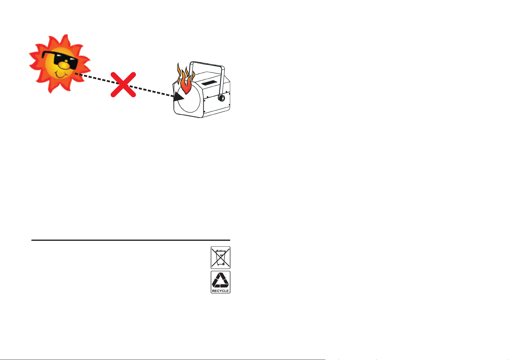
DANGER ~ GEVAAR ~ GEFAHR ~ PELIGRO ~ PERIGO
!
WARNING: DANGER! never expose the lens to direct sunlight, even for a short period. This may damage
the light effect or even cause fire!
ATTENTION: DANGER! n'exposez jamais la lentille directement aux rayons de soleil, même pendant un
bref instant. Ceci peut endommager l'intérieur de l'appareil ou même causer un incendie !
OPGELET : GEVAAR ! stel de lens nooit bloot aan direct zonlicht, zelfs gedurende een korte periode. Dit
kan het toestel beschadigen en zelfs brand veroorzaken!
WARNUNG: GEFAHR! Setzen sie die Linse niemals direkter Sonneneinstrahlung aus, auch nicht für eine
kurze Zeit ! Die direkte Sonneneinstrahlung kann das Gerät zerstören oder zum brennen bringen!
ADVERTENCIA: ¡PELIGRO! ¡nunca exponga la lente a la luz solar directa, aún durante un período corto!
¡Esto puede dañar el efecto de luz o incluso causar el fuego!
AVISO: PERIGO! Nunca exponha as lentes directamente à luz solar, mesmo que por pouco tempo! Isto
pode danificar o efeito luminoso ou mesmo provocar um incêndio!
EN - DISPOSAL OF THE DEVICE
Dispose of the unit and used batteries in an environment friendly manner according to your country regulations.
FR - DÉCLASSER L’APPAREIL
Débarrassez-vous de l’appareil et des piles usagées de manière écologique, conformément aux dispositions
légales de votre pays.
NL - VERWIJDEREN VAN HET APPARAAT
Verwijder het toestel en de gebruikte batterijen op een milieuvriendelijke manier conform de in uw land geldende
voorschriften.
DU - ENTSORGUNG DES GERÄTS
Entsorgen Sie das Gerät und die Batterien auf umweltfreundliche Art und Weise gemäß den Vorschriften Ihres Landes.
ES - DESHACERSE DEL APARATO
Reciclar el aparato y pilas usadas de forma ecologica conforme a las disposiciones legales de su pais.
PT - COMO DESFAZER-SE DA UNIDADE
Tente reciclar a unidade e as pilhas usadas respeitando o ambiente e em conformidade com as normas vigentes no seu país.
Page 3
ENGLISH USER MANUAL
OPERATION MANUAL
Thank you for buying this JB SYSTEMS®product. To take full advantage of all possibilities and for your own
safety, please read these operating instructions very carefully before you start using this unit.
FEATURES
This unit is radio-interference suppressed. This product meets the requirements of the current European and
national guidelines. Conformity has been established and the relevant statements and documents have been
deposited by the manufacturer.
Compact but very powerful moving head for Pro DJ, renting companies and discotheques
Based on the very latest 60WATT LED technology from CREE:
Big light output and sharp gobos, thanks to excellent optics
Very low power consumption, only 95W (money saving!)
Extremely brilliant colors compared to units with halogen lamps
No lamp replacements!
Virtually no heat production
Lightweight (no lamp transformers needed)
0-100% dimming and ultra fast strobe function
6 rotating gobos + open, equipped with gobo shaking feature
Independent color wheel (8 colors + white)
Excellent built-in programs for wonderful, ever changing, light shows:
DMX-control: 11 channels
Standalone: sound activated with internal mic
Master/slave: wonderful s ynchronized shows in standalone mode
DMX-master/slave: thanks to this revolutionary new feature several SIRIUS units, working in
master/slave, can still be controlled by 1 or 4 DMX-channels! (even while connected in a DMX chain,
optional mini DMX splitter required)
Automatic X/Y re-positioning
Optional remote controllers available: wired CA8 or wireless RF8-SET
Easy software updates via special software upgrade unit
LED-display for easy menu navigation
Beam angle = 15°
BEFORE USE
Before you start using this unit, please check if there’s no transportation damage. Should there be any, do
not use the device and consult your dealer first.
Important: This device left our factory in perfect condition and well packaged. It is absolutely necessary
for the user to strictly follow the safety instructions and warnings in this user manual. Any damage caused
by mishandling is not subject to warranty. The dealer will not accept responsibility for any resulting defects
or problems caused by disr egarding this user manual.
Keep this booklet in a safe place for future consultation. If you sell the fixture, be sure to add this user
manual.
Check the contents:
Check that the carton contains the following items:
SIRIUS unit
Omega clamp
IEC-power cable
Eyebolt to install an optional safety cable
Operating instructions
ENGLISH USER MANUAL
SAFETY INSTRUCTIONS:
CAU TI ON
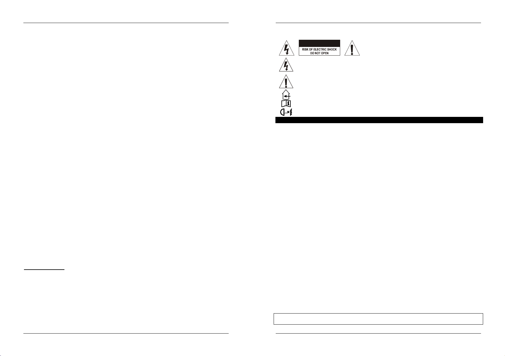
The lightning flash with arrowhead symbol within the equilateral triangle is intended to alert the
use or the presence of un-insulated “dangerous voltage” within the product’s enclosure that may
be of sufficient magnitude to constitute a risk of electric shock.
The exclamation point within the equilateral triangle is intended to alert the user to the presence
of important operation and maintenance (servicing) instructions in the literature accompanying
this appliance.
This symbol means: indoor use only
This symbol means: Read instructions
This symbol determines: the minimum distance from lighted objects. The minimum distance
between light-output and the illuminated surface must be more than 1 meters
CAUTION: Possibly hazardous optical radiation emitted from this product
To protect the environment, please try to recycle the packing material as much as possible.
A new light effect sometimes causes some unwanted smoke and/or smell. This is normal and disappears
after some minutes.
To prevent fire or shock hazard, do not expose this appliance to rain or moisture.
To avoid condensation to be formed inside, allow the unit to adapt to the surrounding temperatures when
bringing it into a warm room after transport. Condense sometimes prevents the unit from working at full
performance or may even cause damages.
This unit is for indoor use only.
Don’t place metal objects or spill liquid inside the unit. Electric shock or malfunction may result. If a foreign
object enters the unit, immediately disconnect the mains power.
Locate the fixture in a well ventilated spot, away from any flammable materials and/or liquids. The fixture
must be fixed at least 50cm from surrounding walls.
Don’t cover any ventilation openings as this may result in overheating.
Prevent use in dusty environments and clean the unit regularly.
Keep the unit away from children.
Inexperienced persons should not operate this device.
Maximum save ambient temperature is 40°C. Don’t use this unit at higher ambient temperatures.
Make sure the area below the installation place is free from unwanted persons during rigging, de-rigging
and servicing.
Always unplug the unit when it is not used for a longer time or when you start servicing.
The electrical installation should be carried out by qualified personal only, according to the regulations for
electrical and mechanical safety in your country.
Check that the available voltage is not higher than the one stated on the rear panel of the unit.
The power cord should always be in perfect condition. Switch the unit immediately off when the power cord
is squashed or damaged. It must be replaced by the manufacturer, its service agent or similarly qualified
persons in order to avoid a hazard.
Never let the power-cord come into contact with other cables!
This fixture must be earthed to in order comply with safety regulations.
Don’t connect the unit to any dimmer pack.
Always use an appropriate and certified safety cable when installing the unit.
In order to prevent electric shock, do not open the cover. there are no user ser viceable parts inside.
Never repair a fuse or bypass the fuse holder. Always replace a damaged fuse with a fuse of the same
type and electrical specifications!
In the event of serious operating problems, stop using the fixture and contact your dealer immediately.
The housing and the lenses must be replaced if they are visibly damaged.
Please use the original packing when the device is to be transported.
Due to safety reasons it is prohibited to make unauthorized modifications to the unit.
Important: Never look directly into the light source! Don’t use the effect in the presence of persons suffering
from epilepsy.
CAUTION: To reduce the risk of electric shock, do not
remove the top cover. No user-serviceable parts inside.
Refer servicing to qualified service personnel only.
JB SYSTEM
®
1/10 SIRIUS
JB SYSTEM
®
2/10 SIRIUS
Page 4

ENGLISH USER MANUAL
ENGLISH USER MANUAL
OVERHEAD RIGGING
Important: The installation must be carried out by qualified service personal only. Improper
installation can result in serious injuries and/or damage to property. Overhead rigging requires
extensive experience! Working load limits should be respected, certified installation materials
should be used, the installed device should be inspected regularly for safety.
Make sure the area below the installation place is free from
unwanted persons during rigging, de-rigging and servicing.
Locate the fixture in a well ventilated spot, far away from
any flammable materials and/or liquids. The fixture must
be fixed at least 50cm from surrounding walls.
The device should be installed out of reach of people and
outside areas where persons may walk by or be seated.
Before rigging make sure that the installation area can hold
a minimum point load of 10times the device’s weight.
Always use a certified safety cable (number 3 on the
picture) that can hold 12 times the weight of the device
when installing the unit. This secondary safety attachment
should be installed in a way that no part of the installation
can drop more than 20cm if the main attachment fails.
The device should be well fixed; a free-swinging mounting
is dangerous and may not be considered!
Don’t cover any ventilation openings as this may result in overheating.
The operator has to make sure that the safety-relating and machine-technical
installations are approved by an expert before using them for the first time. The
installations should be inspected every year by a skilled person to be sure that
safety is still optimal.
1. Optional Clamp
2. Special omega clamp (included)
3. Threaded hole, used to install the supplied eyebolt
4. Optional safety cable
HOW TO SET UP THE UNIT
CONTROL PANEL:
1. DISPLAY shows the various menus and the selected functions.
2. LEDS
DMX On DMX input present
MASTER On Master mode
SLAVE On Slave mode
SOUND Flashing Sound activation
3. BUTTONS
MENU To select the programming functions
DOWN To go backward in the selected functions
UP To go forward in the selected functions
ENTER To confirm the selected functions
4. DMX INPUT/OUTPUT: used for DMX512 linking. Use good quality 3pin XLR M/F balanced cable to link
the units together.
5. WIRED REMOTE CONTROL INPUT: Used to connect a simple CA-8 hand controller while the unit is
used in standalone or master/slave mode.
6. WIRELESS REMOTE CONTROL INPUT: Used to connect RF-8 wireless controller while the unit is used
in standalone or master/slave mode.
7. MAINS INPUT: with IEC socket and integrated fuse holder, connect the supplied mains cable here.
MAIN MENU:
To select any of the functions, press the MENU button up to when the
required one is shown on the display or use the DOWN and UP
buttons to browse the menu.
Select the function with the ENTER button (the display blinks).
Use DOWN and UP buttons to change the mode.
Once the required mode is selected, press the ENTER button to
confirm.
To go back to the main menu without any change press the MENU
button shortly. The main menu is shown in the chart.
DMX Address
Used to set the starting address in a DMX setup.
Press the MENU button until “Addr” is shown on the display.
Press the ENTER button, the display starts blinking.
Use DOWN and UP buttons to change the DMX512 address.
Once the correct address shows on the display, press the ENTER
button to save it.
To go back to the main menu without an y change press the MENU
button shortly.
If you want to go back to normal running mode: press the MENU button
for about 2 seconds.
Channel mode
Used to set the desired channel setup mode.
Press the MENU button until “ChMd” is shown on the display.
Press the ENTER button, the display starts blinking.
Use DOWN and UP buttons to choose 1MSL, 4MSL or 11Chan mode.
Once the desired channel setup mode shows on the display, press
the ENTER button to save it.
To go back to the main menu without an y change press the MENU
button shortly.
If you want to go back to normal running mode: press the MENU button
for about 2 seconds.
Show Mode
Used to choose the Show mode when used in standalone or
master/slave mode.
Press the MENU button until “ShMd” is showing on the display.
Press the ENTER button, the display starts blinking.
Use DOWN and UP buttons to select one of the available shows:
Show 1 (Sh 1): Fixture is placed on the floor. Tilt movement
angle 210°.
Show 2 (Sh 2): Fixture is fixed under ceiling. Tilt movement
angle 90°.
JB SYSTEM
®
3/10 SIRIUS
JB SYSTEM
®
4/10 SIRIUS
Page 5

ENGLISH USER MANUAL
ENGLISH USER MANUAL
Show 3 (Sh 3): Fixture is placed on a podium, in front of the audience. The spot is always
projecting to the audience’s direction; i.e. in front of the stage. Pan movement angle (left to right to
left): 160°. Tilt movement angle: 90° (60° above horizon; 30° below horizon.)
Show 4 (Sh 4): Fixture is fixed under ceiling. The spot is mainly projecting in front of the stage. Pan
movement angle (left to right to left):160°. Tilt movement angle: 90° (verticall y, front 75°; back 15°)
Once the right mode shows on the display, press the ENTER button to save it.
To go back to the main menu without any change press the MENU button shortly.
If you want to go back to normal running mode: press the MENU button for about 2 seconds.
Slave Mode
Used to make the slave unit work in opposite to the master or to work in complete sync.
Press the MENU button until “SLMd” is shown on the display.
Press the ENTER button, the display starts blinking.
Use DOWN and UP button to select “SL 1” (normal) or “SL 2” (2 light show) mode.
Once the mode is selected, press the ENTER button to save it.
To go back to the main menu without any change press the MENU button shortly.
If you want to go back to normal running mode: press the MENU button for about 2 seconds.
Blackout Mode
Blackout mode: when no DMX-signal is detected the unit goes in blackout waiting for a DMX-signal.
No blackout mode: when no DMX-signal is detected, the unit automatically switches to standalone.
Press the MENU button until “bLMd” is shown on the display.
Press the ENTER button, the display starts blinking.
Use DOWN and UP button to select “Yes” (blackout on) or “No” (blackout off) mode.
Once the mode is selected, press the ENTER button to save it.
To go back to the main menu without any change press the MENU button shortly.
If you want to go back to normal running mode: press the MENU button for about 2 seconds.
Sound State
The unit works to rh ythm of the beat when used in standalone or master/slave mode
Press the MENU button until “SOUn” is shown on the display.
Press the ENTER button, the display starts blinking.
Use DOWN and UP button to select “On” or “Off” mode.
Once the mode is selected, press the ENTER button save it.
To go back to the main menu without any change press the MENU button shortly.
If you want to go back to normal running mode: press the MENU button for about 2 seconds.
Sound Sense
Used to set the sensitivity of the internal microphone
Press the MENU button until “SOSe” is shown on the display.
Press the ENTER button, the display starts blinking.
Use DOWN and UP button to select a value between “0” (very low sensitivity) and “100” (high sensitivity).
Once the mode is selected, press the ENTER button save it.
To go back to the main menu without any change press the MENU button shortly.
If you want to go back to normal running mode: press the MENU button for about 2 seconds.
Pan Inversion
Normal: Panning movement is not inversed.
Pan inversion: Panning movement is inversed
Press the MENU button until “IPAn” is shown on the display.
Press the ENTER button, the display starts blinking.
Use DOWN and UP button to select “No” (normal) or “I” (pan inversion) mode.
Once the mode is selected, press the ENTER button to save it.
To go back to the main menu without any change press the MENU button shortly.
If you want to go back to normal running mode: press the MENU button for about 2 seconds.
Tilt Inversion
Normal: Tilt movement is not inversed.
Tilt inversion: tilt movement is inversed
Press the MENU button until “ItLt” is shown on the display.
Press the ENTER button, the display starts blinking.
Use DOWN and UP button to select “No” (normal) or “I” (tilt inversion) mode.
Once the mode is selected, press the ENTER button to save it.
To go back to the main menu without any change press the MENU button shortly.
If you want to go back to normal running mode: press the MENU button for about 2 seconds.
Display on/off
Display on: display is always lit.
Display off: display is dark when not used.
Press the MENU button until the display shows “Led”.
Press the ENTER button, the display starts blinking.
Use DOWN and UP buttons to select “On” (display always lit) or “Off” (display dark when not used).
Once the mode is selected, press the ENTER button to save it.
To go back to the main menu without any change press the MENU button shortly.
If you want to go back to normal running mode: press the MENU button for about 2 seconds.
Display Inversion
Display normal: display is readable when the unit is on the floor.
Display inversion: display is readable when the unit is mounted upside down.
Press the MENU button until “dISP” is shown on the display. (normal display)
Press the ENTER button to toggle between (normal display) and (display inversion).
If you want to go back to normal running mode: press the MENU button for about 2 seconds.
Auto Test
Used to activate the internal “self-test” program which checks all possibilities of the unit.
Press the MENU button until the display shows “teSt”.
Press the ENTER button to start the internal self-test program.
To go back to the functions press the MENU button.
If you want to go back to normal running mode: press the MENU button for about 2 seconds.
Temperature inside the unit
Used to show the temperature inside the unit
Press the MENU button until the display shows “teMP”.
Press the ENTER button to show the internal temperature of the unit on the display.
To go back to the functions press the MENU button again.
If you want to go back to normal running mode: press the MENU button for about 2 seconds.
Fixture Hours
Used to show the number of working hours of the unit.
Press the MENU button until the display shows “FhrS”.
Press the ENTER button to show the number of working hours in the display.
To go back to the functions press the MENU button.
If you want to go back to normal running mode: press the MENU button for about 2 seconds.
Software version
Used to show the software version that is installed in the unit
Press the MENU button until the display shows “ver”.
Press the ENTER button to show the software version on the display.
To go back to the functions press the MENU button.
If you want to go back to normal running mode: press the MENU button for about 2 seconds.
Reset
Used to force a reset of the unit.
Press the MENU button until the display shows “rSet”.
Press the ENTER button to reset the unit.
JB SYSTEM
®
5/10 SIRIUS
JB SYSTEM
®
6/10 SIRIUS
Page 6

ENGLISH USER MANUAL
ENGLISH USER MANUAL
Please also check the chapter about the DMX-channel configuration of the unit to find out how you can force
a reset by DMX.
Home Position Adjust
Used to adjust the home position of several functions:
Make sure that the unit is connected to a DMX-controller and set to 11CH channel mode: set ch6 + ch7 to
maximum.
If you’re not already in the setup menu, just press the MENU button
shortly to enter the setup menu (“Addr” is shown on the display)
Now press the ENTER button for at least 5 seconds to go into
offset mode.
Use DOW N and UP buttons to select the function that you want
to adjust:
oPAn: used to set an offset value for the pan function.
otIL: used to set an offset value for the tilt function.
oCoL: used to adjust the positioning of the color wheel.
oGob: used to adjust the positioning of the gobo wheel.
Press the ENTER button, the display starts blinking.
Use DOWN and UP buttons to adjust the home position
Press the ENTER button to confirm your setting
To go back to the functions without any change press the MENU
button again.
If you want to go back to normal running mode: press the MENU button for about 2 seconds, the new offset
parameters for the different functions are preserved in flash memory.
ELECTRICAL INSTALLATION + ADDRESSING
Important: The electrical installation should be carried out by qualified personal only,
according to the regulations for electrical and mechanical safety in your country.
Electrical installation for 1 standalone unit:
Just insert the mains cable. The unit starts working immediately in stand-alone mode.
Remark1: You can connect a CA-8 or RF-8 remote controller to the unit if you want to have more control.
Refer to “how to operate the unit” to learn how to do this.
Remark2: if there’s no output, please make sure to set the unit in master mode and set the blackout mode
to “NO” and Sound State to “On” (see previous chapter)
Electrical installation for two or more units in master/slave:
In this mode the units will show a synchronized show, working to the rhythm of the beat.
Electrical installation for two or more units in DMX-master/slave:
In this mode the units will show a synchronized show, working to the rhythm of the beat but you can still
control some functions on the master by 1 or 4 DMX-channels.
To assure proper operation you need an optional “Mini DMX-SPLITTER” (order code: 4630) to isolate
the master/slave line from the main DMX-line, see drawing.
Connect 2 to maximum 16 units together using good quality balanced microphone cables. The first unit
in the chain will act as the master, the other units will act automatically as slaves.
Set the master to 1MSL or 4MSL channel mode (see previous chapter). Check the DMX-chart below to
see the difference between both channel modes.
For the DMX-controller the master and his slaves can now be considered as 1 virtual effect that needs a
start address so it can be controlled as any other DMX-unit in the DMX chain: see “DMX Address” in the
chapter “Main Menu” to see how you can set the DMX-start address.
Make sure that all units are connected to the mains.
Set the DMX-controller according to the DMX-chart below.
Done!
Remark: in order to work well to the rhythm of the music, make sure that the option “Sound State” on the
master is set to “On” (see previous chapter)
DMX-Chart for 1MSL and 4MSL working modes
1 MSL 4 MSL
Connect 2 to maximum 16 units together using good quality balanced microphone cables. The first unit
in the chain will automatically act as the master, the other units will act automatically as slaves.
Make sure that all units are connected to the mains.
Done!
Remark: You can connect a CA-8 or RF-8 remote controller to the master unit if you want to have more
control over the master/slave operation
Remark2: if there’s no output, please make sure to set the first unit in master mode and set the blackout
mode to “NO” and Sound State to “On” (see previous chapter)
JB SYSTEM
®
7/10 SIRIUS
Electrical installation in DMX-mode:
The DMX-protocol is a widely used high speed signal to control intelligent light equipment. You need to
“daisy chain” your DMX controller and all the connected units with a good quality balanced cable.
Both XLR-3pin and XLR-5pin connectors are used, however XLR-3pin is more popular because these
cables are compatible with balanced audio cables.
Pin layout XLR-3pin:
JB SYSTEM
Pin1 = GND ~ Pin2 = Negative signal (-) ~ Pin3 = Positive signal (+)
®
8/10 SIRIUS
Page 7

ENGLISH USER MANUAL
ENGLISH USER MANUAL
Pin layout XLR-5pin:
To prevent strange behavior of the light effects, due to interferences, you must use a 90Ω to 120Ω
terminator at the end of the chain. Never use Y-splitter cables, this simply won’t work!
Make sure that all units are connected to the mains.
Each light effect in the chain needs to have its proper starting address so it knows
which commands from the controller it has to decode. In the next section you will
learn how to set the DMX addresses.
HOW TO SET THE RIGHT STARTING ADDRESS:
Refer to the previous chapter (DMX-512 address setting) to learn how to set the starting address on this unit.
The starting address of each unit is very important. Unfortunately it is impossible to tell you in this user
manual which starting addresses you have to set because this completely depends on the controller you will
use… So please refer to the user manual of your DMX-controller to find out which starting addresses you
must set.
DMX-CONFIGURATION OF SIRIUS:
Pin1 = GND ~ Pin2 = Negative signal (-) ~ Pin3 = Positive signal (+) ~ Pins4+5 not used.
OPERATE THE UNIT BY CA8 OR RF8SET
When used in standalone or master/slave mode we strongly advise you to use the CA-8 “Wired easy
controller” or RF-8SET “Wireless easy controller”.
CA-8 wired remote: Connect the controller to the jack input of the first unit (master).
RF-8SET wireless remote: the wireless remote has two parts:
RF-8T: small RF-transmitter that can control up to 5 effects.
RF-8R: small RF-receiver that should be connected to the DIN 5pin input of
Now you can control all the connected units:
STANDBY BUTTON:
Press this button to start/stop blackout mode on all connected units.
MODE/FUNCTION BUTTONS:
With the MODE button you can select 3 different modes:
The LED is off: with the FUNCTION button you can select different
The LED is blinking: with the FUNCTION button you can select
The LED is on: (music mode is temporarily switched off)
the SIRIUS. See the installation manual of the receiver for more information.
strobe modes, like “sound strobe”.
different shows.
Press the FUNCTION button shortly: to change the colors
Press the FUNCTION button longer: to change the gobos
MAINTENANCE
Make sure the area below the installation place is free from unwanted persons during servicing.
Switch off the unit, unplug the mains cable and wait until the unit is cooled down.
During inspection the following points should be checked:
All screws used for installing the device and any of its parts should be tightly fastened and may not be
corroded.
Housings, fixations and installations spots (ceiling, truss, suspensions) should be totally free from any
deformation.
When an optical lens is visibly damaged due to cracks or deep scratches, it must be replaced.
The mains cables must be in impeccable condition and should be replaced immediately when even a
small problem is detected.
In order to protect the device from overheat the cooling fans (if any) and ventilation openings should be
cleaned monthly.
The interior of the device should be cleaned annually using a vacuum cleaner or air-jet.
The cleaning of internal and external optical lenses and/or mirrors must be carried out periodically to
optimize light output. Cleaning frequency depends on the environment in which the fixture operates: damp,
smoky or particularly dirty surroundings can cause greater accumulation of dirt on the unit’s optics.
Clean with a soft cloth using normal glass cleaning products.
Always dry the parts carefully.
Clean the external optics at least once every 30 days.
Clean the internal optics at least every 90 days.
Attention: We strongly recommend internal cleaning to be carried out by qualified personnel!
JB SYSTEM
SPECIFICATIONS
Mains Input: AC 100 - 240V, 50/60Hz
Max Power consumption: 95 Watt
Sound Control: Internal microphone
Pan/Tilt: 540° / 270°
Beam angle: 15°
DMX connections: 3pin XLR male / female
Leds: 1 White LED 60Watt
Size: See drawing
Weight: 8,80 kg
You can download the latest version of this user manual on our website: www. beglec.com
®
9/10 SIRIUS
JB SYSTEM
Every information is subject to change without prior notice
®
10/10 SIRIUS
 Loading...