

Page 1
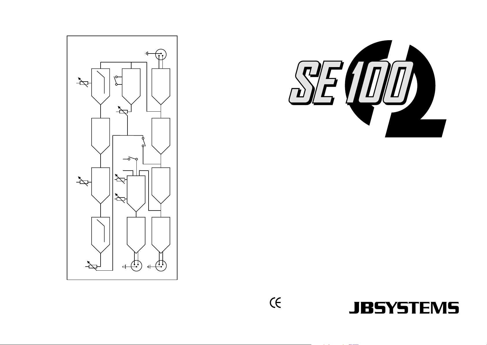
BLOCK DIAGRAM OF THE SE100
CONNECTOR
FEMALE
XLR
1 GND
AUDIO INPUT 1
2+
3-
PROCESSOR
HP HP
TUNE
CHANNEL 2 DUPLICATES CHANNEL
NOTE:
SHIFT
PHASE
DELAY
BASS
LOW MIX
PHASE
BALANCED
INPUT
AMPLIFIER
BUFFER
BYPASS
MULTIBAND SOUND PROCESSOR
CH2
PROCESSOR
SOUND
PROCESSOR
HIGH MIX
TO
VARIABLE
SUB X-OVER
X-OVER
LEVEL
BALANCED
OUTPUT
GND 1
2+
3-
REDUCTION
NOISE
Operation Manual
BALANCED
OUTPUT
Mode d'emploi
Gebruiksaanwijzing
Bedienungsanleitung
SUB OUTPUT
CH1 OUTPUT
GND 1
2+
3-
Manual de instrucciones
Manual do utilizador
EN
FR
NL
DU
ES
PT
WWW.BEGLEC.COM
Copyright © 2005 by BEGLEC cva.
Reproduction or publication of the content in any manner, without express permission of the publisher, is prohibited.
Version: 1.1
The Power Source for DJ’s
Page 2

DISPOSAL OF THE DEVICE
Dispose of the unit and used batteries in an environment friendly manner
according to your country regulations.
DÉCLASSER L’APPAREIL
Débarrassez-vous de l’appareil et des piles usagées de manière écologique
Conformément aux dispositions légales de votre pays.
VERWIJDEREN VAN HET APPARAAT
Verwijder het toestel en de gebruikte batterijen op een milieuvriendelijke
manier conform de in uw land geldende voorschriften.
ENTSORGUNG DES GERÄTS
Entsorgen Sie das Gerät und die Batterien auf umweltfreundliche Art und
Weise gemäß den Vorschriften Ihres Landes.
DESHACERSE DEL APARATO
Reciclar el aparato y pilas usadas de forma ecologica conforme a las
disposiciones legales de su pais.
Page 3
ENGLISH OPERATION MANUAL
ENGLISH OPERATION MANUAL
SAFETY INSTRUCTIONS:
OPERATION MANUAL
FEATURES
• Professional multi-band sound enhancer: adds harmonics to the sound which
increases definition, presence and transparency.
• Improves bass punch considerably
• Separate variable subwoofer output with adjustable cutoff frequency
• Subwoofer inverter switch
• 50Hz/100Hz low cut filter
• Variable sound processing for perfect sound balance
• Enhancer multi-band tuning from 1kHz to 8kHz.
• Balanced XLR inputs/outputs
BEFORE USE
Check the contents:
Check that the carton contains the following items:
• SE 100 Enhancer unit
• Operating instructions
• Power cord with IEC-plug
To prevent fire or shock hazard, do not expose this appliance to rain or moisture. Do
not place metal objects or spill liquid inside the unit. Electric shock or malfunction
may result.
INSTALLATION GUIDELINES:
• Install the unit in a well-ventilated location where it will not be exposed to high
temperatures or humidity.
• Placing and using the unit for long periods near heat-generating sources such as
amplifiers, spotlights, etc. will affect its performance and may even damage the
unit.
• The unit can be mounted in 19-inch racks. Attach the unit using the 4 screw holes
on the front panel. Be sure to use screws of the appropriate size. (screws not
provided)
Take care to minimize shocks and vibrations during transport.
• When installed in a booth or flight case, please make sure to have good ventilation
to improve heat evacuation of the unit.
• To avoid condensation to be formed inside, allow the unit to adapt to the
surrounding temperatures when bringing it into a warm room after transport.
Condense sometimes prevents the unit from working at full performance.
CAUTION
The lightning flash with arrowhead symbol within the equilateral triangle
is intended to alert the use or the presence of un-insulated “dangerous
voltage” within the product’s enclosure that may be of sufficient
magnitude to constitute a risk of electric shock.
The exclamation point within the equilateral triangle is intended to alert
the user to the presence of important operation and maintenance
(servicing) instructions in the literature accompanying this appliance.
CAUTION: To reduce the risk of electric
shock, do not remove any cover. No userserviceable parts inside. Refer servicing to
qualified service personnel only.
JB SYSTEMS® 1/29 SE 100
CONNECTIONS
This sound enhancer can be used in different ways. Basically the unit is connected
between the music source (any line output is possible) and the unit that will be used
to record or amplify the music:
• In most cases SE100 will be used to enhance the sound quality and bass punch in
PA systems and discotheque sound systems. The SE100 will be connected behind
the master output of the audio mixer. You can also use the subwoofer output to
drive an extra subwoofer amplifier which results in an additional power punch!
• SE100 can be inserted in the monitor send of a PA mixer to enhance the sound
quality of monitor speakers.
• SE100 can also be used between a tape deck and mixing console to enhance the
sound of the tape deck.
• SE100 can be connected between the record output of a mixing console and a tape
deck to enhance the sound that will be recorded.
• SE100 can be used to correct the loss of sound quality, caused by all kinds of effect
equipment. In this case put the SE100 as last unit in the chain of effect equipment.
JB SYSTEMS® 2/29 SE 100
Page 4

ENGLISH OPERATION MANUAL
• SE100 can be used to compensate the loss of sound definition during tape
duplication: the copy can be even better than the original! Put the SE100 between
the output of the playback deck and the input of the recording deck.
For additional information on connections please refer to the next paragraph.
ENGLISH OPERATION MANUAL
FRONT PANEL: CONTROLS AND USE
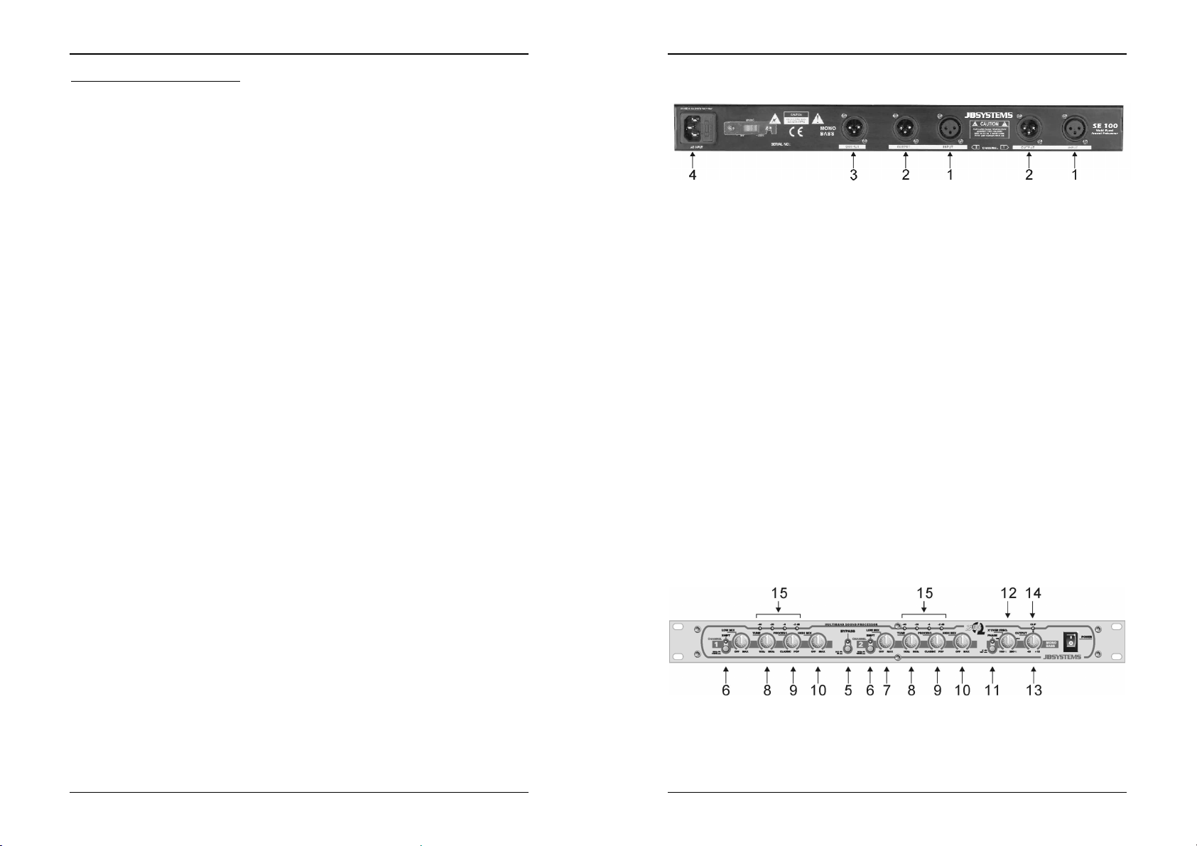
REAR PANEL:
1. INPUT connector: this female XLR-connector accepts both unbalanced and
balanced line signals from the unit that needs audio enhancement.
• For balanced use, please follow these conventions:
Pin1 = Ground ~ Pin2 = Hot (+) ~ Pin3 = Cold (-)
Readymade cables are available from JB Systems (ex. 7-0063 ~ 5m XLR m/f)
• For unbalanced use, connect Pin3 (-) to Pin1 (ground/shield)
Readymade cables are available from JB Systems (2-0445 ~ cinch/XLR m)
2. OUTPUT connector: this male XLR-connector can be connected to both
unbalanced and balanced line inputs.
• For balanced use, please follow these conventions:
Pin1 = Ground ~ Pin2 = Hot (+) ~ Pin3 = Cold (-)
Readymade cables are available from JB Systems (ex. 7-0063 ~ 5m XLR m/f)
• For unbalanced use, connect Pin3 (-) to Pin1 (ground/shield)
Readymade cables are available from JB Systems (2-0440 ~ cinch/XLR f)
3. SUBWOOFER OUTPUT connector: this male XLR-connector can be connected
to both unbalanced and balanced inputs of subwoofer amplifiers. The cutoff
frequency and level of this output are adjustable.
• For balanced use, please follow these conventions:
Pin1 = Ground ~ Pin2 = Hot (+) ~ Pin3 = Cold (-)
Readymade cables are available from JB Systems (ex. 7-0063 ~ 5m XLR m/f)
• For unbalanced use, connect Pin3 (-) to Pin1 (ground/shield)
Readymade cables are available from JB Systems (2-0440 ~ cinch/XLR f)
4. Mains input: connect the sound enhancer to the 220V AC mains, using the
supplied power-cord.
CONNECTIONS
5. ACTIV switch: This button switches the processor over between operation and
bypass. When the button is pressed the blue led turns on to indicate that the
processor works. You can use this switch to compare the sound with and without
processing. This makes it easier to tune the sound using trial and error.
6. SHIFT switch: Sets the cutoff lower frequency of the bass processor. Depending
on the situation you can select 50Hz or 100Hz cutoff frequency for the bass
processor. This function also helps reducing system load.
7. LOW MIX control: Controls the amount of low band signal, produced by the bass
processor, used for sound enhancement (from zero to maximum). The setting
depends on the application and can be adapted to your own taste. When
adjusting, use the ACTIV switch to compare between original and processed
sound.
Important: Note that the bass processor should be used with care to avoid
possible speaker damage. Most smaller and economical speakers are not
capable of handling the low frequencies produced by this unit.
8. TUNE control: Sets the cutoff frequency of the high-pass filter. In a range from
1kHz to 8kHz you can select the frequencies that are routed to the high band
processor.
9. PROCESSOR control: controls the efficiency of the high band processor. The
signals’ transparency and sharpness increases while turning the control knob in
clockwise direction. When adjusting, use the ACTIV switch to compare between
original and processed sound.
10. HIGH MIX control: Controls the amount of signal, produced by the high band
processor, used for sound enhancement (from zero to maximum). The setting
depends on the application. It can be used to give a high-quality system the little
“finishing touch” it needs or you can add some extra clarity to a relatively poor
sound system. In any case it is up to you to adapt the sound to your own taste.
Always start adjusting with the HIGH MIX control turned in counterclockwise
position and use the ACTIV switch often to compare between original and
processed sound.
Important: Note that the high band processor should be used with care to avoid
possible tweeter damage. Improper and excessive use of high band processor
can cause overload to the tweeters of your speakers. Always start tuning the high
band processor with the HIGH MIX control completely turned to the left.
11. PHASE INVERT switch: To add more bass punch, a subwoofer can be
connected to the subwoofer output. Sometimes the conductors of the subwoofer
are inversed which results in poor sound quality with a lack of low frequencies:
the opposite of what you expected! This can be corrected by inversing the (+) and
(-) poles of the cabling to your subwoofer or … by pushing the PHASE INVERT
JB SYSTEMS® 3/29 SE 100
JB SYSTEMS® 4/29 SE 100
Page 5
ENGLISH OPERATION MANUAL
switch! Press the phase invert switch and compare the results of both positions.
The position with the most bass production is the right one!
12. X-OVER FREQ. control: (crossover frequency control) adjusts the cutoff
frequency of the subwoofer low pass filter. This crossover frequency can be set in
a range of 100 to 250Hz. Once again it is up to you to adapt its position to your
own taste. For most subwoofers 100Hz to 150Hz seems to be the best choice.
13. OUTPUT control: Controls the level of the subwoofer output from zero to +12dB.
Start from zero and slowly turn in clockwise direction until the amount of low
frequencies seems to be OK for you.
14. CLIP LED: When the subwoofer output level is too big, clipping may occur. In this
case the clip led turns on. No problem if the led blinks from time to time. However
when this happens too often, it’s time to lower the subwoofer output signal.
Note: Clipping means deformation and deformation means possible damage to
your subwoofer…
15. LED BAR: Small led bar indicates the output level of both enhancer outputs.
SPECIFICATIONS
Max. input level / impedance: +20dBu unbalanced / 40kΩ
Max. output level / impedance: +20dBu unbalanced / 40Ω
Common mode rejection (CMRR): >40dB
Frequency response: 10-30.000Hz (+/-0.5dB)
THD(A) + noise: 0.005% +4dB
IMD Intermodulation distortion: 0.01% +10dB
S/N Ratio (IHF-A): >94dB (20-20.000Hz)
Crosstalk @20kHz: > -83dBu
Power Supply: AC 230 V, 50Hz
Power Consumption: 10W
Fuse: 0.5A slow blow
Dimensions: 482(W) x 44(H) x 154(D) mm
Weight: 1Kgs
SURF TO:
WWW.BEGLEC.COM
AND LOOK FOR OTHER PRODUCTS FROM JB SYSTEMS
FRANCAIS MODE D’EMPLOI
MODE D’EMPLOI
CARACTERISTIQUES
• Sound enhancer multi-bandes professionnel: ajoute des harmoniques au son, ce
qui augmente la définition, la présence et la transparence.
• Accentue considérablement les basses (plus de punch)
• Sortie séparée pour le sub-woofer avec réglage du niveau de sortie et de la
fréquence de coupure.
• Inverseur de polarité du sub-woofer
• Filtre « low cut » 50Hz/100Hz
• Traitement variable du son pour une balance sonore parfaite
• Enhancer multi-bandes : tuning de 1kHz à 8kHz.
• Entrées / sorties XLR balancées
AVANT L’UTILISATION
Vérifiez le contenu:
Vérifiez si la boite contient les articles suivants :
• Le SE 100
• Le mode d’emploi
• Câble d’alimentation au connecteur IEC
CONSEILS DE SECURITE:
à un service technique compétent.
ce appareil à la pluie ou à l'humidité.
Ne pas insérer d'objets métalliques et ne pas verser de liquides dans l'appareil. Il
pourrait en résulter des électrocutions ou des dysfonctionnements.
CAUTION
Ce symbole attire l'attention de l'utilisateur sur la présence de 'voltage
dangereux' à l'intérieur du couvercle. Se voltage est suffisamment élevé
pour constituer un risque d'électrocution.
Ce symbole vous averti de la présence d'instructions importantes concernant
l'utilisation et l'entretient accompagnant cet appareil.
Afin de prévenir tout risque d'incendies et d'électrocutions, ne pas exposer
ATTENTION: Afin d'éviter tout risque
d'électrocution, ne pas soulever le châssis de
l'appareil. L'intérieur ne contient aucune pièce
remplaçable par l'utilisateur. Confier l'appareil
JB SYSTEMS® 5/29 SE 100
JB SYSTEMS® 6/29 SE 100
Page 6
FRANCAIS MODE D’EMPLOI
CONSEILS D'INSTALLATION:
• Installer l'appareil dans un lieu bien aéré, à l'abri de l'humidité et des fortes
températures.
• Placer et utiliser l'appareil à proximité de sources de chaleur telles que spots,
amplis,… pourrait affecter ses performances et même endommager l'appareil.
• L'appareil peut être installé dans un rack 19''. Fixer l'appareil en utilisant les 4 trous
pour vis sur la face avant. Assurez-vous d'utiliser des vis de la bonne dimension
(vis non fournies). Essayez d'éviter les vibrations et les coups lors du transport.
• En cas d'installation dans un 'flight case', assurer une bonne ventilation afin
d'évacuer la chaleur produite par l'appareil.
• Pour éviter la condensation à l'intérieur, laisser l'appareil s'adapter à la nouvelle
température ambiante après le transport. La condensation peut altérer les
performances de l'appareil.
CONNECTIONS
Ce Sound Enhancer peut être utilisé de différentes façons. L’appareil sera connecté
entre la source sonore (n’importe quelle sortie ligne est possible) et l’appareil qui
sera utilisé pour enregistrer ou amplifier la musique:
• Dans la plupart des cas le SE100 sera utilisé pour améliorer la qualité sonore et
pour ajouter de punch aux basses fréquences dans des systèmes PA et les
systèmes sonores dans les discothèques. Le SE100 sera connecté à la sortie
Master de la table de mixage. Vous pouvez aussi utiliser la sortie sub-woofer pour
commander un amplificateur de sub-woofer supplémentaire, ce qui donnera un
résultat encore plus impressionnant !
• Le SE100 peut être inséré dans les sorties Monitor d’une console de mixage pour
PA pour augmenter la qualité sonore des retours.
• Le SE100 peut aussi être connecté entre la sortie d’un lecteur de cassettes et une
table de mixage pour augmenter la qualité sonore à l’écoute des cassettes.
• Le SE100 peut être connecté entre la sortie d’enregistrement d’une table de
mixage et l’entrée d’un enregistreur afin d’augmenter la qualité de l’enregistrement.
• Le SE100 peut être utilisé afin de corriger la perte de qualité sonore, causé par
toutes sortes d’effets. Dans ce cas, placez le SE100 comme dernier maillon dans la
chaîne d’effets.
• Le SE100 peut être utilisé pour compenser la perte de définition lors de la
duplication de bandes sonores. La copie peut même s’avérer meilleure que
l’original! Connectez le SE100 entre la sortie du deck de lecture et l’entrée du deck
d’enregistrement.
Pour plus d’informations sur les connections, referez vous au paragraphe suivant.
FRANCAIS MODE D’EMPLOI
PANNEAU ARRIÈRE: CONNECTIONS
1. INPUT: Ce connecteur d’entré XLR accepte des signaux ligne, balancés ou non,
2. OUTPUT: ce connecteur de sortie XLR peut être connecté aux entrées line
3. SUBWOOFER OUTPUT: ce connecteur XLR mâle peut être connecté aux
4. Mains input: connectez le Sound Enhancer au secteur 220V AC en utilisant le
PANNEAU FRONTAL: + UTILISATION
des appareils qui ont besoin d’une amélioration sonore.
• Utilisez la configuration suivante pour une utilisation balancée:
Pinne1 = masse ~ Pinne2 = point chaud (+) ~ Pinne3 =point froid (-)
Des câbles tout-faits JB Systems sont disponibles (ex. 7-0063 ~ 5m XLR m/f)
• Pour une utilisation non-balancée, connectez la pinne3 (-) à la pinne1
Des câbles tout-faits JB Systems sont disponibles (2-0445 ~ cinch/XLR m)
balancées ou non-balancées.
• Utilisez la configuration suivante pour une utilisation balancée:
Pinne1 = masse ~ Pinne2 = point chaud (+) ~ Pinne3 = point froid (-)
Des câbles tout-faits JB Systems sont disponibles (ex. 7-0063 ~ 5m XLR m/f)
• Pour une utilisation non-balancée, connectez la pinne3 (-) à la pinne1
Des câbles tout-faits JB Systems sont disponibles (2-0440 ~ cinch/XLR f)
entrées balancées ou non-balancées des amplificateurs de sub-woofer. La
fréquence de coupure et le niveau de sortie peuvent être ajustés.
• Utilisez la configuration suivante pour une utilisation balancée:
Pinne1 = masse ~ Pinne2 = point chaud (+) ~ Pinne3 = point froid (-)
Des câbles tout-faits JB Systems sont disponibles (ex. 7-0063 ~ 5m XLR m/f)
• Pour une utilisation non-balancée, connectez la pinne3 (-) à la pinne1
Des câbles tout-faits JB Systems sont disponibles (2-0440 ~ cinch/XLR f)
câble d’alimentation fourni avec l’appareil.
JB SYSTEMS® 7/29 SE 100
5. Interrupteur ACTIV: vous permet de rendre le processeur opérationnel ou de le
mettre en bypass. Si la touche est enfoncée, le led bleu est allumé et indique que
le processeur est opérationnel. Vous pouvez utiliser cette touche pour comparer
le son original avec le son corrigé.
JB SYSTEMS® 8/29 SE 100
Page 7

FRANCAIS MODE D’EMPLOI
6. Interrupteur SHIFT: vous permet de sélectionner la fréquence de coupure du
processeur de basses. Selon les besoins, vous pouvez sélectionner 50Hz ou
100Hz. Cette fonction vous aide aussi à réduire la charge du système.
7. LOW MIX: Contrôle le niveau du signal produit par le processeur de basses
fréquences, utilisés pour l’augmentation de la qualité sonore (de zéro au
maximum) Le réglage dépend de l’application et peut être adapté selon votre
propre goût. Utilisez la touche ACTIV pendant le réglage, pour comparer le son
modifié au son original.
Important: Notez que le processeur de basses fréquences doit être utilisé avec
prudence pour éviter d’endommager les haut-parleurs. La plupart des hautparleurs bon- marchés ne sont pas capables de reproduire convenablement les
basses fréquences produits par cet appareil.
8. TUNE: Règle la fréquence de coupure du filtre des hautes fréquences. Vous
pouvez sélectionner les fréquences qui sont envoyés dans le processeur de
hautes fréquences, allant de 1kHz à 8kHz.
9. PROCESSOR: contrôle l’efficacité du processeur de hautes fréquences. La
transparence et la précision du signal augmentent si vous tournez le bouton dans
le sens des aiguilles d’une montre. Utilisez la touche ACTIV pendant le réglage
pour comparer le son modifié au son original
10. HIGH MIX: Contrôle le niveau du signal produit par le processeur de hautes
fréquences pour l’augmentation de la qualité sonore (de zéro au maximum) Le
réglage dépend de l’application. Il peut être utilisé pour ajouter cette petite
« touche finale » aux systèmes de haute qualité ou peut donner un peu plus de
clarté aux systèmes de moindre qualité. De toute façon, c’est à vous d’adapter le
son a votre propre goût. Commencez toujours avec le bouton de contrôle HIGH
MIX tourné en position de départ (contre-sens des aiguilles d’une montre) et
utilisez souvent la touche ACTIV pour comparer le son original au son corrigé par
le processeur.
Important: Notez que le processeur de hautes fréquences doit être utilisé avec
prudence pour éviter que le tweeter soit endommagé. Une utilisation excessive
inadaptée du processeur de hautes fréquences peut causer une surcharge des
tweeters de vos enceintes. Commencez toujours le réglage du processeur de
hautes fréquences avec le bouton de contrôle HIGH MIX complètement tourné
vers la gauche.
11. PHASE INVERT: Pour obtenir un meilleur rendu des basses fréquences on peut
connecter un sub-woofer à la sortie « sub-woofer » du processeur. Il se peut que
les câbles du sub-woofer soient inversés, ce qui résulte en une mauvaise qualité
sonore, dépourvu de basses fréquences ; l’inverse de ce que l’on voulait obtenir !
Ceci peut être corrigé en inversant les pôles (+) et (-) du câblage du sub-woofer
ou... en appuyant simplement sur la touche PHASE INVERT ! (Inversion de
phase) Utilisez cette touche pour comparer le résultat dans chaque position. La
position qui produit le plus de basses est la bonne!
12. X-OVER FREQ: (contrôle de fréquence du cross-over) règle la coupure de
fréquence du filtre low-pass du sub-woofer. Cette fréquence peut être réglée de
100 à 250Hz. Une fois de plus, c’est à vous d’adapter ce réglage selon votre
propre goût. Pour la plupart de sub-woofers 100Hz à 150Hz semble être le
meilleur choix.
13. OUTPUT: Contrôle le niveau de sortie du sub-woofer de zéro à +12dB. Démarrez
de zéro et augmentez lentement le volume en tournant le bouton dans le sens
des aiguilles d’une montre, jusqu’a-ce que le niveau de basses fréquences désiré
soit obtenu.
JB SYSTEMS® 9/29 SE 100
FRANCAIS MODE D’EMPLOI
14. CLIP LED: Quant le niveau de sortie du sub-woofer est trop élevé, une
15. LED BAR: Le led-bar indique le niveau de sortie des deux sorties de l’appareil.
SPECIFICATIONS
Niveau Max d’entrée / impédance: +20dBu non-balancé / 40kΩ
Niveau Max de sortie / impédance: +20dBu non-balancé / 40Ω
Common mode rejection (CMRR): >40dB
Réponse de fréquence: 10-30.000Hz (+/-0.5dB)
THD(A) + bruit: 0.005% +4dB
IMD Intermodulation distortion: 0.01% +10dB
Rapport Signal/Bruit (IHF-A): >94dB (20-20.000Hz)
Séparation des canaux @20kHz: > -83dBu
Alimentation: AC 230 V, 50Hz
Consommation: 10W
Fusible: 0.5A lent
Dimensions: 482(L) x 44(H) x 154(P) mm
Poids: 1Kg
JB SYSTEMS® 10/29 SE 100
déformation du son peut apparaître. Dans ce cas le Clip Led s’allume. Ceci ne
devrait pas poser de problèmes si le led s’allume de temps en temps pendant
une fraction de secondes. Par contre, si cela arrive trop souvent, il est grand
temps de diminuer le niveau de sortie du sub-woofer.
Remarque: Clipping signifie déformation et déformation signifie qu’il y à un risque
de dégât au haut -parleurs…
SURF TO:
WWW.BEGLEC.COM
AND LOOK FOR OTHER PRODUCTS FROM JB SYSTEMS
Page 8

NEDERLANDS GEBRUIKSAANWIJZING
GEBRUIKSAANWIJZING
EIGENSCHAPPEN
• Professionele multi-band sound enhancer: voegt harmonischen tonen toe aan de
muziek wat de definitie en de transparantie verhoogt.
• Dynamiseert behoorlijk de bassen.
• Gescheiden regelbare subwoofer uitgang met instelbare afsnijfrequenties
• Polariteit inversieschakelaar voor de subwoofer
• 50Hz/100Hz low cut filter
• Variabele sound processor voor een perfecte geluidsbalans
• Enhancer multi-band tuning van 1kHz tot 8kHz.
• Gebalanceerde XLR ingangen/uitgangen
VÓÓR GEBRUIK
Controleer de inhoud:
Kijk na of de doos volgende items bevat:
• SE 100 Enhancer
• Gebruiksaanwijzing
• Voedingskabel met IEC stekker
VEILIGHEIDSVOORSCHRIFTEN:
CAUTION
vervangen. Voor reparaties doet U best uitsluitend beroep op degelijk
opgeleid personeel.
De driehoek met bliksem symbool waarschuwt U dat er in dit apparaat
ongeïsoleerde spanning aanwezig is die bij aanraking een elektrische
schok kan veroorzaken.
De driehoek voorzien van een uitroepteken waarschuwt U dat er
belangrijke gebruikersinstructies in de bijbehorende handleiding te vinden
zijn.
Om elektrische schokken te voorkomen mag dit apparaat niet aan regen en vocht
worden blootgesteld. Breng geen metalen voorwerpen in de mengtafel en zorg
ervoor dat er geen vloeistoffen in het apparaat terecht kunnen komen. Elektrische
schokken of slechte werking kunnen het gevolg zijn.
JB SYSTEMS® 11/29 SE 100
OPGELET: Gelieve, om het risico op
elektrische schokken te vermijden, het
apparaat niet zelf te openen. Binnenin
vindt U geen onderdelen die U zelf kan
NEDERLANDS GEBRUIKSAANWIJZING
INSTALLATIEVOORSCHRIFTEN:
• Plaats de mengtafel in een goed geventileerde ruimte waar zij niet blootgesteld is
aan hoge temperaturen of vocht.
• Het plaatsen en het gebruik van de mengtafel gedurende een lange periode in de
nabijheid warmtebronnen zoals versterkers, spots, enz. zal zijn werking
beïnvloeden.
• De mixer kan in een 19” kast gemonteerd worden. Monteer de behuizing door
middel van de 4 montageopeningen op de frontplaat. Gebruik hiervoor bouten van
de juiste dikte! (deze zijn niet inbegrepen) Probeer sterke schokken en vibraties
tijdens het transport zo veel mogelijk te vermijden.
• Zorg, bij inbouw in een vaste installatie of flightcase, voor een goede ventilatie om
de warmte optimaal te kunnen afvoeren.
• Zorg ervoor, om inwendige vorming van condensatie te voorkomen, dat de
mengtafel zich na transport kan aanpassen aan de warme binnentemperatuur.
Condensatie kan de goede werking soms verhinderen.
VERBINDINGEN
Deze sound enhancer kan op verschillende manieren gebruikt worden.
Normalerwijze wordt het toestel verbonden tussen de geluidsbron (elke line uitgang
is mogelijk) en het toestel dat gebruikt wordt om de muziek te versterken of op te
nemen:
• Meestal wordt de SE100 gebruikt om de geluidskwaliteit en de basweergave van
PA of discotheekinstallaties op te krikken. De SE100 wordt verbonden aan de
master uitgang van de mengtafel. Men kan ook de subwoofer uitgang gebruiken om
een extra subwoofer versterker aan te sturen, wat zal leiden tot een nog krachtigere
“Bass punch”!
• De SE100 kan in een monitor uitgang van een PA gevoegd worden om de
geluidskwaliteit van de monitors te verbeteren.
• De SE100 kan ook gebruikt worden tussen een tapedeck en een mengtafel om de
geluidskwaliteit van de tapedeck te verbeteren.
• De SE100 kan aangesloten worden tussen de opname-uitgang van een mengtafel
en een taperecorder om de geluidskwaliteit van de opname te verbeteren.
• De SE100 kan gebruikt worden om het kwaliteitsverlies, veroorzaakt door het
gebruik van verschillende effectapparatuur, op te vangen. Plaats in dit geval de
SE100 als laatste schakel in de effectenketting.
• De SE100 kan gebruikt worden om het kwaliteitsverlies tijdens het dupliceren van
geluidsbanden te compenseren. De kopie kan zelfs beter klinken dan de originele
band! Plaats de SE100 tussen de uitgang van de tapedeck (weergave) en de
ingang van de taperecorder.
Zie volgende paragraaf voor bijkomende informatie over aansluitingen.
JB SYSTEMS® 12/29 SE 100
Page 9

NEDERLANDS GEBRUIKSAANWIJZING
ACHTERZIJDE: aansluitingen
1. INPUT: deze vrouwelijke XLR aansluitingen aanvaarden zowel gebalanceerde als
niet-gebalanceerde line signalen van geluidsbronnen die een geluidsverbetering
nodig hebben.
• Volg volgende voorschriften voor een gebalanceerde aansluiting:
Pin1 = Grond ~ Pin2 = Warm (+) ~ Pin3 = Koud (-)
Afgewerkte JB Systems kabels zijn beschikbaar (bvb. 7-0063 ~ 5m XLR m/v)
• Voor een niet-gebalanceerde aansluiting: verbind Pin3 (-) met Pin1 (grond)
Afgewerkte JB Systems kabels zijn beschikbaar(2-0445 ~ cinch/XLR m)
2. OUTPUT: deze mannelijke XLR aansluitingen kunnen verbonden worden met
zowel gebalanceerde als niet-gebalanceerde line ingangen.
• Volg volgende voorschriften voor een gebalanceerde aansluiting:
• Pin1 = Grond ~ Pin2 = Warm (+) ~ Pin3 = Koud (-)
Afgewerkte JB Systems kabels zijn beschikbaar (7-0063 ~ 5m XLR m/v)
• Voor een niet-gebalanceerde aansluiting: verbind Pin3 (-) met Pin1 (grond)
Afgewerkte JB Systems kabels zijn beschikbaar (2-0440 ~ cinch/XLR v)
3. SUBWOOFER OUTPUT: deze mannelijke XLR aansluiting kan verbonden
worden met zowel gebalanceerde als niet-gebalanceerde ingangen van
subwoofer versterkers. De afsnijfrequentie en het volume van deze uitgang zijn
regelbaar.
• Volg volgende voorschriften voor een gebalanceerde aansluiting:
• Pin1 = Grond ~ Pin2 = Warm (+) ~ Pin3 = Koud (-)
Afgewerkte JB Systems kabels zijn beschikbaar (7-0063 ~ 5m XLR m/v)
• Voor een niet-gebalanceerde aansluiting: verbind Pin3 (-) met Pin1 (grond)
Afgewerkte JB Systems kabels zijn beschikbaar (2-0440 ~ cinch/XLR v)
4. MAINS input: verbindt de sound enhancer met het 220V AC net door middel van
de bijgeleverde voedingskabel.
FRONT: regelingen & gebruik
5. ACTIV switch: deze toets laat U toe de processor om te schakelen van werking
naar bypass, of omgekeerd. Wanneer deze toets ingedrukt is gaat de blauwe led
NEDERLANDS GEBRUIKSAANWIJZING
aan om aan te duiden dat de processor in werking is. U kan deze toets gebruiken
om het originele geluid met het bewerkte geluid te vergelijken. Dit vergemakkelijkt
het afstellen van de enhancer.
6. SHIFT switch: regelt de lage afsnijfrequentie van de basprocessor. Afhankelijk
van de omstandigheden kan men een afsnijfrequentie voor de basprocessor
kiezen van 50Hz of 100Hz. Deze functie helpt ook voor het verlagen van de
belasting van het systeem.
7. LOW MIX: regelt het volume van het lage frequentiesignaal, geproduceerd door
de basprocessor (van nul tot maximum) De afstelling hangt af van de toepassing
en kan aangepast worden naar uw eigen smaak. Gebruik de ACTIV switch
tijdens het afstellen om de originele klank met de verbeterde klank te vergelijken.
Belangrijk: de basprocessor moet in alle voorzichtigheid gebruikt worden om
schade aan de luidsprekers te voorkomen. De meeste kleine en goedkope
speakers zijn niet in staat om de lage frequenties die door deze processor
gegenereerd worden te bolwerken.
8. TUNE: Regelt de afsnijfrequentie van de high-pass filter. Kies de frequenties
tussen 1kHz en 8kHz die naar de high band processor moeten gestuurd worden.
9. PROCESSOR: regelt de doeltreffendheid van de high band processor. De
transparantie en de scherpte nemen toe als men de regelknop in wijzerzin
verdraait. Gebruik de ACTIV toets tijdens het afstellen om het originele geluid met
het bewerkte geluid te vergelijken.
10. HIGH MIX: regelt het volume van het signaal dat geproduceerd wordt door de
high band processor (van nul tot maximum). De afstelling hangt af van de
toepassing. Het kan gebruikt worden om aan kwaliteitsinstallaties een kleine
“finishing touch” toe voegen of om wat extra helderheid te creëren bij het gebruik
van minder goede geluidsinstallaties. Het is in elk geval aan U om het geluid aan
te passen naar uw eigen smaak. Begin steeds met de HIGH MIX controleknop
volledig in de tegenwijzerzin positie en gebruik regelmatig de ACTIV toets om het
originele geluid te vergelijken met het bewerkte geluid.
Belangrijk: De high band processor moet in alle voorzichtigheid gebruikt worden
om eventuele schade aan de tweeters te vermijden. Ongepast en overdreven
gebruik van de high band processor kan de tweeters oversturen. Start het
afstellen van de high band processor steeds met de HIGH MIX controleknop
volledig naar links gedraaid.
11. PHASE INVERT switch: Men kan een sub woofer aan de sub woofer uitgang
aansluiten om een dynamischer rendement van de bassen te bekomen. Soms
zijn de geleiders van de sub woofer omgekeerd met een slechte geluidskwaliteit
en een gebrek aan bassen tot gevolg. Dit is net het tegenovergestelde van wat
men wil bekomen! Dit kan echter gecorrigeerd worden door de (+) en (-) polen
van de bekabeling om te keren of... door op de PHASE INVERT toets te drukken!
Druk op de phase invert toets (omkeren van de fase) en vergelijk het resultaat in
beide posities. De positie met de meeste basweergave is de juiste!
12. X-OVER FREQ. control: (controle van de cross-over frequentie) Regelt de
afsnijfrequentie van de low pass filter van de sub woofer. Deze cross-over
frequentie kan ingesteld worden tussen 100 en 250Hz. Het is eens te meer aan U
om de instelling uit te voeren naargelang uw eigen smaak. Voor de meeste sub
woofers ligt de beste keuze tussen 100Hz en 150Hz.
13. OUTPUT: Regelt het uitgangsniveau van de sub woofer van nul tot +12dB. Start
vanaf nul en draai langzaam in wijzerzin tot de gewenste hoeveelheid lage tonen
bereikt is.
JB SYSTEMS® 13/29 SE 100
JB SYSTEMS® 14/29 SE 100
Page 10

NEDERLANDS GEBRUIKSAANWIJZING
14. CLIP LED: wanneer het uitgangsniveau van de sub woofer te hoog is ingesteld
kan het toestel beginnen clippen. In dit geval gaat de clip led branden. Dit is niet
echt rampzalig als de led maar af en toe heel even pinkt. Wanneer dit echter te
veel voorkomt is het hoog tijd om het uitgangssignaal van de sub woofer te
verminderen.
Opgelet: Clippen betekent vervorming en vervorming kan schade toebrengen aan
uw sub woofer...
15. LED BAR: De kleine led bar duid het uitgangsniveau aan van beide enhancer
uitgangen.
TECHNISCHE GEGEVENS
Max. input level / impedance: +20dBu niet gebalanceerd / 40kΩ
Max. output level / impedance: +20dBu niet gebalanceerd / 40Ω
Common mode rejection (CMRR): >40dB
Frequency response: 10-30.000Hz (+/-0.5dB)
THD(A) + noise: 0.005% +4dB
IMD Intermodulation distortion: 0.01% +10dB
S/N Ratio (IHF-A): >94dB (20-20.000Hz)
Crosstalk @20kHz: > -83dBu
Voeding: AC 230 V, 50Hz
Verbruik: 10W
Zekering: 0.5A traag blow
Afmetingen: 482(W) x 44(H) x 154(D) mm
Gewicht: 1Kg
SURF TO:
WWW.BEGLEC.COM
AND LOOK FOR OTHER PRODUCTS FROM JB SYSTEMS
DEUTSCH BEDIENUNGSANLEITUNG
Bedienungsanleitung
EIGENSCHAFTEN
• Professioneller Multi-Band Sound Prozessor: optimiert den Sound, was zu besserer
Klarheit, Präsenz und Transparenz führt.
• Steigert den Bassdruck beachtlicht
• Separater variabler Subwoofer-Output mit regulierbarer Trennfrequenz
• Subwoofer Umkehrregler
• 50Hz/100Hz Low-cut-Filter
• Variable Soundverarbeitug für perfekte Klang-Balance
• Verstärker mit multi-band-Tuning von 1kHz bis 8kHz.
• Balanced XLR Inputs/Outputs
VOR DEM GEBRAUCH
Inhalt überprüfen:
Überprüfen Sie, ob der Karton folgende Teile beinhaltet:
• SE 100 Prozessor Einheit
• Bedienungsanleitung
• Netzkabel
SICHERHEITSVORSCHRIFTEN:
CAUTION
Benutzer reparierbaren Teile. Überlassen Sie Reparaturen dem
qualifizierten Kundendienst!
Das Blitzsymbol im Dreieck weist den Benutzer darauf hin, das eine
Berührungsgefahr mit nicht isolierten Teilen im Geräteinneren, welche
eine gefährliche Spannung führen, besteht. Die Spannung ist so hoch,
das hier die Gefahr eines elektrischen Schlags besteht.
Das Ausrufezeichen im Dreieck weist den Benutzer auf wichtige
Bedienungs- und Wartungshinweise in den Dokumenten hin, die dem
Gerät beiliegen.
Um Feuer oder elektrische Schläge vorzubeugen, setzen Sie dieses Gerät niemals
Nässe und Feuchtigkeit aus! Stellen Sie keine Behälter mit Flüssigkeiten in die Nähe
des Gerätes, es ist nicht wasserdicht und könnte beschädigt werden.
ACHTUNG: Um sich nicht der Gefahr
eines elektrischen Schlags auszusetzen,
entfernen Sie keines der Gehäuseteile. Im
Geräteinneren befinden sich keine vom
JB SYSTEMS® 15/29 SE 100
JB SYSTEMS® 16/29 SE 100
Page 11

DEUTSCH BEDIENUNGSANLEITUNG
INSTALLATIONSANLEITUNG:
• Stellen Sie das Mischpult in einem gut belüfteten Raum auf, wo es nicht
Feuchtigkeit und hohen Temperaturen ausgesetzt wird.
• Plazieren und benutzen Sie das Mischpult für eine längere Zeit neben sehr warmen
Geräten wie Verstärker, Lampen, etc., könnte es die Funktion des Gerätes
beeinträchtigen.
• Das Gerät kann in 19“ Racks eingebaut werden. Benutzen Sie dafür die in der
Frontblende eingelassenen Löcher.
• Sollte das Gerät in ein Flightcase eingebaut werden, achten Sie auf eine gute
Luftzirkulation.
• Wenn das Mischpult aus einer kalten Umgebung an einem warmen Ort aufgestellt
wird, kann sich Kondenswasser bilden. Um Fehlfunktionen zu vermeiden, sollten
Sie das Gerät für ca. 1 Stunde vom Stromnetz trennen.
• Legen Sie die Kabel immer so, dass sie nicht eingeklemmt sind und nicht durch
schwere oder scharfkantige Gegenstände beschädigt werden können.
DEUTSCH BEDIENUNGSANLEITUNG
RÜCKSEITE: ANSCHLUSSFELDER
1. INPUT Anschluss: Dieser Female XLR-Verbinder akzeptiert beide Line-Signale
2. OUTPUT Anschuss: Dieser Male XLR-Verbinder akzeptiert beide Line-Signale
ANSCHLUSSFELDER
Diesen Sound-Prozessor kann man auf verschiedene Weise benutzen.
Grundsätzlich wird das Gerät zwischen der Musikquelle (jeder Line-Output ist
möglich) und der Einheit, die für Aufnahmen oder Musikverstärkung eingesetzt wird,
angeschlossen. Meistens wird der SE100 verwendet, um die Soundqualität und den
Bass-Druck in PA- und Discotheken-Beschallungsanlagen zu verbessern. Der SE100
wird hinter dem Master-Output des Audio-Mixers angeschlossen. Sie können auch
den Subwoofer-Output verwenden, um einen Extra Subwoofer-Verstärker zu
betreiben, der zusätzlichen Power-Schub bewirkt!
• SE100 kann zwischen Mischpult und Monitor angeschlossen werden, um den
Monitor zu verstärken.
• SE100 kann auch zwischen Tape-Deck und Mixer-Konsole verwendet werden, um
den Sound des Tape-Decks zu verstärken.
• SE100 kann zwischen dem Record-Output einer Mixer-Konsole und einem TapeDeck verwendet werden, um den Sound, der aufgenommen wird, zu verstärken.
• SE100 kann verwendet werden, um den Sound-Verlußt auszugleichen, der durch
viele Effektgeräte ausgelöst wird. Setzen Sie in diesem Fall den SE100 als letzte
Einheit der Effekt-Anlage ein.
• SE100 kann verwendet werden, um den Soundqualitätsverlust während einer
Tapeüberspielung zu kompensieren: die Kopie kann sogar besser als das Original
sein! Platzieren Sie den SE100 zwischen den Ausgang des Playback-Decks und
den Eingang des Aufnahme-Decks.
Für zusätzliche Informationen über Anschlussfelder beachten Sie bitte den nächsten
Abschnitt.
3. SUBWOOFER OUTPUT Anschluss: Dieser Male XLR-Verbinder kann mit
4. Mains Input: Verbinden Sie den Sound-Prozessor mit dem 230V-Stromnetz/AC
FRONTSEITE: EINSTELLUNG UND ANWENDUNG
(unsymmetrisch und symmetrisch) der Geräteeinheit, die Audio-Verstärkung
benötigt.
• Für den symmetrischen Gebrauch beachten Sie bitte die folgende Belegung:
Pin1 = Ground Pin2 = + Pin3 = Fertige Kabel sind verfügbar von JB Systems (z.B. 7-0063 ~ 5m XLR m/f)
• Für den unsymmetrischen Gebrauch schließen Sie Pin3 (-) an Pin1 (ground)
Fertige Kabel sind verfügbar von JB Systems (z.B. 2-0445 ~ cinch/XLR m)
(unsymmetrisch und symmetrisch).
• Für den symmetrischen Gebrauch beachten Sie bitte die folgende Belegung:
Pin1 = Ground Pin2 = + Pin3 = -
• Fertige Kabel sind verfügbar von JB Systems (z.B. 7-0063 ~ 5m XLR m/f)
• Für den unsymmetrischen Gebrauch schließen Sie Pin3 (-) an Pin1 (ground)
Fertige Kabel sind verfügbar von JB Systems (z.B. 2-0440 ~ cinch/XLR f)
beiden Inputs von Subwoofer-Verstärkern (unsymmetrisch und symmetrisch)
verbunden werden. Die Trenn-Frequenz und der Level dieses Outputs sind
verstellbar.
• Für den symmetrischen Gebrauch beachten Sie bitte die folgende Belegung:
Pin1 = Ground Pin2 = + Pin3 = -
• Fertige Kabel sind verfügbar von JB Systems (z.B. 7-0063 ~ 5m XLR m/f)
• Für den unsymmetrischen Gebrauch schließen Sie Pin3 (-) an Pin1 (ground)
Fertige Kabel sind verfügbar von JB Systems (z.B. 2-0440 ~ cinch/XLR f)
mit dem beiliegenden Netzkabel.
JB SYSTEMS® 17/29 SE 100
5. ACTIV Schalter: Dieser Knopf steuert den Prozessor zwischen Betrieb und
Standby. Bei gedrücktem Knopf erleuchtet die blaue Lampe, um zu zeigen, dass
JB SYSTEMS® 18/29 SE 100
Page 12

DEUTSCH BEDIENUNGSANLEITUNG
der Prozessor in Betrieb ist. Sie können diesen Schalter dazu verwenden, um
den Klang mit und ohne Prozessor zu vergleichen. Dies vereinfacht das tunen
des Klangs mit der Trial-und-Error-Funktion.
6. SHIFT Schalter: Legt die Trennung niedrigerer Frequenzen des Bass-
Prozessors fest. Je nach Situation können Sie eine Trenn-Frequenz für den
Bass-Prozessor von 50Hz oder 100Hz auswählen.
7. LOW MIX Regler: Kontrolliert das Low-Band-Signal, das vom Bass-Prozessor
erzeugt wird und das für die Soundverstärkung benutzt wird (von Null bis
Maximum). Die Einstellung hängt von der Anwendung ab und kann nach Ihren
eigenen Vorstellungen angepasst werden. Benutzen Sie beim Anpassen den
ACTIV-Schalter, um zwischen Originalklang und Klang mit Prozessor zu
vergleichen.
Wichtig: Beachten Sie, dass mit dem Bass-Prozessor vorsichtig umgegangen
werden muss, um mögliche Schäden beim Lautsprecher zu vermeiden. Die
meisten kleineren und günstigeren Lautsprecher sind nicht in der Lage, die
niedrigen Frequenzen, die von dieser Einheit erzeugt werden, umzusetzen.
8. TUNE Regler: Legt die Trenn-Frequenz der High-Pass-Filters fest. In einer
Spanne von 1kHz bis 8kHz können Sie die Frequenzen, die im High-BandProzessor liegen, auswählen.
9. PROZESSOR Regler: Kontrolliert die Effizienz des High-Band-Prozessors. Die
Transparenz und Schärfe des Signals steigen, wenn Sie den Knopf in
Uhrzeigerrichtung drehen. Benutzen Sie beim Anpassen den Bass-Regler, um
zwischen Originalklang und Klang mit Prozessor zu vergleichen.
10. HIGH MIX Regler: Kontrolliert das Signal, das vom High-Band-Prozessor
erzeugt wird und das für die Soundverstärkung benutzt wird (von Null bis
Maximum). Die Einstellung hängt von der Anwendung ab. Der Regler kann
benutzt werden, um einem Hochqualitäts-System den „letzten Touch“ zu geben
oder um einem schwächeren Sound-System mehr Klarheit und Power zu geben.
In jedem Fall bleibt es Ihnen überlassen, den Klang nach ihrem Geschmack
anzupassen. Fangen Sie beim Anpassen immer mit dem HIGH-MIX-Regler in
Ausgangsposition (gegen den Uhrzeigersinn bis zum Anschlag gedreht) an, und
benutzen Sie den ACTIV-Regler öfters, um zwischen Originalsound und dem
Sound mit Prozessor zu vergleichen.
Wichtig: Beachten Sie, dass mit dem High-Band-Prozessor vorsichtig
umgegangen werden muss, um möglichen Schäden beim Hochtöner zu
vermeiden. Der falsche und übermäßige Gebrauch der High-Band-Prozessors
kann zu einer Überlastung des Hochtöners Ihres Lautsprechers führen. Fangen
Sie beim regeln des High-Band-Prozessors immer an, wenn der HIGH MIX
Regler ganz nach links gedreht ist.
11. PHASE INVERT Regler: Um mehr Bass-Druck zu erhalten, kann ein Subwoofer
am Subwoofer-Ausgang angeschlossen werden. Manchmal sind die Leiter von
Subwoofern vertauscht, was zu niedriger Soundqualität mit fehlenden niedrigen
Frequenzen führt. Dies kann durch tauschen der (+) und (-) Pole der Kabel an
ihrem Subwoofer korrigiert werden, oder durch Drücken der PHASE INVERT
Taste! Drücken Sie die PHASE INVERT Taste und vergleichen Sie die
Ergebnisse beider Möglichkeiten. Die Möglichkeit, bei der am meisten Bass
erzeugt wird, ist die richtige!
12. X-OVER FREQUENZ Regler: (Crossover-Frequenz-Regler) Passt die Trenn-
Frequenz des Niedrig-Pass-Filters des Subwoofers an. Diese CrossoverFrequenz kann zwischen 100 und 250Hz liegen. Erneut bleibt es Ihnen
überlassen, die Position des Reglers nach ihrem Geschmack anzupassen. Für
JB SYSTEMS® 19/29 SE 100
DEUTSCH BEDIENUNGSANLEITUNG
13. OUTPUT Regler: Kontrolliert den Level des Sobwoofer-Outputs von Null bis
14. CLIP LED: Falls der Output-Level des Subwoofers zu groß ist, kann eine
15. LED Anzeige: Die kleine LED-Anzeige zeigt den Output-Level beider Prozessor-
TECHNISCHE DATEN
Max. Input Level / Impedanz: +20dBu unsymmetrisch/ 40kΩ
Max. Output Level / Impedanz: +20dBu unsymmetrisch/ 40Ω
Common mode rejection (CMRR): >40dB
Frequenzgang: 10-30.000Hz (+/-0.5dB)
THD(A) + noise: 0.005% +4dB
IMD Intermodulation distortion: 0.01% +10dB
Rauschabstand (IHF-A): >94dB (20-20.000Hz)
Crosstalk @20kHz: > -83dBu
Stromversorgung: AC 230 V, 50Hz
Anschlusswert: 10W
Sicherung: 0.5A s
Maße: 482(B) x 44(H) x 154(T) mm
Gewicht: 1Kg
JB SYSTEMS® 20/29 SE 100
die meisten Subwoofer stellt sich eine Frequenz von 100Hz bis 150Hz als beste
Wahl heraus.
+12dB. Starten Sie bei Null und drehen Sie langsam im Uhrzeigersinn, bis der
Anteil an niedriger Frequenz für Sie angenehm ist.
Übersteuerung auftreten. In diesem Fall geht das Clip-Licht an. Es ist nicht
schlimm, wenn das Licht von Zeit zu Zeit blinkt. Wenn dies jedoch zu häufig
vorkommt, sollten Sie das Output-Signal der Subwoofers niedriger stellen.
Beachten Sie: Übersteuerung kann zu einem möglichen Schaden an Ihrem
Subwoofer führen.
Ausgänge.
SURF TO:
WWW.BEGLEC.COM
AND LOOK FOR OTHER PRODUCTS FROM JB SYSTEMS
Page 13

ESPAÑOL MANUAL DE INSTRUCCIONES
MANUAL DE INSTRUCCIONES
CARACTERISTICAS
• Procesador de sonido profesional multi-bandas: aumenta las armonicas del sonido
y su definición, presencia y transparencia
• Enriquece considerablemente el rendido de las frecuencias bajas
• Ajuste del corte de frecuencias para separar la salida ajustable del subwoofer
• Interruptor de inversión del subwoofer
• Filtro de corte de frecuencias bajas 50/100Hz
• Procesador de sonido ajustable para obtener un sonido perfecto
• Procesador multi-bandas de 1KHz a 8KHz
• Salidas y entradas XLR balanceadas
ANTES DEL USO
Comprobar la presencia de los siguientes componentes:
• Unidad SE 100
• Manual de instrucciones
• Cable de alimentación IEC
CONSEJOS DE SEGURIDAD:
CAUTION
con su vendedor.
Esta flecha en un triangulo suele avisar de la presencia en la tapa de
"voltaje peligroso" sin isolación que puede ser sufiziente para causar un
riesgo de electrocución.
El punto de exclamación en un triangulo suele avisar el utilizador de la
presencia de instrucciones de funcionamiento y de mantenimiento
importantes en el manual que acompaña este producto.
Para evitar riesgos de electrocución o incendio, evitar la exposición a la lluvia o
humedad.
No insertar objetos metalicos ni dejar caerse liquido en el aparato. Elecctrocuciones
o disfuncionamientos pueden ocurrir.
JB SYSTEMS® 21/29 SE 100
ATENCION: Para evitar todo riesgo de
electrocución, no avrir la tapa. El interior no
contiene piezas replazables por el utilizador.
En caso de problema, pongase en contacto
ESPAÑOL MANUAL DE INSTRUCCIONES
CONSEJOS DE INSTALACION:
• Instalar la platina en un sitio con buena ventilación para no exponerla a altas
temperaturas o humedad.
• No colocar y utilizar la platina mucho tiempo en sitios calientes (al lado de
amplificadores, focos,…) puede afectar sus prestaciones.
• El aparato puede ser colocado el un rack de 19”. Fijar el aparato gracias a los 4
agujeros para tornillos del panel frontal. Asegurarse de la dimension correcta de
los tornillos (no provistos). Evitar las vibraciones y los golpes durante el transporte.
• Para evitar la condensación en el aparato, dejarlo adaptarse a la nueva
temperatura despues del transporte. La condensación puede alterar las
prestaciones de este aparato.
CONECCIONES
Este procesador de sonido tiene varias utilidades. De forma general, la unidad se
conecta entre una fuente de sonido (salidas 'linea') y la unidad de gravación o de
amplificación:
• La SE100 permite enriquecer la calidad del sonido y la potencia sonora de las
frecuencias bajas sobre equipos profesionales y discotecas. Conectar la salida
master de la mesa mezcladora al SE100. Tambien se puede conectar la salida
subwoofer a una etapa de potencia para subwoofer.
• La SE100 puede conectarse entre monitores y la salida de una mesa profesional
para una mejoria del sonido de los monitores.
• La SE100 puede conectarse entre un cassette y una mesa para mejorar la calidad
de reproducción del cassette.
• La SE100 pueded conectarse entre un gravador (cassette, MD,…) y la salida de
una mesa para mejorar la gravación.
• La SE100 permite corregir la perdida de calidad de cualquier equipo, en este caso
conectar como ultima unidad del equipo.
• La SE100 permite compensar la perdida de calidad durante la duplicación de
cassettes : la cinta copia puede resultar hasta mejor que la cinta original!
REAR PANEL:
1. ENTRADA: este conectador de entrada XLR hembra accepta señales
balanceadas o sin balancear.
• Para uso balanceado:
Pin1 = Masa ~ Pin2 = Positivo (+) ~ Pin3 = Negativo (-)
Existen cables JB Systems listos para el uso (ex. 7-0063 ~ 5m XLR m/f)
• Para uso sin balancear:
JB SYSTEMS® 22/29 SE 100
CONNECTIONS
Page 14

ESPAÑOL MANUAL DE INSTRUCCIONES
Pin3 Negativo (-) Pin1 (Masa)
Existen cables JB Systems listos para el uso (2-0445 ~ cinch/XLR m)
2. SALIDA: este conectador de salida XLR macho puede conectarse a entradas
balanceadas o sin balancear.
• Para uso balanceado:
Pin1 = Masa ~ Pin2 = Positivo (+) ~ Pin3 = Negativo (-)
Existen cables JB Systems listos para el uso (ex. 7-0063 ~ 5m XLR m/f)
• Para uso sin balancear:
Pin3 Negativo (-) Pin1 (Masa)
Existen cables JB Systems listos para el uso (2-0445 ~ cinch/XLR m)
3. SALIDA SUBWOOFER: este conectador de salida XLR macho puede
conectarse a entradas de amplificadores para subwoofer balanceadas o sin
balancear. El corte de frecuencia y el nivel de esta salida pueden ser ajustados.
• Para uso balanceado:
Pin1 = Masa ~ Pin2 = Positivo (+) ~ Pin3 = Negativo (-)
Existen cables JB Systems listos para el uso (ex. 7-0063 ~ 5m XLR m/f)
• Para uso sin balancear:
Pin3 Negativo (-) Pin1 (Masa)
Existen cables JB Systems listos para el uso (2-0445 ~ cinch/XLR m)
4. Alimentación: conectar a una fuente 220V AC con el cable de alimentacíon.
PANEL FRONTAL: CONTROLES Y FUNCIONES
5. Interruptor ACTIV: este botón sirve de interruptor para el procesador. Al
pulsarlo, el testigo azúl se enciende y el procesador se pone en modo de
funcionamiento. Utilize este boton para comparar el sonido mejorado con el de
orígen. Esto facilita las operaciones.
6. Interruptor SHIFT: Permite seleccionar el corte de frecuencias bajas. Según la
situación, seleccionar una frecuencia de corte de 50 o 100Hz. Esta función
permite reducir la carga del equipo.
7. Controlador LOW MIX: Controla la cantidad de señal producida por el
procesador de bajas frecuencias, utilizado para amejorar el sonido (de zero al
maximo). El ajuste depende de la aplicación y del gusto de cada uno. Utilizar el
interruptor ACTIV para comparar con el sonido original.
Importante: Utilizar el procesador de frecuencias bajas con cuidado para evitar
causar daños a los altavozes. Cajas pequeñas y baratas no están previstas para
reproducir estos sonidos.
8. Controlador TUNE: Permite seleccionar el corte de frecuencias altas.
Seleccionar la frecuencia del filtro de frecuencias altas de 1kHz to 8kHz.
9. Controlador PROCESSOR: Controla la eficacidad del procesador de
frecuencias altas. Al girar el controlador hacia la derecha, la transparencia y la
JB SYSTEMS® 23/29 SE 100
ESPAÑOL MANUAL DE INSTRUCCIONES
precisión del sonido. Utilizar el interruptor ACTIV para comparar con el sonido
original.
10. Controlador HIGH MIX: Controla la cantidad de señal producida por el
procesador de frecuencias altas, utilizado paramejorar el sonido (de zero al
maximo). El ajuste depende de la aplicación. Puede utilizarse para dar un 'toque
de finición' a un equipo de alta calidad o para añadir claridad a un equipo de
menor calidad. En todo caso, el ajuste depende del gusto de cada uno. Siempre
empezar el ajuste con el controlador en posición izquierda y utilizar el ACTIV
para coparar con el sonido original.
Important: Utilizar el procesador de frecuencias altas con cuidado para evitar
causar daños a los altavozes. Uso excesivo del procesador de frecuencias altas
puede causar sobrecarga y resultar en daños para los altavozes.Siempre
empezar el reglaje con el controlador completamenta a la izquierda.
11. Interruptor PHASE INVERT: Al conectar un subwoofer, mucha gente inversa los
conductores. El resultado es un sonido de baja calidad con pocas frecuencias
bajas. Para corregir, inversar los conductores (+) y (-) del subwoofer o … pulsar
el botón PHASE INVERT. Pulsarlo varias veces para comparar y escoger la
posición que dé el mejor sonido con frecuencias bajas potentes.
12. Controlador X-OVER FREQ.: (crossover frequency control) Ajuste del corte del
filtro de bajas frecuencias del subwoofer. Selección de la gama de frecuencias de
este crossover de 100 a 250 Hz. Una vez mas, la posición depende del gusto de
cada uno.Según el subwoofer utilizado, los mejores resultados parencen situarse
entre 100 y 150Hz.
13. Controlador OUTPUT: Controla el nivel de salida del subwoofer de zero hasta
+12dB. Empezar en zero y girar lentamente hacia la derecha para obtener
suficientemente frecuencias bajas.
14. CLIP LED: Cuando el nivel de salida del subwoofer es demasiado alto, puede
resultar distorsión. En este caso, el testigo se enciende. Si se enciende de forma
intermitente, no importa. Si se enciende a menudo, bajar el nivel de salida..
Nota: La deformación del sonido significa daños posibles para la caja…
15. LED BAR: Una barra de testigos indica el nivel de las 2 salidas transformadas.
ESPECIFICACIONES
Max. input level / impedance: +20dBu unbalanced / 40kΩ
Max. output level / impedance: +20dBu unbalanced / 40Ω
Common mode rejection (CMRR): >40dB
Frequency response: 10-30.000Hz (+/-0.5dB)
THD(A) + noise: 0.005% +4dB
IMD Intermodulation distortion: 0.01% +10dB
S/N Ratio (IHF-A): >94dB (20-20.000Hz)
Crosstalk @20kHz: > -83dBu
Power Supply: AC 230 V, 50Hz
Power Consumption: 10W
Fuse: 0.5A slow blow
Dimensions: 482(W) x 44(H) x 154(D) mm
Weight: 1Kgs
JB SYSTEMS® 24/29 SE 100
Page 15

PORTUGUÊS MANUAL DO UTILIZADOR
MANUAL DO UTILIZADOR
CARACTERÍSTICAS
• Optimizador multi bandas profissional: adiciona efeitos harmónicos ao som,
aumentando desta forma a definição, a presença e transparência.
• Melhora consideravelmente a potência dos graves
• Saída de subwoofer variável independente com frequência de corte ajustável
• Interruptor de inversão de subwoofer
• Filtro de corte de frequências baixas de 50Hz/100Hz
• Processamento de som variável para atingir um balanço de som perfeito
• Configuração multi bandas optimizada de 1KHz a 8KHz.
• Entradas/Saídas XLR balanceadas
ANTES DE UTILIZAR
Verifique o conteúdo:
Certifique-se que a caixa contém os seguintes artigos:
• Optimizador multi bandas SE 100
• Manual do utilizador
• Cabo de alimentação IEC
INSTRUÇÕES DE SEGURANÇA:
CAUTION
O símbolo composto por um triângulo equilátero com um relâmpago no
interior alerta para a presença de voltagem perigosa não isolada no
interior do produto que poderá constituir risco de choque eléctrico.
O símbolo composto por um triângulo equilátero com um ponto de
exclamação alerta o utilizador para a presença de instruções importantes
de utilização e manutenção do produto.
De modo a evitar risco de fogo ou choque eléctrico, não exponha este produto a
chuva ou humidade. Não introduza objectos de metal ou verta líquidos no interior do
produto, correrá risco de choque eléctrico ou poderá danificar o produto.
GUIA DE INSTALAÇÃO:
• Instale a unidade num local bem ventilado onde não esteja exposta a altas
temperaturas ou humidade.
ATENÇÃO: De forma a evitar o risco de
choque eléctrico, não remova peças da
unidade. Não tente fazer reparações.
Contacte pessoal qualificado.
PORTUGUÊS MANUAL DO UTILIZADOR
• Colocar ou utilizar a unidade durante longos períodos de tempo perto de fontes de
calor, tais como amplificadores, holofotes, etc, irá afectar o desempenho da
unidade e poderá até danificá-la.
• A unidade pode ser montada numa rack de 19 polegadas. Fixe a unidade
utilizando os orifícios existentes no painel frontal. Certifique-se que utiliza
parafusos com a medida certa (os parafusos não são fornecidos). Evite pancadas
e vibrações durante o transporte.
• Quando colocar a unidade numa cabine ou numa flight case, certifique-se que há
ventilação de modo a permitir a evacuação do calor produzido pela unidade.
• De forma a evitar a formação de condensação no interior da unidade, ao
transportá-la para ambiente quente aguarde algum tempo de modo a que haja uma
ambientação à temperatura. A condensação poderá afectar o desempenho da
unidade.
LIGAÇÕES
Este optimizador de som pode ser utilizado de diferentes maneiras. Basicamente
esta unidade é ligada entre a unidade de origem da música (qualquer saída de sinal
tipo line é viável) e a unidade que será utilizada para gravar ou amplificar a música:
• Na maioria dos casos o SE 100 é utilizado para optimizar a qualidade de som e o
desempenho dos graves em sistemas PA e em sistemas de som em discotecas. O
SE 100 é ligado na saída Master da mesa de mistura. Pode também utilizar a
saída subwoofer para ligar um subwoofer amplificado extra o que irá resultar num
ganho potência adicional!
• O SE 100 pode ser ligado na saída monitor Send de uma mesa de mistura de PA
de forma a melhorar a qualidade de som das colunas monitor.
• O SE 100 também pode ser ligado entre um leitor de cassetes e uma mesa de
mistura de forma a melhorar a qualidade de som do leitor de cassetes.
• O SE 100 pode ser ligado entre a saída de gravação de uma mesa de mistura e
um leitor de cassetes de forma a melhorar a qualidade de som a gravar.
• O SE 100 pode ser utilizado para corrigir a perda de qualidade de som causada
pela utilização de várias unidades. Neste caso instale o SE 100 como última
unidade numa cadeia de equipamento variado.
• O SE 100 pode ser utilizado para corrigir a perda de qualidade de som causada
pela utilização de várias unidades. Neste caso instale o SE 100 como última
unidade numa cadeia de equipamento variado.
Para obter mais informações sobre as ligações, por favor consulte o próximo
parágrafo.
PAINEL TRASEIRO: LIGAÇÕES
JB SYSTEMS® 25/29 SE 100
JB SYSTEMS® 26/29 SE 100
Page 16

PORTUGUÊS MANUAL DO UTILIZADOR
1. Conector INPUT (Entrada): Este conector fêmea XLR aceita sinais tipo line
balanceados ou sem balanço que necessitem de optimização áudio.
• Para utilização de sinal balanceado, siga as seguintes indicações:
Pin1 = Ground (Terra) ~ Pin2 = Positivo (+) ~ Pin3 = Negativo (-)
A JB Systems disponibiliza cabos prontos a utilizar (ex. 7-0063 ~ 5m XLR m/f)
• Para utilização de sinal sem balanço, ligue o Pin3 (-) ao Pin1 (ground/shield)
A JB Systems disponibiliza cabos prontos a utilizar (2-0445 ~ cinch/XLR m)
2. Conector OUTPUT (Saída): Este conector macho XLR pode ser ligado a
entradas tipo line balanceadas ou sem balanço.
• Para utilização de sinal balanceado, siga as seguintes indicações:
Pin1 = Ground (Terra) ~ Pin2 = Positivo (+) ~ Pin3 = Negativo (-)
A JB Systems disponibiliza cabos prontos a utilizar (ex. 7-0063 ~ 5m XLR m/f)
• Para utilização de sinal sem balanço, ligue o Pin3 (-)ao Pin1 (ground/shield)
A JB Systems disponibiliza cabos prontos a utilizar (2-0440 ~ cinch/XLR f)
3. Conector SUBWOOFER OUTPUT (Saída Subwoofer): Este conector macho
XLR pode ser ligado a entradas de amplificadores subwoofer tipo line
balanceadas ou sem balanço. A frequência de corte e o nível desta saída são
ajustáveis.
• Para utilização de sinal balanceado, siga as seguintes indicações:
Pin1 = Ground (Terra) ~ Pin2 = Positivo (+) ~ Pin3 = Negativo (-)
A JB Systems disponibiliza cabos prontos a utilizar (ex. 7-0063 ~ 5m XLR m/f)
• Para utilização de sinal sem balanço, ligue o Pin3 (-) ao Pin1 (ground/shield)
A JB Systems disponibiliza cabos prontos a utilizar (2-0440 ~ cinch/XLR f)
4. Mains Input (Fonte Alimentação): Utilize o cabo de alimentação fornecido para
ligar o optimizador a uma tomada com voltagem 220V AC.
PAINEL FRONTAL: CONTROLOS E FUNCIONAMENTO
5. Interruptor ACTIV: Este botão liga e desliga a função do processador. Quando
este botão é pressionado acende-se um LED azul de forma a indicar que o
processador está a funcionar. Esta possibilidade torna mais fácil afinar o som
através de tentativas.
6. Interruptor SHIFT: Este botão define o corte de frequências baixas do
processador de graves. Poderá escolher entre corte de frequência para o
processador de graves a 50Hz ou 100Hz. Esta função também permite reduzir a
carga do sistema.
7. Controlo LOW MIX: Controla a quantidade sinal de banda baixa, produzido pelo
processador de graves, utilizado para optimização de som (de zero ao máximo).
A definição deste controlo depende do tipo de aplicação e pode ser adaptada ao
seu gosto. Ao ajustar este controlo pode utilizar o interruptor ACTIV para
comparar entre o som original e o som processado.
Importante: Tenha em atenção que o processador de graves deverá ser
JB SYSTEMS® 27/29 SE 100
PORTUGUÊS MANUAL DO UTILIZADOR
utilizado com cuidado de forma a evitar danos nas colunas. A maioria das
colunas mais económicas e de menor dimensão não têm capacidade para
gerir/suportar as frequências baixas produzidas por esta unidade.
8. Controlo TUNE: Define a frequência de corte do filtro de passagem alta (high-
pass). Poderá seleccionar numa escala de 1KHz a 8KHz quais as frequências a
encaminhar para o processador de banda alta (high band).
9. Controlo PROCESSOR: Controla a eficiência do processador de banda alta.
Gire o controlo no sentido dos ponteiros do relógio para aumentar a
transparência e a nitidez do sinal. Ao ajustar este controlo pode utilizar o
interruptor ACTIV para comparar entre o som original e o som processado.
10. Controlo HIGH MIX: Controla a quantidade sinal produzido pelo processador de
bandas altas, utilizado para optimização de som (de zero ao máximo). A
definição deste controlo depende do tipo de aplicação. Pode ser utilizado para
aplicar “o toque final” a um sistema de alta qualidade ou pode ser utilizado para
adicionar claridade extra a um sistema de som relativamente pobre. Em qualquer
dos casos, poderá adaptar o som ao seu gosto. Ao fazer os ajustes, comece
sempre por girar este controlo no sentido contrário ao dos ponteiros do relógio e
utilize o interruptor ACTIV frequentemente para poder comparar entre o som
original e o som processado.
Importante: Tenha em atenção que o processador de bandas altas deverá ser
utilizado com cuidado de forma a evitar danos nos tweeters. A utilização
incorrecta ou excessiva do processador de bandas altas poderá provocar uma
sobrecarga nos tweeters das suas colunas. Ao começar a afinar o processador
de bandas altas gire sempre controlo HIGH MIX totalmente para a esquerda.
11. Interruptor PHASE INVERT: De forma a adicionar mais potência aos graves,
poderá ligar um subwoofer à saída subwoofer. Por vezes os fios condutores dos
subwoofers estão invertidos o que dá origem a baixa qualidade de som, com
falta de frequências baixas: exactamente o contrário do pretendido! Este facto
pode ser corrigido se inverter os pólos (+) e (-) no cabo do seu subwoofer ou...
simplesmente se pressionar o botão PHASE INVERT! Pressione este botão e
compare os resultados, com e sem PHASE INVERT. A opção que produzir mais
graves será a correcta!
12. Controlo XOVER FREQ: Este controlo de frequências crossover permite ajustar
a o corte de frequências do filtro de passagem baixa (low pass) do subwoofer.
Esta frequência crossover pode ser ajustada numa escala entre 100 e 250Hz.
Uma vez mais poderá ajustar este controlo ao seu gosto. Na maioria dos
subwoofers 100 a 150Hz parece ser a escolha mais adequada.
13. Controlo OUTPUT: Controla o nível de saída do subwoofer de zero a +12DB.
Comece na posição zero e gire o controlo suavemente na direcção dos ponteiros
do relógio até a quantidade de frequências lhe parecer adequada.
14. LED CLIP: Quando o nível de saída do subwoofer é demasiado elevado, o LED
clip irá acender-se. Se este LED se acender apenas ocasionalmente não será
preocupante. Contudo, se o LED se acender com demasiada frequência, o
melhor a fazer é reduzir o sinal de saída do subwoofer.
Nota: Clip deriva de Clipping, que por sua vez significa corte, o que neste caso
equivale a dizer danos nas colunas …
15. Barra de LEDs: Pequena barra de LEDs que indica o nível de saída de ambas
as saídas do optimizador.
JB SYSTEMS® 28/29 SE 100
Page 17

PORTUGUÊS MANUAL DO UTILIZADOR
ESPECIFICAÇÕES
Nível máx. entrada / impedância: +20dBu sem balanço / 40kΩ
Nível máx. saída / impedância: +20dBu sem balanço / 40Ω
Common mode rejection (CMRR): >40dB
Resposta em Frequência: 10-30.000Hz (+/-0.5dB)
THD(A) + ruído: 0.005% +4dB
Distorção de modulação (IMD): 0.01% +10dB
S/N Ratio (IHF-A): >94dB (20-20.000Hz)
Crosstalk @20kHz: > -83dBu
Fonte de Alimentação: AC 230 V, 50Hz
Consumo de energia: 10W
Fusível: 0.5A fusão lenta
Dimensões: 482(W) x 44(H) x 154(D) mm
Peso: 1Kgs
VISITE:
WWW.BEGLEC.COM
E CONHEÇA OUTROS PRODUTOS DA JB SYSTEMS
JB SYSTEMS® 29/29 SE 100
 Loading...